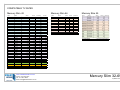
1
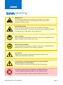
PRODUCT MANUAL Mercury Slim Ceiling Tilt CAUTION Safety Warning Moving Parts: Do not obstruct operation of mechanism with fingers or any object. Injury or damage could result. If adjusting the limits, do so prior to wiring into control systems. Risk of Electrocution: Do not connect any power to the lift until installation is complete. Attach the display panel after the lift has been properly installed and tested. Unit operates on a 240V with a current draw of 1A. Wear a Hardhat: During installation this product or parts of it may move in unexpected ways. Wear a hardhat to ensure safety at all times. Wear Protective Eyewear: During installation this product or parts of it may move in unexpected ways. Wear protective eyewear to ensure safety at all times. Be Prepared: Organise your mounting hardware and have the necessary tools readily accessible before installation. Do not expose to extreme temperatures or corrosive materials. Minimize exposure to the elements. This will void your warranty and reduce the life of the product. This product should only be installed by a qualified technician. It may be illegal to install this product in your region if you are not a licensed technician . Doing so will also void your warranty. Manual Revision: v3.0.20130312 Page 2 CONTENTS Table of Contents Parts List 4 Screw Kit 5 Mercury Slim Diagram 6 Pre Installation Preparation 7 Ceiling Cut-Out Sizes 7 1. Installation into Roof Cavity 8-10 2. Mounting the display 11-12 3. Cable management 13 4. Adjusting the limits 14 6. Wiring Operating the Device 15 Motor Controller Wiring 16 Specifications Warranty and Returns Policy 17 18-19 Thank You Thank you for purchasing this Ultralift product. We are sure you will enjoy this unit for years to come. Before installing, operating or adjusting this product, please read this instruction book carefully and completely. Page 3 PARTS Parts Checklist When you receive this product, please do the following to ensure you have all of the needed components included in the package. Open the carton & inspect for damage Locate the following parts: 1 — Ceiling Tilt (Complete with pre-wired IR kit) 1 — IR hand held remote control 1 — Screw Kit (see next page) Page 4 PARTS Screw Kit: Mercury Slim A M4 Pan Phillips screws (16mm Long) Quantity: 4 For fastening certain Screens to Hanging Rails C B M5 Pan Phillips screws (16mm Long) Quantity: 4 For fastening certain Screens to Hanging Rails D M6 Pan Phillips screws (16mm Long) Quantity: 4 For fastening certain Screens to Hanging Rails F M8 Pan Phillips screws (16mm Long) Quantity: 4 For fastening certain Screens to Hanging Rails H J L M M8 Coach Screw (50mm Long) Quantity: 4 Fastens Mercury to in-ceiling Timber Beams M8 Nuts Quantity: 12 Used with 8mm All Threaded Rod to fasten Mercury to concrete slab inside ceiling 5.3 x 20 x 1.25 Washers Quantity: 8 To fasten Screens to Hanging Rails. For use with: M4x16 Pan Phillips screws (A) - 4 required or M5x16 Pan Phillips screws (B) - 4 required Different Screws (A,B,D,F) are used depending on the screen you have. E G 7.4 x 20 x 1.25 Washers Quantity: 4 For use with M6x16 Pan Phillips screws (D) Cable Ties Quantity: 6 For cable management to keep leads tidy I Motor Key Quantity: 1 Used to adjust motor limits. K M8 Washers Quantity: 12 Used with M8 Nuts (shown left) to fasten Mercury to concrete slab inside ceiling 8mm All Threaded Rod (1000mm Long) - To fasten Mercury Slim to concrete slab above ceiling cavity Quantity: 4 End Caps Quantity: 4 Used to conceal Coach Screws (See Page 10) Page 5 DIAGRAM Mercury Slim Diagram Hanging Rails Ceiling Closure Panel Page 6 PRE-INSTALLATION Important Warning It is critical that the tension of the wires on the Mercury remains unchanged. Changing the tension of the wires will damage the Mercury and void your warranty. To ensure the tension remains unchanged from factory defaults, please note the following: NEVER open or close the Mercury lift manually (i.e. by hand). Doing so may reduce the tension in the wires, causing them to bunch up on the tubular motor and prevent the lift from raising or lowering properly. The wire may snap if this is the case. Safety / Failsafe Catch: Used to ensure that one cable does not give if the other cable snaps. Ceiling Rod : 8mm Threaded Rod to fasten Mercury to concrete slab above ceiling. Wire Spool: The wires should never be crossed over, otherwise the lift will be damaged. Motor Control Box NEVER disconnect wires. Doing so will cause the tension of each wire to become uneven/unbalanced, making the load applied to the lifting mechanism uneven. This can cause the Mercury Lift to malfunction and may cause the wires to snap. Page 7 PRE-INSTALLATION Pre-Installation Preparation Before Installing When choosing your lift, keep in mind variances of the display panel size due to things like speakers on the side, top or bottom. These can increase the size of the lift that you will need. Check that the screen is not larger than the maximum screen size allowed (See specifications at end of this manual). After establishing the correct location for the lift and display panel, cut a hole in the ceiling at the size listed on the following page. Organise a qualified trades person to frame up the roof to accommodate the Ceiling Tilt so that it can be mounted in the correct position. Route AV cables from the source to the roof location where the Lift will be installed. Ensure that a double power point has been installed in the roof (or where suitable) so that the Lift and display panel can receive power. Before mounting the display panel to the Lift, ensure that it will suit the Lift in relation to dimensions, loading capacity and functionality. Read instructions completely before proceeding. Follow instructions carefully. Installation contrary to instructions invalidates warranty. CAUTION: Do not obstruct operation of lift with fingers or any object. Injury or damage could result. Check above the ceiling for obstructions (i.e. water pipes, cable and duct work) before beginning installation. Do not connect any power to the lift until installation is complete Attach the display panel only after the lift has been properly installed and tested. Unit operates on a 240V with a current draw of 1A. If adjusting the limits, do so prior to wiring into control systems. Organise your mounting hardware and have the necessary tools readily accessible before installation. Ceiling cut-out sizes Please refer to the Ceiling Cut-out sizes (CW and CD) in the Specifications table at the end of this manual. Page 8 INSTALLATION Installation into Roof Cavity (1 of 3) This is best done with two to three people due to the weight of the lift. The following instructions apply to both a ceiling joist and a slab / suspended ceiling. CAUTION: The screen should only be fitted to the lift when installation of the Mercury Slim has been completed. Installer must ensure lift is secured in the ceiling. Preparation: 1. Mark out the ceiling cut out as per sizes on page 4, then cut the hole in the ceiling. 2. Frame up the ceiling joists and hanger rails using a qualified trades person (as per figure on next page). 3. Route the Audio Visual cables to the lift position in the ceiling. 4. A double power point is required in the ceiling to power the Mercury Slim and the display panel. NOTE: Access to the power point in the ceiling is advisable. Installation—please see over for diagrams: 1. Cut 8mm threaded rod (Screw Kit Part L) to suit the M8 All Thread distance from the slab / hanger rails to the Lift Length as required with fixing points on the top corners of the Mercury Nuts and washers. Slim. See Fig 1. 2. Fix the pre-cut threaded rod to the slab or ceiling hanger rails as shown in Figure 2 on next page. 3. Fit one M8 nut and washer to each threaded rod. 4. Fit one M8 nut and washer 100mm up from the bottom of the threaded rod. Figure 1. 5. Raise the Mercury Slim unit into the pre-cut hole from the underside. Fit the threaded rod through the top frame of the lift. Fit nuts and washers to suspend the lift as shown in Figure 2 on next page. 6. Adjust nuts until the lower frame sits 1-2mm above the plaster underside. Screw a minimum of four M8 x 50 coach screws through the fixing holes on the inside frame of the Lift, into the pre-built timber support frame. (See Figures 2, 3 and 4). Cover the bolts with the supplied end caps (Screw Kit Part M) as shown in Figure 5. 7. Route the AV cables into the lift as per diagram on page 13 (cable management). 8. Expose the IR eye in a suitable position to achieve line of sight to the remote. 9. Expose double sided tape on loose corflute dust cover and fit to frame. Page 9 INSTALLATION Installation into Roof Cavity (2 of 3) Figure 3 Fasten 4 Coach Screws into Ceiling Joists through holes in the framework. Page 10 INSTALLATION Installation into Roof Cavity (3 of 3) Figure 4 Fasten Coach Screws into Ceiling Joists. Figure 5 Cover coach Screws with white Plastic end caps. Page 11 INSTALLATION Mounting the Flat Panel Display 1. Connect power to the lift and lower lift using the IR hand held remote 2. Disconnect power to the lift 3. Remove the Mount Rails by loosening the two 5mm locking screws. 4. Fit the rails to the back of the screen and bolt using the four Phillips head screws and washers, as per diagram below, noting the orientation from the top of the screen to the top of the rails. Depth Width Rail Offset MOUNTIN G HOLES Height BACK OF SCREEN Page 12 INSTALLATION Mounting the Flat Panel Display (Continued) 5. Lift the display Panel and hook rails onto the lift. 6. Tighten the locking screws to lock the rails into position, ensuring that the screws are tight. 7. Ensure the display panel is mounted centrally Step 5: Lift display panel And hook rails onto lift. Step 6: Tighten locking screws to lock the rails into position. Page 13 INSTALLATION Cable Management 1. Connect cables to the display panel and run down cable management arms as per diagram below. Be sure to allow the extra cable length on the cable management arm bend points. 2. Reconnect power to the lift. CAUTION: Cables must be securely attached to the frame to avoid pinching of the cables. Raise and lower the lift several times using the IR hand held remote, closely watching the cables to make sure they don’t interfere with the lift operation. Please note that the installer is responsible for ensuring the cables do not interfere with the mechanism as the unit raises and lowers. AV and Power Outlet Cables to Screen Page 14 WIRING Adjusting Motor Limits When adjusting the motor limits use the motor key. If adjusting the limits, do so prior to wiring into control systems. 1. Lower the Lift using the IR hand held remote. 2. Adjust the motor down limit if required with caution. 3. Raise by adjusting the desired up motor limit. CAUTION: When setting the motor limits, adjust the Up and Down limits with caution. The Up and Down limits are set in the factory to recommended positions. Minor adjustment may be necessary. In the rare case that the factory settings are slightly out, the down limit may be adjusted with caution. Minor adjustment may be necessary if the weight of your screen or projector has sagged the cable length. Up limit adjustment screw. ADJUST WITH EXTREME CAUTION. Turn clockwise for more lift. Turn anti-clockwise for less lift. Drum Rotation Direction: The hole above the double arrows is to adjust how far the Drum turns in “Direction I”. The hole below is to adjust how far the Drum turns in “Direction II.” Down limit adjustment screw. Turn clockwise for more drop. Turn anti-clockwise for less drop. Page 15 INSTALLATION Operating the Device Remote Control Motor Controller Specifications Input: 220VAC/50Hz ±10% Output: 220VAC/2.5Amp Maximum motor running time 5 minutes Both RF and IR receiver; Dry contact closures. External IR Lead; Built in IR Eye. 12 Volt trigger input for projectors Programmable Motor Controller Box (Side View) Hex Codes SW4 0x0B 0x43 0x23 Please Note: DO NOT OPEN BOX WITH POWER ON! Please Refer to instructions on inside of Motor Controller Box lid for further instructions. IR1 QUICK PROGRAMMING: TRANS Aim the Remote control unit towards the receiver IR eye (IR1) or to the external IR eye while programming. Please refer to above diagram for the location of the Infrared eye (IR1), 2 pushJPbutton switch (SW4), & LED light (LED1). PAIRING REMOTE CONTROL RELAYTO RECEIVER: Press SW4 (LED1 blinks) then press the UP button of the remote control unit. UNPAIRING REMOTE CONTROL FROM RECEIVER: Press SW4 (LED1 blinks) then press the DOWN C ar li JP 1 C ar li C N T1 unit. button of the remote control UNPAIRING ALL REMOTE CONTROLS FROM RECEIVER: JP 2 Press and hold SW4 for about 4 seconds until N then E release E NtheL R LED1 blinks at fasterLrate, AC again. IN MOTOR Button. Then press SW4 REVERSING THE UP-DOWN BUTTON DIRECTION: Press SW4 (LED1 blinks) then press the STOP button of the remote control unit. RELAY Depending on the device the motor control box is connected to, the codes for UP and DOWN may be reversed. LED1 CNT2 UP DOWN STOP 4 2 GND NC 1 NC +12V 3 2 4 6 IR ST O P GND + 5 V UP 1 3 D O WN 5 Page 16 INSTALLATION Motor Controller Wiring The Motor Control box may be connected to Automation systems using IR, 12V trigger, or Contact Relay. Power LED under IR1 (LED1) IR Eye (IR1) Receives Infrared signals from remote control through IR window. Illuminates when Motor Controller is connected to AC Power. White in appearance. Located on PCB surface. 12V Trigger (JP2) Program Button (SW4) Used to pair/link remote controls with the Motor Controller. AC Main Power (CNT1) A: NC B: GND C: +12V D: NC External IR (IR2) Used to connect a lead to an external IR Eye. A: +5V B: IR SIGNAL F: GND L: ACTIVE N: NEUTRAL E: EARTH Motor Cable Terminal (CNT2) Power Cable Motor Cable Dry Contact (DRY1) Used to connect Motor Controller to Dry Contact. C: UP D: STOP E: DOWN F: COMMON DO NOT OPEN BOX WITH POWER ON! Please Refer to instructions on inside of Motor Controller Box lid for further installation instructions. E: EARTH N: NEUTRAL L: UP OR DOWN R: UP OR DOWN Page 17 NOTE: PRODUCT DIMENSIONS ARE SUBJECT TO CHANGE Cutout Width (CW) PLEASE CALL US TO CONFIRM DIMENSIONS BEFORE PURCHASING, BUILDING FURNITURE, CUTTING INTO WALLS, CEILINGS OR FURNITURE OR PREPARING FOR INSTALLATION. IMPORTANT: As we develop new products, please confirm cutout sizes prior to cutting into the ceiling. Cutout Size (mm) Max screen size (mm) Description SD SW SH Mercury Slim 32 Compact screen ceiling tilt 32" 85 1000 710 135 Call us for sizes 30 800 530 Mercury Slim 40 Compact screen ceiling tilt 40" 87 1195 860 148 Call us for sizes 30 1016 660 Mercury Slim 42 Compact screen ceiling tilt 42" 121 1188 874 192 1200 885 58 1018 643 Mercury Slim 46 Compact screen ceiling tilt 46" 100 1251 874 194 1260 883 57 1073 663 Mercury Slim 55 Compact screen ceiling tilt 55" 85 1520 1030 207 1530 1040 30 1336 815 Mercury Slim 60 Compact screen ceiling tilt 60" 82 1531 999 Call us for sizes 30 1357 779 Mercury Slim 65 Compact screen ceiling tilt 65" H Cutout Depth (CD) CEILING CUTOUT Dimensions (mm) Model W D O 233 CW CD Dimensions available upon application. SEE OVERLEAF FOR A LIST OF SUPPORTED TV MODELS Overhang (O) Depth (D) Height (H) Width (W) x 20 Ma Tilt This work is copyright. Apart from any use permitted under the Copyright Act 1968, no part may be reproduced by any process, nor may any other exclusive right be exercised, without the permission of Ultralift Australia www.ultraliftaustralia.com.au Phone: +613 9459 0873 Fax: +613 9457 6686 Email: [email protected] Mercury Slim 32-65 Updated: 5/3/13 COMPATIBLE TV SIZES Mercury Slim 42 Mercury Slim 46 MAKE MODEL WIDTH HEIGHT THICKNESS WEIGHT PANASONIC PANASONIC PANASONIC PANASONIC PANASONIC PANASONIC PANASONIC PANASONIC PANASONIC PANASONIC PANASONIC PANASONIC TH-L42E30A 1002 611 75 15 TH-L42E3A LG LG LG LG LG LG LG LG LG LG LG LG LG LG LG 1002 611 75 15 TH-L42DT50Z 958 569 27 11 TH-L42ET50Z 989 643 36 15.5 TC-L42ET5 997 604 40 14 TC-P422ST30 1021 640 71 20 TC-P42UT50 1009 616 84 17.5 TC-L42E50 997 604 40 14 TC- L42E5 997 604 40 14 TC-L42D30 988 600 33 16 TC-P42S30 1021 640 71 19 TC-P42ST30 1021 640 71 20 42LW5700 999 623 30.9 13.4 42LV 3730 988 615 30.4 13.3 42LV5500 1012 617 29.9 13.2 42LW6500 1009 622 29.9 13.4 42LM7600 953 566 33.4 12.8 42LE4500 1018 627 29.8 14.2 42CS460 1017 629 76.5 13.5 42LS5700 979 594 35.5 12.7 42LM6200 979 594 35.5 13.1 42LM6700 953 566 33.4 12.6 42LM6410 964 577.7 35.7 12.1 42PT250 987.6 608.9 52.5 42LK450 1019 631 76.5 42PA4500 983.6 601.3 58 42LS4600 979 594 35.5 12.7 SONY KDL-42EX440983 983 603 75 13.2 HI-SENSE HL42K316PZL3D 986 600 58 15.5 PHILIPS 42PFL5907 589 58 58.9 OTHER MODELS 997.2 WIDTH Mercury Slim 55 MAKE MODEL SAMSUNG SAMSUNG SAMSUNG SAMSUNG SAMSUNG SAMSUNG LG SHARP SHARP SHARP UA46ES7500M 1046.8 HEIGHT 620.2 THICKNESS 29.7 UA46ES6200M 1062.8 631.1 46.9 UA46ES5500M 1062.8 631.1 46.9 UA46ES6600M 1063.2 636.4 43.7 UA46ES6800 1070.2 635.6 46.9 UA46ES6700M 1070.2 635.6 46.9 47LM6700 1063 627 33.4 LC46LE835X 1072 663 41 LC46LE830X 1072 663 41 LC46LE840X 1073 652 57 OTHER MODELS MAKE MODEL WIDTH HEIGHT THICKNESS with Max Size of 1073x663x57mm OTHER MODELS with Max Size of 1281x774x60mm With Max Screen Size of 1018W x 643H x 58D www.ultraliftaustralia.com.au Phone: +613 9459 0873 Fax: +613 9457 6686 Email: [email protected] Mercury Slim 32-65 Updated: 5/3/13 RETURNS POLICY Page 1 of 2 Warranty and Returns Policy At Ultralift Australia Pty Ltd, we take pride in the fact that our products are of the highest quality. Because of this, we offer the following programs to ensure your satisfaction. ULTRALIFT 2 YEAR WARRANTY 1. The product is warranted for 24 months from the date of invoice. Subject to the conditions of this warranty, Ultralift Australia or an authorised installer will perform necessary service on the product without charge for parts or labour if, in the opinion of Ultralift Australia, the product is found to be faulty within the warranty period. 2. This warranty only applies to Ultralift Australia products when purchased from Ultralift Australia or from an authorised dealer. 3. This warranty only applies if the product has been installed and used in accordance with the manufacturer’s recommendations (as noted in the instruction manual) under normal use and reasonable care (in the opinion of Ultralift Australia). The warranty covers normal domestic, commercial or educational use only. It does not cover damage, malfunction, neglect, build-up of dirt or dust, abuse, maladjustment of customer controls, mains supply problems, thunderstorm activity, infestation by insects or vermin, tampering or repair by unauthorised persons (including unauthorized alterations), exposure to abnormally corrosive conditions or any foreign object or matter having entered the product. 4. If warranty service is required you should: Contact your installer for advice on how to rectify the issue. If this does not solve the problem please call Ultralift Australia on 61 3 9459 0873 for advice. If the device requires service, return the product to Ultralift Australia for repair. Please Note: Freight and insurance to and / or from the location of the device must be arranged by you. Please ensure that items returned are packed in an appropriate manner. 5. The warranties hereby conferred do not extend to, and exclude, any costs associated with the installation, de-installation or re-installation of a product. This includes costs related to the mounting, de-mounting or re-mounting of any screen, (and any other ancillary devices), delivery, handling, freighting, transportation or insurance of the product or any part thereof or replacement to such installation, deinstallation, re-installation or transit. Ultralift Australia Pty Ltd Email: [email protected] Web: www.ultraliftaustralia.com.au Phone: 61 3 9459 0873 Fax: 61 3 9457 6686 10 Vernon Ave, Heidelberg Heights VIC 3081 Australia RETURNS POLICY Page 2 of 2 OUR HASSLE FREE RETURN PROGRAM Our thirty day return program means you may return your purchase, excluding special orders and/ or non stock products, to us should you be dissatisfied with your purchase within thirty days of receipt of the product. You must return the item(s) to us by 2nd day freight, insured for full value, with original packaging, documentation, all manuals and accessories. Freight charges, for delivery and return and related insurance charges, will not be refunded or credited. There will also be a restocking fee of 15% of the purchase price. CONDITIONS OF RETURNED ITEMS Do not write on the box. If the box is written on, the returned product will be refused. Be in the original shipping carton with all original packing material. Include all accessories in their original wrapping/packing material. The actual replacement cost for missing items will be deducted from your refund/credit. Include all manuals, warranty information and instructions. The actual replacement cost for missing items will be deducted from your refund/credit. DEFECTIVE OR D.O.A. PROGRAM In the case of defective or D.O.A. product(s), no charges will apply. Our Customer Service team must be notified within 30 days of your invoice date if there are any problems with any item(s) upon receipt. Defective or D.O.A. merchandise will be repaired and returned or exchanged for the same make or model. FOR ITEMS DAMAGED DURING TRANSPORT Ultralift Australia Pty Ltd endeavours to use reputable carriers, but occasionally shipping damage does occur. Resolving the problem of transit damage or loss depends on the cooperation of all parties. In the event of damage or loss it is imperative that you follow these guidelines: 1. Inspect all shipments upon arrival. If damage or loss is apparent upon delivery, do not accept the goods and do not sign for damaged or missing cartons. If you do accept the goods, keep all packing materials and boxes with the damaged product. 2. Immediately advise Ultralift Australia of all damages or problems with the delivery of goods. REFUNDS Established Account: A full refund will not be issued if the purchaser’s account has an open balance. A credit memo will be issued, and credit will be applied first to the invoice on which the products were purchased, then to any other open invoices on the account, beginning with the oldest invoice. Credit Card / EFT: All refunds for purchases made by Credit Card/EFT will be issued as a credit to that same account within a reasonable period of time after inspection of returned products. Cheque: All refunds for purchases paid by cheque, whether prepaid, C.O.D., or account, will be paid by cheque within a reasonable amount of time, after inspection of returned products. Ultralift Australia Pty Ltd Email: [email protected] Web: www.ultraliftaustralia.com.au Phone: 61 3 9459 0873 Fax: 61 3 9457 6686 10 Vernon Ave, Heidelberg Heights VIC 3081 Australia THANKYOU FOR CHOOSING Ultralift Australia Pty Ltd 10 Vernon Ave, Heidelberg Heights VIC 3081 Australia Email: [email protected] Web: www.ultraliftaustralia.com.au Phone: 61 3 9459 0873 Fax: 61 3 9457 6686