1
I~
----
=-,---~-,-"'~-,~""=
I
MC 800 LCD Fishfinder
-
'p"
if
)'
~\.
--~---
,..
f
i
~----
1-
Table of Contents
Welcome!
]
",
1
""""""""""""""
Unpacking
Controls and Functions
Controls and Functions - Cont'd
Controls and Functions - Cont'd
MC800 Indicator Unit - Controls. . . . .
Features
MC 800 Indicator Unit - Display. . . . .
Installation - Indicator Unit. . . . . . . .
Installation - Indicator Unit - 2 . . . . . .
Installation - Indicator Unit - 3 . . . . . .
Installation-ConnectingPower
Installation-Transducer-General
Installation-Transom
Mount
Installation - Transom Mount. . . . . . .
Installation - Thru-Hull Mount.
... . .
Installation - Wet Box Mount.
. ... ..
Installation-Direct
Mount
Installation-Cabling
Operation
Basic Operation
Turning the Power on
Setting the Auto mode
Setting the Depth range
Setting the Zoom range
Setting the Sweep Speed
Operation-Continued
Setting the Gain
Silencing the Audio Alarms
Setting the Shallow Alarm
To silence the Shallow Alarm
Operation-Continued
Setting the Deep Alarm
To silence the Deep Alarm
Setting the Fish Alarm
To silence the Fish Alarm
Using the Flash Mode
Using the Display Freeze
Using the Backlight
Operation-Continued
Using the Simulator Mode
Digital Display Mode
"'-""--"""'--'-""""-""""""""""""""---"""-"""""""""""""""-""""""""""""""
. . . ..
. . . . . . ..
.
.
.
.
.
.
.
.
..
..
".
..
.
.
.
.
.
.
.
.
..
..
..
..
. . . . . . ..
. . . . . . ..
. . . . . . ..
2
3
4
5
6
7
8
9
10
11
12
13
14
15
16
17
18
19
20
21
22
---==
(~
Table of Contents
I
I
AnchorWatch
Contour Navigation
23
24
Interpreting Screen Pictures - 1
,
25
Interpreting Screen Pictures - 2 . . . . . . . . . . . . .. 26
Interpreting Screen Pictures - 3 . . . . . . . . . . . . .. 27
Interpreting Screen Pictures - 4 . . . . . . . . . . . . ..
iI
Interpreting
i
\
- 5 . . . . . . . . . . . . ..
Screen Pictures
Interpreting Screen Pictures
Interpreting Screen Pictures
!
I
Interpreting
I
i
I
Screen Pictures
-6
-7
. . . . . . . . . . . . ..
. . . . . . . . . . . . ..
28
29
30
31
-8 . . . . . . . . . . . . ., 32
Specifications
Troubleshooting
Warranty
Warranty-Cont'd
33
34
35
36
\
I
i
1
I
~,
b_-b
ob
b-
--
_b
_u-
- --_c"~1--"
---
_. ". -.,.-
=",,'," "~'-"",._-,,"=
---~
Welcome!
to the world of high tech marine electronics. Your Uniden MC 800
represents the finest in LCD Fishfinding technology. It's Super Twist
Nematic Liquid Crystal Display gives you the clearest, easiest to see
display in LCD Fishfinders today. And, the display won't "wash out"
in bright sunlight like other fishfinders.
Unpacking
When unpacking your MC 800, the following items should be found
in the box. If an item is missing, please contact yqur Uniden dealer
immediately.
.
.
.
.
.
.
.
.
MC 800 Indicator Unit
200 KHz Transducer Kit, (Transom or optional
Thru-Hull Mount) with a water temperature senser
Power Cable with inline fuse
Gimbal Mounting Bracket
Swivel Mount Kit (optional)
Gimbal Mount Clamping Knobs x2
Clamping Knob Rubber VVashersx2
Instruction Manual
-1-
--1:
I.
=..
-==:
"'-'-'~
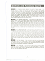
Controls and Functions
0
...
1. Power On/Off and Simulation
On/Off Key - This key is
used to turn the unit on or off, and to begin the simulation mode.
Press once to turn the power on, press again to turn the power off.
Press and hold for more than 2 seconds when turning the power on
to enter the simulation mode.
~
2. Backlight On/Off Key - This key is used to turn the
display backlighting on and off. Press once to turn on, and press
again to turn off.
-
~
3. Alarm Clear, Alarm Buzzer and Zoom On/Off Key Use this key to shut off the audible alarm when it sounds for either
the shallow, deep, or fish alarms. To clear an alarm or zoom, first
press the associated key (either shallow, deep fish or zoom) and then
press the reset button.
4. Up or increase Key - This key is used in conjunction
with the depth range, zoom range, shallow alarm, deep alarm, gain
level, and display sweep speed controls. Pressing this button will increase or raise the appropriate item.
---
5. Downor DecreaseKey- This key operates in a similar
fashion to the up or increase key, except that this one decreases or
lowers the appropriate item.
IimimII 6. Depth Range Selection - This key is used with the A
and A keys to set the range to display. To set the range, first press
this key, t-hen use the A or V key until the desired range is indicated
on the display.
I
IE!mII
7. Automatic Operation - Pressing the Auto key tells your
MC800 to automatically select the optimum range, gain, and sweep
I
speeds for clearest viewing. The word 11AUTO" is displayed at the
I
I
!
I!
bottom of the screen when in this operating mode.
;
Ii
II!mDII 8. Gain level Control - This control is used to set the gain
of the receive section for maximum clarity. It is usually set to the
highest point possible before interference is shown on the screen. To
use this function, first press the Gain key, and then use the A and V
keys to set the gain to the desired level. The gain is shown on the
Gain bar graph at the top of the LCD screen. The gain is adjustable in
8 steps.
I
!
I
I
I
-2-
I
f
1-
T
"'---'-"'--'-
..,
..
..-- .
"-'-.'
,:",."-,,-_c,,,c=-='"F
'- '---.
-~-
;;:
Controls and Functions-Cont'd
~
9. Display Sweep Speed Key with Freeze mode - The
Sweep button is used to control the speed at which the display
moves across the screen to compensate for boat speed. You can also
freeze the display for closer examination of interesting underwater
features. To set the display sweep speed, first press the Sweep key
(which will freeze the display), and then use the 1\ and V keys to
adjust the sweep to the desired speed. The sweep speed is displayed
on the Sweep Bar Graph at the bottom of the display. There are
eight possible settings for the Sweep speed.
~
10. Shallow Alarm Set - This control is used with the 1\
and V keys to set the depth above which the audible alarm will
sound; i. e. if the shallow alarm depth is set to 20 feet, and you take
your boat into water 19 feet deep, the alarm will sound. To set the
shallow alarm, first press the Aim S key, then use the 1\ and V keys
to set the alarm to the desired depth. The depth that the alarm is set
to is displayed on the bar graph at the right side of the display. When
the alarm is set, a black bar will extend down from the top of the
display.
EmI!J
11. Deep Alarm Set - This control is used with the 1\ and
V keys to set the depth below which the audible alarm will sound;
i. e. if the deep alarm is set to 20 feet, and you take your boat into
water 21 feet deep, the alarm will sound. To set the deep alarm, first
press the Aim D key, and then use the Up and Down keys to set the
alarm to the desired depth. The depth that the alarm is set to is displayed on the bar graph at the right side of the display. When the
alarm is set, a black bar will extend up from the bottom of the display.
E::I
12. FishAlarm- This
control
is used to turn the audible
Fish Alarm on or off. Press once to turn on, and press again to turn
off. When the Fish Alarm is turned on, the audible alarm will sound
anytime an echo above the bottom is detected.
~
13. Flash Key - This control is used to turn the echo flash
mode on or off. Press once to turn on, and press again to turn off.
When the flash mode is on, all echoes above the bottom will flash on
and off, to call attention to them.
-3-
=:1
'-"'-""""'-"'-"'--""-'-'-"""'--""""-"~"""""'-"'"
..."
.m..""""""""
""""""""""
",-"""","""'-'"
""""""":""'-'==l""""'--'--'
""'-'--""
-~
-===
---',--.,.c=
.....
-
Controls 'and Functions-Cont's
~
14. Zoom - This control
is used with the A, V, and Reset
keys to set the Zoom range. To initiate this mode, press the Zoom
key once, and the vertical zoom cursor will appear on the right side
of the screen. Set the desired Zoom range by moving the cursor with
the A and v, then press the Zoom key again. The Zoom range scales
appear with a digital numeric display, Zoom mode starts, and an
expanded (zoomed) chart appears over the whole of the screen. The
Zoom range is normally set to 15 feet, but can be changed in 1 foot
increments. You can also change the Zoom setting while in the Zoom
mode by pressing the Zoom key, and then either the A or V keys to
change the Zoom position.
~
15. Digital Display Mode - This control is used to turn the
Digital Display Mode on or off. When you first turn the unit on, the
display will show the normal chart display mode. Press the DDM
button once to give you a large Digital Depth and Water Temperature
display. Press the DDM or AUTO buttons to return to normal chart
display mode. While in DDM, all functions except AUTO and LIGHT
are disabled.
16. Key Press Timing - In case you did not press a subkey within 5 seconds after you pressed a function key, the keying is
cancelled with a short beep tone.
-
!
i
i
J
I
I
I
I
!
j
-4-
-r
-'--"
-- "n._-'-
.. ---' ---,,_"':c,:,c~l'
'
=t,
~~
..-'""
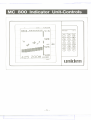
MC 800 Indicator Unit-Controls
GAIN
F
-
ALMIZOOM
.. , '"
I, ...
=':
M:
[! !J.fJ _..::.::.:~-~:.=.:~'::'-~
~
: ..': 1'
aa!
..
, ,a
...a
a" ..a,
a..
l!il!!1
..,
...
I::
aa
1
LC 0
Auto-
Zoom
'-'"
mm
E! .. a"
=!
!: E. ,.! =.:
r-El
Range
@@@
ii
I
,
MC800
G)@@
AimS Aim 0 -~
11
m
--
~
/"..
Gain
@(D@
Sweep
Flash
DDM
@@@
Reset
0
CD
pmr
i! 1.1::11:1
,'I a"': !:::'
1"1' I:::a a,..i
a?
\,' , lili!iH
: ri
'a..' r'!
..aal
-5WP-
-5-
uniden
p
~-
:=--r
~
~
.--.
(~
\
Features
The Uniden MC800 has a large number of features that make it easy
to use. These are:
. Automatic Operation
. Shallowand Deepalarmswith on-screengraphs
.
Audible Fish Alarm
.
Variable Sweep Speeds
.
.
.
Adjustable Gain
.
Display Freeze
.
.
.
.
.
Display Backlighting
Digital Depth Display
Digital Range Display
Simulator Mode
Zoom Function
Flash Mode
Surface Water Temperature Display
Refer to the section on operation for details on how to use these
featu res.
-6-
---{:
-
-
-
-
-
-
-
-
-
~
~~
I
_.-.-..
c..:-==
,
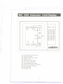
MC 800 Indicator Unit-Display
GAIN
F
r':':
:'1
:': :': ::
Mf:':
01
ALMIZOOM
mm ":mmmmm
,
't
,
1
",..,
M 1 :' !
MC800
02611
11; r'
03---!1 010
:' ..! I';
Auto RangeZoom
0@@
AimS Aim0 -.
@@@
"! 1:,_,I
--
04---i!
06
09
08
t
'-/
/'..
Gain
00@
:::::: I~
5!
..:1
!
5: ' ;' . :,;
Sweep Flash DDM
..
.. 1,....,
05
L CD
@@@
-I
CD
0
PCDr
55
£i1.1::1[I
~
! .., , ...';..'
,'-I:..,
-:111 ,-, ,"1'
:..:,,"
,'I:!,'..,'...'
: :..., '..,1 :...,
, mUI!!
1I
07
uniden
-5WP-
D1, Surface Water Temperature
D2, Gain Bar Graph
D3, Shallow Alarm Bar Graph
D4. Zoom Cursor
D5, Deep Alarm Bar Graph
D6, Fish Alarm Indicator
D7, Sweep Speed Bar Graph
08, Zoom On or Auto On Indicator
D9, Cu rrent Depth Readout
D10. Degital Scale
D11.Surface Line
-7-
-
-
-
-
--
~.
t
m --
--
-
- ---
--
---
.--------..
~!
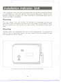
Installation-Indicator
0
Unit
0
0
I
0
The Indicator Unit may be mounted with the gimbal mounting bracket (included) or with the swivelbase mount (optional). Select a convenient location suitable for easy viewing in a sheltered area out of
direct sunlight if possible.
Warning
Do not mount the unit within 18 inches of a compass, as the unit
generates high frequency pulses which may affect it's accuracy. Also,
do not install any wiring for the unit within 18 inches of your compass.
Warning
Uniden does not represent this unit to be waterproof. To reduce the
risk of fire or electrical shock, do not mount this unit where it may
be exposed to rain or spray.
11
PWR
01o)
D
TO
e
<D
To mount the unit with the gimbal mounting bracket
-8-
-
--===
=-
!
i
Ij
I
,
it
I
I
:1
-t~c----------------------_.-
",,---
Installation-Indicator
Unit-2
MOUNT AT LEAST
19" OR 50cm FROM COMPASS
-°""-""'00'
MC800
[i[i,n,-"c::.:':::;.:~~:'::ii"iiS
ii
LCD
00@
II
LJ2[J
I
@'(fuD
@'
00@
'G5'@@
!I"'"
CD(D'GS'
';, "j!" "~:r ,;
n
I
I
,,-1-
L "'.
li
"LI:II]
1
'
'j,- ,... ~ - _
':T'::::'
,:J",IU'1
11111111
uniden
To mount the unit with the gimbal base mount
Ceiling Mount
-9~_._.
--.----.
---=
~_.._........--
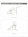
Installation-Indicator Unit-3
Side Wall Mount
--
,/
On-Dash Mount
-10 -
==f
-
--
~
,
0
InstaIlation- Connecti ngPower
The MC 800 will work with any ship's 12 volt nominal DC voltage.
(see specifications
for more details) Connect the power cable furnished to a DC source capable of supplying at least 1.0 amperes of
current. The power leads should normally be routed to the ship's DC
power distribution
panel (on larger boats) or directly to the battery
main circuit breaker (on smaller boats).
Be sure to observe the proper polarity when connecting the power.
The red lead wire of the power cable should be connected to the
positive terminal, and the black lead should be connected to the
negative terminal.
Warning
The indicator unit is protected by an inline 1.0 ampere fuse. To
reduce the risk of fire or electric shock, replace this fuse only with
one of the proper specification.
(D
(D
~
D
(D
(D
- 11 -
f
- --- -
- - --" - - ~=
=-- - -- -- -,--I
~-
--
--=
,'..=.,-"".._,~..=
Installation-Transducer-General,
Transducer
The MC 800 is designed to work with either a transom mount type
200 KHZ transducer, or a thru-hull mount 200 KHz transducer.
The transducer element is that portion of the system that converts
the electrical pulse from the sounder into a sound wave which is
transmitted downward to the bottom and returned as an echo. This
echo is picked up by the transducer, converted back into an electrical
signal, and sent to the sounder, which then measures the time the
echo took to return and converts this information for display on the
unit.
The transducer is the heart of the system. It is a delicate instrument
and should be handled accordingly. The thru-hull transducer element
is housed in a lexan casting with an epoxy surface. The epoxy surface
is the "window" through which the ultrasonic pulses travel, and
therefore should be as smooth as possible.
Note
Use extreme caution when handling, installing and using the transducer to prevent damage to the transducer [ace.
Also, when handling the transducer, avoid lifting by, or pulling on
the transducer cables. This can cause damage to the cable causing
failure at an inopportune time.
Since the mounting location of the transducer will vary with the type
of vessel and it's particular type of hull construction, the following
mounting rules generally apply.
Mount the transducer
.
Where it will be continually immersed in water when the vessel
under way.
. Where turbulent water will not passover the transducer face.
. As far from the engine and propeller aspractical.
Where it will be protected from striking submerged objects.
.
Hull Type
Mounting Method
Thru-Hull
Wet Box
.J
Double Hull
Foam Cored
BalsaCored
Wood
Solid Fiberglass
Steel
Aluminum
Transom
Direct Bonding
.J
.J
.J
.J
.J
.J
.J
.J
.J
.J
.J
.J
.J
.J
.J
.J
.J
.J
.J
-12 -
==r
._~
--- ~=
"'-"
.
==~~~...'
"'
'-~':=-~l
--.--
<:
-=
~
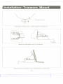
Installation- Transom
Mount
Installation of the transom mounted type of transducer is illustrated
below. Ideally, the transducer should be mounted so that the face of
the transducer is perpendicular with the sea bottom. On boats with
one propeller, the transducer should be mounted at least 15 inches
(400mm) either side of the centerline to minimize the effects of
turbulence. Depending on the direction of rotation of your propeller,
the transducer should be mounted either of the left or to the right of
the propeller. (see drawing below). When installed, the tilt angle of
the transducer should be less than 10° for maximum efficiency.
Once you have determined the best possible mounting location, proceed as follows:
.
Check to make sure that the transducer and bracket are correctly assembled (see below)
.
If necessary, adjust the bracket angle to conform to the angle
(rake) of the transom.
. Verify that the face of the transducer is within 10° of horizontal.
. Mark and install the transducer/bracket
som with screws.
assembly to the tran-
Warning
Use caution when installing the screws for the mounting bracket so
as not to breach the integrity of the hull. It may be necessary to install backing plates, etc. to be able to mount the transducer.
TRANSDUCER
Transducer Mounting - CCW Propeller Rotation
- 13'
I
---.
.. -
--
""""'='r
---
E
-=-----/
Installation.-Transom Mount
TRANSDUCER
Transducer Mounting - CW Propeller Rotation
~
5° - 10°
ANGLE
Mounting Bracket and Transducer
~='
Mounting the Bracket and Transducer to the Hull
-14
--_:
~--=---=
-
--
-- - . ~\~-~
1
-===
-"'--~---",,---,,=
Installation-Thru-Hull Mount
Drill a hole in the bottom of the boat large enough to accomodate
the stem of the transducer. Use fairing blocks to "sandwich"
the
transducer and to waterproof the area of installation. By shaping the
fairing block located beneath the hull, you can reduce the amount of
drag on your boa't. This is the best mounting for obtaining maximum
performance from your system, however, there are also disadvantages
to this type of mount, such as:
.
.
Damage can be caused to the transducer and/or hull when loading or unloading your boat from a trailer.
Damageor sinking can occur if the transducer strikes a submerged object while boating.
. Barnacles and other marine life will attach to and grow on the
transducer impairing performance.
.
This type of mount will cause noticeable drag on high performance hulls.
NUT
FAIRING
CANVAS WASHER
~
"
BLOCK
BOAT HULL
FAIRING
TRANSDUCER
Thru Hull Mount
-15
-
BLOCK
---
"
-0'
=--
Installation-Wet Box Mount
..
The second best type of mounting (where practical) is the "Wet Box"
method. With this type of mount, it is an absolute requirement that
the hull is solid, and not a double hull or cored hull design. Use a
piece of PVC pipe or similar material to create a small chamber.
Epoxy the pipe in place against the hull, being sure that the epoxy is
applied all around the pipe so that it will hold liquid. Make a lid to
fit the top of the chamber and mount the transducer to the lid. Fill
the chamber with mineral oil which won't evaporate or causecorrosion as water would. In operation, the signal is transmitted through
the mineral oil and through the hull. (The viscosity of the mineral oil
will not affect the accuracy of the display.) The primary advantages
of this type of mount is that there is no hole through the hull to
compromise it's integrity, and the transducer is protected from the
growth of marine life.
If using this type of mount on a tri-hull or cathedral hull, make sure
that you don't mount the transducer over an air slot.
On planing hulls, make sure that the transducer is mounted over an
area that is always submerged.
A transom mount transducer may also be used.
If you use this type of mounting with your MC 800, you will have to
add an external temperature sensor to obtain water temperatures.
INLET
TRANSDUCER
\
I
1
I
WATER OR
MINERAL 01L
I
I
EPOXY COMPOUN D
I
SOLI D FI BERGLASS, STEEL OR ALUMINUM
HULL
,
Wet Box Mount
-16
t
-
---"- .
.-no
'
' "'
'~1'---'--'-'
-=-=--
1""~c,,~=~,
~
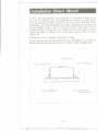
Installation-Direct
-
Mount
In this mounting method, the transducer is mounted directly to the
hull. At the location you have selected for mounting, apply epoxy
or air-free silicone rubber cement to the hull and to the face of the
transducer. Roll the transducer into place, making sure that there are
no air bubbles. Allow to set for at least 12 hours. The signal is transmitted directly through the hull. Please note that this type of mount
cannot be used on double hull, foam cored, balsa cored, or similar
type hulls.
A transom mount transducer may also be used.
If you use this type of mounting with your MC800, you will have to
add an external temperature sensor to obtain water temperatures.
..
TRANSDUCER
EPOXY COMPOUND
EPOXY COMPOUND
..
SOLI D FIBERGLASS
OR METAL HULL
NO AIR BUBBLES
- 17-
t
,---,-
--- -----,
,,
-. ---,
,---"". .""--,,--.---
-'--'--..,--
"-""
-- CCj_:":""_-,--,------
--
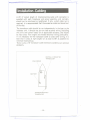
Insta lIati on - Ca bli n9
A 24' (7 meter) length of interconnecting cable with connector is
supplied with each transducer and sensor assembly, and normally
should not be shortened or lengthened. If only a short cable run is
required, it is recommended that the excess be coiled and stored out
of the way.
The transducer cable should be run independently in the boat to the
indicator unit. It should not be run close to other wiring (including
the unit's own power leads) for an appreciable distance, and should
be kept away from engine and related electrical wiring particularly.
If it is necessary for the transducer cable to cross other wiring, it is
best that it cross at right angles (or as close to 90° as possible) to
minimize noise pickup.
There is also a 10' transducer cable extension available as an optional
accessory.
CENTRALL Y-MOUNTED
TRANSDUCER
BATTERY
~
TRANSOM MOUNTED
TRANSDUCER
-18
1:
-
1
,
<:
'
-=
"""
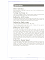
Operation
Basic Operation
Basic operation of MC800 is easy to learn. Use the following examples to guide you.
Turning
the Power on
The unit is initiated at the 0 - 120 feet depth range with the 5th gain
level and 6th sweep speed under the manual operation.
Setting the AUTO mode
To set this operating mode, simply press the AUTO key. To return to
manual mode, press the AUTO key again. While in AUTO mode, the
word 11AUTO" is displayed at the bottom of the screen.
Setting the Depth range
To set the operating range to the 0' - 60' range:
Press the Range button. Use the A. and/or V keys until you see displayed in the right side of the screen.
Setti ng the Zoom range
To initiate this mode, press the Zoom key once, and the vertical
zoom cursor will appear on the right side of the scr~en. Set the desired Zoom range by moving the cursor with the A.and V, then press
the Zoom key again. The Zoom range scales appear with a digital
numeric display, Zoom mode starts, and an expanded (zoomed)
chart appears over the whole of the screen. The Zoom range is normally set to 15 feet, but can be changed in 1 foot increments. You
can also change the Zoom setting while in the Zoom mode by pressing the Zoom key, and then either the A. or V keys to change the
Zoom position.
Setting the Sweep Speed
To set the display sweep speed, first press the Sweep key (which will
freeze the display), and then use the A. and V keys to adjust the
sweep to the desired speed. The sweep speed is displayed on the
Sweep Bar Graph at the bottom of the display. There are eight possible settings for the Sweep speed.
-19 --.---.-.-
===r
~
.=:::::::
---
Operation-Conti
---------
'"
n ued
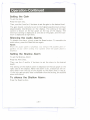
Setting the Gain
To set the Gain:
Press the Gain key.
Then, use the A and/or V buttons to set the gain to the desired level.
The gain should normally be set to the highest possible level without
objectionable interference on the display. The setting of the gain
control is shown on the bar graph on the top of the display. The
minimum setting is displayed as one dot on the graph, and the maximum is displayed as eight dots.
Silencing the Audio Alarms
To disable the alarm, simply press the Reset button. To reenable the
audio alarm, press the Reset button again.
Note:
When the audio alarm is disabled, you will get NO audible alert regardless of any other setting. Use caution when the audio alarm is
disabled.
Setting the Shallow Alarm
To set the Shallow Alarm:
Press the AIm S key.
Then, use the A and/or V buttons to set the alarm to the desired
depth.
The setting of the shallow alarm is displayed on the bar graph on the
right side of the display. When the alarm is set, a black bar will extend down from the top of the display to the depth that it is set at.
If the unit gets an echo that is shallower than the setting, the audible
alarm will sound.
To silence the Shallow Alarm:
Press the Reset button.
-20 -
, "':'
t
~:J
..-..---..
I
,
<:
.
-=
"-=
---
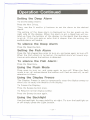
0 perati on -Conti n ued
Setting the Deep Alarm
To set the Deep Alarm:
Press the Aim D key.
Then, use the /\ and/or V buttons to set the alarm to the desired
depth.
The setting of the deep alarm is displayed on the bar graph on the
right side of the display. When the alarm is set, a black bar will extend up from the bottom of the display to the depth that the alarm
is set at. If the unit gets an echo that is deeper than the setting, the
audible alarm will sound.
To silence the Deep Alarm
Press the Reset button.
Setting the Fish Alarm
Press the fish shaped key once to turn on, and press again to turn off.
When the Fish Alarm is turned on, the audible alarm will sound anytime an echo above the bottom is detected.
To silence the Fish Alarm:
Press the Reset key.
Using the Flash Mode
Press once to turn on, and press again to turn off. \!\'henthe flash
mode is on, all echoes above the bottom will flash on and off, to call
attention to them.
Using the Display Freeze
The Display Freeze is used to temporarily stop the display sweep to
allow you to study the details of the display.
To Freeze the Display:
Press the Sweep button once.
To Resume normal display sweep:
Pressthe Sweepbutton again.
Using the Backlight
Use the backlight for easy visibility at night. To turn the backlight on
or off simply press the Light button.
-21-
I
J
-==::::
""~..~
'=
1
Operation -Continued.
Using the Simulator Mode
The simulator mode can be used to help you become familiar with
the controls and operation of your MC800. To start the simulator
mode:
VVhenturning the unit on, press and hold the Power key for approximately 2 seconds. The unit will then present you with a simulated
display. To return to normal operation, simply turn the unit off and
then back on again.
Digital Display Mode
Whenyou first turn the unit on, the display will show the normal
chart display mode. Press the DDM button once to give you a large
Digital Depth and Water Temperature display. Press the DDM or
AUTO buttons to return to normal chart display mode. While in
DDM, all functions except AUTO and LIGHT are disabled.
-22 -
-----'-'"
.t
-_.
-.
._-,
..-----...
~
==t
-===
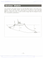
'Anchor Watch
The shallow and deep alarms of the MC 800 make it the ideal companion for an anchor watch. Simply set the alarms to the required
depths, make sure that the audio alarm is turned on, and your MC
800 will sound the alert if your anchor drags. See the diagram below
for a complete explanation.
21ft
30ft
-23
-
-----_._--
~
--
,--"",-
~
=-
=~c._~c
-=::::::
,=
-
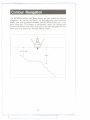
Contour Navigation
The MC 800's shallow and deep alarms are also useful for contour
navigation. By setting the alarms for the maximum and minimum
depths you wish to remain between, the MC 800 will alert you if you
stray from this. This feature is particularly useful for fishing near
continental shelves and other drop oHs, since your MC 800 will alert
when you drift away from the best fishing waters.
~
SHALLOW
1
DEEP
J
-24f
'..
~
I
c::::::::=:
---
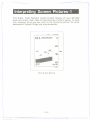
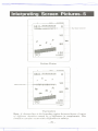
Interpreting Screen Pictures-1
The Super Twist Nematic Liquid Crystal Display of your MC 800
gives you sharp, clear, easy to read pictures of what's below. To help
you interpret what you see, refer to the following section for some
examples of typical things you may encounter.
OF
GAIN-
r.R r]
LI...
..
ALMIZOOM
DJ 1:1111111 DJ ID III r.:
I]
...................................
20
.:.LL.
.all::
J;rs.' .11
I
I
I I]
.':=1IL
I:i 1:1
....,~ 1"'1
...
I_I
lillllll
-5WP-
Normal Gain Setting
-25
-
,
t
.
""
....
~-
;;:;", ----
'V
'Interpreting Screen, Pictures-2
-F
GAIN-
ALMIZOOM
........................
... ... ... ... ... ... ... ...
...........
. .. .... ...................................
i.i
..
ii.i
~
. .." ....
..:.::::m.::m:.:.::m::m::::.m:m:m::::
.....
.....
...
i.ii.i
.. . .. ...
...
. .....
'...::...:
! i;:n
........
........
........
-SWP-
Gain Setting Too High
OF
GAIN
ALMIZOOM
...
....
...
... ...
... ...
... ...
. ...
.. ...
.. ...
... ...
... ...
... ...
... ...
...
. . .. .. ...................................
i
i.i
~
i.i
i.i
... ...........
.....
... . .
........................
.................................................
............................................
i ..i i
........
""""
........
........
::::sC'
.
-SWP-
Gain Setting Too Low
- 26-
.-.--------
~
.",
<::
--~---
-===
'~--.~
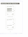
Interpreting Screen Pictures-3
OF
ALMIZOOM
GAIN
. .. ..
... ...
... ...
... ...
... ...
...
... ...
... ...
... ...
...
.. ...................................
....... ..
...
. . ..
i.i
I::I]
~
im.
.i--.
.Ii-i..
.i-i.
..
i.!!.!
........
!;in
. ..
........
........
... m..
-5WP-
Fast Sweep
GAIN
OF
m...
...
. .. ..
..
. . ..
ALMIZOOM
...
...
... ...
... ...
... ...
... ...
... ...
... ...
... ...
....... ........................................
i.i
..ii
i
~
.--.
.-.
.-.-.
'-in
.---.
..
.--.-
i.. i ,
. ..
m..
m
........
........
. ..
........
-5WP-
Slow Sweep
- 27-
r
-"'---'-"'--'---"""'=-=1
'
"
=t
-~-,-_.
"'_M"_,=~-
_.
~
-
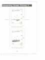
Interpreting Screen Pictures-4
ALMIZOOM
GAIN
OF
...
. ...
.. ...
.. ...
... ...
... ...
... ...
... ...
... ...
... ...
... ...
...
.......................................
..
....... ...
a::[5
.:i:.
Soft bottom
.
.-.
.-.
~
......
....
::m::iii
Ha rd bottom
. .....
...
. ...
!:e5]
........
........
-5WP-
Soft and Hard Bottom Echoes
GAIN -
'F
!:i i:i . [i
ALMIZOOM
,.,
:::.:::.:::.:::.:::.:::.:::.:::
i.. i.i
...
.
....
...
:ii:'
....
~
,
.. ...
5:e[5
........
........
. .....
-5WP-
Echo from Underwater Plants
-28
,
_'oM
-,.,
-.. --
-
-'--'-"'-'---'
'
----'--'
-:r
i
-:[
-==
-
~
Interpreting Screen Pictures-5
GAIN
OF
,.., "
,,"
",
"m
-
ALMIZOOM
...
m ..,
.., ..,
.., m
.., m
.., ..,
.., ..,
..,
..,
.., ..,
mm
m m
..
mm""..
.,
Surface Clutter
-::' ::'::'5 :5:5:':'::'5::5' :55':5'::':::5:::':' 5:
,, ....
, . ,,
i
..
..,
..,
~
,
ii,
,..., ,...,,
:.: :,:
,ii
,..,
.,, ......
. , ,,
,, , " ,
..," ...,
,..,..
,
.. ., ...,
"
...,.."
..".."
,..,
-SWP-
Surface Clutter
GAIN
OF
..,...
, "
m
"
-
ALMIZOOM
..,
.., ..,
.., m
m ..,
.., m
... m
... ..,
.., ..,
..,
. , ,. ,.,
,. ..m..m..mm
..
..,...,
...
,,
,,
,
,
m
Thermocline
i-.
,ii,
i
,,
"
, ..
...., ..,..
.. .
m,
",, , ,..,
ii i.
"
,..
:!;:=:
ii'
~
... ...
.....
.i,
:i!==:i
i
, ......
. , "
........
........
:m: :"':
:::: 5..,5
,.,
,
-SWP-
Thermocline
Note: A thermocline is the boundary region between layers of water
of different densities caused by a difference in temperature. This
condition can also occur with a difference in salinity.
-29 -
":J---
f
'
"
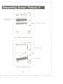
Interpreting Screen Pictures-6
GAIN
OF
ALMIZOOM
m
m... ..
... ......
... ... ...
... ......
m m ......
... ...
. m
..
...
.. ...................................
....
. .. ..
.......
...
..
.
n
.ii
.....
Bottom Echo
(First Reflection)
.. m
~
2nd
Refrection
Echo
... ...
. m..
........
........
.r C-5
11...1
-SWP-
First and Second Reflection Echoes
GAIN
OF
. .. ..
..
....
..
..........
-
ALMIZOOM
...
... ...
... ...
... ...
... ...
... ...
... ...
... ...
...
'" ..
..
m
...
..
..
.. .........
...
.....
.m ..
..
Shallow Alarm
~
.....
...
.....
.5;':':" .1;1"-1;;
.....
....
m..
...
....
; 11
i
. ....
...
....
m.
m....
... ....
Deep Alarm
mm
i::U
innUi
-swP-
Shallow and Deep Alarms
-30
-
"
~
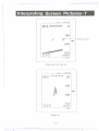
-----Interpreting Screen Pictures- 7
!:i I:!
ALMIZOOM
GAIN
OF
.[!
I.1
1'
m.:::.:::.:::.:::.:::.:::.:::':::
1:1i..
'l
I.
..
El
;""
Zoom Cursor
~
:' 1'1
'S
. 1.1.
..m
m
...............
..m
m m.
m m.
mm........
.m.............
.mm......
'"
m.........
...... .... .......
a:! 1.1 i:1
iiiilill
.:::..i. 1...1
-SWP-
Zoom set, but not on
'F
GAIN
... m ...
..
..
ALMIZOOM
m ...
... ...
... m
m m
m m
m m
m m
m
m
... ...
, ....
~
., ,-..
f~
....
..... .......
..... .......
...
, '"
........
........
-SWP-
Zoom on
-31
f
,-,
,-.- .--,--, .--
-
..'"_.--, .-' -,
'-'---' ",---,-.
"=-="1---------
~---
T
Interpreting
----
=
.,.."
Screen
'F
Picture~o-~
GAIN
.0
ALMIZOOM
........
. .... ......
..
......
.....
...
.......
..
..
..... ...
... ......
....
..
....
..
..
........
........
..
..
..
..
..
..
..
.......... ..
......
..
...... ..
.. ..
..
..
..
..
..
..
.. ......
........
~
....
......
........ ..............
..
..
.. ..
..
..
..
.. ..
..
........
..
..
..
..
..
..
............
.. ............
........
.. .. .. ........
-5WP-
DDM (Digital Display Mode)
-32
-
-------------
~
=-1
i
.-~.....
=
,_.~,.~
- ---
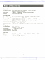
Specifications
General
Display type
Keypad
Power
Dot Matrix Graphic Super Twist Nematic
Liquid Crystal Display
Tactile Feedback Membrane Keypad
12V DC nominal
Operational
Depth Ranges 0'-15',0'-30',0'-60',0'-120',0'-240'
& 0'-480'
Transducer Frequency
200 KHz
Output Power 160W P-P (20W RMS) for 0'-15' and 0'-30' ranges
520W P-P (65W RMS) for all other ranges
Alarm Ranges Shallow - 3 to 480 feet
Deep - 480 to 3 feet
Zoom Width 15 feet on any depth range with one foot increment
Display
Dimensions
Dot Size
Dot Spacing
Backlighting
4.3"H x 3.3"
(109H x 83W m/m)
1.1 mm x 1.1mm
0.1 mm
by lamp
Physical
Size
Weight
7.7"W x 6.3"H x 1.9"0 (195W x 160H x 48 Dmm)
1.8 Ibs (800g)approx.
-33 =t
- - - -
- -- - - -.- -..-.-
- - -. - --~-
-
<:
--
....
r
Troubleshooti n9
Problem: Unit will not operate 1. Checkpower cord in-line fuse.
2. Check power connections.
3. Check if unit is turned on.
4. Check battery supply voltage.
Problem: Unit causes Interference
with radio reception -
1. Connect the power cable to a different circuit than the radio.
2.
Reroute cables well away from the radio.
Problem: No bottom display
1. Checkdepth range for
-
correct setting.
2. Check that transducer is connected.
3. Check for transducer cavitation (air gap under transducer during
high speed operation).
Problem: Excessive clutter on the display 1. Lower Gain setting.
2. Check for turbulence under transducer.
3. Check for mild cavitation under transducer.
4. Check for other depth sounders operating nearby.
-34-
===r
~
'=
7'~._~'
~
-=
~
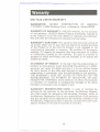
Warranty
ONE YEAR LIMITED WARRANTY
WARRANTOR:
UNIDEN
CORPORATION
OF AMERICA
(JlUNIDEN"), 6345 Castleway Court, Indianapolis, Indiana 46250.
ELEMENTS OF WARRANTY: UNIDEN warrants, for the duration
of this warranty, UN IDEN Marine Products (hereinafter referred to
as the Product) to be free from defects in materials and craftsmanship with only the limitations or exclusions set out below.
WARRANTY DURATION: This warranty shall terminate and be of
no further effect one (1) year after the date of the original purchase
of the Product or at the time the Product is (A) damaged or not
maintained as reasonable or necessary, (B) modified, (C) improperly
installed, (D) repaired by someone other than warrantor for a defect
or malfunction covered by this warranty, (E) used in a manner or
purpose for which the Product was not intended, or (F) sold by the
original purchaser.
STATEMENT OF REMEDY: In the event that the product does not
conform to this warranty at any time while this warranty is in effect,
warrantor will repair the defect and return it to you without charge
for parts, service, or any other cost incurred by warrantor or its representatives in connection with the performance of this warranty.
THE WARRANTY DOES NOT COVER OR PROVIDE FOR THE
REIMBURSEMENT OR PAYMENT OF INCIDENTAL OR CONSEQUENTIAL DAMAGES. Some states do not allow this exclusion
or limitation of incidental or consequential damages so the above
limitation or exclusion may not apply to you.
WARRANTY REGISTRATION CARD: In order to facilitate the
servicing of this warranty by the warrantor, the Warranty Registration Card should be returned to the warrantor. However, return of
the Warranty Registration Card is not a precondition of this warranty,
and this warranty will be observed by the warrantor whether or not
the Warranty Registration Card is returned, provided that other satis-
factory evidence of the date of purchase is provided.
-35 -
J
"'-'--'-"""-"""'-""'
"
"'
o""""'-=f---------
f
,--...
-'-"-'~~'
=",
---
~
Warranty.
PROCEDURE FOR OBTAINING PERFORMANCE OF WARRANTY: In the event that the Product does not conform to this warranty,
the Product should be shipped or delivered, freight prepaid, to warrantor at UNIDEN Customer Service Center, 9340 Castlegate Drive,
Indianapolis, IN 46256 with evidence of original purchase.
LEGAL REMEDIES: This warranty givesyou specific legal rights,
and you may also have other rights which vary from state to state.
This warranty is void outside of the United States of America.
-36 -
~=
".'
=-r-I
-====
--
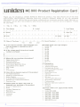
uniden MC800 Product Registration Card
Thank you for choosing a Uniden @ Marine Electronic product. You have chosen one of the most
sophisticated,
technologically
advanced electronic
products
available. Please fill out the requested
information
on th is card so that we can better understand
ou r customers and thei r needs. With th is information,
we can plan new products,
for your help.
1. 0 Mr. 2. 0 Mrs.
advertising,
and guide our customer
service programs.
3. 0 Ms. 4. 0 Miss
6. Initial
5. First Name
l
7. Last Name
I I I
9. Apt. No.
I I I
I
8. Street
I I I
11. State
10. City
I
I
I
13. Date of Purchase
JI
I
Ut
day
j 14.
16.lf No, please specify brand and model
number pruchased.
A
B
C
17.Where did you purchase the product?
0 Department Store
0 Discount Store
0 Catalog Showroom
0 Electronics Specialty Store
0 Local Electronics
Dealer
0 Mail Order
0 Gift
0 Truck Stop
How did you become aware of this product
TV Advertisement
Magazi ne Advatisement
Store Display
Friends Recommendation
Salesperson's
Recommendation
Previous Use
19. Please check the factor that most influenced your purchase of the product.
0 Style or Appearance
0 Price
Uniden Reputation
Warranty
Previous Use
Features
Qual ity
Serial Number
LJ I
20.
0
0
0
0
0
0
0
0
0
0
0
Please check your age category
Under 20
20-25
26-30
31-35
36-40
41-45
46-50
51-55
56-60
61-65
66-over
21.0ccupation
0 Homemaker
0 Teacher/Educator
0 Professional Driver
0 Executive/Administrator
0 Civil Servant
0 Sales/Marketing
0 Clerical
0
0
0
0
0
0
0
0
Farmer/Agriculture
Military
Technical/Professional
Business/Professional
Craftsworker
Machine Operator/Laborer
Retired
Student
22. Please check your
income.
0 Under $10,000
- $19,999
0
$10,000
0
$20.000
- $29,999
0
$30,000
- $39,999
0
$40,000
- $49,999
0
$50;000
- $59,999
0 $60,000 & over
=r
I
year
15.ls this the first Uniden LCD Fishfinder you
have purchased or received as a gift?
0 Yes 0 No
0
0
0
0
0
12. Zip
LJ
moo
18.
0
0
0
0
0
0
Thanks
approximate
family
. ---""
T
<:
;-.
~-
---.--
--
-==
-=--=-
- ~~-""
Place
First Class
Stamp
here
uniden@
6345 Castleway Court
Indianapolis, IN 46250
Attn : MC Market Research
Department
Please do not send any products or service related correspondence to th is address
--------------------------------------------------------------------------------------------------------------25. What types of credit cards do you use?
D American Express, Diner's 'Clab, Carte
Blanche
D Bank Cards (Master Card, Visa, etc.)
D Gasoline Card, NameD Department Store Card
D None of the above
23. What type of car (5) do you drive?
D Compact
D Mid Size
D
D
D
D
D
Sports
Full Size
Station Wagon
Van
Recreational
Vehicle
D Specialty
D Motor Cycle
D Pick Up
24.
D
D
D
D
D
D
D
D
D
D
D
D
D
D
D
What magazine(s) do you read?
Road & Track
Car & Driver
Motor Trend
Auto Week
American Trucker
Road King
Playboy
Sports Illustrated
Penthouse
Time
Newsweek
Popular Science
Popular Mechanics
Consumer Reports
People
..
Printed
@ 1987 Uniden Corporation of America
. - - - - - - i ~~t;~~ti~-";s':-
F ili '~~t
'b~;h
~id;~
~-f- ~~;d'-
F-~Id-
~~-
d~-tt~d-li~~:
-F~id
in Japan
- - - - -- -- - - - -- - - - - - pi~~;~ .F~id H~;; - - - - - - - - :
overlap and seal with glue or paste. Affix postage and mail.
,.---...
.~
~,
\
t
uniden
6345 Castleway Court
Indianapolis, IN 46250
Printed in Japan
-----...
:r
~