1
INSTALLATION
INSTRUCTION-50 Hz
GENERAL. . . . . . . . . . . . . . . . . . . . . . . . . . . . . . . . . . . . . . . . . . 3
NOTES, CAUTIONS AND WARNINGS . . . . . . . . . . . . . . . . . . . 3
INSPECTION . . . . . . . . . . . . . . . . . . . . . . . . . . . . . . . . . . . . . . . 3
SPLIT-SYSTEM
EVAPORATOR BLOWER
MODELS: LA300
LB360
LB480
LB600
(50 Hz)
NOMENCLATURE . . . . . . . . . . . . . . . . . . . . . . . . . . . . . . . . . . . 4
MAINTENANCE . . . . . . . . . . . . . . . . . . . . . . . . . . . . . . . . . . . . 19
SEE THE FOLLOWING PAGE FOR A COMPLETE TABLE OF
CONTENTS LISTING.
CAUTION:
READ ALL SAFETY GUIDES BEFORE YOU
START TO INSTALL YOUR UNIT.
SAVE THIS MANUAL
035-18902-000-A-0402
035-18902-000-A-0402
TABLE OF CONTENTS
GENERAL . . . . . . . . . . . . . . . . . . . . . . . . . . . . . . . . . . . . . . 3
NOTES, CAUTIONS AND WARNINGS . . . . . . . . . . . . . . . . 3
REPLACEMENT PARTS . . . . . . . . . . . . . . . . . . . . . . . . . . . 3
INSPECTION . . . . . . . . . . . . . . . . . . . . . . . . . . . . . . . . . . . . 3
LIMITATIONS . . . . . . . . . . . . . . . . . . . . . . . . . . . . . . . . . . . . 3
BLOWER MOTOR MOUNTING LOCATIONS . . . . . . . . . . . 6
LA300/LB360/LB480 MOTOR MOUNTING . . . . . . . . . 6
LB600 MOTOR MOUNTING . . . . . . . . . . . . . . . . . . . . . 6
MOTOR MOUNT ARRANGEMENTS . . . . . . . . . . . . . . . . . 7
LA300/LB360/LB480 MOTOR ARRANGEMENTS . . . . 7
ADDITIONAL MOTOR ARRANGMENTS FOR LA300/
LB360/LB480 . . . . . . . . . . . . . . . . . . . . . . . . . . . . . . 7
LB600 MOTOR ARRANGEMENTS . . . . . . . . . . . . . . . 8
RE-LOCATING THE LB600 MOTOR MOUNTING
PLATE . . . . . . . . . . . . . . . . . . . . . . . . . . . . . . . . . . . 8
ALTERNATE POSITION ONE . . . . . . . . . . . . . . . . . . . 8
ALTERNATE POSITION TWO . . . . . . . . . . . . . . . . . . . 8
ALTERNATE POSITION THREE . . . . . . . . . . . . . . . . . 8
AIR DISCHARGE CONVERSION . . . . . . . . . . . . . . . . . . . . 8
LA360/LB360/LB480 AIR DISCHARGE . . . . . . . . . . . . 8
LB600 AIR DISCHARGE . . . . . . . . . . . . . . . . . . . . . . 10
UNIT INSTALLATION . . . . . . . . . . . . . . . . . . . . . . . . . . . . 10
LOCATION . . . . . . . . . . . . . . . . . . . . . . . . . . . . . . . . . 10
RIGGING . . . . . . . . . . . . . . . . . . . . . . . . . . . . . . . . . . . 10
CLEARANCES . . . . . . . . . . . . . . . . . . . . . . . . . . . . . . 10
MOUNTING . . . . . . . . . . . . . . . . . . . . . . . . . . . . . . . . . 11
DUCT CONNECTIONS . . . . . . . . . . . . . . . . . . . . . . . . . . . 14
INSULATION . . . . . . . . . . . . . . . . . . . . . . . . . . . . . . . . 14
SUPPLY AIR DUCTS . . . . . . . . . . . . . . . . . . . . . . . . . 14
RETURN AIR DUCT ANGLES . . . . . . . . . . . . . . . . . . 15
DRAIN CONNECTIONS . . . . . . . . . . . . . . . . . . . . . . . 15
REFRIGERANT MAINS . . . . . . . . . . . . . . . . . . . . . . . . . . . 15
EVAPORATOR SECTION PIPING . . . . . . . . . . . . . . . 16
EXPANSION VALVE BULB INSTALLATION . . . . . . . 16
LA300 . . . . . . . . . . . . . . . . . . . . . . . . . . . . . . . . . . . . . 16
LB360/LB480/LB600 . . . . . . . . . . . . . . . . . . . . . . . . . . 16
BEARING ALIGNMENT: LB600 . . . . . . . . . . . . . . . . . . . . . 16
AIR SYSTEM ADJUSTMENT . . . . . . . . . . . . . . . . . . . . . . 17
TWIN BELT DRIVE ADJUSTMENT . . . . . . . . . . . . . . . . . . 17
ELECTRICAL CONNECTIONS . . . . . . . . . . . . . . . . . . . . . 17
MAINTENANCE . . . . . . . . . . . . . . . . . . . . . . . . . . . . . . . . . 19
LIST OF FIGURES
#
pg. #
1
2
PRODUCT NOMENCLATURE . . . . . . . . . . . . . . . . . . 4
LA300 AN LB360/LB480 FACTORY MOTOR
MOUNTING POSITION . . . . . . . . . . . . . . . . . . . . . 6
LB600 FACTORY MOTOR MOUNTING POSITION . 6
LB600 MOTOR MOUNT PLATE . . . . . . . . . . . . . . . . 6
LA300/LB360/LB480 MOTOR LOCATION A . . . . . . 7
LA300/LB360/LB480 MOTOR ARRANGEMENTS . . . 7
VERTICAL AIRFLOW ARRANGEMENTS . . . . . . . . . 9
HORIZONTAL AIRFLOW ARRANGEMENTS . . . . . . 9
3
4
5
6
7
8
2
LIST OF FIGURES (CONT.)
#
9
10
11
12
13
14
15
16
17
18
19
20
21
22
23
24
25
26
27
28
29
30
pg. #
LB600 AIRFLOW ARRANGEMENTS . . . . . . . . . . .
DETAILS FOR SECURING BOTTOM MOUNTING
SUPPORTS . . . . . . . . . . . . . . . . . . . . . . . . . . . . .
LA300/LB480/LB360 WEIGHT DISTRIBUTION . . .
LB600 WEIGHT DISTRIBUTION WITH
SUSPENSION APPLICATION . . . . . . . . . . . . . . .
DETAILS FOR SECURING SUSPENSION
CHANNELS . . . . . . . . . . . . . . . . . . . . . . . . . . . . .
SUGGESTED METHOD FOR CONNECTING
DUCTWORK . . . . . . . . . . . . . . . . . . . . . . . . . . . .
RECOMMENDED DRAIN PIPING . . . . . . . . . . . . . .
LB600 CENTER BEARING . . . . . . . . . . . . . . . . . . .
DOUBLE GROOVE PULLEY . . . . . . . . . . . . . . . . . .
UNIT DIMENSIONS - LA300, LB360, 480 . . . . . . . .
LA300 PIPING CONNECTIONS . . . . . . . . . . . . . . .
LB360 PIPING CONNECTIONS . . . . . . . . . . . . . . .
LB480 PIPING CONNECTIONS . . . . . . . . . . . . . . .
UNIT DIMENSIONS . . . . . . . . . . . . . . . . . . . . . . . . .
LB600 PIPING CONNECTIONS DETAIL . . . . . . . .
25-TON PRESSURE DROP VS. CFM ACROSS
INDOOR COIL . . . . . . . . . . . . . . . . . . . . . . . . . . .
30-TON - PRESSURE DROP VS. CFM ACROSS
INDOOR COIL . . . . . . . . . . . . . . . . . . . . . . . . . . .
40 TON - PRESSURE DROP VS. CFM ACROSS
INDOOR COIL (DOMESTIC) . . . . . . . . . . . . . . . .
40-TON - PRESSURE DROP VS. CFM ACROSS
INDOOR COIL (INTERNATIONAL) . . . . . . . . . . .
50 TON - PRESSURE DROP VS. CFM ACROSS
INDOOR COIL . . . . . . . . . . . . . . . . . . . . . . . . . . .
INDOOR UNIT WIRING DIAGRAM LB360, 480
& 600 . . . . . . . . . . . . . . . . . . . . . . . . . . . . . . . . . .
INDOOR WIRING DIAGRAM LA300 . . . . . . . . . . . .
10
12
12
13
14
15
15
17
17
22
23
23
23
24
24
25
25
26
26
27
28
29
LIST OF TABLES
#
pg. #
1
2
3
4
5
UNIT APPLICATION DATA . . . . . . . . . . . . . . . . . . . . . 4
PHYSICAL DATA . . . . . . . . . . . . . . . . . . . . . . . . . . . . . 5
UNIT MOUNTING DIMENSIONS . . . . . . . . . . . . . . . . 11
CORNER WEIGHTS . . . . . . . . . . . . . . . . . . . . . . . . . 11
ACCESSORY OPERATING WEIGHT DISTRIBUTION
(LBS) . . . . . . . . . . . . . . . . . . . . . . . . . . . . . . . . . . . 11
ELECTRICAL DATA . . . . . . . . . . . . . . . . . . . . . . . . . . 18
UNIT DRIVE DATA . . . . . . . . . . . . . . . . . . . . . . . . . . 19
UNIT BLOWER MOTOR DATA . . . . . . . . . . . . . . . . . 19
FAN PEFORMANCE DATA - 25-TON . . . . . . . . . . . . 20
FAN PEFORMANCE DATA - 30-TON . . . . . . . . . . . . 20
FAN PERFORMANCE DATA - 40 TON . . . . . . . . . . . 20
FAN PERFORMANCE DATA - 50 TON . . . . . . . . . . . 21
UNIT DIMENSIONS - LA300, LB360, LB480 . . . . . . . 22
6
7
8
9
10
11
12
13
Unitary Products Group
035-18902-000-A-0402
GENERAL
REPLACEMENT PARTS
The LA and LB evaporator units are designed for use with the
HA/HB Series condensing units.Units are designed to match
up with LA/LB series Evaporator Blowers to meet ASHRAE
90.1 standards.
Refer to parts manual for complete listing of replacement
parts on this equipment. The above forms and all other forms
referenced on this instruction may be ordered from;
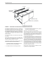
Each unit consists of a coil section and a blower section that
are factory assembled and shipped as shown in figures 3 and
4. These sections may be rearranged in the field for other air
discharge patterns. See figures 7, 8 and 9.
Standard Register
2101 W. Tecumseh Road
Norman, OK 73069
Tel: (405) 292-1127
Fax: (405) 364-7869
INSPECTION
The LA and LB evaporator units have 24 volt normally closed
solenoid valves to match the 24-volt control circuits of the
SimplicityTM control board in the HA300 as well as the
HB360, HB480 and HB600 condensing units.
As soon as a unit is received, it should be inspected for possible damage during transit. If damage is evident, the extent of
the damage should be noted on the carrier's freight bill. A
separate request for inspection by the carrier's agent should
be made in writing.
NOTES, CAUTIONS AND WARNINGS
LIMITATIONS
Installer should pay particular attention to the words: NOTE,
CAUTION and WARNING. Notes are intended to clarify or
make installation easier. Cautions are given to prevent
equipment damage. Warnings are given to alert installer that
personal injury and/or equipment damage may result if installation procedure is not handled properly.
This unit must be installed in accordance with all national and
local safety codes. If no local codes apply, installation must
conform to the appropriate national code. The unit is
designed to meet National Safety Code Standards. If
components are to be added to a unit to meet local codes,
they are to be installed at the dealer's and/or the customer's
expense. See Table 1 for unit application data.
Unitary Products Group
3
035-18902-000-A-0402
PRODUCT NOMENCLATURE
YORK OUTDOOR SPLIT CONDENSING UNITS AND HEAT PUMPS
L A 300 C 00 A 7 A AA 1 A
L
Model Number
Description
Product Category
A
Product Identifier
300
Nominal Cooling
Capacity
MBH
Model #
C
00
A
7
A
AA
1
A
Options
L = Air Handling Unit F = Air Handling Unit - Heat Pump
A = R-22 Standard Efficiency 2-Pipe
B = R-22 Standard Efficiency 4-Pipe
300 = 25 Ton *
360 = 30 Ton *
480 = 40 Ton *
600 = 50 Ton *
C = Cooling Only
00 = No Heat Installed
Heat Type
Nominal Heating
Capacity
Airflow Options
Voltage
Installation Options
Additional Options
Product Generation
Product Style
A = None
7 = 380/415-3-50
A = None
AA = None
1 = First Generation
A = Style A
2 = Second Generation
B = Style B
*NOT AVAILABLE IN HEAT PUMP
FIGURE 1:
PRODUCT NOMENCLATURE
NOTE: LB600 Indoor Unit matches with both HB480 and
HB600 Outdoor Condensing Units for maximum efficiency.
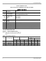
TABLE 1: UNIT APPLICATION DATA
Entering Air Temperature Degrees °F
Supply Air Range CFM
Cooling
DB/WB
Heating DB*
Model
Power Supply Voltage
Min.
Max.
Min.
Max.
Min.
Max.
Min.
Max.
LA300
380/415-3-50
342
456
8,000
12,000
65/57
95/72
40
77
LB360
380/415-3-50
342
456
10,000
14,000
65/57
95/72
40
77
LB480
380/415-3-50
342
456
12,800
19,200
65/57
95/72
40
77
LB600
380/415-3-50
342
456
16,000
24,000
65/57
95/72
40
77
*.
4
Voltage Variation
Heating Min/Max temperatures apply to steam and hot water coils. NOTE: Do not apply steam to hot water coils.
Unitary Products Group
035-18902-000-A-0402
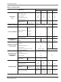
TABLE 2: PHYSICAL DATA
MODEL
DESCRIPTION
LA300
LB360
LB480
LB600
4 x 40
4 x 40
4 x 50
4 x 62
93
93
96
96
Face Area, Feet2
25.8
25.8
33.3
41.3
Tube (copper) OD, Inches
3/8
3/8
3/8
3/8
Fins (Aluminum) per 1 inch
16
16
16
16
7/8
7/8
7/8
7/8
2 1/8
1 1/8
1 3/8
2 1/8
Rows Deep X Rows High
Finned Length, Inches
EVAPORATOR
COIL
Piping Connections,
Inches
CENTRIFUGAL
BLOWERS (2 PER UNIT)
FILTERS (THROWAWAY)
Liquid, Inches
Suction, Inches
Diameter X Width, Inches (Forward Curved)
Size and Quantity Per
Model, Inches
18 x 18
16 x 20 x 2
-
6
-
20 x 20 x 2
-
3
-
20 x 22 x 2
-
-
-
16 x 25 x 2
-
-
6
20 x 25 x 2
10
6
3
25 x 25 x 2
-
-
6
34.7
42.6
53.1
Total Face Area / feet2
OPERATING CHARGE
(LBS R-22)
System 1
49.65
30.08
37.83
46.59
System 2
-
30.08
37.83
46.59
1/2
1/2
1/2
2
2
2
12
12
8
21.2
27.2
27.2
Tube (copper) OD, Inches
Rows Deep
DRAINABLE HOT WATER
COIL ACCESSORY
Fins (Aluminum) per 1 inch
Face Area, Feet
2
Connections (Supply & Return), Inches
Tube (copper) OD, inches
NON-FREEZE, STEAM
DISTRIBUTING COIL
ACCESSORY
1 5/8 OD (Copper)
1 (Outside) 5/8 (Inside)
1
Fins (Aluminum) per 1 inch
8
N/A
Face Area, feet2
18.2
Inlet
2
Outlet
1-1/2
Basic Unit (Less Motor & Drive)
980
980
1260
1474
Shipping Weight (lbs)
1180
1180
1510
-
Operating Weight (lbs)
1125
1146
1426
1640
Hot Water Coil
150
150
190
190
Steam Coil
160
160
-
-
117 (5hp)
117 (5hp)
-
-
120 (7.5hp)
120 (7.5hp)
120 (7.5hp)
141 (10hp)
-
141 (10hp)
141 (10hp)
-
Accessories
Blower Motor (1500 RPM)
Unitary Products Group
1 3/8 OD (Copper)
Rows Deep
Connection, (Brass)
Inches (NPTE)
COMPONENT WEIGHT
20 x 18
5
035-18902-000-A-0402
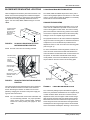
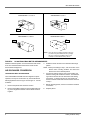
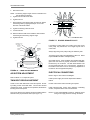
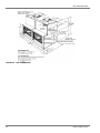
BLOWER MOTOR MOUNTING LOCATIONS
LA300/LB360/LB480 MOTOR MOUNTING
Units are shipped from the factory less motor and drives. The
blower motor and drive packages are ordered and shipped
separately for field mounting. However, the units are shipped
with the motor mounting assembly installed as shown in
Figure 2 for the LA300, LB360, LB480 and Figure 3 for the
LB600.
The LA300, LB360 and LB480 ship from the factory with a
motor mounting adapter plate for use with the 7.5 and 10 HP
motors. If a 5 HP motor is used, the adapter is not necessary
and should be removed and discarded.
The motor mounting plate will accommodate a 10 or 15 HP
motor. One set of boltholes is provided on each end of the
motor mounting plate for either motor. The motor mounting
plate can be raised or lowered to any position on the adjustment screws to adjust the belt tension for the various pulley
settings to cover the complete range of blower speeds.
OTOR MOUNTING
HANNELS AND
OUNTING PLATE
RE ALWAYS
HIPPED IN THIS
OCATIO N
FIGURE 2:
LB600 MOTOR MOUNTING
LA300 AN LB360/LB480 FACTORY
MOTOR MOUNTING POSITION
NOTE: The 5HP motors are not inherently protected.
A lte r n a tiv e P o s itio n
1 F o r P iv o t B o lts
A lte r n a te
P o s itio n 3
F o r P iv o t B o lts
The physical size of the 15 HP motor reduces the adjustment
range of the motor mounting plate. To maximize this amount
of adjustment, one set of boltholes is provided near the
adjustment screws on each end of the motor mounting plate
(refer to Figure 5).
For some motor/blower wheel arrangements, however, the
motor cannot be mounted in these bolt holes because the
motor terminal box would interfere with one of the blower section panels. To make these motor/blower wheel arrangements possible, a second set of boltholes is provided near
the pivot bolts on each end of the motor mounting plate.
1 5 H P
A lte r n a tiv e P o s itio n
2 F o r P iv o t B o lts
1 0 H P
1 5 H P
1 5 H P
A d ju s tm e n t
S c re w (2 )
M o to r M o u n tin g P la te
( S ta n d a r d L o c a tio n
a s S h ip p e d )
FIGURE 3:
1 5 H P
P iv o t B o lt ( 2 )
LB600 FACTORY MOTOR MOUNTING
POSITION
A d ju s tm e n t
S c r e w H o le s
1 5 H P
1 0 H P
1 5 H P
The motors used with the evaporator blower are 3-phase and
can drive the blower wheels from either end of the blower
section. Reversing the direction of rotation can be accomplished by changing the connection of the power supply wiring at the motor terminal box.
NOTE: The 7.5-15 HP blower motors have solid bases and
are not inherently protected. For proper operation,
these motors require overload heater elements.
Please see curent product price pages for overloads.
6
FIGURE 4:
LB600 MOTOR MOUNT PLATE
The 15 HP drive package requires two different lengths of
belts to vary the blower wheel RPM over the complete range
of rated conditions. When the motor is mounted near the
adjustment screws, the two lengths of belt are interchangeable except for the higher and lower limits of blower wheel
RPM. When the motor is mounted near the pivot bolts, the
shorter length of belt is recommended for the higher blower
wheel Rpm's and the longer length of belt is recommended
for the lower blower wheel Rpm's. See Page 7 for the recom-
Unitary Products Group
035-18902-000-A-0402
LB600 MOTOR ARRANGEMENTS
mended blower motor locations.
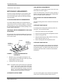
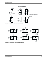
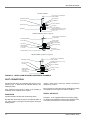
MOTOR MOUNT ARRANGEMENTS
The motor mounting arrangement can be changed to allow
motor access based on the airflow arrangement required.
The recommended motor location for each blower arrangement is as follows.
The LB600 unit is shipped with the motor mount in the standard location as shown in Figure 3.
If this is the desired position, the motor mounting assembly is
already in the correct position and the motor and drive package can be installed without modifications.
RE-LOCATING THE LB600 MOTOR MOUNTING
PLATE
LA300/LB360/LB480 MOTOR ARRANGEMENTS
The LA300, LB360 and LB480 units are shipped with the
motor mount in location A as shown in Figure 5. If this is the
desired position, the motor mounting assembly is already in
the correct position and the motor and drive package can be
installed without modifications.
ADDITIONAL MOTOR ARRANGMENTS FOR LA300/
LB360/LB480
Move the entire motor amounting assembly (both the mounting plate and the channels) so that the mounting plate will be
in the correct location.
M O T O R
M O T O R
M O U N T IN G
P L A T E
FIGURE 5:
M O T O R
M O U N T IN G
C H A N N E L S
The motor mounting plate can be re-located in three alternate
positions:
ALTERNATE POSITION ONE
For locating motor mounting plate in alternate position one,
see Figure 4 and re-locate as follows:
1.
Remove pivot bolts from the mounting plate.
2.
Remove the mounting plate from the adjustment screws.
3.
Rotate mounting plate 180.
4.
With pivot bolts removed in Step 1 fasten the mounting
plate to alternate position No. one.
5.
Fasten mounting plate to the adjustment screws.
ALTERNATE POSITION TWO
The motor mounting plate, the pivot bolts and the adjustment
screws can be moved into a position similar to the one shown
as standard in Figure 4 but under the other blower scroll. The
framework under each blower scroll has the same bolthole
arrangement.
LA300/LB360/LB480 MOTOR
LOCATION A
1.
Rotate the motor mounting plate 180 degrees on the
mounting channels. (For locations B, and D only! Do not
rotate the plate for location C or E.)
2.
Install the motor and drive package.
NOTE: The blower section must be lifted off the evaporator
section to gain access to the mounting channel fasteners. Since these sections have to be repositioned for the arrangements 2 through 10 and 12 of
Figure 7, the motor mounting assembly should be
relocated before the two sections are rejoined.
ALTERNATE POSITION THREE
Unitary Products Group
The motor mounting plate, the pivot bolts and the adjustment
screws can be moved into a position similar to the one
7
035-18902-000-A-0402
ARRANGEMENT 2, 6 OR 7
ARRANGEMENT 1, 4, 8 OR 11
SEE
NOTES
A
B
C
D
SEE
NOTES
ARRANGEMENT 9 OR 12
ARRANGEMENT 3, 5 OR 10
SEE
NOTES
SEE
NOTES
C
E
NOTE: Since the motor mounting assembly cannot be
secured to the panel with the blower openings,
the motor cannot be installed in either of the
normally recommended bottom positions.
FIGURE 6:
LA300/LB360/LB480 MOTOR ARRANGEMENTS
detailed in alternate position one but behind the other blower
scroll. The framework behind each blower scroll has the
same bolthole arrangement.
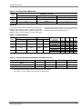
AIR DISCHARGE CONVERSION
LA360/LB360/LB480 AIR DISCHARGE
The LA300 LB360 and LB480 units are shipped for upflow
operation, but may be converted for any of the illustrated air
discharge patterns shown in Figure 8 and Figure 9. Convert
as follows:
1.
Remove the panels from the blower section.
2.
Remove the Phillips machine screws located inside casing corner angles that hold the coil and blower sections
together.
8
3.
Rotate the blower section for the desired air discharge
pattern.
NOTE: Before proceeding to step 4, see the section on the
blower motor mounting locations and mount the
blower motor in the desired position.
4. If accessory heating coils are used, mount heating coil
between cooling coil and blower sections. Screw fastening locations are the same for all sections and heating
accessories. If heating coils are not used, fasten coil
section to blower section with machine screws removed
in step 2.
5.
Before replacing panels, see duct connections and drain
connections.
6.
Replace panels.
Unitary Products Group
035-18902-000-A-0402
VERTICAL ARRANGEMENTS
1
AIR
BLOWER
3
2
AIR
AIR
AIR
EVAPORATOR
COIL
AIR
A IR
*
AIR
4
* IF REQUIRED, SOME AIR CAN
BE BROUGHT THROUGH THE
BOTTOM OF THE EVAPORATOR
SECTION.
*
*
5
6
AIR
AIR
AIR
*
*
*
VERTICAL AIRFLOW ARRANGEMENTS
7
AIR
FIGURE 7:
AIR
AIR
8
9
AIR
AIR
AIR
AIR
11
AIR
AIR
AIR
AIR
10
12
AIR
AIR
AIR
FIGURE 8:
HORIZONTAL AIRFLOW ARRANGEMENTS
Unitary Products Group
9
035-18902-000-A-0402
LB600 AIR DISCHARGE
The LB600 blower and coil section are shipped separately
and must be joined in the field. The blower section can be
mounted either above the coil for a vertical positioning or
beside the coil for horizontal positioning. Both vertical and
horizontal positions can be arranged for upward, downward,
or horizontal air discharge.
NOTE:
Ductwork should never be used to support the
blower section. Refer to duct connection for more
information
UNIT INSTALLATION
LOCATION
The evaporator blowers are not designed for outdoor installation. They must be located inside the building structure,
either inside or outside the conditioned space where they are
protected from rain and other such moisture.
1
2
3
The unit should be located as close to the condensing unit as
practical and positioned to minimize bends in the refrigerant
piping.
Units being installed vertically or horizontally can be set
directly on a floor or platform, or supported by metal or
wooden beams.
FIGURE 9:
4
5
6
7
LB600 AIRFLOW ARRANGEMENTS
The coil section and the blower section may be assembled
together as shown in Figure 9. All arrangements may be by
rearranging the panels as shown.
When arranged vertically (Figure 9, arrangements 1 through
3), the LB600 can be set directly on any floor or platform that
is capable of supporting its weight.
When arranged horizontally (Figure 9, arrangements 4
through 7), the evaporator coil section can be set directly on
the floor, but a 9" support is required under the blower section
to stabilize the unit. The support should extend the full width
of the blower section and be located under the edge away
from the evaporator coil section. If the unit does not have to
be secured to the platform, the 9" support will not have to be
bolted to either the blower section or the floor.
The evaporator blower arrangement 7 shown in Figure 9 is
not recommended for bottom support due to interference with
the ductwork connection.
10
Units being installed horizontally (LA300, LB360 & LB480
only) can be suspended from above as shown in figure 12.
Refer to form 035-18501-000 for more information on the
installation of the suspension accessory and for the individual
load on each hanger rod.
RIGGING
Care must be taken when moving the unit. Do not remove
any packaging until the unit is near the place of installation.
SPREADER BARS SHOULD BE USED BETWEEN THE
SLINGS TO PREVENT CRUSHING THE UNIT FRAME OR
PANELS. When preparing to move the unit, always determine the center of gravity of the unit in order to equally distribute the weight. Rig the unit by attaching chain or cable
slings around the bottom skid. A lift truck may be used to
raise a unit to a suspended location. Refer to Table 2 for the
total unit operating weight.
CLEARANCES
A 25-inch clearance is required on the end with the piping
connections and the supply air blower motor to properly service and maintain the unit and to replace the filters.
Some clearance will also be required for the duct and power
wire connections. A clearance equal to the unit width is
required on one end of the unit if the blower shaft or evaporator coil is to be replaced without moving the unit.
Unitary Products Group
035-18902-000-A-0402
TABLE 3: UNIT MOUNTING DIMENSIONS
DIMENSIONS, INCHES
LA/LB
UNIT
300
A
69-1/4
B
49-1/16
C
26-5/8
360
69-1/4
49-1/16
26-5/8
480
84
50-9/16
34
MOUNTING
The evaporator blower may be suspended from the joists with
isolation type hangers or hooks. Suspension accessory
1HH0403, which includes three suspension channels and
hardware, may be ordered separately. The channels extend
across the evaporator coil section, the heating coil section (if
included) and the blower section. Each channel is to be
bolted to each section as shown in Figure 10.
TABLE 4: CORNER WEIGHTS
UNITMODEL
Unit Weight
Shipping
Operation
Unit Dimensions
Length
Width
LA300
1180
1125
110.46
88.46
LB360
1180
1146
110.46
88.46
LB480
1510
1426
128.46
88.46
LB600
TBD
1640
128.46
88.46
Configuration
HORIZONTAL
VERTICAL
HORIZONTAL
VERTICAL
HORIZONTAL
VERTICAL
HORIZONTAL
VERTICAL
A
289
274
330
318
401
374
TBD
TBD
B
333
316
380
366
478
445
TBD
TBD
C
299
316
251
265
343
376
TBD
TBD
D
260
274
218
231
288
315
TBD
TBD
TABLE 5: ACCESSORY OPERATING WEIGHT DISTRIBUTION (LBS)*
LA300
LB360
LB480
LB600
25
25
30
45
HOT WATER COIL
35
35
45
35
STEAM COIL 1 ROW
30
30
35
50
ACCESSORY
†
BASE
*.
These weights should be added to each point load (W1 through W6) in table 5.
†.
This accessory can only be applied on units installed in the vertical position.
Unitary Products Group
11
035-18902-000-A-0402
NOTE: The following illustration shows how the channels
should be secured to the unit using the hardware
provided with the suspension accessory.
(2) 9/16 HOLES FOR 1/2
HANGER RODS
SUSPENSION
CHANNEL
5/16 NUT,
LOCKWASHER,
FLATWASHER
3
5/16 NUT,
FLATWASHER
3/8 NUT (USED
AS SPACER)
UNIT PANEL
5/16 BOLT,
FLAT-WASHER
SIDE
PANEL
FIGURE 10:
UNIT ANGLE
DETAILS FOR SECURING BOTTOM MOUNTING SUPPORTS
A
W4
VERTICAL LA300, LB360, LB480
UNIT SUPPORTED FROM BELOW
B
B
W5
W1
3
W2
BLOWER
SECTION
1-1/2
HORIZONTAL
LEU360 OR 480
UNIT SUSPENDED
FROM ABOVE 3
W6
BLOWER
SECTION
EVAP.
COIL
SECTION
EVAP. COIL W3
SECTION
HEATING COIL 2
W3
W2
SUSPENSION
ANGLES 1
C
W1
W5
W4
FIGURE 11:
12
1
The same channels can be used in either position. When used to
support at vertical unit, these channels should be cut to match the
bottom dimension of the evaporator coil section.
2
The suspension channels have two sets of mounting holes to
accommodate horizontal units with or without a heating coil. On
a horizontal unit without a heating coil, the suspension channels
will extend 3" beyond both ends of the unit.
3
The same channels can be used to support a horizontal, floormounted unit from below.
4
After these bottom channels are cut per Note 1, a new hole will have
to be drilled at the cut end if the unit is to be mounted on isolators.
4
W6
B
B
LA300/LB360/LB480 WEIGHT DISTRIBUTION
Unitary Products Group
035-18902-000-A-0402
D = 2 9 5 L B S .
E = 3 0 0 L B S .
A = 2 7 5 L B S .
S U S P E N S IO N
C H A N N E L S
1
B = 2 8 0 L B S .
1
2
F = 3 1 0 L B S .
2
2
1
2
C = 2 8 5 L B S .
A IR
IN
B L O W E R S E C T IO N
H E A T IN G
C O IL (A C C E S S O R Y )
E V A P O R A T O R C O IL S E C T IO N
FIGURE 12: LB600 WEIGHT DISTRIBUTION WITH SUSPENSION APPLICATION
The weights for the LB600 shown in Figure 12 include only
the evaporator coil section, the blower section with a 10HP
motor and the suspension accessory. Add the weights listed
for a horizontal arrangement in Table 2 to determine the
weight distribution of the unit with accessories. See Figure
13 for details on connecting the center channel to the unit at
points one and two.
The weights are located 5" from both ends of each suspension channel.
When arranged horizontally (see Figure 9) the LB600 evaporator blower can be suspended from overhead joists with
hanger rods using the suspension accessory.
The suspension channels require no drilling or cutting. Each
channel has enough holes in its bottom flange for:
1.
Four bolted connections to the evaporator coil section.
(Only two are used on the outside supports)
2.
One bolted connection to the heating coil section.
Unitary Products Group
3.
Four bolted connections to the blower section. (Only two
are used on the outside supports)
See Figure 13 for the bolted connection in detail.
When the heating section is not included, each channel will
extend 3" beyond the front and the rear of the unit. Boltholes
in the bottom flange of each channel will still align with the
holes provided in the top framework of the evaporator coil
section and the blower section.
For both outside channels and for the 1" locations on the center channel, the bolted connections are to be made where the
top sheet metal panels are attached to the unit framework.
The ¼" screws and cage nuts must be removed and may be
discarded. For the 2" locations on the center channel, the
bolted connections are to be made through the knockouts in
the top sheet metal panels. 5/16" cage nuts are provided in
the unit framework under these knockout locations. Note that
these cage nuts are part of the basic unit. They are not supplied with the suspension accessory.
Refer to Figure 12 as well as Table 3 and Table 4 for mounting details and unit weight distribution.
13
035-18902-000-A-0402
O U T S ID E C H A N N E L
9 /1 6 " H O L E F O R 1 /2 " H A N G E R
(2 P E R C H A N N E L )
S U S P E N S IO N C H A N N E L
5 /1 6 -1 8 " H E X N U T
5 /1 6 -1 8 " H E X N U T
L O C K W A S H E R
R O D
9 /1 6 " F L A T W A S H E R
S P A C E R
(3 /8 " L O N G )
T O P P A N E L
9 /1 6 " F L A T W A S H E R
S ID E P A N E L
M A C H IN E S C R E W
(5 /1 6 -1 8 X 1 -1 /2 L G )
O U T E R F R A M E O F U N IT S E C T IO N
(1 -3 /4 " X 1 -3 /4 ")
C E N T E R C H A N N E L ( L o c a tio n " 1 " F ig u r e 6 )
9 /1 6 " H O L E F O R 1 /2 " H A N G E R
(2 P E R C H A N N E L )
S U S P E N S IO N C H A N N E L
5 /1 6 -1 8 " H E X N U T
5 /1 6 -1 8 " H E X N U T
L O C K W A S H E R
9 /1 6 " F L A T W A S H E R
T O P P A N E L
S P A C E R
C E N T E R F R A M E
O F U N IT S E C T IO N S
(2 1 /8 " X 3 /8 ")
M A C H IN E S C R E W
R O D
(3 /8 " L O N G )
T O P P A N E L
9 /1 6 " F L A T W A S H E R
(5 /1 6 -1 8 X 1 -1 /2 L G )
C E N T E R C H A N N E L ( L o c a tio n " 2 " in F ig u r e 6 )
S U S P E N S IO N C H A N N E L
9 /1 6 " H O L E F O R 1 /2 " H A N G E R
(2 P E R C H A N N E L )
M A C H IN E S C R E W
9 /1 6 " F L A T W A S H E R
T O P P A N E L
C E N T E R F R A M E
O F U N IT S E C T IO N S
(2 1 /8 " X 3 /8 ")
R O D
(5 /1 6 -1 8 X 1 -1 /2 L G )
L O C K W A S H E R
9 /1 6 " F L A T W A S H E R
S P A C E R
(1 /2 " L O N G )
T O P P A N E L
5 /1 6 -1 8 " C A G E N U T
FIGURE 13: DETAILS FOR SECURING SUSPENSION CHANNELS
DUCT CONNECTIONS
Ductwork should always be suspended with hangers or supported by legs. It should never be fastened directly to the
building structure.
Allow clearance around ducts for safety in the handling of
heated air and for insulation when required.
INSULATION
Ductwork insulation should meet the following criteria:
Be used when ducts pass through an unconditioned space in
the cooling season or through an unheated space during the
heating season.
14
Include a vapor barrier around the outside to prevent the
absorption of moisture.
Be no less than 2 inches thick with the weatherproof coating
when applied to ducts exposed to outdoor conditions.
SUPPLY AIR DUCTS
See Figure 14 for suggested method of connecting supply
air ductwork. Non-flammable material collars should be used
to minimize the transmission of noise and/or vibration.
Unitary Products Group
035-18902-000-A-0402
DUCT
TRANSITION
NON-FLAMMABLE
COLLAR
DUCT
24"
AIR
OUTLET
BLOWER
GASKETS
(BY INSTALLER)
FLANGED DUCT
CONNECTION
(FIELD
FABRICATED)
FIGURE 14: SUGGESTED METHOD FOR CONNECTING DUCTWORK
RETURN AIR DUCT ANGLES
Return air duct angles are shipped turned in. They are
intended to be unscrewed and turned for connection of ductwork. The return air grille accessory attaches in the same
manner as the panels.
DRAIN CONNECTIONS
All drain lines MUST be trapped and located so they will not
be exposed to freezing temperatures.
The evaporator blower has 7/8" OD steel condensate stub at
each end of a single drain pan. Both ends are closed with
plastic caps. A plastic ell with clamps is provided. Attach the
ell to the desired end and run a full size 7/8" drain line to the
nearest drain facility. Seal the cap at the unused end with
suitable mastic.
Drain piping should be constructed as shown in Figure 15.
The 3-inch dimension must equal or exceed the negative
static pressure developed by the supply air blowers. If it does
not, the condensate will not drain properly and may overflow
the drain pan. The trap must be at least 2-inches deep to
maintain a water seal under all operating conditions, especially when the blowers are starting.
Unitary Products Group
FIGURE 15: RECOMMENDED DRAIN PIPING
REFRIGERANT MAINS
Hard drawn copper tubing should be used where no appreciable amount of bending around pipes or other obstructions
is necessary. Use long radius ells wherever possible. If soft
copper is used, care should be taken to avoid sharp bends
that may cause a restriction.
Where refrigerant lines pass through a wall, pack fiberglass
insulation and a sealing material such as permagum around
the refrigerant lines to reduce vibration and to retain some
flexibility in the lines.
15
035-18902-000-A-0402
Suitable hangers, brackets or clamps should support the
refrigerant lines.
close to the evaporator. Make the suction line connection at
the evaporator and run the line to the condensing unit.
Braze all copper-to-copper joints with Silfos-5 or equivalent
brazing material. Do not use soft solder.
After puncturing the sealing caps with a small drill bit,
unbraze the condensing unit suction disc and connect the
line. Maintain a flow of nitrogen through the liquid line to the
evaporator, through the evaporator, back to the condensing
unit and out the suction connection and service port.
Never braze or solder the liquid and suction lines together.
The complete suction line should be insulated with no less
than ½" Armaflex or equivalent.
If it is desirable to tape or wire the liquid and suctions lines
together for support purposes, they must be completely insulated from each other.
NOTE: Size the suction line outside the evaporator casing
per the line sizing information provided in the condensing unit instruction form 035-18499-000.
EXPANSION VALVE BULB INSTALLATION
EVAPORATOR SECTION PIPING
LA300
The units are shipped with a holding charge of R-22. The
connections are terminated with a copper disc brazed over
the ends.
The bulbs for the thermal expansion valve on the blower units
are not factory-installed in its final location; it's only temporarily taped for shipment. They must be fastened in a 4
o'clock and 8 o'clock position to the common suction line out
of the evaporator coil after piping connections are made. Use
the bulb clamps from the bag taped to the suction connection
inside the blower unit.
Before starting installation of the mains, be sure the unit has
not developed a leak in transit by connecting a pressure
gauge to the service access port. If pressure still exits, the
circuit may be considered leak free. If pressure does not
exist, the unit must be evacuated along with the field installed
refrigerant piping.
NOTE: To minimize the possibility of system failure due to
dirt and moisture, a filter-drier must be installed in
each liquid line as close to the evaporator as possible. Filter-driers are not supplied with the evaporator blowers. They are supplied with the matching
HA/HB series condensing units.
The temperature required to make or break a brazed joint is
sufficiently high to cause oxidation of the copper unless an
inert atmosphere is provided.
The liquid, suction and drain connections inside the unit must
be piped to the outside. Refer to Figure 18 and Figure 22
for unit dimensions or the locations and the dimensions of the
access openings in the unit panel.
Remove the evaporator holding charge and any caps or discs
on the liquid and suction connections that will not permit a
free flow of nitrogen.
Connect a supply of dry nitrogen through a reducing regulator
to an access valve or charging tail. Choose a procedure that
will allow nitrogen to flow continuously through the system
and reach all joints to be brazed.
Begin the refrigerant main piping by installing the liquid line
from the condensing unit to the evaporator liquid connection,
maintaining a flow of nitrogen during all brazing operations.
The filter drier and sight glass must be located in this line,
16
LB360/LB480/LB600
The bulbs for the thermal expansion valve on the blower units
are not factory-installed in its final location; it's only temporarily taped for shipment. The bulbs for system one must be
fastened in a 4 o'clock and 8 o'clock position to the system
one suction line of system one leaving the evaporator coil
after piping connections are made. Repeat the procedure for
system two, locating the bulbs in a 4 o'clock and 8 o'clock
position to the system two suction line. Use the bulb clamps
from the bag taped to the suction connection inside the
blower unit.
NOTE:
Ensure the TXV bulbs are not crossed between
systems. Undesirable performance and possible
compressor damage may occur.
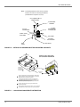
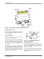
BEARING ALIGNMENT: LB600
Before the supply air blower drive is installed, turn the blower
assembly by hand several times. If it doesn't rotate freely, the
center bearing may have been knocked out of alignment during shipping and/or rigging. To realign, refer to Figure 16 and
the following instructions:
1.
Loosen the bearing collar set screw.
2.
With a drift pin in the bearing collar removal hole, loosen
the bearing collar by tapping the drift pin in the direction
opposite to the shaft rotation.
3.
Loosen bolts "A" and "B".
Unitary Products Group
035-18902-000-A-0402
4.
Remove the shim.
B
NOTE: The bearing support angle must be horizontal to the
unit and below the bearing.
5. Tighten bolts "B" without the shim.
6.
Tighten bolts "A".
7.
With a drift pin in the bearing collar removal hole, tighten
the bearing collar by tapping the drift pin once in the
direction of the shaft rotation.
8.
Tighten the bearing collar set screw.
9.
Loosen bolts "B"
10. Raise the blower shaft and re-install the shim between
the bearing and the bearing support angle.
B
A
E
D
C
C
STATIONARY WEB
11. Tighten bolts "B".
FIGURE 17: DOUBLE GROOVE PULLEY
B E A R IN G C O L L A R
S E T S C R E W
B E A R IN G
B E A R IN G
C O L L A R
B E A
C O L
R E M
H O L
B L O W E R
S H A F T
R IN G
L A R
O V A L
E
If necessary to align pulleys, the housing of the twin groove
motor pulley may extend 25% of its length beyond end of
motor shaft.
Always align twin groove pulleys using the stationary web.
S H A F T
R O T A T IO N
B O L T "B "
B O L T "B "
S H IM
B E A R IN G
S U P P O R T A N G L E
B O L T "A "
FIGURE 16: LB600 CENTER BEARING
AIR SYSTEM ADJUSTMENT
The blower motor pulleys are adjustable by half turns. Select
required RPM from table 5 and adjust pulley.
Check belt tension. Drive packages are supplied with fiberglass belts that must be properly tensioned at installation
because they do not stretch. The belt should deflect 3/16"
per foot of belt span with a 2 or 3-pound force. Alignment of
the resilient motor mount can be corrected by adjustment at
the slots on the end opposite the pulleys.
ELECTRICAL CONNECTIONS
Refer to Figure 30 for Indoor Unit Diagram.
Refer to tables 7-11 to adjust air system.
TWIN BELT DRIVE ADJUSTMENT
Install a power supply to meet the requirements listed in
table 6.
Check to see if both belts drive at the same speed. Do this
by making a mark across both belts. Turn the drive several
revolutions by hand. If mark has not separated, the belts are
traveling at the same speed.
Provide a disconnect switch and fusing as required.
Twin groove blower motor pulleys should be installed with the
shaft set screw (A) towards the motor (see Figure 17).
NOTE: For the 10HP 200/208-volt motors, install the power
wiring to the supply air blower through the starter.
Unitary Products Group
Install interconnecting control wiring between condensing
section, evaporator blower and room thermostat.
17
035-18902-000-A-0402
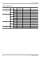
TABLE 6: ELECTRICAL DATA
UNIT MODEL
HP
FLA
VOLTAGE
(3PH-50HZ)
MIN CIRCUIT AMPACITY
MAX. FUSE SIZE (Amps)
15.6
220
19.1
35
9.0
380
11.3
25
23.9
220
29.9
60
14.0
380
17.5
35
15.6
220
19.1
35
9.0
380
11.3
25
23.9
220
29.9
60
14.0
380
17.5
35
29.6
220
37.0
70
17.3
380
21.6
40
23.9
220
29.9
60
14.0
380
17.5
35
29.6
220
37.0
70
17.3
380
21.6
40
29.6
220
37.0
70
17.3
380
21.6
40
5
LA300
7.5
5.0
LB360
7.5
10
7.5
LB480
10
LB600
18
10
Unitary Products Group
035-18902-000-A-0402
TABLE 7: UNIT DRIVE DATA
ADJUSTABLE MOTOR PULLEY
UNIT MODEL
DRIVE KIT
MODEL
NUMBER
BLOWER
RPM
RANGE
1LD0453
1LD0454
1LD0453
FIXED BLOWER PULLEY
BELTS
*
QTY.
PITCH
LENGTH
(IN.)
DESIGNATION
1 3/16
2
60.3
A59
1 3/16
2
60.3
A59
9.0
1 3/16
2
60.3
A59
1 3/8
9.0
1 3/16
2
60.3
A59
1 3/8
9.0
1 3/16
2
56.3
A55
4.7 - 5.7
1 3/8
11.0
1 3/16
2
83.8
B82
765 - 923
5.8 - 7.0
1 3/8
11.0
1 3/16
2
85.8
B84
699 - 831
5.3 - 6.3
1 3/8
11.0
1 3/16
2
76.8
B75
PITCH DIA.
(IN.)
BORE
(IN.)
PITCH DIA.
(IN.)
BORE
(IN.)
644 - 806
4.0 - 5.0
1 1/8
9.0
677 - 838
4.2 - 5.2
1 3/8
9.0
644 - 806
4.0 - 5.0
1 1/8
1LD0454
677 - 838
4.2 - 5.2
1LD0455
854 - 1015
5.3 - 6.3
1LD0456
620 - 752
1LD0457
1LD0458
LA300
LB360
LB480
LB600
*.
Calculated at 1,450 rpm motor speed.
TABLE 8: UNIT BLOWER MOTOR DATA
UNIT MODEL
LA300
LB360
LB480
LB600
HP
MOTOR KIT MODEL
NUMBER
FRAME SIZE
VOLTAGE
(3PH-50-HZ)
5
2LP04605065
184 T
220/380
7.5
2LP04607565
213 T
220/380
5.0
2LP04605065
184 T
220/380
7.5
2LP04607565
213 T
220/380
10
2LP04610065
215 T
220/380
7.5
2LP04607565
213 T
220/380
10
2LP04610065
215 T
220/380
10
2LP04610065
215 T
220/380
15
Field Supplied
Field Supplied
Field Supplied
MAINTENANCE
Filters must be cleaned or replaced as often as necessary to
assure good airflow and filtering action.
To remove filters through the sides of the unit, remove either
the solid side panel on the piping end, or the larger side panel
on the end opposite the piping.
To remove the filters from the front of the unit, loosen 2
screws and raise the top filter retainer. The upper filters can
Unitary Products Group
be lifted over the center filter lip. Three wing nuts are provided under the center filter retainer. Remove these and a
part of the center filter support, giving access to the bottom filters.
Drain pan(s) should be inspected regularly to assure proper
drainage.
The evaporator blower bearings and blower motor bearings
are permanently lubricated.
19
035-18902-000-A-0402
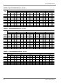
TABLE 9: FAN PEFORMANCE DATA - 25-TON
CFM
RPM
8,000
SP
BHP
9,000
10,000
11,000
12,000
kW
SP
BHP
kW
SP
BHP
kW
SP
BHP
kW
SP
BHP
kW
600
-
-
-
0.30
2.5
2.3
0.20
3.1
2.9
0.02
3.6
3.4
-
-
-
635
0.56
2.4
2.3
0.43
2.7
2.6
0.31
3.3
3.1
0.13
3.8
3.5
-
-
-
700
0.80
3.0
2.8
0.68
3.3
3.1
0.54
3.7
3.5
0.38
4.2
3.9
0.20
4.8
4.5
775
1.12
3.7
3.4
1.00
4.0
3.7
0.85
4.4
4.1
0.70
4.8
4.5
0.54
5.3
5.0
800
1.23
3.9
3.7
1.11
4.3
4.0
0.97
4.7
4.4
0.82
5.1
4.8
0.66
5.6
5.2
875
1.60
4.8
4.5
1.48
5.1
4.8
1.34
5.6
5.2
1.19
6.0
5.7
1.04
6.6
6.2
900
1.73
5.1
4.8
1.61
5.5
5.1
1.47
5.9
5.5
1.33
6.4
6.0
1.17
7.0
6.5
940
1.95
5.6
5.2
1.82
6.0
5.6
1.70
6.5
6.1
-
-
-
-
-
-
TABLE 10: FAN PEFORMANCE DATA - 30-TON
CFM
RPM
10,000
11,000
12,000
13,000
14,000
SP
BHP
kW
SP
BHP
kW
SP
BHP
kW
SP
BHP
kW
SP
BHP
kW
600
0.38
2.8
2.4
0.23
3.3
2.9
0.06
3.9
3.4
-
-
-
-
-
-
635
0.52
3.1
2.7
0.37
3.7
3.2
0.21
4.3
3.7
0.03
4.9
4.2
-
-
-
700
0.77
3.8
3.3
0.64
4.4
3.8
0.49
5.0
4.3
0.33
5.6
4.8
0.17
6.3
5.4
775
1.11
4.7
4.1
0.99
5.3
4.6
0.85
5.9
5.1
0.70
6.5
5.6
0.55
7.2
6.2
800
1.20
4.9
4.2
1.08
5.5
4.8
0.94
6.2
5.4
0.79
6.9
6.0
0.64
7.6
6.6
875
1.54
5.9
5.1
1.42
6.5
5.6
1.29
7.1
6.1
1.16
7.8
6.7
1.03
8.6
7.4
900
1.65
6.2
5.4
1.54
6.8
5.9
1.41
7.4
6.4
1.28
8.1
7.0
1.16
8.9
7.7
970
2.00
7.2
6.2
1.88
7.8
6.7
1.76
8.5
7.3
1.65
9.2
7.9
1.54
10.0
8.6
1000
2.15
7.6
6.6
2.03
8.2
7.1
1.92
8.8
7.6
1.81
9.5
8.2
1.71
10.4
9.0
TABLE 11: FAN PERFORMANCE DATA - 40 TON
CFM
RPM
12,800
14,400
16,000
17,600
19,200
SP
BHP
kW
SP
BHP
kW
SP
BHP
kW
SP
BHP
kW
SP
BHP
600
0.84
6.0
5.2
0.63
7.2
6.2
0.40
8.4
7.2
0.13
9.7
8.4
-
-
-
660
1.19
7.3
6.3
1.00
8.5
7.3
0.78
9.8
8.5
0.50
11.2
9.7
0.19
12.7
11.0
700
1.42
8.2
7.1
1.25
9.4
8.1
1.03
10.7
9.2
0.75
12.2
10.5
0.45
13.7
11.8
760
1.78
9.5
8.2
1.63
10.8
9.3
1.43
12.3
10.6
1.16
13.8
11.9
0.86
15.6
13.5
800
2.02
10.4
9.0
1.89
11.8
10.2
1.69
13.3
11.5
1.43
14.9
12.9
1.14
16.9
14.6
900
2.62
12.8
11.0
2.53
14.5
12.5
2.40
16.0
13.8
-
-
-
-
-
-
930
2.80
13.5
11.6
2.72
15.3
13.2
-
-
-
-
-
-
-
-
-
20
kW
Unitary Products Group
035-18902-000-A-0402
TABLE 12: FAN PERFORMANCE DATA - 50 TON
CFM
RPM
16,000
18,000
20,000
22,000
24,000
SP
BHP
kW
SP
BHP
kW
SP
BHP
kW
SP
BHP
kW
SP
BHP
kW
600
0.82
6.0
5.2
0.59
7.2
6.2
0.35
8.4
7.2
0.08
9.7
8.4
-
-
-
660
1.17
7.3
6.3
0.96
8.5
7.3
0.73
9.8
8.5
0.45
11.2
9.7
0.14
12.7
11.0
700
1.40
8.2
7.1
1.21
9.4
8.1
0.98
10.7
9.2
0.70
12.2
10.5
0.40
13.7
11.8
760
1.76
9.5
8.2
1.59
10.8
9.3
1.38
12.3
10.6
1.11
13.8
11.9
0.81
15.6
13.5
800
2.00
10.4
9.0
1.85
11.8
10.2
1.64
13.3
11.5
1.38
14.9
12.9
1.09
16.9
14.6
900
2.60
12.8
11.0
2.49
14.5
12.5
2.35
16.0
13.8
-
-
-
-
-
-
930
2.78
13.5
11.6
2.68
15.3
13.2
-
-
-
-
-
-
-
-
-
Unitary Products Group
21
035-18902-000-A-0402
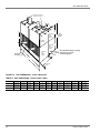
7/8 KNOCKOUTS FOR POWER
AND CONTROL WIRING
AIR
OUT
M
AIR
OUT
K
5/8
5/8
L
K
F
J
D
G
KNOCKOUT
FOR
LIQUID
PIPING
H
C
E
{
LESS
BOTTOM
PANEL
BLOWER
SECTION
AIR
IN
D
KNOCKOUT
FOR
SUCTION
PIPING
AIR
IN
KNOCKOUT
FOR
DRAIN
PIPING
EVAPORATOR
COIL SECTION
A
5/8 PANEL
See detailed drawings for piping
and drain connections
on following pages.
B
D
5/8 BOTTOM
PANEL
FIGURE 18: UNIT DIMENSIONS - LA300, LB360, 480
TABLE 13: UNIT DIMENSIONS - LA300, LB360, LB480
22
MODEL
A
B
C
D
E
F
G
H
J
K
L
M
LA300
100-1/8
95-5/8
33-1/4
36-5/8
74
2-1/2
18-7/8
16-1/2
15-13/16
21-7/8
18
22-9/16
LB360
100-1/8
95-5/8
33-1/4
86-5/8
73-1/4
2-1/2
18-7/8
16-1/2
15-13/16
21-7/8
18
22-9/16
LB480
103-1/8
95-5/8
40-5/8
44
88-5/8
2-1/2
18-7/8
23-7/8
20-11/16
21-7/8
18
22-11/16
Unitary Products Group
035-18902-000-A-0402
FIGURE 19: LA300 PIPING CONNECTIONS
FIGURE 21: LB480 PIPING CONNECTIONS
FIGURE 20: LB360 PIPING CONNECTIONS
Unitary Products Group
23
035-18902-000-A-0402
FIGURE 22: UNIT DIMENSIONS
24
Unitary Products Group
035-18902-000-A-0402
4.7"
13.5"
Liquid
Line
Sys. #1
4.0"
10.1"
Liquid
Line
Sys. #2
3.8"
24.0"
Suction
Line
Sys. #1
3.0"
23.86"
2.1"
6.0"
Condensate
Drain
13.5"
Suction
Line
Sys. #2
3.0"
6.7"
FIGURE 23: LB600 PIPING CONNECTIONS DETAIL
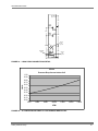
I.W.C.
25-ton
Pressure Drop Across Indoor Coil
1.00
0.90
0.80
0.70
0.60
0.50
0.40
0.30
0.20
0.10
0.00
7000
8000
9000
10000
11000
12000
13000
CFM
FIGURE 24: 25-TON PRESSURE DROP VS. CFM ACROSS INDOOR COIL
Unitary Products Group
25
035-18902-000-A-0402
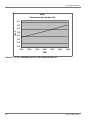
30-ton
Pressure Drop Across Indoor Coil
0.70
0.60
I.W.C.
0.50
0.40
0.30
0.20
0.10
0.00
9000
10000
11000
12000
13000
14000
15000
CFM
FIGURE 25: 30-TON - PRESSURE DROP VS. CFM ACROSS INDOOR COIL
26
Unitary Products Group
035-18902-000-A-0402
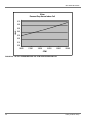
40-ton
Pressure Drop Across Indoor Coil
0.70
0.60
I.W.C.
0.50
0.40
0.30
0.20
0.10
0.00
12000
14000
16000
18000
20000
CFM
FIGURE 26: 40 TON - PRESSURE DROP VS. CFM ACROSS INDOOR COIL (DOMESTIC)
40-ton
Pressure Drop Across Indoor Coil
I.W.C.
1.00
0.90
0.80
0.70
0.60
0.50
0.40
0.30
0.20
0.10
0.00
12000
14000
16000
18000
20000
CFM
FIGURE 27: 40-TON - PRESSURE DROP VS. CFM ACROSS INDOOR COIL (INTERNATIONAL)
Unitary Products Group
27
035-18902-000-A-0402
50-ton
Pressure Drop Across Indoor Coil
0.70
0.60
I.W.C.
0.50
0.40
0.30
0.20
0.10
0.00
15000
17000
19000
21000
23000
25000
CFM
FIGURE 28: 50 TON - PRESSURE DROP VS. CFM ACROSS INDOOR COIL
28
Unitary Products Group
035-18902-000-A-0402
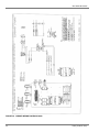
FIGURE 29: INDOOR UNIT WIRING DIAGRAM LB360, 480 & 600
Unitary Products Group
29
035-18902-000-A-0402
FIGURE 30: INDOOR WIRING DIAGRAM LA300
30
Unitary Products Group
035-18902-000-A-0402
Unitary Products Group
31
Subject to change without notice. Printed in U.S.A.
Copyright © by Unitary Products Group 2002. All rights reserved.
Unitary
Products
Group
035-18902-000-A-0402
Supersedes: Nothing
5005
York
Drive
Norman
OK
73069


![Intra-Pod instructions.ppt [Read-Only]](http://vs1.manualzilla.com/store/data/007247390_1-f78b03339eb740c14aa24b2c59786747-150x150.png)