1
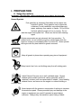
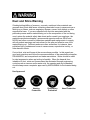
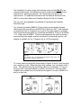
OWNERS
MANUAL
Handheld Drill
MODEL:
HHD323
FORM <<HHD323 rev 10/2009
1
WARRANTY
Norton warrants all products manufactured by it against defects in
workmanship or materials for a period of one (1) year from the date of
shipment to the customer.
The responsibility of Norton under this warranty is limited to
replacement or repair of defective parts at Norton's Stephenville,
Texas factory, or at a point designated by it, of such part as shall
appear to us upon inspection at such point, to have been defective in
material or workmanship, with expense for transportation borne by the
customer.
In no event shall Norton be liable for consequential or incidental
damages arising out of the failure of any product to operate properly.
Integral units such as gasoline engines, electric motors, batteries,
tires, transmissions, etc., are excluded from this warranty and are
subject to the prime manufacturer's warranty.
This warranty is in lieu of all other warranties, expressed or implied,
and all such other warranties are hereby disclaimed.
Important: Before placing equipment in operation, record the following
information.
MODEL:_________ SERIAL NO.___________
PURCHASE FROM: _____________________
ADDRESS: ____________________________
CITY_______ STATE ______ ZIP ________
TELEPHONE NO. ______________________
Before using this equipment, make sure that person using it
read and understand the instructions in this owner’s manual.
2
Table Of Contents
CONTENTS
I. Preparation
A. Safety Precautions
B. Assembly
C. Specifications
D. Electrical Supply
F. Generator
G. Grounding Instructions
H. Electrical Connections
PAGE
4-6
7
7
8-10
8
8
8-10
II. Operation
A. Core Bit Installation
B. Water Supply
C. Drilling Operation
D. Hand Held Drilling Technique
10-11
11
11-12
12-13
III. Component Description
A. Diagram
14
IV. Parts List Section
A. Ordering Information
B. HHD323 Exploded View Parts Drawing
C. HHD323 Parts Listing
15
16
17-18
Read Owners Manual Before Use
Safety Alert Symbol: Information Following This Symbol Is Very
Important.
3
I. PREPARATION
A. Safety Precautions
Important! The following safety precautions must always be observed.
Hazard Symbols
Fuel (gasoline) is extremely flammable and its vapors can
explode if ignited. Store gasoline only in approved
containers, in well-ventilated, unoccupied approved
areas, and away from sparks or flames. Do not fill the
fuel tank while the engine is hot or running. Do not
start the engine near spilled fuel. Never use the fuel as a cleaning
agent.
Engine components can get extremely hot from operation. To
prevent burns, do not touch the engine or related parts while the
engine is running or immediately after it is turned off. Never operate
the engine with any heat shields or guards removed.
Keep all guards in place when operating any piece of equipment
Keep hands, feet, hair, and clothing away from all rotating parts
Lethal Exhaust Gas use only in well ventilated areas. Engine
exhaust gases contain poisonous carbon monoxide, which is
orderless, colorless, and can cause death if inhaled. Avoid inhaling
exhaust fumes, and never run the engine in a closed building or
confined area
Never tamper with the governor components of settings to increase
the maximum speed. Severe personal injury and damage to the
engine or equipment can result if operated at speed above
maximum. Always obey the maximum speed rating of blade.
4
Dust and Silica Warning
Grinding/cutting/drilling of masonry, concrete, metal and other materials can
generate dust, mists and fumes containing chemicals known to cause serious or
fatal injury or illness, such as respiratory disease, cancer, birth defects or other
reproductive harm. If you are unfamiliar with the risks associated with the
particular process and/or material being cut or the composition of the tool being
used, review the material safety data sheet and/or consult your employer, the
material manufacturer/supplier, governmental agencies such as OSHA and
NIOSH and other sources on hazardous materials and make certain to comply
with all product warnings and instructions for the safe and effective use of the
material being cut. California and some other authorities, for instance, have
published lists of substances known to cause cancer, reproductive toxicity, or
other harmful effects.
Control dust, mist and fumes at the source where possible. In this regard use
good work practices and follow the recommendations of the manufacturer/supplier,
OSHA/NIOSH, and occupational and trade associations. Water should be used
for dust suppression when wet cutting is feasible. When the hazards from
inhalation of dust, mists and fumes cannot be eliminated through engineering
controls such as vacuum and/or water mist, the operator and any bystanders
should always wear a respirator approved by NIOSH/MSHA for the material being
cut.
Use Approved:
Eye Protection
Hearing
Protection
Respiratory
Protection
5
Head Protection
1. Know your drilling machine! Read the Owner’s manual carefully. Learn
the operation, application and limitations, as well as the specific potential
hazards peculiar to this equipment.
2. NEVER connect the green [or green & yellow] wire to a live terminal.
3. Use only three-wire grounded extension cords suitable for use outdoors
and of sufficient gage to accommodate power requirements.
4. Replace frayed or damaged extension cords.
5. Keep the work area clean avoiding cluttered work areas.
6. Consider the work area environment!
- Do not expose power tools to rain.
- Wear rubber boots to further insulate yourself from the drill.
- Mop up all excessive water around the work area before and after
drilling.
- Keep the work area well lit.
7. Use extreme caution when drilling through floors. Provide for protection
of all personnel and material below the area. Cores generally drop from
the drill bit at the completion of the hole.
8. Keep visitors away. Do not let visitors contact tool or extension cord. All
visitors should be kept at a safe distance from the work area.
9. Do not force the bit into drilling surface.
10. Dress properly for the work being performed.
- Do not wear loose clothing or jewelry which can get caught in moving or
rotating parts.
11. Don’t abuse the cord. Never carry the tool by the cord or yank the cord to
disconnect the plug from the receptacle.
12. Don’t overreach! Keep proper footing and balance at all times. The
slippery surface created during the drilling operation results in unstable
footing.
13. ALWAYS disconnect the power before servicing or changing accessories
or bits.
14. ALWAYS check, then make sure wrenches are removed from the motor
spindle and bit adapter before connecting power or starting the drill
motor.
15. ALWAYS make sure power switch is in “off” position before connecting
drill to power.
16. Never drill by hand a bit that is over 4” (100 mm) in diameter. Use a drill
stand for bits over 4” (100 mm) in diameter.
You Are Responsible For Your Safety!!!
6
I. PREPARATION
B. Assembly
The HHD323 handheld drill is shipped completely assembled except for core
bit adapters, core bit, and the collar handle. Inspect the drill for shipping
damage. If any damage is found, contact the shipper immediately and file a
freight claim. Saint-Gobain Abrasives, Inc. is not responsible for any freightrelated damages.
Be sure you have the following items:
1. HHD323 handheld drill
2. 27mm Wrench
3. 12” Adjustable wrench
4. 5mm Allen wrench
5. Adapter M18 female to 5/8” male
6. Adapter M18 female to 1-1/4” male
7. Quick Detach Water Hose Adapters
8. Carrying case
Read and understand the remaining sections of this Owner's Manual.
C. Specifications
Dimensions/Weight
Length
Width
Height
Weight
Engine
Engine Type
Volt
Amp
Demand
RPM
Bit Capacity
18.11" (460 mm)
4.33" (110 mm)
9.84" (250 mm)
12.1 lbs
Single Phase
115 v
12 amp
1350 w
0-2200 rpm
1” (25 mm) – 3” (76 mm)
7
D. Electrical Supply
The HHD323 handheld drill is furnished with a 115 volt, single phase motor.
This motor operates within a power range of 110 to 120 volts. Serious damage
can result if the supply line voltage does not fall within this range.
The following wire sizes are recommended when using an extension cord:
Wire Gauge (AWG)
Number 14
Number 12
Number 10
Number 08
Length Of Wire
25 Feet
50 Feet
75 Feet
100 Feet
For Best performance use 50 feet of 10 gauge extension cord. All extension
cords must be one piece, free of any damage (frays, cracks, breaks, burn
marks, exposed wires, and loose ends).
F. Generator:
If a generator must be used, it must be of 4.1kW (4,100 W) or larger. The
generator must have a 15A circuit or greater and capable of providing a
minimum of 4.1kW at the required voltage. Under size generators will cause
motor damage and is not covered under warranty.
G. Grounding Instructions:
Grounding protects the operator from electric shock. At the time of delivery
of the motor is equipped with an approved three-conductor cord and threeprong grounding type plug. The green (green/yellow in CEE-Versions)
conductor in the cord is the grounding wire. NOTE: Never connect the green
(green/yellow) ground conductor (wire) to a live terminal. In case of doubt
concerning the ground of the receptacle, call a qualified electrician and have it
checked for proper ground.
z
z
z
Before connecting the drill to the power source, make sure that the
voltage and cycles shown on the name plate of the motor are the same
as the available electrical power supplied.
Always properly ground the core drill before attempting to start the
motor. The presence of water during the drilling operation requires that
the drill always be properly grounded.
NEVER connect the green (ground) wire to a live terminal!
H. Electrical Connections:
8
The installation of cables, plugs, and switches must be made ONLY by an
authorized electrician. All installations must be made according to the local
regulations for electrical equipment. All components must meet local
requirements. For additional information see the National Electrical Code
(NEC) for the United States and Canadian Electrical Code for Canada.
The use of a 3-prong adapter is prohibited in Canada by the Canadian
Electrical Code.
Fig. A shows a standard NEMA 5-15 plug (male) and receptacle (female),
which should be used with the HHD323 Hand Held Core Drill. If the electrical
receptacle has two (2) conductors as shown in Fig. B an adapter is available
from a local electrical supplier for connecting the NEMA 5-15 plug to an NEMA
1-15. When using a NEMA 1-15 two prong receptacles the green grounding
ear extending from adapter must be connected to a permanent ground. No
adapter is available for Fig. C plugs as this is a 230v receptacle.
NOTE: RECEPTACLE MUST BE GROUNDED FOR SAFE USE OF
ADAPTER:
IF IN DOUBT CALL A QUALIFIED ELECTRICIAN AND HAVE THE
RECEPTACLE CHECKED FOR GROUND
To connect twist lock plugs like those shown in figures D and E, insert the plug
into a matching outlet. When the plug is fully inserted, turn it clockwise until it
locks. This prevents the plug from being pulled out accidentally. To remove
the plug, twist it counterclockwise to unlock it and remove it from the outlet.
Adapters are available from a local electrical suppler to convert a NEMA 5-15
plug to a twist lock.
9
•
For Additional Safety Use A Ground Fault-Interrupter (GFCI ) Device.
•
Do Not Use The Drill In Inflammable, Gaseous, Or Explosive Atmosphere
•
Do Not Expose The Drill Motor To Rain Or Use In Damp Or Wet Locations
•
Do Not Abuse The Cord, Or Carry Or Lift The Motor By The Cord
•
Keep The Power Supply Cord Away From Humidity And Water
•
Make Sure That The ON/OFF Switch Is In The “OFF” Position Before Plugging
Into A Power Supply
•
Unplug The Drill Before Changing A Drill Bit
•
Unplug The Power Cord When Attaching The Water Supply, Also Turn The
Water Valve To The “Off” Position Before Attaching
•
Do Not Use If Parts Of The Motor Housing Are Missing Or Damaged
•
Do Not Use If The Power Cable Or Extension Cable Is Damaged
•
Do Not Make Any Attachments, Adjustments, Or Accessory Changes With The
Unit Plugged In
•
Always Use The Proper Length/AWG For Extension Cords (See The Section
Titled Electrical Supply)
♦ If Water Comes Out Of The Over Flow Bore (Item 3) Stop The Drill Operation
And Replace The Water Ring Seal Immediately
♦ DO NOT Use Or Reuse Waste Water. Dirt And Slurry May Damage The Ring
Seals
•
Prevent Water From Spraying On Any Part Of The Electrical Motor Or Cables
II. OPERATION
A. Core Bit Installation
Adapters are needed to install specific sized core bits.
1. Using a wrench to firmly hold the output shaft, screw the core bit onto the
spindle until snug.
10
2. Placing one wrench on the machined flats of the output shaft and one
wrench on the end adapter of the core bit tighten the bit on the spindle.
Note: Attempting to turn the bit by the barrel rather than by the adapter nut
may break the weld between the adapter nut plate and the barrel.
When using any Hand Held Drill never hand drill a bit larger than 4” (100 mm)
in diameter. Only use a Drill Stand for drill bits larger than 4” (100 mm) in
diameter.
B. Water Supply:
1.
2.
3.
4.
5.
Always disconnect the power supply before attaching or detaching the
water
system to the Clipper HHD323 Hand Held Drill
Attach the Female Quick Coupler to the water supply hose. NOTE: A
pressure tank can only be used for small hole drilling. The pressure tank
should not be lower than 7 PSI (0.5 bar)
Place the Water Valve (Tap) in the “Closed” position
Attach the Female Quick Coupler to the Male Quick Coupler by pulling back
on the Female Quick Coupler retaining ring and pressing it gently into the
Male Quick Coupler.
Turn on the water supply
Slowly turn the Water Tap to the “Open” position
To remove the water supply from the Clipper Hand Held Drill:
1. Slowly turn the Water Tap to the “Closed” position
2. Turn “Off” the water supply
3. Detach the Female Quick Coupler from the Male Quick Coupler by pulling
back on the Female Quick Coupler retaining ring and pulling it gently way
from the Male Quick Coupler.
4. If the job is finished for the day see the section Water System Maintenance
C. Drilling Operation:
The performance of any diamond core bit depends heavily on the use of proper
drilling technique. Although drilling conditions and materials may vary,
following specific guide lines insures faster drilling speeds and longer bit life.
1. Make sure there is no movement in the drill that would cause the core bit to
bind in the hole.
2. Insure that the hole is constantly flushed of abrasive fines by supplying a
sufficient flow of water.
11
3. Slowly guide the bit into the hole so that there is no skidding or movement
of the drill. The entire circumference of the core bit should penetrate the
drilling surface before additional pressure is applied to the handle.
4. Exert steady pressure while drilling. NEVER force the bit into the material!
5. Do not stop the flow of water or rotation of the bit while the core bit is
drilling.
6. Check the core bit if the drilling rate decreases noticeably. The slowing
penetration rate generally indicates that the bit is in need of reconditioning.
D. Hand Held Drilling Technique:
Most drill problems occur due to improper starting, drilling method, and the wrong
power supply and/or extension cord length/AWG. To extend the life of the drill the
following Hand Held drilling operation instructions must be followed. Not following
these instructions will damage the tool and void the warranty!!!
Keep The Drill Perpendicular To The Work At All Times.
Do Not Force The Drill
12
1. Start The Drill At 45° To The Work Surface With
The Bit About 1/2” From The Work Surface. The
Drill Must Be Running At Full Speed Before The
Bit Comes In Contact With The Work Piece
2. Slowly Lower The Bit Into The Work Piece Until
The Drill Bit Has Cut About 1/4” In To The Wok
Piece
3. Slowly Bring The Drill Perpendicular To The
Work Piece (Slide Friction Due To Drilling At An
Angle Will Cause The HD Hand Held Drill Unit To
Vibrate And Possibly Shut The Drill Unit Off)
Let The Drill Do All Of The Work DO NOT
FORCE THE DRILL INTO THE WORK
PIECE!!!!
4. Remove The Core From The Hole About Every
2” To 3”
Do Not Stop The Drill Until It Is Out Of The Hole
5. When Restarting The Hand Held Drill Bring The
Drill Up To Full Speed With The Bit About 1/2”
From The Bottom Of The Hole And
Perpendicular With The Hole. Slowly Lower The
Drill Unit It Comes In Contact With The Work
Piece
Repeat Steps 4 and 5 Until The Job Is Completed
13
If Steel Is To Be Drilled Use The Lowest Speed And Reduce Feed Pressure
When drilling by hand use a drill bit that is has a bond that is one (1) class softer
than you would normally use with a Rig Mounted drill.
III. COMPONENT DESCRIPTION
A. Diagram
14
IV. PARTS LIST SECTION
A. Ordering Information
1. List model number and serial number of machine.
2. List part number and serial number of part not the item number.
3. Wherever alternate parts are shown due to product improvement, inspect
the part you have and provide additional description as necessary.
4. Specify mode of shipping desired, such as, parcel post, truck, U.P.S., best
way, etc.
For the nearest Clipper distributor call 1-800-554-8003
NOTE: All parts are sold as individual (each) unless noted otherwise
15
B. HHD323 Explode View Parts Drawing
16
2
3
4
61
27
28
62-1
1
16-1
5
29
6
30
62
7
8 9
31
58
10
16-1
11
36
12
13
59
35
51-1
34
14
53
54
55
52
32
15
51
38
16
27
17
18
37
57
33
19
56
50
20
39
21
40
22
41
49
46
48
23
60
47
26
24
42
27
25
45
44
43
C. HHD323 Parts Listing
Item
1
2
3
4
5
6
7
8
9
10
11
12
13
14
15
16
16-1
17
18
19
20
21
22
23
24
25
26
27
28
29
30
31
32
33
34
35
36
37
DESCRIPTION
GEAR CASE HHD323
SPINDLE HHD323
OIL SEAL 32D 22d DOUBLE LIP SEAL (7SS)
HANDLE COLLAR HHD323
HANDLE AND ATTACHMENT BAR HHD323
BEARING RADIAL 6003LLU D35 d17
BEARING RADIAL 6003ZZ D35 d17
INTERNAL C-CLIP M35
EXTERNAL C-CLIP M17
EXTERNAL C-CLIP M9
PLATE HHD323
PLATE FRICTION HHD323
METAL COLLAR HHD323
GEAR FIRST HHD323
WASHER CONICAL D28 d12.2
NUT SLOTTED
BEARING RADIAL 608ZZ D22 d8 (CM)
BEARING RADIAL 608ZZ D22 d8 (C2)
PIN M5X15 DOWEL
DIAPHRAGM HHD323
BAFFLE HHD323
O-RING 24x2mm DIN3771 NBR872 207254
BEARING RADIAL 609ZZ (C3)
ARMATURE HHD323
BEARING RADIAL 608ZZ (C3)
WASHER M15 WAVE
MAGNETIC FIELD HHD323
SCR 3/16"-12 X 2-1/2" SELF TAPPING PHILLIPS
HEAD
WASHER M5 LOCK DIN127B
WASHER M5 DIN125 FLAT
PINION BUSHING SECOND HHD323
KEY 3Xx16mm
GEAR SECOND HHD323
MOTOR HOUSING HHD323
SCR M5 X 10 0.8 DIN916 CUP POINT SET
BRUSH HOLDER HHD323
BRUSH (2) HHD323
BRUSH CAP (2) HHD323
SCR M5 X 10 0.8 DIN912 SHCS
17
Qty
1
1
2
1
1
1
1
1
1
1
2
2
1
1
2
1
1
2
1
1
1
1
1
1
1
1
1
2
Part No
244004
244005
244006
244001
244000
244007
244008
244009
244010
244011
244012
244013
244014
244015
244016
244017
244018
244019
244020
244021
244022
207254
244023
244024
244025
244026
244027
244028
2
2
1
1
1
1
2
2
2
2
4
502088
235065
244030
244031
244032
244033
241027
244034
244035
244035
244036
C. HHD323 Parts Listing
Item
38
39
40
41
42
43
44
45
46
47
48
49
50
51
51-1
52
53
54
55
56
57
58
59
60
61
61-1
62
Optional
Optional
Optional
Optional
Optional
Optional
DESCRIPTION
WASHER M5 DIN125 FLAT
ARM BASE TELESCOPIC HHD323
SCR 5/32”-16 X 5/8" SELF TAPPING PHILLIPS HEAD
RUBBER COVER HHD323
ARM TELESCOPIC HHD323
RUBBER SHOULDER PAD HHD323
SCR M3.5 X10 SELF TAP PHILLIPS DIN7981
SPRING SHOULDER STOCK HHD323
LOCK RELEASE LEVER HHD323
SCR M6 X 35 1.0 DIN912 SHCS
NUT M6 1.0 DIN934 HEX
SCR M6 x 25 1.0 DIN933 HHC
HAND GRIP HHD323
SWITCH POWER HHD323
WIRE SWITCH HHD323
CIRCUIT BREAKER 9A HHD323
WASHER THERMAL PROTECTOR HHD323
CABLE CLAMP PLATE THERMAL PROTECTOR
HHD323
SCR 5/32"-16 X 1/2" SELF TAPPING PHILLIPS HEAD
SCR 5/32"-16 X 1-1/2" SELF TAPPING PHILLIPS
HEAD
SCR 5/32"-16 X 3/4" SELF TAPPING PHILLIPS HEAD
WIRE GROUND HHD323
WIRE HHD323
POWER CABLE MAIN HHD323
PLUG
SCR M5 X 25 0.8 DIN912 SHCS
WATER HOSE ASSEMBLY HHD323
WRENCH 27mm OPEN END
WRENCH ADJUSTIBLE 12"
WRENCH 5mm HEX KEY (ALLEN)
ADAPTER M18 TO 5/8"-11 MALE
ADAPTER M18 TO 1-1/4"-7 MALE
CASE CARRYING HHD323
18
Qty
4
1
4
1
1
1
1
1
1
1
2
1
1
1
1
1
1
1
Part No
235065
244037
244038
244039
244040
244041
244042
244043
244044
244045
300833
300867
244003
244002
244046
244047
244048
244049
2
4
244050
244051
2
1
1
1
1
1
1
1
1
1
1
1
1
244052
244053
244054
244055
244056
244057
244058
244059
244060
244061
244062
244063
232176
NOTES:
Saint-Gobain Abrasives
2770 West Washington
Stephenville, TX 76401
Phone: 800-554-8003
Fax: 800-443-1092