1
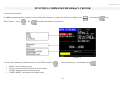
DM14B/C DIGIMAX
USER GUIDE and
MENU NAVIGATION
COMBINED DIGITAL & ANALOG
PROFESSIONAL ANALYZERS FOR:
RADIO, TV, CATV & SATELLITE
4-2250 MHz QPSK-COFDM-QAM-MPEG
Subject to change without notice
DM-14B & DM-14C User’s Guide
Code: UG-DM14B-14C
Title: DM14B & DM14C User’s Guide
Edition: 1.16/2.0-EN/1.00
Draft Version
2
DM-14B & DM-14C User’s Guide
INDEX
Useful Suggestions ........................................................................................................................... 5
Satellite Dish pointing (Sat Point Function) ...................................................................................... 11
Configuration Menu ........................................................................................................................ 13
Special functions menu & video test pattern Generator ....................................................................... 14
Program Store Menu (Memory) ........................................................................................................ 15
Program Store Sat Menu (memory) Examples..................................................................................... 16
Program Store Radio Menu (memory) Examples ................................................................................. 16
Program Store TV Menu (memory) Examples ..................................................................................... 17
Analogic TV Measurement............................................................................................................... 18
Funzione Video Lines ..................................................................................................................... 19
Funzione H-Sync for DM-14B .......................................................................................................... 20
S/N Measurement for DM-14C… Being Prepared ............................................................................... 21
Demodulated COFDM Digital TV measurements ................................................................................ 22
Demodulated COFDM Digital TV measurement COSTELLATION........................................................ 23
Demodulated COFDM Digital TV Measurements: SERVICES .............................................................. 24
COFDM parameters automatic search help function ............................................................................ 25
Emulated COFDM Digital Tv Measurement ....................................................................................... 26
Demodulated QAM Digital TV measurement ...................................................................................... 27
Demodulated QAM digital TV measurements CONSTELLATION......................................................... 28
Demodulated QAM Digital TV Measurement Services ........................................................................ 28
QAM Parameters Automatic Search Help Function ............................................................................. 30
Emulated QAM Digital TV Measurement .......................................................................................... 31
Misura TV Digitale 8VSB Demodulata .............................................................................................. 32
Demodulated 8VSB Digital TV Measurement Constellation ................................................................. 33
Demodulated 8VSB Digital TV Measurement Services ........................................................................ 34
Help Function & Automatic Search for 8VSB parameters .................................................................... 35
FM Radio Measurement ................................................................................................................... 36
DAB Measurement .......................................................................................................................... 37
Analogic Sat Measurement .............................................................................................................. 37
Demodulated Digital Sat QPSK Measurement .................................................................................... 38
Demodulated Digital Sat QPSK SERVICES ....................................................................................... 39
QPSK Parameter AUtomatic Search Help Function ............................................................................. 41
Analog TV Spectrum ....................................................................................................................... 42
COFDM-QAM-8VSB Spectrum ........................................................................................................ 43
FM Radio Spectrum ........................................................................................................................ 44
DAB Spectrum ............................................................................................................................... 45
Analog Sat Spectrum....................................................................................................................... 46
QPSK Spectrum .............................................................................................................................. 47
V.SAT Spectrum Mode .................................................................................................................... 48
Sat Point Spectrum Mode ................................................................................................................ 49
Δ MRK SPECTRUM MODE ............................................................................................................. 50
Δ MRK-C/N SPECTRUM MODE....................................................................................................... 51
MKR BW Spectrum Mode ................................................................................................................ 52
SPECTRUM FUNCTION MRK BW PWR ............................................................................................ 53
Live & Recall Spectrum Function ..................................................................................................... 54
Scroll Menu Function ...................................................................................................................... 54
Special TV Bars Scan Function ........................................................................................................ 56
Special RPL Spectrum Function ....................................................................................................... 57
Sat Finder… Being Prepared ............................................................................................................ 58
Special Reflectometer Bridge Function (to measure short circuit or interruption in coax cables ............... 58
Function: Commans For DiSEqC 1.2 Rotor ........................................................................................ 61
DESCRIPTION OF THE VARIOUS FUNCTIONS .............................................................................. 62
Fast & Advanced Autoscan Function (Automatic TV Search) ............................................................... 63
DATA LOGGER Measurement SAVE ............................................................................................... 65
Data Logger ‘‘Measurement’’: RECALL ............................................................................................ 66
3
DM-14B & DM-14C User’s Guide
FILE
FILE
FILE
FILE
FILE
FILE
Manager
Manager
Manager
Manager
Manager
Manager
FILE ........................................................................................................................ 67
INFO ....................................................................................................................... 68
SHOW ..................................................................................................................... 69
RENAME ................................................................................................................. 70
DELETE .................................................................................................................. 71
DEFRAG .................................................................................................................. 72
APPENDICES
A1 – Technical Specifications .................................................................................................. ........ 73
A2 - SMART Program ..................................................................................................................... 80
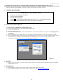
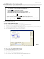
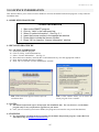
1.0 How to connect your measuring instrument to a PC ............................................................................. 81
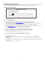
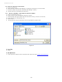
2.0 Firmware Upgrades ................................................................................................................... 82
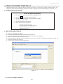
3.0 Get Screen................................................................................................................................ 84
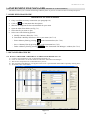
4.0 Instrument File Manager (Data Logger Transfer) .......................................................................... 85
5.0 Instrument File Manager ............................................................................................................ 87
6.0 How To insert User Data ............................................................................................................ 89
7.0 Instruments File Manager (Memory Plan Management) .................................................................. 91
8.0 Instrument File Manager (Standard Channel Plan Management ....................................................... 93
9.0 Licence Information .................................................................................................................. 95
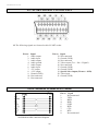
A3 – Scart Socket Connection .......................................................................................................... 96
A4 - Null Modem interface Cable ..................................................................................................... 96
A5 – Trouble Shooting .................................................................................................................... 97
A6 - Lead Battery Maintenance and Recharge .................................................................................... 98
A7 - Accessories ............................................................................................................................ 99
NOTES .......................................................................................................................................... 99
A8 - Front & Side Panel Descriptions ............................................................................................ . 101
A9 - How to Use the Bag’s front Panel Protection flap in Digimax Instrumets ..................................... 103
A10 - Service Notes and Guarantee Regulations ............................................................................... 104
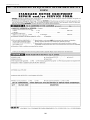
A11 - Fault Identification Form ..................................................................................................... 105
A12 - Standard Rover equipment repair and/or Service Form ............................................................. 106
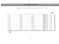
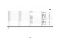
A13 - Memory Plan Table .............................................................................................................. 107
NOTES ........................................................................................................................................ 111
4
DM-14B & DM-14C User’s Guide
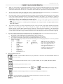
USEFUL SUGGESTIONS
1)
Thank you for choosing our measuring equipment, which is currently used and appreciated by the most important
Satellite Service Providers, Broadcasters and by many installers, because it is user friendly and provides complete
and accurate measurements. On our part, we will do our best to fulfil your requirements now and in the future.
2)
This is a new concept, quick user guide that is easy to consult. Select the function/measurement you need directly
from the index and on the respective page you will find all the relative menus.
3)
First of all please do not be concerned about the large quantity of menus found on the following pages; as this meter
is the most complete and advanced TV & SAT analyser available on the market, it is clear that it is capable of
carrying out many measurements. If you take a closer look you will notice that the menus are similar and basically
divided into two groups: MEASUREMENTS and SPECTRUM.
• MEASURE: analogue TV, COFDM, QAM & 8VSB digital TV, analogue Sat & QPSK digital Sat, Radio FM and
DAB.
• SPECTRUM: analogue TV, COFDM, QAM & 8VSB digital TV, analogue Satellite and digital QPSK satellite,
Radio FM and DAB.
4)
You will also see from a very early stage that all you have to do is store the various plans (PLAN) and programs
(PRG) (or ask your supplier to do it for you using the PC program, opt. SMART PRO), then choose the plan
(PLAN) and the program (PRG) needed each time. Select the spectrum function (SPECT) or the measurement
function (MEAS) and the meter will do everything automatically. Isn’t that great? We also suggest you photocopy,
cut–out and fill-in the tables on pages 108/109 and insert them in the transparent pocket in the instrument’s bag flap.
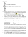
5)
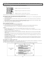
Important: The instrument leaves the manufacturer with some default settings for test and demonstration purposes:
a) The instrument turns off after 5 minutes' inactivity, for transport by air.
This setting can be modified from the CONFIGuration menu (see page 12).
b) Check that you are using a meter with the correct channel plans for your country.
It is possible to modify this setting from the CONFIGuration menu (see page 12).
c) Some plans have been previously stored in the meter using one or more programmes in the various operation
modes, for example:
PLAN
MODE
PLAN
MODE
N.B. These are only examples to
1
ANALOG TV
80
Mixed for
help you use and understand your
2
FM RADIO
81
factory tests
meter. We suggest you store a
3
QAM
mixed plan for every town or for
4
COFDM
every type of installation or
5
ANALOG SAT
modulation. Important: Do not
6
QPSK
cancel these channel plans.
7
DAB-PLAN
8
ASTRA 19,2 E
9
EUTELSAT 13°° E
6)
The most important keys are:
ON/OFF switch and Reset button (keep it pressed for 10 seconds to activate the RESET function if
the meter stalls).
For measurement mode selection, (AN. TV, QAM, COFDM, AN. SAT, QPSK, FM RADIO, DAB)
For memory plan selection from 1 to 99.
For stored prog selection from 1 to 199,
chan,
LNB & DiSEqC power supply, freq.
Frequency selection (keep pressed for 2 seconds to activate RPL spectrum function)
To select MEASURE or SPECTRUM mode and ESCAPE, to quit the various menus
and go directly to measurement mode
5
DM-14B & DM-14C User’s Guide
To select PLAN–PRG–CHAN–FREQ decrease, etc
To select PLAN–PRG–CHAN–FREQ increase, etc.
To activate, confirm and/or quit the various menus, measurements or settings
(keep pressed for 2” to activate the numerical keyboard and the scroll menu)
Activates, in cycles, the various measurement levels.
Activates/disactivates the various menus related to the activated function.
N.B. Dual function keys: when you see the words 2" or 10” (2 or 10 seconds) written above the keys, you should keep
the key pressed for 2 or 10 seconds to activate the second function.
All the remaining keys are just as easy to use and you can find complete descriptions on the last page (folded) of this
guide: we suggest you open it out for easier use.
key pressed for 2 seconds,
To use the numerical keyboard (SHIFT function), keep the
digit the number of the plan, channel, program, frequency etc. and press
again to confirm.
If you prefer, you can adjust/select all the various parameters by rotating the encoder knob.
7)
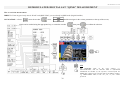
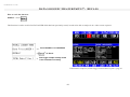
We promised you a user–friendly instrument, capable of doing everything by itself (or nearly); as you can see when
you are in measurement mode (MEAS) the upper part of the screen shows all the settings, for example: MODE–
PLAN–PRG–CHAN– FREQ–LNB– DiSEqC, etc. whereas the lower part of the screen shows all the measurements.
These can be seen individually or all together, by pressing the MORE MEAS key once according to the
measurement level you require (you can program levels 1–2–3 in CONFIG. See p. 12)
8)
If when navigating within the measurements you change any parameters, the program number will disappear.
Simply press PRG and reselect the previous program number by pressing the arrow keys to recall the previous
parameters, or if you want, press MEMORY to store the configuration you are using (see page 14).
9)
Now, please read the index on page 3, then carefully study the three most important menus to start:
• CONFIGURATION MENU
Page 12
• SPECIAL FUNCTION MENU
Page 13
• PROGRAM STORE MENU
Pages 14-15-16
You will learn the remaining functions in a few days by using the instrument. The first time you use the meter, we
strongly advise you connect it to a satellite dish or antenna which has already been installed and is operational and
where you know the channels and frequencies well.
10)
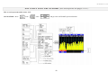
As you can see, in MEASUREMENT mode, the top left hand side of the display shows in which function you are
positioned, for example: QPSK. The upper part of the screen shows all the meter's settings (MODE), for example:
PROG–CHAN–FREQ etc., which can be directly recalled using the respective, direct function keys. The lower part
of the screen shows the POWER/LEVEL measurement and if you press the key MORE MEAS key once or twice
you can recall all the other measurements, which can be carried out. By pressing SPECTRUM, the meter instantly
shows, in the lower left-hand side of the screen, the mode you are in. (Remember that the spectrum can be automatic
or manual, see relative MENU).
11)
You can navigate in every screen using the UP and DOWN keys and in measurement mode using the direct function
keys. Please remember that this type of navigation is the same for all of your meter's menus and screens and that
when you are in digital mode, the response of the various menus becomes a little slower.
12)
Now go to the CONFIGURATION MENU, keep the SPECIAL key pressed for two seconds (see page 10). Select
your country's standard, the measurement unit you prefer and the TIMER setting (if you set "5 min" the meter turns
off after 5 minutes of inactivity and re-starts from the last measurement without losing data). You can adjust the
6
DM-14B & DM-14C User’s Guide
volume of the keys’ beep sound. To exit CONFIG. MENU press ESCAPE/MEAS. Please avoid using the
cancellation menu of the memory banks until you are confident with the use of the meter.
13)
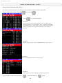
Now let us take a look at the SPECIAL MENU (see page 13). To reach this menu, press the SPECIAL key once:
• SELF TEST: this is used if there are faults to see which parts are not communicating and to obtain the various
data information needed to inform the ROVER service (including the SW and FW versions and the instrument’s
serial number SN).
• A/V MONITOR: forces the video/audio input from the Scart socket (even without 12 V on the relevant PIN).
• TEST MONITOR: generates a test pattern (which can be used to test TV DC installations).
The video is available on pin 15 of the SCART socket.
• RF/IF INPUT SEL: selects the meter’s RF IN, either RF or IF: (38.0 / 38.9 / 45.75 MHz)
• VOLTMETER: measures the AC/DC voltage present at the RF connector.
• REFLECTOMETER: to measure the distance of a short circuit, interruption or mismatching in coaxial cables.
• AUTO SCAN (TV): to scan a channel plan for the search of analog or digital (COFDM) TV channels and
the relative automatic memorization inside the plan.
• FILE MANAGER: for file management (canalizations, plans, loggers, etc…) in the memory.
14)
BARS SCAN FUNCTION: This activates the bar chart graphics representation. In a display it is possible to see the
level/power of all the TV programmes stored in a plan. This function is useful for tilt adjustments and equalizations
in cable distribution networks and headends.
15)
NAVIGATION IN MEASUREMENT MODE (from pages 17 to 35) the various parameters can be quickly
changed using the direct function keys. We remind you once again that in this case the program number disappears.
At this point you have two options:
a) Press the programme key and select the same or another program number.
b) Press MEMORY and store the selected parameters previously modified (see page 14).
16)
NAVIGATION IN SPECTRUM MODE (from pages 36 to 47): the various parameters can be navigated using the
arrow and ENTER keys and are the same as those used by other more expensive, professional spectrum analysers.
The measurement dynamic range and the spectrum speed of this instrument are by far the best in this category and
despite everything, AUTOMATIC mode is very easy to use. Let’s take a look at some of the main functions:
• Reference level: this is the level of the reference line (the first line at the top of the grid) is adjusted
automatically to the carrier with the highest level inside the SPAN. When the SPAN varies, press SPECTRUM
twice to up-date and obviously you can also manually adjust it using the UP & DOWN keys. (N.B. The ref.
level corresponds to the attenuator of previous instruments). Remember that each time you change mode or turn
on the instrument again the ref. level automatically returns to the top of the ref. level (also in manual mode).
• Marker Frequency: shows the marker frequency (vertical dotted line); automatically in digital and analogue
SAT and it always positions in the centre of the carrier, whereas in analogue TV it always positions on the video
carrier. N.B.: The FREQUENCY MARKER is basically the meter's frequency tuning; in fact the marker can be
moved on the various carriers and when you go to MEAS mode you are automatically positioned on the same
frequency. If this frequency is exactly the same as one of the memorised channels, you will also see the relevant
channel, otherwise the display shows 3 lines (to remind you that something has been changed). Important: the
cursor also navigates outside the SPAN's limits, to the far left (start), to the far right (stop). If you release the
arrow keys every now and then, the tuned carriers are shown (the ones that were previously out of the SPAN
range). Naturally if you change from SPECT to MEAS, you can go directly to the tuned carrier/channel. For
easier viewing in Analogue TV and with 10 MHz SPAN, the centre of the channel will be positioned in the
centre of the display, whereas with the rest of the SPAN the marker is positioned in the display's centre.
• Marker level: shows the level of the signal measured by the marker (horizontal dotted line with crosses) and is
connected to the marker frequency position.
(N.B. When the MRK level line is on the highest carrier, it may be confused with the REF LEVEL line, the
highest line on the grid and become invisible).
• SPAN: this always shows the total bandwidth in MHz between the extreme left and extreme right of the display
(if you divide the value by 10 you can obtain the value of each square division).
• dB/div: shows the value in dB between each division of the horizontal grid. This is very helpful if you require a
wide dynamic range, e.g. 10 dB/div., to see noise AND interferences or a high resolution, 1 dB/div. For very
accurate SAT dish pointing both in SAT & TV. In this condition you can easily appreciate variations in dB
decimals.
• MODE: it shows which mode the instrument is working in (the various digital or analogue modulations, TV or
SAT etc.) and in SAT, you can also select the satellite dish pointing function; it automatically sets the spectrum
to easily point any satellite dish. To quit this function press ESCAPE/MEAS. MODE can also be used to select
the V.SAT function, providing a high resolution spectrum for V.SAT and SCPC installations.
May we remind you that when you press MENU you can also select:
• SPECTRUM: automatic or manual. If positioned on AUTOMATIC it always adjusts the SPAN and the dB/
so you can see the carrier, which is being examined.
• DEFINITION: high, medium, low. This increases the spectrum speed (to facilitate dish pointing).
7
DM-14B & DM-14C User’s Guide
•
•
•
•
•
•
•
17)
PICTURE: spectrum with outlines only or full white
∆ MARKER: freq./level difference between two signals and C/N measurement
MARKER BW: to adjust filters, amplifiers, etc. and to measure digital power in SPECT mode “BW–PWR”.
MAX HOLD: peak memory. Maintains the max. peak reached during a series of measurements
DC at RF in: output power supply (5, 12, 15, 18, 24 V – OFF).
LNB L.O.: local oscillator.
BUZZER: ON/OFF activates an acoustic sound which varies with the signal level or digital satellite quality.
EMULATED COFDM/QAM DIGITAL TV MEASUREMENTS (DEMODULATED MEASUREMENTS:
COFDM supplied, QAM optional): These allow you to carry out perfect average power and C/N measurements,
provide a BER evaluation and the quality of the signal (FAIL–MARGINAL– PASS).
HOW THE EMULATED DIGITAL MEASUREMENT WORKS: The signal is measured in RF based on the
C/N measurement and multiplex flatness. Thanks to a series of special algorithms, defined and registered by
ROVER in co–operation with some UK DTG (Digital Terrestrial Group) engineers in 1998 and later optimised, it is
possible to provide a good signal evaluation in both cases of adjacent and non–adjacent channels (selectable n/f –
near/far) without demodulating the digital signal. The measurement accuracy is very high, except in rare cases of
interference completely hidden under the digital multiplex spectrum.
18) LNB-POL & DiSEqC: as you have already seen, there are two different settings, which make the instrument the
most complete and easiest to use in the world:
• LNB: OFF, VERT HIGH, VERT LOW, HORIZ HIGH and HORIZ LOW Polarization
• DiSEqC: off–a–b–c–d, the combination of these two parameters enables you to select the various multi-switches
with 4 cables “a”, 8 cables “b”, 12 cables “c”, 16 cables “d”.
19) You can obtain other very interesting spectrum functions with your instrument if you connect it to an optional noise
generator, for example the “CNG–80” or “CNG–70”:
• Scalar network analyser (wobulator), in “MRK BW” spectrum function, for the calibration and test of channel
filters, amplifiers, splitters, traps, outlets, coaxial cables and relevant VSWR or R.L. measurement of standing
waves ratio (with a reflect meter bridge).
• Coaxial cable reflect meter (“∆ MRK” spectrum function) to measure the distance of a short circuit or
interruption in coaxial cables (using a "T" connector and slide rule).
20) RESET: if the meter stalls and you are unable to turn it off, keep the ON key pressed for 10 secs and the instrument
will immediately restart. If you find that the instrument always blocks in the same situation, please contact the
manufacturer and you will be given, as an award, a year's service free of charge in addition to the standard one.
21) SOFTWARE UP–GRADE: As you well know, another excellent function of this meter is the possibility of up–
grading software free–of–charge via internet. To carry out this operation, consult Rover Instruments web site
(www.roverinstruments.com) and/or contact the service in your country.
22) START–UP MENU: this appears for two seconds every time you turn on your instrument and contains all the
information necessary for the service technicians in the case of repairs or software up-grades via internet (you can
find the same data in the SPECIAL, SELF TEST Menu).
23) We suggest turning off the meter when connecting or disconnecting the RS232 interface.
24) It is possible to store separate or mixed multi–standard plans (e.g. France/Europe or China/Hong Kong) according to
your requirements.
25) The instrument is supplied with interchangeable input connectors “F”, “BNC”, “IEC” or “N”.
26) If the TV signals are weak, or have lots of interference, and you have difficulty in tuning the TV pictures, exclude the
OSD and reactivate it, this operation should help you to tune TV pictures.
27) If the words on the screen do not tune during the frequency tuning of analogue TV and SAT programmes, briefly
remove the signal from the RF input and the words should stabilize.
28) If the instrument loses the vertical sync., with TV and SAT analogue pictures, press MENU and check that it is set to
the correct standard: 50 Hz PAL-SECAM and 60 Hz NTSC.
29) To eliminate the MENU words, press the MENU key.
30) Linear bar chart for level/power with memory & digital quality, e.g. QPSK, these are available in MEAS level 2.
8
DM-14B & DM-14C User’s Guide
N.B. With reference to fig. 8, the NETWORK name you can read in the centre to the right, e.g. NETNAME=SKY, is the
NET.ID table transmitted via satellite by the operator and which the instrument reads by extracting the information
from the MPEG data. However, the prog. name, read in the centre to the left under the word MENU, e.g. PROG
NAME: SKY1, is the one you, or your dealer, has pre-stored and can be varied only using a PC, opt. (see page 19).
N.B. When you activate MORE MEAS 3 (where available) and MENU, due to problems with space, the quality bar chart
and the level/power bar chart both respectively disappear. The white arrow, near to the quality bar chart, indicates
the minimum quality required to achieve a PASS in automatic tests.
32)
C/N MEASUREMENT
In some cases the C/N measurement of analog signals may vary with the level because when the level increases
some RF attenuators could be inserted. The automatic insertion of attenuators reduces the instrument’s sensitivity
and consequently reduces the C/N read on the screen, which will be less than the real one. To avoid this carry out
the following procedure:
• Select normal spectrum mode (without activating the C/N measurement)
• Fix the span at 200 MHz when in AN-SAT (analog satellite)
• Fix the span at 10 MHz (or 20 MHz) when in AN-TV (analog TV)
• Increase the REF-LEVEL (reference level) using the UP key, in 1 dB steps, until you see the noise lower by
approximately 10 dB
• If the noise goes under the line at the bottom of the screen, change the spectrum scale and set it at 10 dB/DIV (this
may occur in analog sat mode)
• Press MENU and select the ΔMRK (delta marker) activate the C/N select.
WARNING: make sure you do not press MEAS or any other key, because the attenuators will set using
standard values.
• Using the UP and DOWN keys bring the marker to the point where you want to measure the noise and read the
C/N value (which will correspond to the measurement filter bandwidth), in the window in the lower part of the
screen (ΔMRK C/N),
• May we remind you that when you measure the C/N in analog TV or SAT mode with the _MRK (without
specifying the C/N), the band correlation is not carried out automatically. In this case you should subtract 10 dB
from the measurement value if you are carrying our a satellite measurement, and 16 dB from the value for TV
measurements.
33)
C/N Measurements in emulated COFDM demodulation mode.
We suggest following these rules when carrying out emulated C/N measurements:
• Use C/N far when there are adjacent channels
• Always use C/N NEAR when there aren’t any adjacent channels
• If you are carrying out measurements on a head-end with selective filters and channel converters, only use the C/N
near measurement. In this case the C/N far measurement could measure a higher C/N than the real value.
To fix a C/N far or C/N near measurement, activate the configuration menu (see page 10 which contains the
configuration menu description).
9
DM-14B & DM-14C User’s Guide
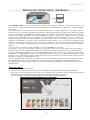
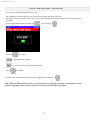
DM-14B & DM-14Color Digimax
The DM-14B and DM-14Color meters allow you to visualise digital pictures of non-encrypted services (FREE-TO-AIR),
contained in the digital signals received at the RF input of the meter, in other words:
- Digital transponder transmitted via satellite with QPSK encryption,
- Digital multiplex transmitted via ether with COFDM encryption,
- Digital multiplex transimitted via cable with QAM encryption.
There are many services (TV or Radio programmes) inside a digital signal, such as the ones listed above. The
MPEG board allows you to see/listen to any of these services as long as they are not encrypted. To select one of
these services and obtain both the picture and the data of the Audio and Video PID, please refer to the
description of the “SERVICES” option in the MENU described on pages 22-27 and 34 of the manual.
It is important to note that when a digital signal is tuned and you want to see the picture of one of the services,
you should select a service using the “SERVICES” menu (see pages 22-27 or 34). Whenever a digital signal is
stored in a program in a memory plan, the visualization of the picture regarding a service contained within it
occurs only if this service was selected using the “SERVICES” menu. Consequently it is important to note that
every time you recall a digital program contained in any memory plan, the picture shown will be the one
belonging to the last selected service available for that transponder (see pages 22-27 and 34). If this selection is
not used, the board will not show any picture.
Example of a picture and relative data from the indicated transponder, obtained using the
“SERVICES” selection contained in the menu associated with digital signals.
10
DM-14B & DM-14C User’s Guide
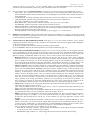
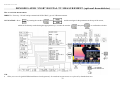
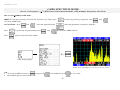
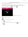
SATELLITE DISH POINTING (SAT POINT function)
As this is a function which is used often and is, at the same time, facilitated by our automated high-resolution spectrum, we
thought we would dedicate a chapter to this subject (please also refer to the “QPSK” SPECTRUM).
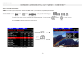
a)
Activate SAT mode, analog or QPSK
(whichever you prefer).
or simply select a SAT programme, preferably in centre band, already pre–stored to receive the satellite and relative
band and polarization you require (e.g. Hot bird 13° E, VE l HI ↑, 11842,0 MHz).
b)
Press SPECTRUM.
c)
Press ENTER
(to quit MRK FREQ)
d)
Press the
key twice to go to MODE.
e)
Press
f)
Connect the LNB assembled on the dish to the RF IN of your meter.
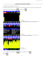
g)
At this point the SAT POINT function has already automatically set the best SAT spectrum vision for you to carry out
satellite dish pointing, without having to touch your meter again (see fig.1).
, and press
once or twice to go to
Fig.1 LNB noise, without carriers
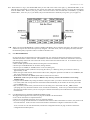
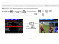
h)
Start pointing your dish (whose elevation has already been adjusted) in the correct direction until you can see some
carriers appear out of the noise and maximise them as shown in the two examples below (fig. 2 and 3). In theory the
satellite dish pointing is now complete; later we will see how to make it perfect and/or simplify the procedure using
some of the instruments special functions.
Fig.2 The carriers start to appear from the noise
Fig.3 Satellite dish pointing completed
11
DM-14B & DM-14C User’s Guide
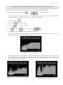
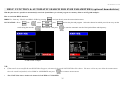
i)
Now select 1 or 2 dB/DIV (in the lower right hand corner); in this configuration you have maximum spectrum
resolution, which allows you to perfect your dish pointing. If the carriers go over the reference level, increase it by 1
or 2 dB to see all the transponder peaks.
j)
At this point, return to 5 dB/div., you could also press the MENU key and activate MAX HOLD, bringing it to ON,
press MENU again to remove the descriptions. MAX HOLD function shows in white the spectrum at the maximum
peak measured. You can therefore check that the pointing is actually at the maximum (this is a fast and precise
system, see fig. 5).
Fig.4 1 dB/DIV spectrum for fine pointing
Fig.5 MAX HOLD function, peak memory
k)
Press MENU again, remove the MAX HOLD and if necessary reselect HIGH definition, then adjust the cross
polarization to achieve the best results (this can also be carried out in MEAS, by bringing to the maximum the Noise
Margin value and the respective total quality bar).
l)
Go to measurement mode by pressing the MEAS key (level 1) and in the lower half of the screen you can see the
POWER value of the signal received (see fig. 6). Press the MORE MEAS key (level 2) and, if everything has been
stored well and you have pointed your satellite dish correctly, you should have all the measurements in the lower half
of the display, as shown in the example below (fig. 7).
N.B. By passing into MEAS you quit the SAT POINT function (and also the V.SAT function). To return, repeat the
operation from point b) to point e).
Press MORE MEAS again (level 3) and you can see the NETWORK and BOUQUET names as well as all the other
data and check to see if you are receiving the correct satellite/bouquet (N.B. Level 3 is the menu excluding the quality
and level bars, see fig. 8).
Fig.6 QPSK measurement, level 1,
with power bar
m)
Fig.7 QPSK measurement, level 2, with power
bar to the left and quality to the right, the white
arrow shows the suggested minimum quality.
Fig.8 QPSK measurement, level 3,
with N.ID plus MENU
If, in the images shown in fig. 7 or 8 lines appear instead of measurements, it means that you have carried out the
wrong satellite pointing or storing procedure. Check everything once again and the first times always refer to a dish
that is already operational. In any case go to SPAN 50 MHz and see if there is a carrier exactly in the centre of the
marker (if there isn’t you are on the wrong satellite, or band, or polarization, or symbol rate, or frequency).
N.B. With reference to fig. 8, the NETWORK name you can read in the centre to the right (e.g. NETNAME=SKY) and the
other information are those transmitted via satellite and which the instrument obtains by extracting from the MPEG data.
However, the program name, read in the centre to the left under the word MENU, e.g. PROG NAME: SKY, is the one you,
or your dealer, has pre-stored and can be varied only using a PC, opt., see page 19. Adjust only using a PC or cancel all the
respective plans using the file manager DELETE, see pages 19 and 59.
12
DM-14B & DM-14C User’s Guide
CONFIGURATION MENU
Keep pressed (hold)
for 2 seconds
13
DM-14B & DM-14C User’s Guide
SPECIAL FUNCTIONS MENU
& VIDEO TEST PATTERN GENERATOR
14
DM-14B & DM-14C User’s Guide
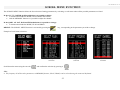
PROGRAM STORE MENU (MEMORY)
2” to Store
The MEMORY MENU is very easy to use and is required to store programs. Basically, if you rotate the encoder, you
move the cursor (grey background) to the line that corresponds to the parameter to be adjusted, for example QPSK as
shown below.
Press the encoder and it will position on the value of the parameter/status you want to adjust/store. (See example under the
frequency line). Once the data required has been adjusted, rotate the encoder and press it again to quit. Rotate the encoder
again to go to STORE? or OVERWRITE? (STORE? appears automatically if the program number to be stored in the plan
has not yet been used, alternatively the word OVERWRITE? appears, to allow you to overwrite/replace an existing
program). Press encoder again to store the program. The program number increases one number at a time, e.g. it will go to
2 (only if the programs have never been stored before, if not go ahead one at a time manually). The cursor will go to the
parameter to be adjusted (e.g. frequency for the QPSK function shown below). If you do not need to modify any other
parameters, adjust only the frequency of the next program, for example 2. Press the encoder again to quit and using the
arrow keys go to STORE, press ENTER again to store and continue until you have completed all the channels/programmes
required.
N.B. You can store without navigating on STORE? by pressing MEMORY for 2 seconds.
It is possible to store up to 199 mixed programmes for each plan in each of the various modes of the instrument (e.g.
RADIO-TV-SAT-etc even with different standards, for example France/Europe or China/Hong Kong or Russia/Europe)
To exit the PROGRAM STORE menu, press the MEAS/ESCAPE key and you will always go directly to the main menu
MEASURE. Press MEAS/SPECT again to go to SPECTRUM mode. Easy, don't you think? Remember that it is not
possible to store on identical programmes, because this is not necessary, however if you want to do this, simply move the
frequency by 25 KHz in TV and 100 KHz in SAT.
N.B. If in the MEAS menu, instead of the programme you find two small lines, you must have varied a parameter, enter in
the programme and bring it to the one required (or if you want to keep that configuration press MEMORY to store it).
The VHF channels, e.g. E10-Z10-S10 cannot be selected from the numerical keyboard, but must be selected using the UP
and DOWN keys.
REMEMBER THAT:
• You have 99 memory plans available
• You can store up to 199 mixed programs in each plan (RADIO-AN TV-QPSK-QAM- 8VSB - COFDM-DAB)
• We suggest you store a plan for each city or each type of installation; this will facilitate the registration of measurements
and data of the various installations (Data Logger) and the subsequent PC filing and print-out.
For your commodity you can note the plan and program in the table on pages 108 and 109.
15
DM-14B & DM-14C User’s Guide
PROGRAM STORE SAT MENU (MEMORY) EXAMPLES
RADIO MEMORIZATION MENU EXAMPLES
16
DM-14B & DM-14C User’s Guide
PROGRAM STORE TV MENU (MEMORY) EXAMPLES
17
DM-14B & DM-14C User’s Guide
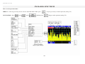
ANALOG TV MEASUREMENT
How to reach measurement mode:
DIRECT = From any previously stored "PLAN" & AN. TV "PRG" you are already in AN. TV meas (analog terrestrial TV measurement).
NAVIGATION = Press
rotate the encoder and
select
then navigate in the parameters at the top of the screen,
which can be reached directly using the respective keys, or by rotating the encoder
pr
Press
to confirm the selection.
MORE MEAS
N.B. in level 2 and 3 the picture is
interrupted every 7 seconds to
measure the audio carrier
18
DM-14B & DM-14C User’s Guide
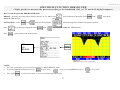
VIDEO LINES FUNCTION
( To visualise the synchro. active area and synchro oscilloscope and all the video lines)
(Useful for Analog TV and SAT and Video signals coming from a Scart socket)
THE MAIN OBJECTIVE OF THE MEASUREMENT IS: to analyse the SYNCHRO area of a video line in the amplitude dominium, to visualise eventual interferences or
reflections, as well as signal distortions and compressions.
DIRECT: To activate the H-Sync function, press the
key for two seconds.
LINE ZOOM Synch. pulse visualisation
Synch. Visualisation
in VIDEO LINES
SYNC ONLY Synch. pulse visualisation
19
DM-14B & DM-14C User’s Guide
H-SYNC FUNCTION FOR DM-14B
(Visualisation of the Analog TV & SAT synchro. active area )
DIRECT: To activate the H-SYNC function, by pressing the
Photo
Description
key for 2 seconds, select SYNC AREA using the encoder.
The picture is moved and the synchro graphic generated, locked to the signal received, to show the function “visualisation of the active synch area”.
As you can see the darker bar (black) is the synchronism, the dark grey bars are the front and back on the synchro and the lighter bar represents the chroma BURST.
a) THE MAIN OBJECTIVE OF THE MEASUREMENT is to analyse the SYNCHRO H area in time, to visualise possible interferences or reflections, as well as signal distortions and
compressions.
b) In the synchro’s lighter bars, it is much easier to recognise all the various types and quantities of reflections and/or interferences, even with moving pictures, because this active area is not
influences by the contect of the picture and it should be clean in ordeer to have a perfect picture. For example, a white line to the write of the synchro represents a “reflected signal”, which is
whiter, stronger and viceversa.
c) When there are signal compressions and/or saturations, the dark/light areas tend to unify in intensity (compression) and distort (saturation). This function shows all the phenomena described
above, which are usually difficult to see with moving pictures or with a simple SYNC visualisation.
20
DM-14B & DM-14C User’s Guide
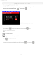
S/Nw MEASUREMENT FOR DM-14C – Being prepared
21
DM-14B & DM-14C User’s Guide
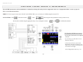
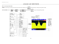
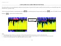
DEMODULATED “COFDM” DIGITAL TV MEASUREMENT
The COFDM measurement can be demodulated or emulated by selecting from the configuration menu (see “Configuration Menu” on page 12).
How to reach measurement mode:
DIRECT = From any previously stored "PLAN" and COFDM "PRG" you are already in COFDM meas. (digital terrestrial TV).
NAVIGATION = Press
by rotating the encoder
select
and then navigate the various parameters in the top of the screen
which can be reached using the appropriate keys, or by rotating the encoder
22
and pressing
to confirm the selection.
DM-14B & DM-14C User’s Guide
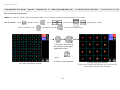
DEMODULATED “COFDM” DIGITAL TV MEASUREMENT: “CONSTELLATION”
How to reach measurement mode:
DIRECT = From any previously stored “PLAN" and COFDM "PRG” you are already in COFDM meas. (digital terrestrial TV).
NAVIGATION = Press
press
rotate the encoder
and rotate the encoder
and select
,
then press
and
Using the encoder
select “Constell.”
to activate the constellation.
To activate the zoom in the top
right hand corner
To return to measurement mode
press
COFDM–64 QAM constellation example
Constellation zoom example.
Using the UP–DOWN–ENTER keys you can select
the zoom value and the quadrant to be analyzed
23
DM-14B & DM-14C User’s Guide
.
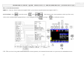
DEMODULATED “COFDM” DIGITAL TV MEASUREMENT: “SERVICES”
The COFDM measurement can be demodulated or emulated, this setting has to be selected in the configuration menu (see “Configuration Menu” on page 12).
How to reach measurement mode:
DIRECT = From any previously stored “PLAN" and COFDM "PRG” you are already in COFDM meas. (digital terrestrial TV).
NAVIGATION = Press
and with
select
, then press the following keys
To obtain the list of services contained in the COFDM multiplex use the encoder
.
press
to select a service.
Activate the INFO function to visualise the data of the chosen service.
INFO
- press
to return to measurement mode
Example of the services list contain in the COFDM multiplex.
Example of the data regarding the chosen service with
digital pictures
24
DM-14B & DM-14C User’s Guide
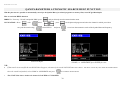
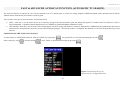
COFDM PARAMETERS AUTOMATIC SEARCH HELP FUNCTION
With this function it is possible to automatically search, with the signal connected, the main parameters to lock the terrestrial digital signal, after having selecting the plan
and program number.
How to reach HELP function:
DIRECT = from any "PLAN" and COFDM "PRG", press
NAVIGATION = Press
rotate the encoder
carry out the search
to directly enter the memorization menu.
select
select HELP? Press
press
to set the plan, program and select the channel on which you want to
to start the automatic search of the COFDM parameters.
Search example.
Once the search has finished, the cursor moves
to STORE? or OVERWRITE?
press ENTER per save.
N.B.
•
If the search is positive the word FOUND will appear, if however it was unable to find the information the words NOT FOUND will be shown. The meter can save the
data. When the search has finished, select the word STORE or OVERWRITE, then press
to finish the memorisation.
•
In the STATUS bar the word LOCKED will appear if the channel is locked. If it is not locked the word UNLOCKED appears.
25
DM-14B & DM-14C User’s Guide
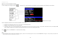
EMULATED “COFDM” DIGITAL TV MEASUREMENT
The COFDM measurement can be demodulated or emulated by selecting this mode from the configuration menu (see “Configuration Menu” section on page 12).
How to reach this measurement:
DIRECT = From any previously stored “PLAN" and COFDM "PRG" you are already in COFDM (digital terrestrial TV).
NAVIGATION = Press
ruotate the encoder
select
then navigate in the parameters at the top of the screen,
which can be reached using the appropriate keys, or by rotating the encoder
press
to confirm the selection.
N.B. Emulated OFDM measurement.
- use C/N far (f) when there are adjacent
channels
- use C/N near (n) when there are no
adjacent channels
- in the case of selective conversion
head-ends, use only C/N near (n). In
some cases C/N far (f) could measure a
C/N which is too high.
(See Configuration menu on p. 12).
26
DM-14B & DM-14C User’s Guide
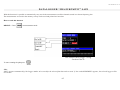
DEMODULATED “QAM” DIGITAL TV MEASUREMENT: (demodulator opt.)
How to reach this measurement:
DIRECT = from any “PLAN" and prestored QAM "PRG” you are already in QAM measurement (digital cable TV ).
NAVIGATION = Press
rotate the encoder
select
which can be reached using the appropriate keys, or by rotating the encoder
then navigate in the various parameters at the top of the screen,
pressing it
to confirm the selection.
N.B.: When you insert the QAM/8VSB demodulation board (optional), the emulated measuremnts are replaced by the demodulated ones.
27
DM-14B & DM-14C User’s Guide
DEMODULATED “QAM” DIGITAL TV MEASUREMENT: “CONSTELLATION” (demodulator opt.)
How to reach this measurement:
DIRECT = from any "PLAN" and prestored QAM "PRG" you are already in QAM measurement (digital TV via cable).
NAVIGATION = Press
rotate the encoder
Select “Constell.” press
select
press the keys
and rotate the encoder
then using the encoder
to activate the constellation.
- to activate the zoom in
the window in the upper
right-hand corner:
- press
to return to measurement
64 QAM constellation example
28
Constellation zoom example.
Using the UP-DOWN-ENTER keys you can select the
zoom value and area to be analyzed.
DM-14B & DM-14C User’s Guide
DEMODULATED “QAM” DIGITAL TV MEASUREMENT: “SERVICES” (demodulator opt.)
How to reach this measurement:
DIRECT = from any "PLAN" and prestored QAM "PRG" you are already in QAM measurement (digital cable TV).
NAVIGATION = Press
and with
select
, press the following keys:
To obtain the list of services contained in the QAM multiplex, use the encoder
and press <
to select a service.
Activate the function INFO to visualise the data of the chosen service.
INFO
- press
to return to measurement
Example of the list of services container in the
QAM Multiplex.
Example of the data relative to the chosen service
29
DM-14B & DM-14C User’s Guide
QAM PARAMETERS AUTOMATIC SEARCH HELP FUNCTION
With this function it is possible to automatically search for the Symbol Rate of a selected program in a memory Plan, in an RF QAM multiplex.
How to reach the HELP function:
DIRECT = From any "PLAN" and QAM "PRG" press
NAVIGATION = Press
with
and you directly enter the memorization menu.
select
carry out the search using
.
select HELP ?
press
set the plan and program and select the channel in which you wish to
and press
to activate the automatic search of the Symbol Rate and frequency.
Once the search has finished, the cursor moves to
STORE?, or OVERWRITE press ENTER for save.
Search example.
N.B.
If the search is successful the word FOUND will appear, alternatively the words NOT FOUND will be shown. The meter will in any case allow the memorisation.
•
Once the search has finished, select STORE or OVERWRITE and press
•
to terminate memorisation.
The STATUS bar shows whether the channel is LOCKED or UNLOCKED.
30
DM-14B & DM-14C User’s Guide
EMULATED “QAM” DIGITAL TV MEASUREMENT
The QAM measurement can be emulated or demodulated (opt.) by selecting this mode from the configuration menu (see “Configuration Menu” section on page 10).
How to reach the measurement:
DIRECT = from any previously stored “PLAN" and QAM "PRG" you are already in QAM measurement (digital cable TV).
NAVIGATION = = Press
rotate the encoder
select
and then navigate in the various parameters in the top of the screen,
which can be reached directly using the appropriate keys, or rotate the encoder
and press it
to confirm the selection.
N.B. Emulated QAM measurements
- use C/N far (f) when there are
adjacent channels
- always use C/N near (n) when there
are adjacent channels
- in the case of selective conversion
head–ends (H.E.) only use C/N
near (n), C/N far (f) in some cases
could measure a C/N which is too
high (see configuration menu on
page 12)
N.B. When you insert the QAM/8VSB demodulation board (optional), the emulated measurements are replaced by demodulated ones.
31
DM-14B & DM-14C User’s Guide
DEMODULATED “8VSB” DIGITAL TV MEASUREMENT (optional demodulator)
How to reach the measurement:
DIRECT = From any "PLAN" and pre-memorised 8VSB "PRG", go to 8 VSB measurement.
NAVIGATION = Press
by rotating the encoder
select
and then navigate in the parameters at the top of the screen,
which can be directly reached using the appropriate keys, or rotate the encoder
then press
to confirm the selection.
= FURTHER
MEASUREMENTS
N.B.
• When you insert the QAM/8VSB demodulation board (optional), the emulated measurements are replaced by demodulated ones.
32
DM-14B & DM-14C User’s Guide
DEMODULATED “8VSB” DIGITAL TV MEASUREMENT: “CONSTELLATION” (opt. demodulator)
How to reach the measurement:
DIRECT = From any "PLAN" and prememorised 8VSB "PRG" you are already in the 8VSB measurement.
NAVIGATION = Press
rotate the encoder
select “Constell.” press
select
then press
and rotate the encoder
and
to activate the constellation.
8 VSB Constellation visualisation
33
Using the encoder
DM-14B & DM-14C User’s Guide
DEMODULATED “8VSB” DIGITAL TV MEASUREMENT: “SERVICES” (optional demodulator)
How to reach the measurement:
DIRECT = From any "PLAN" and prememorised 8VSB "PRG" you are already in the 8VSB measurement.
NAVIGATION = Press
and with
select
, then press the following keys
To obtain the list of services contained in the QAM multiplex use the encoder
and press
to select a service.
Activate the INFO function to visualise the data of the chosen service.
INFO
- press
to return to measurement
Example of data in the chosen service.
Example of the list of services container in the 8VSB
Multiplex
34
DM-14B & DM-14C User’s Guide
HELP FUNCTION & AUTOMATIC SEARCH FOR 8VSB PARAMETERS (optional demodulator)
With this function it is possible to automatically search the Symbol Rate of a selected program in a memory Plan in an RF QAM multiplex.
How to reach the HELP function:
DIRECT = from any "PLAN" and "PRG" 8VSB by pressing
NAVIGATION = Press
with
select
search using the encoder
and you directly enter the memorisation menu.
.
press
and set the plan and program. Select the channel on which you wish to carry out the
select HELP ? and press
to start the automatic search of the Symbol Rate and frequency..
8VSB search example
N.B.
• If the search is successful the word FOUND will appear, alternatively the words NOT FOUND will be shown. The meter will in any case allow the memorisation.
Once the search has finished, select STORE or OVERWRITE and press
•
to terminate memorisation.
The STATUS bar shows whether the channel is LOCKED or UNLOCKED.
35
DM-14B & DM-14C User’s Guide
FM RADIO MEASUREMENT
How to reach the measurement:
DIRECT = From any previously stored “PLAN" and FM RADIO "PRG" you are already in FM RADIO mode.
NAVIGATION = = Press
and rotate the encoder
then select
and navigate in the parameters in the top of the screen,
which can be reached using the appropriate keys, or rotate the encoder
36
press
to confirm the selection.
DM-14B & DM-14C User’s Guide
DAB (Digital Audio Broadcast) MEASUREMENT
How to reach this measurement:
DIRECT = from any "PLAN" and stored DAB "PRG" you are already in DAB measurement.
NAVIGATION = = Press
rotate the encoder
select
and then navigate in the various parameters at the top of the screen,
which can be reached using the appropriate keys, or rotate the encoder
37
then press
to confirm the selection.
DM-14B & DM-14C User’s Guide
ANALOG SAT MEASUREMENT
How to reach the measurement:
DIRECT = From any previously stored “PLAN" and AN.SAT "PRG" you are already in AN. SAT mode (Analog Satellite).
NAVIGATION = = Press
rotate the encoder
select
and then navigate in the various parameters at the top of the screen,
which can be reached using the appropriate keys, or rotate the encoder
38
then press
to confirm the selection.
DM-14B & DM-14C User’s Guide
DEMODULATED DIGITAL SAT “QPSK” MEASUREMENT
How to reach the measurement:
DIRECT = From any previously stored “PLAN" and QPSK "PRG" you are already in QPSK mode (Digital Satellite).
NAVIGATION = = Press
rotate the encoder
select
and then navigate in the various parameters at the top of the screen,
which can be reached using the appropriate keys, or rotate the encoder
then press
to confirm the selection.
N.B.
The NETWORK name on the right window, e.g.
NET-NAME=SKY, and the NET.ID. table is information
transmitted via satellite by the operator, extracted from the
MPEG data. Whereas the program name in the MENU window,
e.g. PROG.NAME: SKY, is the one you, or your vendor
prestored.
39
DM-14B & DM-14C User’s Guide
DEMODULATED DIGITAL SAT “QPSK”: “SERVICES”
How to reach the measurement:
DIRECT = From any previously stored “PLAN" and QPSK "PRG", you are already in QPSK (Digital Satellite).
NAVIGATION = Press
with
select
then press the following keys
To obtain a list of the services contained in the digital transponder. Use the encoder
and press
to select a service.
Activate INFO to show the data of the chosen service.
INFO
- press
to return to measurement mode
Example of the services list contained
in the transponder SATELLITE.
Example of the relative data of the chosen service
40
DM-14B & DM-14C User’s Guide
QPSK PARAMETERS AUTOMATIC SEARCH HELP FUNCTION
With this function it is possible to automatically search for the symbol rate, with the signal connected and after having selected the plan and program number, and
then store the channel.
How to reach the HELP function:
DIRECT = From any "PLAN" and QPSK "PRG" QPSK press si
to enter directly into the memorisation menu.
NAVIGATION = Press
press
with
select
.
On which you wish to carry out the search
setthe plan and program and select the frequency and Polariz. (LNB)
select HELP ? and press
to activate the Symbol Rate automatic search.
Search example.
N.B.
•
If the search finds the data it will indicate FOUND. If the search is unsuccessful the words NOT FOUND will be shown. The instrument will, in any case prompt you to
store. Once the search has finished, select STORE or OVERWRITE and press
to terminate the store procedure.
•
The status bar shows if a channel is LOCKED or UNLOCKED.
41
DM-14B & DM-14C User’s Guide
ANALOG TV SPECTRUM
How to reach spectrum function:
DIRECT = For any previously stored "PLAN" and AN. TV "PRG" press
NAVIGATION = Press
with
select
and you go directly to analog TV spectrum mode.
and then press
to go to analog TV spectrum.
N.B.
In analog TV the 10 MHz SPAN always shows the marker on the video
carrier and in the centre of the channel in the centre of the display. The
other SPAN values always show the Marker in the centre of the display.
42
DM-14B & DM-14C User’s Guide
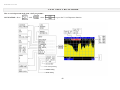
“COFDM-QAM-8VSB” SPECTRUM (Digital TV)
How to reach spectrum mode:
DIRECT = From any previously store "PLAN" and COFDM/QAM PRG, press
NAVIGATION = Press
with
select
e
and you go directly to digital TV spectrum mode.
then press
and go to digital TV spectrum.
.
43
DM-14B & DM-14C User’s Guide
FM RADIO SPECTRUM
How to reach spectrum mode:
DIRECT = from any previously stored "PLAN" and FM RADIO "PRG" press
NAVIGATION = Press
with
select
and you go directly to Radio Spectrum (analog TV).
and then press
and go to radio spectrum (analog TV).
44
DM-14B & DM-14C User’s Guide
DAB SPECTRUM (Digital Audio Broadcast)
How to reach the spectrum function:
DIRECT = from any "PLAN" and prestored DAB "PRG", press
NAVIGATION = Press
with
select
and you go directly to DAB spectrum.
and then press
45
to go to DAB spectrum.
DM-14B & DM-14C User’s Guide
ANALOG SAT SPECTRUM
How to reach spectrum mode:
DIRECT = from any previously stored “PLAN" and AN. SAT "PRG" press
NAVIGATION = Press
with
select
a
and go directly to analog SAT spectrum mode.
and then press
46
to go to analog SAT spectrum.
DM-14B & DM-14C User’s Guide
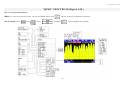
“QPSK” SPECTRUM (Digital SAT)
How to reach spectrum function:
DIRECT = From any previously stored "PLAN" and QPSK "PRG" press
NAVIGATION = Press
with
select
e
and you go directly to digital SAT spectrum.
then press
to go to digital SAT spectrums.
47
DM-14B & DM-14C User’s Guide
V.SAT SPECTRUM MODE
How to reach Spectrum mode from a SAT programme:
NAVIGATION = Press
with
select
e to go to the V. SAT Spectrum function.
48
DM-14B & DM-14C User’s Guide
SAT POINT SPECTRUM MODE (See descriptions on pages 10-11)
How to reach spectrum mode from a SAT:
NAVIGATION = Press
with
select
and go to the SAT POINT spectrum function.
49
DM-14B & DM-14C User’s Guide
Δ MRK SPECTRUM MODE
(Level or frequency “Δ” (difference) ratio measurement, with manual frequency selection)
How to reach ΔMRK spectrum mode:
DIRECT = from any previously stored “PLAN” and SAT or TV “PRG” press
To activate ΔMRK mode.
NAVIGATION = Press
Press
Press
with
and you will go directly to spectrum. Press
select the required function:
to go directly to spectrum mode. Press
with
then
Select the programme or channel or frequency.
to activate the ΔMRK function.
again to remove the menu window.
(Only analog signals)
EXAMPLE:
Measurement of the difference in level between two carriers.
N.B.
• To quit the Δ MRK function press
navigate with
• Press MENU again to remove the window.
until Δ MRK and press
50
to select OFF.
DM-14B & DM-14C User’s Guide
Δ MRK-C/N SPECTRUM MODE
(Signal/noise ratio measurement of analog signals with manual selection of noise frequencies)
How to reach ΔMRK-C/N spectrum mode:
DIRECT = From any previously “PLAN” & SAT or TV “PRG” mode, press
NAVIGATION = Press
Press
Press
with
select the mode required:
to go directly to Spectrum mode. Press
with
to go directly to spectrum. Press
with
Select the programme or the channel or the frequency required.
to activate the Δ MRK-C/N function.
to remove the menu window.
EXAMPLE:
C/N measurement in analog TV,
the MRK has been positioned
manually between the chroma and
audio carriers. The C/N measurement
takes into consideration the
measurement filter band.
(Analog signals only)
N.B.
•
•
to activate ΔMRK-C/N
To quit the Δ MRK–C/N function. Press
Press
again to remove the window.
navigate with
until you reach Δ MRK, press
51
and select OFF
DM-14B & DM-14C User’s Guide
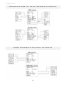
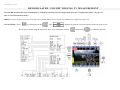
MRK BW SPECTRUM MODE
(Triple marker for the calibration of filters, amplifiers, etc. in SAT and TV band)
a) Measurement objective: Filter, amplifiers, etc. calibration in the SAT and TV band.
b) Accessories and/or necessary devices (opt.) required:
- TS1 CNG calibrated noise generator
- Assortment of very short, high quality cable, preferably already equipped with semi–professional connectors.
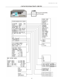
c) Connection diagram:
CONNECTION DIAGRAM
d) How to reach the measurement:
-
DIRECT = From any previously stored “PLAN” and SAT or TV “PRG”, press
-
NAVIGATION = Press
Press
c)
with
to go directly to spectrum mode.
and select the mode required.
to go directly to spectrum.
Activate the MRK.BW function by pressing
and following the procedure illustrated below.
OFF
ON
BW-PWR
EXAMPLE:
25 UHF channel filter calibration with 8 MHz band.
N.B.:
•
•
•
We suggest you store the channels in MODE – COFDM or QAM, and choose spectrum – SPAN 10 MHz to visualise the MRK
in the channel centre.
To quit MRK BW mode press
, navigate using
until you reach MRK BW and press
to select OFF.
Press
again to remove the window, or turn off.
52
DM-14B & DM-14C User’s Guide
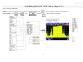
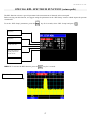
SPECTRUM FUNCTION MRK BW PWR
(Triple marker to measure the power according to the bandwidth (S.R.) of TV and SAT digital bouquets)
How to reach the Spectrum MRK BW PWR mode:
DIRECT = from any previously stored “PLAN” and SAT or TV “PRG” press
MRKBW-PWR function.
NAVIGATION = Press
with
select the desired mode:
Press
to go directly to Spectrum. Press
Press
again to remove the menu window.
with
and you directly to Spectrum. Press
with
. Select the program or channel or frequency required.
to activate the MRK BW. PWR function.
OFF
ON
BW-PWR
EXAMPLE:
PWR measurement of a transponder
NOTES:
•
The same measurement is carried out automatically in MEASUREMENT mode.
•
To quit the MRK BW-PWR function press
navigate using
until you reach MRK BW and press
•
Press again
to remove the window, or turn the instrument off and on again.
53
to select OFF.
activate the
DM-14B & DM-14C User’s Guide
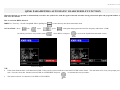
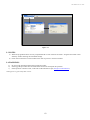
LIVE & RECALL SPECTRUM FUNCTION
This function allows you to simultaneously visualise the stored spectrum, using the SAVE operation, and the real time spectrum received at the RF input of the
instrument (live spectrum vision).
LIVE: to activate this function, in spectrum mode, press the
then press
key, recall the spectrum vision previously saved, press
, select LIVE & RECALL mode
again to remove the Menu window.
Recall spectrum
contour
N.B.:
•
The saved spectrum is shown as a contour line. The real time spectrum (live spectrum) is is shown in full white mode.
•
In LIVE & REC mode, if you adjust the Marker Frequency, the level or power measurements are carried out only on the live spectrum.
•
To return to the Recall function, select RECALL mode in the menu window.
54
DM-14B & DM-14C User’s Guide
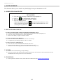
SCROLL MENU FUNCTION
The SCROLL MENU function allows the fast selection of tuning parameters by activating a scroll menu where all the possible parameters are listed.
In the AN. TV, COFDM, QAM modulations it is possible to change:
• in measurement mode the MODE, PLAN, PROG and CHAN,
• with the MEMORY function it is possible to adjust the channel.
In the QPSK, AN. SAT, DAB and FM modulations it is possible to change:
• in measurement mode the MODE, PLAN and PROG.
DIRECT: The SCROLL MENU function is activated by pressing the
key, corresponding to the parameter you wish to change.
Example of scroll menu selections:
Modulation selection
Scroll down the menu using the encoder
Program
selection
Memory plan
selection
and confirm the selection by pressing it
.
N.B.:
• The frequency all all the other parameters in MEMORY function (PLAN, PROG) can be selected using the numerical keyboard.
55
Channel
selection
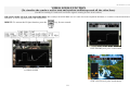
DM-14B & DM-14C User’s Guide
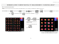
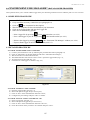
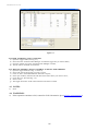
SPECIAL TV BARS SCAN FUNCTION
The BARS SCAN function activates the graphics representation of the bar spectrum. Each bar shown represents the value of the level/average power of TV programes
(analogue or digital) stored in the chosen memory plan.
This spectrum representation is useful in the TV band to easily equalise a channelised head-end output. The analog terrestrial channels are represented by a thin bar whose
height is proportional to the level of the video carrier, whereas the digital terrestrial channels are represented by a wider bar whose height is proportional to the average power of
the digital package.
How to activate the TV BARS SCAN function:
DIRECT: Select a memory plan, previously stored, then press the key
for 2 seconds. Move from one bar to another using PROG. NAME.
Figure 1
APPLICATION NOTES:
o
In the BARS SCAN function it is possible to activate the TILT measurement, ie the difference in dB between the two carriers selected and shown by the marker.
To activate the function, bring the cursor
Press the
(PROG. NAME)
o
to the word TILT, press
and select ON with the encoder
key to adjust the position of the two pilot markers for the TILT measurement. Position the markers of the carriers you want to measure by changing the programme
It is also possible to visualise for each analog bar (TV) the bar level associated with an audio carrier.
To activate this function, press the key
with
select AUDIO LEV. Press
56
and select ON.
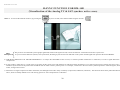
DM-14B & DM-14C User’s Guide
SPECIAL RPL SPECTRUM FUNCTION (return path)
The RPL function activates a special spectrum for the measurement of channels in the return path.
Before carrying out this function, we suggest setting the parameters in the “RPL Setup” menu to obtain improved spectrum
visualisation:
To set the “RPL Setup” parameters, press the
key for 2 seconds, select “RPL Setup? and press
Select the start
frequency
Select the stop
frequency
Select the referrence
of the level line
Select the referente
of the position line
on the screen
Select the dB/DIV
DIRECT: To activate the RPL function, press the
key for 3 seconds.
Position line
57
DM-14B & DM-14C User’s Guide
SAT FINDER – Being prepared
58
DM-14B & DM-14C User’s Guide
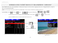
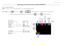
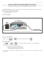
SPECIAL REFLECTOMETER BRIDGE FUNCTION
(to measure a short-circuit or interruption in coaxial cables)
a) Measurement objective: to measure a short-circuit or open-circuit or a mismatch location distance in coaxial cables.
b) Necessary accessories and devices (optional.):
a. CNG 70DL calibrated noise generator
b. Triple “F” adaptor
c) Connection diagram:
Connection diagram to carry out the measurement correctly
d) How to reach this function:
DIRECT = Press
with
select REFLECTOMETER and press
.
e) Storing the settings:
Press
with
and
to scroll the menu where it is possible to save 5 settings regarding
5 different cables. For each cable you can specify:
•
•
•
The type of cable (compact, airspac and foam),
The propagation speed VOP (from 0% to 100%)
The measurement unit required (Meters or Feet).
The five settings, once inserted, are automatically saved; all you have to do is select the cable number to recall the
cable settings.
59
DM-14B & DM-14C User’s Guide
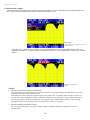
f) Measurement example:
- Recall from the menu window the previously saved cable number or insert it manually if the distribution under test
uses a type of cable with parameters which are different from those saved.
Menu setting:
Cable number, type, propagation speed and
measurement unit.
-
Using the “UP”, “DOWN” and “ENTER” keys, position Marker 1 in a curve dip and Marker 2 in the curve
dip nearest to Marker 1. Read the distance calculated by the meter in the “DISTANCE” window (see example
below).
Reflectometer measurement
example
NOTES:
1. PROPAGATION SPEED MEASUREMENT:
If the propagation speed percentage is not known (because it is not specified by the manufacturer), you can
calculate it using the reflectometer function.
With reference to the connection diagram on page 40, connect the “T” adapter at the output to 5 meters of
coaxial cable whose propagation speed is unknown, without closure resistance. Then recall the menu and
vary the propagation speed percentage until 5.0 m appears in the “DISTANCE” window. The resulting
propagation speed value obtained is the one related to the cable you are using.
2. PROGRAMMING MODIFICATION:
To vary the programming of any cable, simply change it manually and the new parameter will store
automatically.
60
DM-14B & DM-14C User’s Guide
FUNCTION: COMMAND FOR DiSEqC 1.2 ROTOR
To activate the function:
In QPSK measurement, after you have set the polarization, frequency, symbol rate and local oscillator, press
Select “Motor” , press
and
to activate the function (see figure 1).
(Figure 1)
To select the commands, position the cursor on ACTION and press
•
•
•
•
, then select the type of command using
MOVE: motor rotation per step.
GOTO: rotation in the position saved in the memory.
STORE: memorization of current position.
LIMITS RESET: cancellation of rotation limits.
61
and using the
keys
DM-14B & DM-14C User’s Guide
DESCRIPTION OF THE VARIOUS FUNCTIONS:
MOVE COMMAND:
Position the cursor on the word EAST or WEST, press the
Press the
key for a WEST rotation.
key for an EAST rotation.
GO TO COMMAND:
Position the cursor on the position number using
APPLY? And press
and select the position. Position on
, wait for the positioning to end.
STORE COMMAND:
Position the cursor on the position number using
STORE? and press
and select the position. Position on
to store.
LIMITS RESET COMMAND:
Position the cursor on APPLY? press
to cancel the the motor’s rotation limits
62
DM-14B & DM-14C User’s Guide
FAST & ADVANCED AUTOSCAN FUNCTION (AUTOMATIC TV SEARCH)
The Autoscan function is required to carry out the automatic scan of a channel plan, to search for Analog, Digital COFDM and QAM (if the optional board is fitted) TV
channels and to automatically store them in a memory plan.
You can chose two types of autoscan modes: Fast and Advanced.
•
•
FAST: when this is set, the meter carries out a search by storing in the selected memory plan, the analog and digital TV channels whose Level/Power is above the
selected threshold. Considering that all digital muxes are COFDM, no QAM/COFDM discrimination is made.
ADVANCED: when this is set, the meter, after completing the search for analog and digital TV channels, identifies the COFDM from the QAM muxes and selects and
memorises the main parameters necessary to lock onto the digital packages. Once this procedure is completed, the channels are stored in the plan that was previously
selected.
SELECTION OF THE TYPE OF AUTOSCAN:
To select FAST or ADVANCED autoscan, enter in CONFIG. by keeping the
Select Autoscan, press
with the encoder
key pressed for two seconds and rotating the encoder
select FAST or ADVANCED and quit by pressing
Figure 1: Selection of the type of
Autoscan in the Configuration menu
63
DM-14B & DM-14C User’s Guide
HOW TO ACTIVATE THE FUNCTION:
To start scanning select, using the encoder
“Auto Scan TV”, set the Destination plan (DESTIN.) and the threshold level (LEV/POW), as shown below:
Figure 2: Scan example
Set the configuration parameters in the AUTOSCAN MENU selection table:
•
•
•
Press
SOURCE: the channel plan, which is active in the meter, is automatically shown.
DESTIN.: select the Plan where to save the Auto Scan.
LEV/POW.: allows you to select the threshold value, which must be near to the levels you expect to achieve. If you select a value that is too low (for example 30dBuV
with a 90 dBuV reception level), saturations may be generated, which can cause errors in the program search.
SAVE? or OVERWRITE? To confirm and start scanning.
N:B.:
• If the destination plan is not used, the word SCAN? appears, if however the destination plan is used, the word OVERWRITE? will appear. The previously saved plan will be
cancelled and overwritten if this option is selected.
64
DM-14B & DM-14C User’s Guide
DATA LOGGER “MEASUREMENT” SAVE
With this function it is possible to automatically carry out als the measurements on all the channels stored in a chosen frequency plan.
The measurements are saved in the memory so they can be used and printed at a later date.
How to reach this function:
DIRECT = Press
in measurement mode.
This example shows Logger 1 being
saved on Plan 10.
To start scanning the plan press
N.B.:
SAVE? Appears automatically if the Logger number to be stored for the selected plan has not been used. If the word OVERWRITE? appears, the selected logger will be
overwritten.
65
DM-14B & DM-14C User’s Guide
DATA LOGGER “MEASUREMENT”: RECALL
How to reach this function:
DIRECT = Press
This function is used to recall a DATA LOGGER which has been previously stored, in order to be able to analyse it on a video screen or print it.
From LOGGER 1 to LOGGER 99
To Recall
Data logger number already saved
in the instrument’s memory
Visualization example of a Data Logger measurement in plan 6, page 61
66
DM-14B & DM-14C User’s Guide
FILE MANAGER “FILE”
The “Manager” function allows you to visualise a list of all the files stored inside the meter, to see their characteristics
and carry out maintenance.
How to reach the file manager function:
DIRECT: from any function press
select using the
keys the “FILE MANAGER” function
then press
The screen will show:
Activate the “FILE” function with
You will see the complete list of all the previously stored files
Press
and press
to scroll the whole list
to select one of the files.
EXAMPLE:
List of files contained in the meter’s memory, with the
currently used CH. PLAN called EURO. IND
highlighted.
NOTES:
FILE NAME: file name,
–
for MEM. PLAN and Spectrum files the name is provided by the PC or renamed using the meter’s keyboard
–
for CH. PLAN files the name is provided only by PC
FILE TYPE: file characteristic
–
CUSTOM: memory plan created by the user
–
CH. PLAN: standard canalization of the countries which can only be varied using a PC
–
SPECTRUM: spectrum vision stored by the user
–
LOGGER: Data Logger number created by the user
–
USER DATA: information regarding the user.
N.: sequence in which the files are stored/shown by the meter
SIZE: amount of memory occupied by the file in byte
CONTENTS: additional information
–
In MEM. PLAN it indicates the number of programmes contained and stored by the user
(Showing = currently in use)
–
For the Logger it indicates the memory plan of origin.
–
In CH. PLAN it indicates the number of channels contained (Showing = currently in use)
67
DM-14B & DM-14C User’s Guide
FILE MANAGER “INFO”
(First read the FILE MANAGER: “FILE”)
The “INFO” function allows you to visualise the characteristics of the previously selected file.
Select a file and activate INFO using the
key and press
Press
to scroll the whole list.
EXAMPLE:
List showing the contents of the programs in the “Test AGO” plan,
where programmes 11 to 22 are shown. Four are QAM, two COFDM
treeFM Radio and tree ANALOG TV. The programme name(associated
with the programme) can be typed in from the PC or on the meter’s
keyboard.
EXAMPLE:
Info of a Logger No.1 file where the PROGs from 35 to 46 are shown. ”
EXAMPLE:
Info of the configuration status of a spectrum file
EXAMPLE:
Contents (Info) of a Channel Plan file with Italian canalization.
If you want to see all the files again press
, select FILE and press
68
again.
DM-14B & DM-14C User’s Guide
FILE MANAGER “SHOW”
(First read the page FILE MANAGER: “FILE”)
The “SHOW” function allows you to visualize the measurements/spectrum relative to the program of the selected file.
Select a file and active SHOW using the
keys and press
EXAMPLE:
View of PROG 1 in memory plan 3 (when there is an antenna
signal the measurements are carried out in real time).
EXAMPLE:
View of Data Logger 1 file PROG 27. The measurements are
recalled by the prestored Data Logger
EXAMPLE:
View of file Spect 1.
If you want to see all the files again press
select “File Manager” with
and press
69
DM-14B & DM-14C User’s Guide
FILE MANAGER “RENAME”
(First read the page FILE MANAGER: “FILE”)
The “RENAME” function allows you to only change the names of MEM. PLAN and spectrum files.
Select a file, activate RENAME using the
keys and press
EXAMPLE:
Rename the MEM PLAN file called “test lab”
Select using the
keys the letter required and confirm using the
key.
The cursor will move to the next letter.
Select:
To store the file name;
If you do not want to change the original name.
Press
to confirm the selection.
To return to the visualization of all the files, select FILE using the
70
keys and press
DM-14B & DM-14C User’s Guide
FILE MANAGER “DELETE”
(First read the page FILE MANAGER “FILE”)
The “DELETE” function allows you to cancel a custom file, logger or spectrum from the meter’s memory. This
function allows you to remove old memory plans, data loggers and spectrums which are no longer used.
Select a File, activate DELETE using the
keys and press
EXAMPLE:
Delete the MEM. PLAN file called “hotel 01”
Select:
To eliminate the selected file;
If you do not want to eliminate the selected file.
Press
to confirm the selection.
To return to the visualization of all the files, highlight FILE using the
press
71
keys and
DM-14B & DM-14C User’s Guide
FILE MANAGER “DEFRAG”
(First read the FILE MANAGER “FILE” page)
The “DEFRAG” function allows you to optimize and compact the meter’s memory.
We suggest using this function after you have repeatedly created and cancelled memory plans, Data Loggers and
spectrums.
Activate the DEFRAG function using the
With the
keys and press
keys select:
To defragment the memory
If you do not want to defragment the memory
Press
to confirm.
To return to the visualization of the all the files, highlight FILE and press
N.B.: When the instrument is turned on, or is being used, it will send a message, which appears on the
monitor suggesting when it may be necessary to carry out the DEFRAG operation.
72
DM-14B & DM-14C User’s Guide
APPENDICES
A1 - TECHNICAL SPECIFICATIONS
ANALOG TV
•
•
•
•
•
•
•
•
•
•
•
•
•
•
•
•
Frequency band: 4–878 MHz including IF 38.0/38.9/45.75 MHz which can be measured, seen and heard on the TV monitor
Direct selection of: memory plan, program, chan., dc at RF IN, freq., with numeric keyboard
Memorization of: memory plan, program, channel, dc at RF IN, frequency, audio carrier, standard, frequency offset
Frequency resoltuion: 62 KHz
Input impedance: 75 ohm
Interchangeable input connector: "F" or "IEC" or "BNC" ("N" optional)
Power supply at RF IN: in the TV band for pream.: OFF, +5, +12, +15, +18, +24 V (0.3 A)
RF IN automatic preamplifier: this is automatically inserted when the RF input level is less than the set thresholds, it is
automatically calculated from the measurement and the activation is shown by the relative LED on the front panel near the RF input
Analog measurement dynamic range at RF input: from 20 to 130 dBuV, from –40 to + 70 dBmV (selectable), with limit
indication: level too low, level too high
Measurement resolution: 0.1 dB
Level measurement accuracy: 1 dB typ. (1,5 max) with SW correction (after 5 minutes’ warm–up)
A/V ratio measurement accuracy: 1.5 dB typ. (2 dB max)
Measurement filter bandwidth: 130 KHz at –3 dB
Measurement stability versus temperature between –10 and 50°C: 0.03 dB/°C
Multi–standard: M–N–B–G–I–D–K (audio L opt.)
TXT: teletext
FM RADIO
• Frequency band: tunable from 4 to 878 MHz (default 88–108)
• Direct selection of: memory plan, program, dc at RF IN, frequency, with numerical keyboard
• Memorization of: memory plan, program, channel, dc at RF IN, frequency, audio carrier, standard
• Frequency resolution: 62 KHz
• Audio demodulation: FM
• Demodulation filter bandwidth:
100 KHz @ –3 dB.
Audio heard with built–in loudspeaker: 0.5 W adjustable volume
ANALOG SAT
• Frequency band: 930–2250 MHz
• Direct selection of: memory plan, program, frequency, LNB voltage, DiSEqC, with numerical keyboard
• Memorization of: memory plan, program, LNB, DISEqC, local oscillator frequency, trasponder frequency, audio carrier, video
polarity
• Frequency resolution: 0.1 MHz
• Input impedance: 75 ohm
• Interchangeable input connector: "F" or "IEC" or "BNC" ("N" optional)
• Power supply at RF input: in the SAT band for LNB: OFF, +13, +18, 22 KHz (0.3 A)
• DiSEqC: 4, 8, 12 or 16 polarizations, DiSEqC "a.b.c.d" already pre–programmed in sequence and very easy to use. It can power any
type of LNB (analog or DiSEqC, single or dual feed) and any type of multiswitch and SAT router (analog or DiSEqC with 4, 8, 12, 16
inputs)
• LNB current measurement: from 1 to 300 mA
• RF IN automatic preamplifier: this is automatically inserted when the RF input level is less than the set thresholds, it is
automatically calculated from the measurement and the activation is shown by the relative LED on the front panel near the RF input
• Analog measurement dynamic range at the RF input: from 25 to 120 dBuV, from –35 to +60 dBmV (selectable) with limit
indications: level too low, level too high
• Measurement resolution: 0.1 dB
• Level measurement accuracy: 1.5 dB typ. (2.5 dB max.) with software correction (after 5 minutes warm–up)
• Measurement filter bandwidth in SAT mode: 4 MHz at –3 dB
• Measurement filter bandwidth in V.SAT mode: 0.2 MHz at –3 dB (opt.)
• Picture demodulation filter bandwidth: 27 MHz
• Measurement stability versus temperature between –10 and 50°C: 0.03 dB/°C
• LNB L.O. frequency selection: continuous from 0 to 20.000 MHz, for "L" bands (direct IF–SAT reading), "S", "C", "KU”, "KA";
• Audio demodulation: from 4.5 to 8.5 MHz
• TXT: teletext
73
DM-14B & DM-14C User’s Guide
QAM & 8VSB (Emulated)
(supplied when optional DEMODULATED QAM & 8VSB board is not inserted)
• QAM frequency band: 4–878 MHz
• Direct selection of: memory plan, program, chan., dc at RF IN, freq., with numeric keyboard
• Memorization of: memory plan, program, channel, dc at RF IN, frequency, symbol rate, frequency offset
• Frequency resolution: 62 KHz
• Input impedance: 75 ohm
• Interchangeable input connector:
"F" or "IEC" or "BNC" ("N" optional)
• Power supply at RF IN: in the TV band for pream.: OFF, +5, +12, +15, +18, +24 V (0.3 A)
• RF IN automatic preamplifier: this is automatically inserted when the RF input level is less than the set thresholds, it is
automatically calculated from the measurement and the activation is shown by the relative LED on the front panel near the RF input
• Power measurement dynamic range at the RF input: from 30 to 126 dBuV, from –30 to + 66 dBmV (selectable) with limit
indications: level too low, level too high
• Power measurement resolution: 0.1 dB
• Power measurement accuracy: 1 dB typ. (2 dB max.) with software correction (after 5 minutes' warm-up)
• C/N ratio measurement accuracy: 1.5 dB typ. (2,5 max.) with noise measurement on the adjacent first free channel, selectable
• Measurement filter bandwidth: 130 KHz a –3 dB
• Measurement stability versus temperature between –10 and 50°C: 0.03 dB/°C
• BER evaluation: up to 1 x 10⁻⁸ (emulated)
• TEST PASS–MARG–FAIL: digital signal evaluation (exclusive ROVER algorithm)
– "C/N NEAR" (with measurement of "N" noise on adjacent channel)
– "C/N FAR" (with measurement of "N" noise on first free channel) selectable and storable
• Multiplex flatness measurement: from 0 to > 20 dB. 1 dB typ. (1.5 max)
QAM (Demodulated Annex A–B–C)
(optional)
•
•
•
•
•
•
•
•
QAM frequency band: 47–878 MHz
Direct selection of: memory plan, prog., chan., dc at RF IN, freq., with numerical keyboard
Memorization of: memory plan, program, channel, dc at RF IN, frequency, constellation, symbol rate, frequency offset
Frequency resolution: 62 KHz
Input impedance: 75 ohm
Interchangeable input connector: "F" or "IEC" or "BNC" ("N" optional)
RF input power supply: in the TV band for preamp.: OFF, +5, +12, +15, +18, +24 V (0.3 A)
RF IN automatic preamplifier: this is automatically inserted when the RF input level is less than the set thresholds, it is
automatically calculated from the measurement and the activation is shown by the relative LED on the front panel near the RF input
• Power measurement dynamic range at the RF input: from 30 to 126 dBuV, from –30 to + 66 dBmV (selectable) with limit
indications: level too low, level too high
• Power measurement resolution: 0.1 dB
• Power meas.accuracy: 1 dB typ. (2 dB max.) with SW correction (after 5 minutes' warm–up)
• Measurement filter BW: 130 KHz at –3 dB
• Measurement stability versus temperature between –10 and 50°C: 0.03 dB/°C
• Symbol rate selection: from 1000 to 9000 KS/s in 1 KS/s steps
• Min. power to lock the QAM demodulator:
– at 64QAM = 34 dBuV ±2
– at 128QAM = 36 dBuV ±2
– at 256QAM = 38 dBuV ±2
• MER ratio measurement accuracy:
– 64 QAM up to 34 dB, ±1 dB typ. (2 dB max) with power > 45 dBuV
– 128 QAM up to 36 dB, ±1 dB typ (2 dB max) with power > 47 dBuV
– 256 QAM up to 38 dB ±1 dB typ (2 dB max) with power > 49 dBuV
• BER measurement:
– bBER up to 1 x 10⁻⁸
– aBER (after R.S.) at 1 x 10 - 8
– Error counter, per sec.
– Severe total error counter
• Automatic digital signal quality TEST: PASS–MARG–FAIL
• Spectrum inversion: automatic
• Constellation picture: 64–128–256 with zooms x1, x2, x4
• TXT: teletext
74
DM-14B & DM-14C User’s Guide
8VSB (Demodulated)
•
•
•
•
•
•
•
•
8VSB frequency band: 47–878 MHz
Direct selection of: memory plan, program, chan., dc at RF IN, freq., with numerical keyboard
Memorization of: memory plan, program, channel, dc at RF IN, frequency, constellation, symbol rate, frequency offset
Frequency resolution: 62 KHz
Input impedance: 75 ohm
Interchangeable input connector: "F" or "IEC" or "BNC" ("N" optional)
Power supply at RF IN: in the TV band for preamp.: OFF, +5, +12, +15, +18, +24 V (0.3A)
RF IN automatic preamplifier: this is automatically inserted when the RF input level is less than the set thresholds, it is
automatically calculated from the measurement and the activation is shown by the relative LED on the front panel near the RF input
• Power measurement dynamic range at the RF input: from 35 to 126 dBuV, from –25 to + 66 dBmV (selectable) with limit
indications: level too low, level too high
• Power measurement resolution: 0.1 dB
• Power meas.accuracy: 1 dB typ. (2 dB max.) with SW correction (after 5 minutes' warm-up)
• Measurement filter BW: 130 KHz at –3 dB
• Measurement stability versus temperature between –10 and 50°C: 0.03 dB/°C
• MER & BER measurement
• Constellation vision
• 8VSB symbol rate selection:
from 1000 to 8000 MS/s (1 KS/s steps)
(bit rate from 2000 to 6000 Mb/s)
COFDM (Emulated)
(supplied, selectable and storable)
• COFDM frequency band: 4–878 MHz
• Direct selection of: memory plan, program, chan., dc at RF IN, freq., with numerical keyboard
• Memorization of: memory plan, program, channel, dc at RF IN, frequency, number of carriers, constellation, channel width, offset
freq.
• Frequency resolution: 62 KHz
• Storable offset frequency: in 62 KHz steps
• Input impedance: 75 ohm
• Interchangeable input connector: "F" or "IEC" or "BNC" ("N" optional)
• Power supply at RF IN: in TV band for pream.: OFF, +5, +12, +15, +18, +24 V (0.3 A)
• RF IN automatic preamplifier: this is automatically inserted when the RF input level is less than the set thresholds, it is
automatically calculated from the measurement and the activation is shown by the relative LED on the front panel near the RF input
• Power measurement dynamic range at the RF input: from 35 to 126 dBuV, from –25 to + 66 dBmV (selectable) with limit
indications: level too low, level too high
• Power measurement resolution: 0.1 dB
• Power measurement accuracy: 1 dB typ. (2 dB max.) with software correction (after 5 minutes' warm–up)
• C/N ratio measurement accuracy: 1.5 dB typ. (2,5 max.) with noise measurement on the nearest adjacent free channel
• Measurement filter bandwidth: 130 KHz at –3 dB
• Measurement stability versus temperature between –10 and 50°C: 0.03 dB/°C
• aBER measurement: up to 1x10⁻⁸ (emulated)
• TEST PASS–MARG–FAIL: digital signal evaluation (exclusive ROVER algorithm)
– "C/N NEAR" (with measurement of "N" noise on adjacent channel)
– "C/N FAR" (with measurement of "N" noise on the first free channel) select.and storable
• Multiplex flatness measurement: from 0 to > 20 dB. 1 dB typ. (1.5 max)
COFDM (Demodulated)
(supplied, special for MFN & SFN networks with ECO and PREECO at 0 dB)
• COFDM frequency band: 47–878 MHz
• Direct selection of: memory plan, program, chan, dc at RF IN , freq, with numerical keyboard
• Memorization of: memory plan, prog., channel, dc at RF IN , frequency, number of carriers, channel width, offset–frequency
• Frequency resolution: 62 KHz
• Storable offset frequency: in 62 KHz steps
• Input impedance: 75 ohm
• Interchangeable input connector: "F" or "IEC" or "BNC" ("N" optional)
• Power supply at RF IN: in TV band for preamp.: OFF, +5, +12, +15, +18, +24 V (0.3 A)
• RF IN automatic preamplifier: this is automatically inserted when the RF input level is less than the set thresholds, it is
automatically calculated from the measurement and the activation is shown by the relative LED on the front panel near the RF input
• Power measurement dynamic range at the RF input: from 30 to 126 dBuV, from –30 to + 66 dBmV (selectable) with limit
indications: level too low, level too high
• Power measurement resolution: 0.1 dB
75
DM-14B & DM-14C User’s Guide
• Power measurement accuracy: 1 dB typ. (2 dB max.) with SW corr. (after 5 mins' warm-up)
• MER measurement accuracy: up to 30/32 dB
accuracy, 1 dB typ. (1.5 dB max), with > 40 dBuV power
• Measurement filter BW: 130 KHz at –3 dB
• Measurement stability versus temperature between –10 and 50°C: 0.03 dB/°C
• BER measurement before and after Viterbi:
– bBER up to 1 x 10⁻⁵
– aBER up to 1 x 10⁻⁸
• Automatic recognition & visualization of: HP/LP rate, guard interval, constellation
– Rate: 1/2, 2/3, 3/4, 5/6, 7/8
– Guard interval: 1/4, 1/8, 1/16, 1/32
– Constellation: QPSK, 16 QAM, 64 QAM
• Automatic digital signal quality TEST: PASS–MARG–FAIL
• CSI measurement: percentage of non–valid carriers 0–100%
• Spectrum inversion: automatic
• Constellation picture: QPSK–16 QAM– 64 QAM with x1, x2, x4 zooms.
• TXT: teletext
QPSK (Demodulated)
•
•
•
•
•
•
•
•
Frequency band: 930–2250 MHz
Direct selection of: memory plan, prog., LNB, DiSEqC, transponder freq, with numerical keyboard
Memorization of: memory plan, program, LNB, DISEqC, local oscillator frequency, trasponder frequency, standard, Symbol Rate
Frequency resolution: 0.1 MHz
Input impedance: 75 ohm
Interchangeable input connector: "F" or "IEC" or "BNC" ("N" optional)
Power supply at RF IN: in the SAT band for LNB: OFF, +13V, +18V, 22 KHz (0.3 A)
DiSEqC: 4, 8, 12 or 16 polarizations, DiSEqC "a.b.c.d" already pre–programmed in sequence and very easy to use. It can power any
type of LNB (analog or DiSEqC, single or dual feed) and any type of multiswitch and SAT Router (analog or DiSEqC with 4, 8, 12,
16 inputs)
• LNB current or preamp meas.: 1 to 300 mA
• RF IN automatic preamplifier: this is automatically inserted when the RF input level is less than the set thresholds, it is
automatically calculated from the measurement and the activation is shown by the relative LED on the front panel near the RF input
• Digital power measurement dynamic range at the RF input: from 30 to 123 typ. (126 max.) dBuV, from –30 to +63 typ. (66 max.)
dBmV (selectable) with limit indications: level too low, level too high
• Power measurement resolution: 0.1 dB
• Power measurement accuracy: 1.5 dB typ. (2.5 dB max.) with software correction (after 5 minutes’ warm–up)
• MER and Noise Margin measurement accuracy: 0.5 dB typ. (1 dB max) with SW corr.
• Measurement filter bandwidth in SAT mode: 4 MHz at –3 dB
• Measurement stability versus temperature between –10 and 50°C: 0,1 dB/°C
• QPSK Symbol Rate setting: 2–45 MS/s, in 1 KS/s steps
• BER measurement before and after Viterbi:
– bBER up to 1 x10⁻⁶
– aBER up to 1 x10⁻⁸
• FEC, automatic recognition & visualiz. of value: FEC 1/2, 2/3, 3/4, 4/5, 5/6, 6/7, 7/8, 8/9
• Automatic Quality TEST: FAIL- MARG - PASS
• Noise margin measurement: from –2 to 12 dB with special algorythm which automatically considers the FEC value
• LNB local oscillator frequency: continuous from 0 to 20.000 MHz, for bands, "L" (direct IF–SAT reading), "S", "C", "KU", "KA";
• QPSK standard selection: DVB/DSS
• LNB frequency measurement: 0 to 3 MHz
• TXT: teletext
CONSTELLATION
Constellation visualization of COFDM, QAM and 8VSB digital programmes, with x1, x2 and x4 zooms, and automatic refreshment.
MPEG2 F.T.A. & NET. ID.
Mod. DL-14 provides all the same information with the images (audio and video) of all the F.T.A. digital programmes.
• MPEG signal format: ETS 300 421
• Video resolution: 720x576, 704x574, 544x576, 480x576, 352x576
• Video decompression type: MPEG1, MPEG2@ML (I, P & B frame decoding)
• Out TV stand.: PAL, NTSC, SECAM (select.)
• Audio decompression: MPEG layer II (MUSICAM)
76
DM-14B & DM-14C User’s Guide
VIDEO ANALYSIS & MEASUREMENTS (SYNCHRO & I.T.S. VIDEO LINES)
• Visualization of the synchro and burst, according to time and amplitude
• Selection and visualization of all the video lines and ITS expandible with Zoom
• S/N-W measurement
TV SPECTRUM ANALYSIS
•
•
•
•
•
•
•
•
•
•
Frequency band: 4–878 MHz
Span in TV band: 2–5–7–10–20–50–100– 200–500–FULL–VHF–UHF
Span in RP band: 2–5–7–10–20–50–RP (4–65 MHz)
dB/div: 1–2–5–10
Dynamic range: >60 dB
Measurement resolution: 0.1 dB
Measurement filter bandwidth: TV 130 KHz at –3 dB
Reference level: from 0 to 130 dBµV, from –60 dBmV to +70 dBmV
Spectrum setting: automatic or manual, selectable
In automatic spectrum mode: Passing from measurement (MEAS) to spectrum (SPECT) you can immediately see only the
spectrum of the program/channel received perfectly centred and automatically aligned to the reference level
• Spectrum parameters set automatically:– Ref level/power indication at the top of the display (corresponding to the attenuator in old
instruments)
– Span: 10 MHz
– dB/division: 10 dB/
• Frequency/level marker position:
– For digital signals in channel centre
– For analog signals on video carrier
• Measurement band selection & correlation of analog or digital signals: shown on display
• Other spectrum selections:
– MARKER: OFF, ON, C/N per segnali analogici (2 markers to measure BW power)
– MARKER BW: OFF, ON, BW POWER
(1+2 markers for chan. filter calibration)
– MAX HOLD: OFF, ON
– PICTURE: only contours or full
– DEFINITION: high 320 points, medium 160 points, low 80 points
– BUZZER: OFF, MRK LEVEL
• Possibility of storing 99 spectrum pictures (Data Logger)
SAT SPECTRUM ANALYSIS
•
•
•
•
•
•
•
•
•
Frequency band: 930–2250 MHz
Span: 5–10–20–50–100–200–500–FULL
dB/div: 1–2–5
Dynamic range: >30 dB
Measurement resolution: 0.1 dB
Measurement filter bandwidth: SAT 4 MHz at –3 dB, VSAT 0.2 MHz at –3 dB
Reference level: from 0 to 126 dBµV, from –60 dBmV to +66 dBmV
Spectrum settings: automatic or manual, selectable
Automatic spectrum mode: Passing from measurement (MEAS) to spectrum (SPECT) you can immediately see only the spectrum
of the program/channel received perfectly and automatically aligned to the reference level
• Spectrum parameters set automatically: – Ref level/power indication at the top of the display (corresponding to the attenuator in
old instruments)
– Span: 50MHz
– dB/division: 5 dB
– Freq./level marker position: in centre band
– Measurement band selection and correlation of analog or dig. signals: shown on the display
• Other selectable spectrum parameters:
– MARKER: OFF, ON, C/N for analog signals (2 markers to measure bandwidth)
– MARKER BW: OFF, ON, BW POWER (1+2 markers to measure the power/bandwidth)
– MAX HOLD: OFF/ON (peak memory)
– PICTURE: contours or full white
– DEFINITION: high 320 points, medium 160 points, low 80 points, selectable
– V.S.A.T (very small aperture terminal) spect.
– SAT POINTING: automatic optimum setting for satellite dish pointing
– BUZZER: OFF, MRK POWER
• Possibility of storing 99 spectrums (Data Logger)
77
DM-14B & DM-14C User’s Guide
OTHERS
• RF input power feed:
– In the TV band for preamplifier:
OFF, +5, +12, +15, +18, +24 V (0.3 A)
– In the SAT band for LNB: OFF, +13 V, +18V, 22 KHz (0.3 A)
• DiSEqC: 4, 8, 12 or 16 polarizations, DiSEqC "a.b.c.d" already pre–programmed in sequence and very easy to use. It can power any
type of LNB (analog or DiSEqC, single or dual feed) and any type of multiswitch (analog or DiSEqC with 5, 9, 13, 17 cables)
• RF IN automatic preamplifier: this is automatically inserted when the RF input level is less than the set thresholds, it is
automatically calculated from the measurement and the activation is shown by the relative LED on the front panel near the RF input
• Power supply:
– Built–in rechargeable batteries: 12 V x 7 A (LEAD GEL)
– Voltage load: 17/20 Vac or 20/24 Vdc (1.1 A), (connector: Ø 5,5 x 2,2)
– AC/AC adapter: 230 Vac (117V opt.),
output: 17 Vac (supplied)
• LNB current or Preampl meas.: 1 to 300 mA
• Buzzer: level or quality parameter selection
• Battery duration at 25°C: 5 hours in TV AN at 20°, 4 hours in digital SAT depending on LNB consumption.
• low battery indicator: with acoustic signalling and shown on TFT and auto turn–off from micro-controller
• Indication of battery load charge: when instrument is turned on
• Battery recharge time: 3 hours for approx 50% capacity, 6/8 hours for complete charge (12 hrs. advisable), with automatic switching
on slow maintenance charge and LED charge and FULL charge indication
• Instrument size: H 135 x L 330 x D 380 mm
• Instrument weight: 6.5 Kg including battery, (bag and accessories 1 Kg approx.)
• Casing structure: plastic–coated aluminium and silicon rubber, rain–, dust– and shock-proof
• RS232 interface: for communications with PC; possibility of SW up–grades downloaded from Internet, (memory plan configuration
control, print–outs, Data Logger etc. optional)
• USB interface: with optional adaptor
• Audio/video input/output: Scart (Peritel) socket (demod. video outputs/with OSD + spect PIN 19)
• Picture display: 5.5" TFT color for DM-14C, CRT 5.5” B/W for DM-14B PAL (encased and antishock)
(encased and anti-shock). Please note that for 5,5” TFT monitors if Pixel are turned off the tollerance, according to the manufacturer, is 1
pixel in the centre and 2 pixels around the perimeter.
• Auto–off timer: after 5 mins without use (select-able on/off, always starts up from last fuction)
• Auto–test menu: Self–test of main internal digital circuits
• RF input overload protection: electronic up to 60 Vac, or total with manual side safety switch
• DC AT RF IN (LNB) current measurement: 0–300 mA accuracy, 3 mA typ. (5 max)
• TXT (teletext) selection and visualization
• Measurement voltmeter: AC 110 V max, DC +110 V max applied to RF input
• Video test generator: to check CRT linearity and for modular an CCT network tests. Available at scart socket, on pin 19
• File manager: to maintain internal data files (canalizations, memory plans, saved spectrums), data logger, etc.
• Defrag function: for memories defrag
BATTERY
•
•
•
•
Battery duration at 25°C: 5 hours in TV, 2 hours in digital SAT according to LNB consumption.
Low battery indicator: with acoustic signalling and shown on the CRT and auto turn-off from micro-controller
Indication of battery load charge: when instrument is turned on
Battery recharge time: 1 hour for 50% capacity, 4/6 hours for complete charge, with automatic switching on slow maintenance
charge and LED charge and FULL charge indication.
STRUCTURE
• Instrument size: H 160 x L 280 x D 370 mm
• Instrument weight: 6,5 Kg with battery, bag and accessories 1 Kg approximately
• Casing structure: plastic-coated aluminium and silicon rubber, rain–, dust– and shock–proof.
INPUTS
• RS232 interface: for communications with PC; possibility of SW up-grades downloaded from Internet, (memory plan configuration
control, print-outs, Data Logger etc. optional)
• USB interface: with optional adaptor
• Audio/video input/output: with Scart socket 19 (Demodulator video output./with OSD + spectrum)
78
DM-14B & DM-14C User’s Guide
MEASUREMENTS
• DC AT RF IN (LNB) current measurement: 0–300 mA, precision ± 3 mA typ. (5 max)
• TXT selection and visualisation
• Voltmeter measurement: AC 110V max, DC +110V max, applied at the RF input, precision ± 1 V typ. (2 V max)
IMPORTANT:
Please kindly note that if there are pixels turned off on the 5.5” TFT Monitor, fitted in ROVER
instruments, the tollerance indicated by the manufacturer is 1 pixel in the centre area and 2 pixels
around the parameter.
79
DM-14B & DM-14C User’s Guide
A2 – SMART PROGRAM
HOW TO INSTALL THE SMART PRO PROGRAM IN YOUR PC.
a) Download the S.M.A.R.T. program from the ROVER website (www.roverinstruments.it) on the
product support page, to your computer desktop. The file containing the SMART program is
zipped and can unzipped using the Unzip® or Winzip® computer programs.
b) The unzip program will ask for a password, which can be obtained by contacting ROVER by
telephone or e-mail [email protected]. You will be asked to supply your instrument’s
serial number.
c) Open the SETUP file in the Kit Installation Smart folder.
d) Follow the automatic procedure which will guide you through the installation: you can modify
the installation folder; if the name of this folder is not modified, the program creates a folder
called SmSw.
e) The SMART program inserts an icon in the program list of your computer and an icon
connecting to your desktop. By clicking on this icon, the SMART program strarts up
automatically.
HOW TO DOWNLOAD THE EXACT UPGRADE FROM INTERNET
-
-
Download the upgrade from internet (www.roverinstruments.it), by going to the product support
page and selecting the upgrade relative to your instrument. Save it on your computer desktop.
The file containing the upgrade firmware is zipped and must be unzipped using computer
programs Unzip® or Winzip®.
The unzip program will ask for a password, which can be obtained by contacting ROVER by
telephone or e-mail [email protected]. You will be asked to supply your instrument’s
serial number.
Expand the upgrade file and save it on your PC (for example on your desktop).
80
DM-14B & DM-14C User’s Guide
1.0 HOW
TO CONNECT YOUR MEASURING INSTRUMENT TO A PC
This procedure allows the SMART program to recognise the instrument connected to the PC.
1.1 SIMPLE PROCEDURE
INSTRUMENT – PC CONNECTION
1.
2.
3.
4.
5.
Connect your instrument to the PC
Turn on your instrument
Start the Smart program
Click
(See Instrument Bar Description) (also see 1.4 warning paragraph)
Follow the instructions shown on the screen until it is complete.
1.2 DETAILED PROCEDURE
1.2.1 CONNECTION BETWEEN INSTRUMENT & PC
a) Connect the instrument to the PC using the Null Modem cable
b) Turn on your instrument.
c) Start the SMART program.
d) From the instrument bar, click on the words “Instrument” and “Connect Instrument”, (Figure 1.1) (see paragraph 1.4
“Warning”)
e) In the “Instrument Type” window, select your instrument’s model and confirm your selection using the key “OK”.
f) The “Port Setting” window will open (serial port configuration) where you can select the port number (COM) to which
your instrument is connected. The other settings can be changed, but it is best not to use the preselected ones.
Confirm by pressing the “OK” key to activate instrument connection.
Figure 1.1
1.3 NOTES
a)
If the procedure is carried out correctly, the bar below will show the instrument data (instrument model, serial number
and firmware version).
1.4 WARNINGS
a) If the up-grade procedure does not work, check connections and repeat the operation.
b) If this operation continues to fail, contact Ro.Ve.R Laboratories SpA ([email protected]).
81
DM-14B & DM-14C User’s Guide
2.0 FIRMWARE UPGRADES
This procedure allows you to upgrade your meter with the last Firmware version available on our website.
2.1 SIMPLIFIED PROCEDURE
FIRMWARE UP-GRADE
1. Download the internet up-grade.
3. Connect your instrument to a PC.
4. Start the SMART program.
5. Click on
(See instrument bar description) (also see paragraph 2.4
WARNINGS).
6. Follow the instructions on the screen until the procedure has been completed.
2.2 DETAILED PROCEDURE
2.2.1 HOW TO DOWNLOAD FIRMWARE UP-GRADES FROM INTERNET
a)
Download from internet web site www.roverinstruments.it, in the Technical support section, the up-grade regarding
your instrument and save it on the desktop of your PC,
b) The file containing the firmware is zipped; un-zip it using computer programs Unzip®* or Winzip®*,
c) The unzip program will ask for a password which is provided directly by Ro.Ve.R Laboratories SpA, by telephone or email ([email protected]); remember to provide your meter’s serial number,
d) Unzip the up-grade file and save it on your PC (for example on your desktop).
2.2.2 HOW TO PREPARE YOUR INSTRUMENT FOR AN UP-GRADE
a) Connect your instrument to the PC’s serial port using the RS 232 Null Modem cable
b) Turn on your instrument and connect it to the mains.
2.2.3
HOW TO UP-GRADE YOUR INSTRUMENT USING A PC
a) Start up the Smart Pro program,
b) Click on “Instrument” and “Up grade Firmware” in the instrument bar, (Figure 2.1) (Also see paragraph 2.4
WARNINGS)
c) In the “Open” window, select the file you want to use for the up-grade and confirm your selection by pressing the
“open” key,
d) The “Upgrade Firmware” window will open where you can select the instrument model and the port (COM) to which it
is connected,
e) Press “Command Upgrade” to start the up-grade.
82
DM-14B & DM-14C User’s Guide
Figure 2.1
2.3 NOTES
a)
When the up-grade has been correctly completed the PC screen will show the words “Program Successful” and a
summary window showing the instrument settings.
b) Check the new firmware version number in the Start Up screen or self-test windows.
2.4 WARNINGS
a)
b)
c)
Do not use the instrument during the up-grade procedure.
If the up-grade procedure does not work check connections and repeat the operation
If the operation continues to fail, contact Ro.Ve.R Laboratories SpA ([email protected]).
*All logos are registered by their owners.
83
DM-14B & DM-14C User’s Guide
3.0 GET
SCREEN
This function allows you to transfer any data display from your instrument to a PC.
3.1 SIMPLIFIED PROCEDURE
GET SCREEN
1. Carry out all the necessary connections (see paragraph 1.0)
1. Click on
(See instrument bar description)
2. Wait for the display to appear on the PC monitor.
3. Select one of two options:
- Print from the PC by pressing
from the instrument bar (see 3.2.2);
- Save it on the PC by pressing
from the instrument bar (see 3.2.3)
(a bitmap file is generated).
3.2 DETAILED PROCEDURE
3.2.1
a)
b)
c)
HOW TO TRANSFER A DISPLAY FROM INSTRUMENT TO PC
Connect your instrument to a PC by following the procedure described in paragraph 1.0.
Click on “Tools” and “Get Screen” on the instrument bar.
Wait for the display to appear on the PC monitor.
3.2.2 HOW TO PRINT THE DISPLAY
a) Click on “File” on the instrument bar and select “Print Setup”.
b) Configure the print settings and press “OK” to confirm.
3.2.3 HOW TO SAVE THE DISPLAY
a) Click on “File” on the instrument bar and select “Save As”.
b) Chose a location where you want to save the file and press “Save”.
SMART will save the display obtained from the meter in bitmap format.
3.3 NOTES
a) Pictures are saved with file type .bmp (Bitmap),
b) Only the spectrums and measurements graphics, generated by the instrument, can be transferred to the PC;
demodulated television pictures can not be transferred.
3.4 WARNINGS
a)
If this operation continues to fail, contact Ro.Ve.R Laboratories SpA ([email protected]).
84
DM-14B & DM-14C User’s Guide
4.0 “INSTRUMENT
FILE MANAGER” (DATA LOGGER TRANSFER)
This operation allows you to transfer a Data Logger from your measuring instrument to a PC and then print it or save it in a file.
4.1 SIMPLIFIED PROCEDURE
HOW TO TRANSFER A DATA LOGGER FROM AN INSTRUMENT TO A PC
1. Carry out all the necessary connections (see paragraph 1.0)
2.
3.
4.
5.
Click on
(See instrument bar description)
Wait for the complete file list to download on your instrument
Click on the Logger folder and open the Logger file
Select one of the following options:
- Print a logger file by pressing
on the instrument bar (see 4.2.2)
- Save a data logger in your PC by pressing
in the instrument bar (see 4.2.3)
- Delete a data logger by pressing
in the “Instrument File Manager” window (see 4.2.4)
- Export a Data Logger in an Excel or Word file (see 4.2.5).
4.2 DETAILED PROCEDURE
4.2.1
a)
b)
c)
d)
e)
f)
HOW TO TRANSFER A DATA LOGGER
Connect your instrument to a PC by following the procedure described in paragraph 1.0,
Click on “Instrument” on the instrument bar and select “Instrument file manager”,
Wait for the file list to download on the PC,
The folder Read File will be shown on the screen. Open the Logger folder (Fig. 4.1),
All logger files will be listed (Fig. 4.2).
Click twice on a file logger to visualise it (fig. 4.2)
Figure 4.1
4.2.2
a)
b)
c)
d)
HOW TO PRINT A FILE LOGGER
Open the Logger folder, (See Fig. 4.1)
Select and open the Logger file you want to print,
Click on “File” on the instrument bar and select “Print”,
Configure the print settings and press “OK” to confirm.
4.2.3
a)
b)
c)
d)
HOW TO SAVE A DATA LOGGER ON A PC
Open a Logger file, (See Fig. 4.1)
Select and open the Logger file you want to save,
Click on “File” on the instrument bar and select “Save as”,
Chose the location where you want to save the file and press “Save”.
85
DM-14B & DM-14C User’s Guide
Figure 4.2
4.2.4
a)
b)
c)
d)
HOW TO DELETE A DATA LOGGER
Open the Logger folder (See Fig. 4.1),
Select from the “Instrument File Manager” window the logger file you want to delete,
Press the “Delete” key in the “Instrument File Manager” window,
The file will be cancelled on instrument.
4.2.5
a)
b)
c)
d)
e)
f)
g)
HOW TO EXPORT A DATA LOGGER IN AN EXCEL SPREADSHEET
Open the logger folder (See Fig. 4.1 and 4.2),
Select and open the logger file you want to export,
Click on “File” on the instrument bar and select “Export”,
In the open window, name the file and chose the location where you want to save it,
Chose file type .XLS (See Fig. 5.2),
Select “save”,
The logger file will be saved in Excel format in the form of a table.
4.3 NOTES
a)
None
4.4 WARNINGS
a)
If this operation continues to fail, contact Ro.Ve.R Laboratories SpA ([email protected]).
86
DM-14B & DM-14C User’s Guide
5.0 INSTRUMENT
FILE MANAGER
This allows you to transfer a spectrum, saved previously on your meter, to a PC in order to be able to print it or save it on
your PC.
HOW TO TRANSFER A SPECTRUM
1. Carry out all the necessary connections (see paragraph 1.0)
2. Click on
(See instrument bar description)
3. Wait for the complete file list to download on your instrument
4. Open the Spectrum folder and open the Spectrum file (See Fig. 4.1)
5. Select one of the following options:
- Print a spectrum by pressing
on the instrument bar (see 5.2.2)
- Save a spectrum in your PC by pressing
on the instrument bar (see 5.2.3)
- Delete a spectrum by pressing
in the “Instrument File Manager” window (see 5.2.4)
- Export a spectrum in Excel form by selecting “file – export” in the instrument bar (see 5.2.5)
5.2 DETAILED PROCEDURE
5.2.1
a)
b)
c)
d)
e)
f)
HOW TO TRANSFER A SPECTRUM
Connect your instrument to a PC as described in paragraph 1.0
Click on “Instrument” on the instrument bar and select “Instrument File manager”.
Wait for the file list to be downloaded from your meter to the PC,
Your monitor will show the Instrument File manager folder; open the Spectrum folder by clicking twice (Fig. 4.1)
All the spectrum files transferred to the instrument will be listed,
Click twice on the spectrum file to show it on the screen (Fig. 5.1)
Figure 5.1
5.2.2
a)
b)
c)
HOW TO PRINT A PICTURE
Open a spectrum file (See 5.1),
Click on “File” on the instrument bar and select “Print”,
Configure the print settings and press “OK” to confirm.
5.2.3
a)
b)
c)
HOW TO SAVE A SPECTRUM ON TO A PC
Open a spectrum file (See 5.1),
Click on “File” on the instrument bar and select “save As”,
Chose the location where you want to save the file, give it a name and press “Save”.
87
DM-14B & DM-14C User’s Guide
5.2.4
a)
b)
c)
d)
HOW TO DELETE A SPECTRUM
Open a spectrum file,
Select from the “Instrument File Manager” window the spectrum file you want to delete
Press the “Delete” key from the “Instrument File Manager” window,
The file will also be cancelled in the instrument.
5.2.5
a)
b)
c)
d)
e)
f)
HOW TO EXPORT A SPECTRUM IN EXCEL FORMAT
Open a spectrum file (See 5.1),
Click on “File” on the instrument bar and select “Export”,
Name the file in the open window and chose the location where you want to save the file,
Chose the file type .XLS (See Fig. 5.2),
Select “save”,
The spectrum file will be transferred to an Excel spreadsheet in graphics form.
Figure 5.2
5.3 NOTES
a)
None.
5.4 WARNINGS
a)
If this operation continues to fail, contact Ro.Ve.R Laboratories SpA ([email protected])
88
DM-14B & DM-14C User’s Guide
6.0
HOW TO INSERT USER DATA
This function allows you to insert user data in your meter (for example: company name, address, telephone number, etc.).
This data is shown in documents during printing (for example: logger file, memory and channel plan, spectrums, etc.).
6.1 SIMPLIFIED PROCEDURE
HOW TO INSERT USER DATA
1.
Carry out all the necessary connections (see paragraph 1.0)
2.
Click on
3.
Wait for the complete file list to download from your meter
4.
Open the “User Data” folder
5.
Open and modify the User Data file
6.
Select one of the following options:
-
(See instrument bar description)
Insert the user data (see 6.2.2)
Save the file in the instrument (see 6.2.3)
Save the file in the PC (see 6.2.4)
Delete a file (see 6.2.5)
6.2 DETAILED PROCEDURE
6.2.1
a)
b)
c)
d)
e)
f)
HOW TO INSERT USER DATA
Connect your instrument to a PC as described in paragraph 1.0
Click on “Instrument” on the instrument bar and select “Instrument File Manager”.
Wait for the file list to download on to your PC.
The Instrument File Manager window will appear on your screen; open the User Data file by clicking twice (Fig. 4.1)
The User Data files will be shown.
Click twice on the name to open the file (fig. 6.1)
Figure 6.1
6.2.2 HOW TO INSERT USER DATA
89
DM-14B & DM-14C User’s Guide
a) Once the file opens (Fig. 6.1) you can write by clicking twice on the line required,
b) The compilation window opens; insert the text required and confirm by pressing “OK”,
c) Fill in and/or modify the 13 lines one at a time following the same procedure.
6.2.3
a)
b)
c)
HOW TO SAVE A FILE IN YOUR INSTRUMENT
Fill in the table.
On the right-hand side of the window, shown in Fig. 6.1, name the file in the USERdata Properties sections.
Click on the “PC-Instrument” (Fig. 6.1) key in the USERdata properties section (to the right of the window) to transfer
the data to your meter.
d) Confirm the file overwrite in your meter.
6.2.4
a)
b)
c)
HOW TO SAVE A FILE IN YOUR PC
Fill in the User Data file,
Click on “File” and “Save As” on the instrument bar,
Chose a location where you want to save the file and press “Save”.
6.2.5 HOW TO DELETE A FILE
a) Open the folder containing the file to be deleted,
b) Select the file you want to delete from the ”Instrument File Manager” window,
c) In the “Instrument File Manager” window, press the “Delete” key,
d) The file will be deleted from the instrument.
6.3 NOTES
a)
To visualise the file in the instrument:
a. Press the SPECIAL key on the instrument and select FILE MANAGER.
b. Select USER DATA from the file list and press INFO.
6.4 WARNINGS
a)
If this operation continues to fail, contact Ro.Ve.R Laboratories SpA ([email protected]).
90
DM-14B & DM-14C User’s Guide
7.0 INSTRUMENT
FILE MANAGER (MEMORY PLAN MANAGEMENT)
This function allows you to transfer and manage a Memory Plan on your PC in order to be able to modify and print it.
7.1 SIMPLIFIED PROCEDURE
MEMORY PLAN MANAGEMENT
1. Carry out all the necessary connections (see paragraph 1.0)
2. Click on
(See instrument bar description)
3. Wait for the complete file list to download from your meter
4. Open the Mem. Plan folder (see Fig. 7.1)
5. Select the file you want to open
6. Select one of the following options:
a. Modify a Memory Plan (See 7.2.2)
b. Download a Memory Plan from a PC to your meter (See 7.2.3)
- Print a Memory Plan by pressing
on the instrument bar (See 7.2.4)
- Save a Memory Plan by pressing
- Delete a Memory Plan by pressing
on the instrument bar (7.2.5)
in the “Instrument File Manager” window (See 7.2.6)
7.2 DETAILED PROCEDURE
7.2.1 HOW TO TRANSFER A MEMORY PLAN FROM YOUR METER TO A PC
a) Connect your instrument to a PC as described in paragraph 1.0
b) Click on “Instrument” on the instrument bar and select “Instrument File Manager”.
c) Wait for the complete file list to download on to your PC.
d) The “Instrument File Manager” will appear on the screen. Open the Mem. Plan folder required by clicking twice.
e) All memory files will be listed.
Figure 7.1
91
DM-14B & DM-14C User’s Guide
7.2.2 HOW TO MODIFY A MEMORY PLAN
HOW TO MODIFY AN EXISTING PROGRAM
a) Select and open the Memory file you want to edit,
b) Click twice on the line relative to the program you want to edit,
c) The program opens a window where you can modify all the parameters of the chosen program (see fig. 7.1)
HOW TO ADD A PROGRAM
a) Using the right-hand key on your mouse, click on the line you want to modify and select “Add”,
b) Carry out the settings of the new program in the window that opens (see fig. 7.1),
c) Press “Ok” to confirm the addition of a program.
7.2.3 HOW TO TRANSFER A MEMORY PLAN FROM A PC TO AN INSTRUMENT
a) Once you have carried out the modification, following the procedure described in paragraph 7.2.2, click on the
“Instrument-PC” key in the MEM. PLAN properties section (on the right of the screen) to transfer a memory plan from
a PC to your instrument,
b) The memory plan will load in the instrument.
7.2.4
a)
b)
c)
HOW TO PRINT A MEMORY PLAN
Select and open the Memory file you want to print (See 7.2.1),
Click on “Instrument” on the instrument bar and select “Print”,
Configure the print settings and press “OK” to confirm.
7.2.5
a)
b)
c)
HOW TO SAVE A MEMORY PLAN
Open a Memory Plan file (See 7.2.1),
Click on “File” on the instrument bar and select “save As”,
Chose a location where you want to save the file, give it a name and press “Save”.
7.2.6
a)
b)
c)
HOW TO DELETE A MEMORY PLAN
Select and open the Mem. Plan file you want to delete,
Press the “Delete” key in the “Instrument File Manager” window,
The file will also be deleted from the instrument.
7.3 NOTES
a)
None
7.4 WARNINGS
a)
b)
When new memory plans are inserted, cancelled or modified and transferred to the instrument, we suggest you carry out a Defrag in
your meter. (Please refer to the instrument’s user guide)
If this operation continues to fail, contact Ro.Ve.R Laboratories SpA ([email protected]).
92
DM-14B & DM-14C User’s Guide
8.0 INSTRUMENT
FILE MANAGER (STANDARD CHANNEL PLAN MANAGEMENT)
This function allows you to transfer and manage the Channel Plan on a PC so that it can be modified and printed.
8.1 SIMPLIFIED PROCEDURE
CHANNEL PLAN MANAGEMENT
1. Carry out all the necessary connections (See paragraph 1.0)
2.
3.
4.
5.
6.
Click on
(See instrument bar description)
Wait for the complete file list to download on your instrument
Open the Ch. Plan folder (See Fig. 4.1)
Select the file you want to open
Select one of the following options:
a. Modify a Channel Plan (See 8.2.2)
b. Download a Channel Plan from a PC to your meter (See 8.2.3)
c. Print a Channel Plan by pressing
on the instrument bar (8.2.4)
d. Save a Channel Plan by pressing
on the instrument bar (8.2.5)
e. Delete a Channel Plan by pressing
in the “Instrument File Manager” window (See 8.2.6)
8.2 DETAILED PROCEDURE
8.2.1 HOW TO TRANSFER A CHANNEL PLAN FROM YOUR METER TO A PC
a) Connect your instrument to a PC as described in paragraph 1.0,
b) Click on “Instrument” on the instrument bar and select “Instrument File Manager”,
c) Wait for the file list to download on to your PC,
d) The “Instrument File Manager” window will appear on your screen (Fig. 4.1), open the Ch. Plan folder required by
clicking twice,
e) All Channel Plan files will be listed.
Figure 9.1
93
DM-14B & DM-14C User’s Guide
8.2.2 HOW TO CHANGE A CHANNEL PLAN
HOW TO CHANGE AN EXISTING CHANNEL
a) Select and open the Channel file you want to edit,
b) Click twice on the line relative to the channel you want to edit,
c) The program opens a window where it is possible to modify all the parameters.
HOW TO ADD A CHANNEL
a) Using the right-hand key on the mouse, click on the line to be modified and select “Add”,
b) A window will open where it is possible to set the new channel’s parameters (See fig. 8.1),
c) Press “Ok” to confirm the addition of a new channel.
8.2.3 HOW TO TRANSFER A CHANNEL PLAN FROM A PC TO YOUR INSTRUMENT
a) Once the modification has finished, following the procedure described in paragraph 8.2.2) click on the “Instrument –
PC” key in the CH. PLAN properties section (to the right of the screen) to transfer the channel plan from the PC to your
instrument,
b) The channel plan will be loaded in your instrument.
8.2.4
a)
b)
c)
HOW TO PRINT A CHANNEL PLAN
Select and open the Channel file you want to print, (See 8.2.1)
Click on the word “Instrument” on the instrument bar and select “Print”,
Configure the print settings and press “OK”
8.2.5
a)
b)
c)
HOW TO SAVE A CHANNEL PLAN
Open a Memory Plan file (See 8.2.1),
Click on “File” on the instrument bar and select “save As”,
Chose a location where you want to save the file, give it a name and press “Save”.
8.2.6
a)
b)
c)
d)
HOW TO DELETE A CHANNEL PLAN
Open a plan folder (see fig. 4.1)
Select and open the Ch. Plan you want to delete,
Press the “Delete” key in the “Instrument File Manager” window,
The file will also be cancelled in the instrument.
8.3 NOTES
a)
None.
8.4 WARNINGS
a)
We strongly suggest NOT to cancel the existing channel plans because the channel plans generated based on the
eliminated ones may be distorted.
b) If this operation continues to fail, contact Ro.Ve.R Laboratories SpA ([email protected]).
94
DM-14B & DM-14C User’s Guide
9.0 LICENCE INFORMATION
This function allows you to insert a licence mumber to activate the Smart Professional program, 30 days after the
installation date.
9.1 SIMPLIFIED PROCEDURE
LICENCE INFORMATION
1.
2.
3.
4.
5.
6.
Start up the SMART program
Click on “Help” in the instrument bar
Select “Licence Information” - See Fig. 9.1
Insert the licence number in the appropriate window
Press Add to include the licence number
Press “Ok” to close the “Licence Information” window
9.2 DETAILED PROCEDURE
9.2.1 LICENCE INFORMATION
a) Start up the SMART program
b) Click on “Help” in the instrument bar
c) Select “Licence Information” – See Fig. 9.1
d) Insert the licence number, issued by Ro.Ve.R Laboratories S.p.A in the appropriate window
e) Press Add to include the licence number
f) Press “Ok” to close the “Licence Information” window
FIG. 1 This indication appears 30 days after the
installation date
FIG. 2 This window allows you to insert the
Smart program licence number
9.3 NOTES
a) The Smart Professional expires 30 days after the installation date. You can, however, use the Smart
program only to carry out firmware upgrades on your meter.
b) Once you have inserted your licence number, the program is activated to carry out all the functions.
9.4 WARNING
a) For information regarding the licence number for the Smart Professional program, contact Ro.Ve.R.
Laboratories S.p.A. [email protected]).
95
DM-14B & DM-14C User’s Guide
A3 - SCART SOCKET CONNECTION
12. The following signals are featured on this SCART socket:
Pin no. Signal
1. Audio output
2. Audio input
3. Audio output
4. Audio ground
5. Audio output
6. Audio input
7. +5V output
8. +12V output
9. Ground (GND)
10. Not connected
11. Not connected
Pin no. Signal
12. Not connected
13. Ground (GND)
14. Not connected
15. Video output (Ter. + Sat. + Digital)
16. Not connected
17. Ground (GND)
18. Ground (GND)
19. Special video output (Picture + OSD)
20. Video input
21. Ground (GND)
NULL MODEM INTERFACE CABLE
Pin no.
1.
2.
3.
4.
5.
6.
7.
8.
9.
Null Modem cable connection diagram
96
Signal
Not connected
TXD
RXD
DSR
GND
DTR
CTS
RTS
Not connected
DM-14B & DM-14C User’s Guide
A5 - TROUBLE SHOOTING
For all faults always call the manufacture or the authorized service centre in your country. Never return an analyzer directly to
the manufacturer before consulting them first and obtaining their specific instructions. Please find below the most common
problems that could occur and which can be easily solved:
PROBLEMS & SOLUTIONS:
P:
S:
The analyzer does not work or is working incorrectly even if it is connected to the mains:
Verify that the ”MAINS” [24] green LED is on. If it is not on control the ac/ac adapter supplied with your analyzer.
P:
S:
The batteries can not be charged:
Verify that when the meter is off the "MAINS” [24] and “BAT CHRG” [15a/b] LED’s are on. Verify the internal battery
status.
P:
S:
There is poor picture quality or the picture does not appear:
Check that the “BRIGHT” [33] and “CONTRAST” [32] trimmers, found on the left side of the instrument, are adjusted
correctly (see page 73).
P:
S:
The analyzer does not respond to the commands:
In the rare cases that the analyzer no longer responds to the front panel commands, keep the ON/RESET [24] button
pressed for 10 seconds. No information is lost during this operation (e.g. memory plans, data logger, etc.)
P:
S:
During battery charging the BAT FULL [15a] LED turns on immediately:
There could be a problem with the batteries, contact the service for further information.
P:
S:
With weak TV signals or signals with lots of interferences, the TV pictures can not be tuned:
Exclude the OSD and reactivate it; it should lock
P:
S:
The graphics (words) do not tune during the frequency tuning of analog and SAT & TV programmes:
Disconnect the RF input signal for a few seconds and the words should become stable.
NOTES:
•
To report any faults, photocopy and fill-in the attached “FAULT IDENTIFICATION FORM” and send it to the
manufacturer.
•
As the meter is very complex, we strongly advise that repairs should only be carried out by expert staff, authorized by
the manufacturer.
•
The analyzer is built almost completely using SMD components and it is therefore not easy to repair; for this reason the
manufacturer. does not provide any circuit diagrams.
•
If the manufacturer considers that the analyzer has to be returned for repair, photocopy and fill-in the “EQUIPMENT
REPAIR and/or Service Form” and attach it to the meter when returning it.
97
DM-14B & DM-14C User’s Guide
A6 - LEAD BATTERY MAINTENANCE AND RECHARGE
•
•
The analyzer has a + 12 V, 7 A built–in power supply with lead batteries.
Low battery indications:
–
+ 1 beep: will appear 30 minutes before switch off.
–
+ 2 beeps: will appear 20 minutes before switch off
–
+ 3 beeps: will appear 5 minutes before switch off.
All the messages are repeated every 30 seconds and are accompanied by an audible tone, even if the volume is low.
Recharging procedure of the lead batteries provided with the analyzer:
a) Connect the adapter to the mains and insert the plug into the connector socket [27] (or in a vehicle using the optional
cigarette lighter adapter).
b) Turn off the DM14B/C and the BATTERY CHRG [15a] LED will light up (if the instrument is turned on, the batteries
will not recharge).
c) Keep the batteries under charge until the FULL BATTERY LED lights up [15b] together with the BATTERY CHRG
[15a] (batteries which are completely discharged require approximately 4 hours).
d) 50% of the charge can be achieved in about an hour.
Battery replacement procedure:
a) Open the upper cover of the instrument (not indispensable).
b) Unscrew the eight external screws in the back battery box.
c) Pull out the battery box, remove the two Faston clips, remove the four screws in the battery holder metal cage.
Replace the normal batteries with 12 V, 7 A Lead batteries, guaranteed for at least 200/500 loads.
NOTES:
• The "BATTERY CHRG" LED on the front of the DM14B/C lights up when the meter is recharging.
•
The fully charged battery capacity is 4 hours at 25°C, and decreases considerably if the working temperature is higher
than 35°C or less than 10°C.
•
The batteries do not recharge if the DM14B/C is on.
•
Once the recharging procedure has been completed the BATTERY CHRG LED turns off and the FULL BATTERY
LED turns on.
•
Once the battery is charged the battery charge automatically stabilizes and the meter can be connected to the mains for
as long as you like.
•
As you know, lead batteries usually have overload problems. The batteries can be damaged indefinitely if they are left
discharged for more than 24 hours.
•
In the DM-14 the battery discharge is controlled by a microprocessor, which turns off the instrument in order to
maintain the battery residual charge. This residual charge means that the batteries do not degrade without recharge for
a maximum of 3 months.
BATTERIES NOT UNDER GUARANTEE:
The batteries are a standard format: 12V 7 A Lead. They can be easily purchased from all distributors of electronic
components and electrical supplies, at a cost of approximately 5 Euros / $.
N.B. RO.VE.R. does not supply replacement batteries because the transport costs exceed the cost of the batteries.
View of back
panel
98
DM-14B & DM-14C User’s Guide
A7 - ACCESSORIES
SUPPLIED
• TRASF–MKA57
AC/AC adapter
– 230 V input
– 17 Vac, 1.6 A output
• BORSA–D142
Instrument protective bag with side
pocket for tools and accessories,
light shield and transparent document
holder, shoulder strap for transport
purposes
• CNN–F–0150
Interchangeable double female F/F input connector
• TRA–FFEM–CEIFEM
Interchangeable double female F/IEC input connector
• TRA–BNCF–FFEM
Interchangeable double female BNC/F input connector
• MAN–HP3–01
Spare contrast and brightness control knob (spare)
• CAVO-DD-FF-2000
RS 232 female/female (Null modem) cable to connect
Your meter to a PC for SW up-grades via internet
OPTIONAL
• TSI–CNG
Calibrated noise generator,
0.5–2150 MHz, 70 dBµV/10 dBmV
with "F" and "BNC" cable for the
calibration and test of filters,
amplifiers, cables, etc.
• TRASF–PSU40B–6
AC/DC electronic adaptor,
ultra light,
input: 110–240 V,
output: 24 Vdc, 2 A
• VCA–1224
Vehicle cigarette lighter,
charger, adapter
(input 12 V, output 24 Vdc)
• DL1B–AML–OPT
Amplitude modulation Audio TV for France only ("L" standard)
(components added to mother board)
• DL2–QAM–OPT
QAM and 8VSB demodulator board
• TRA–FFEM–NFEM
Interchangeable double female F/N input connector
99
DM-14B & DM-14C User’s Guide
NOTES
100
DM-14B & DM-14C User’s Guide
A8 - FRONT & SIDE PANEL DESCRIPTIONS
(Fold out this page for easy consultation when using the manual)
[1]
[2]
[3]
[4]
[5]
[6]
[7]
[8]
[9]
[10a]
[10b]
[11]
[12]
[13]
[14]
[15a]
[15b]
[16]
[17]
[18]
[19]
[20]
[21]
[22]
[23]
[24]
[25]
Protective rubber
Anti shock, encased TV display
MODE selection key (direct function) and No. 1 with SHIFT,
PLAN selection key (direct function) and No. 2 with SHIFT
PROGRAM selection key (direct function) and No. 3 with SHIFT
Options label
CHANNEL selection key (direct function) and No. 4 using SHIFT
RF input voltage selection (direct function) & DiSEqC key (keep pressed it for 2") and No. 5 with SHIFT
Frequency selection key (direct function) and No. 6 with SHIFT (keep pressed for 2” to activate RPL
spectrum function).
LED indicating internal RF preamplifier operation
LED indicating the presence of voltage at the RF input connector
RF input connector (interchangeable “F” connector)
MENU key
Measurement or spectrum mode selection key and ESCAPE
Special menu functions key (keep pressed for 2 seconds to activate the CONFIGURATION MENU)
Complete battery charge indication LED
Battery charging indication LED
Volume adjustment key (with the DM-14Color this also adjusts the TFT’s contrast and brightness)
Bars Scan function key
SHIFT key to access the numerical keyboard from 0 to 9 and ●
Data Logger Recall key and comma with SHIFT
Data Logger Save key and No. 0 with SHIFT
Memory menu key and No. 9 using SHIFT (keep pressed for 2 sec. to activate MEMORY STORE)
MORE MEAS key and No. 8 with SHIFT
OSD setting key (keep pressed for 2 sec. to activate H-SYNC function) and No. 7 with SHIFT
ON/OFF key and MAINS LED (press for 10 seconds to reset the instrument if the meter blocks)
Rotating Encoder selection knob (Press the encoder and the cursor to confirm a selection)
Side panel
[26]
[27]
[28]
[29]
[30]
[31]
[32]
[33]
[34]
[35]
Loud speaker
Cooling fan
Connector for external power supply and/or battery charge, Ø 5.5 x 2.5 mm
DC at RF IN switch (turn off when working ith CATV networks with 66 VAC voltages in coax cables)
Cooling grid
AUDIO/VIDEO SCART socket
RS232 serial interface port
TV display contrast adjustment knob (only for DM-14B meter)
TV display brightness adjustment knob (only for DM-14B meter)
Light shield, rain cover and transparent document pocket
101
DM-14B & DM-14C User’s Guide
FRONT PANEL
SIDE VIEWS
102
DM-14B & DM-14C User’s Guide
A9 - HOW TO USE THE BAG’S FRONT PANEL PROTECTION FLAP
IN “DIGIMAX” INSTRUMENTS
2) AS A LIGHT SHIELD
1) FOR TRANSPORT PURPOSES
Open
flap
During transport fold
under the side flaps
to protect and
reinforce the meter’s
front panel
3) IN THE LABORATORY
Join Velcro strips
Fold flap
Rotate instrument and use
flap to support the
instrument on a work
surface
103
DM-14B & DM-14C User’s Guide
A10 - SERVICE NOTES AND GUARANTEE REGULATIONS
1) Rover Laboratories. S.p.A. guarantees the repair of its manufactured equipment for a period of 24 months.
2) IMPORTANT: the guarantee becomes valid when Rover Laboratories S.p.A. receives the correctly compiled warranty
coupon, or alternatively, on presentation of an invoice or receipt, clearly showing the date of purchase.
3) The guarantee covers the replacement, free of charge, of all parts, which are not functioning correctly due to manufacturing
faults.
4) The guarantee is considered void if:
a. the equipment is tampered with or repaired by non-authorized personnel;
b. damage is found, caused by the incorrect use of the equipment, without following the advice explained in the User’s
Guide accompanying the equipment;
c. damage is found caused by the use of the equipment in unsuitable working environments.
5) The following parts are not covered by the guarantee:
a. Parts subject to wear, such as aesthetics ones;
b. Batteries;
c. Bags.
6) The equipment can only be repaired by the manufacturer or by an authorised Rover Laboratories service centre.
a. Before returning the meter for repair, always contact Rover Laboratories S.p.A. or an authorised service centre to obtain
the return procedure for your analyzer.
b. When returning the meter, always send it with the following documentation attached: the fully-compiled FAULT
IDENTIFICATION FORM, a transport document and the eventual request for an estimate of repair costs.
d. Please note that the request for an estimate of repair costs must be submitted upon return of the analyser with a written
note. If the repair cost estimate is not accepted, Rover Laboratories reserves the right to charge the customer for the
estimate analysis costs.
7) Risks and costs for transport to Rover Laboratories S.p.A. must be sustained by the buyer. After repair, if the equipment is
under guarantee, Rover Laboratories S.p.A. will pay for the transport returning the goods to the customer. If the instrument
is not under guarantee, after repair, the equipment will be returned by courier service with the amount to be paid by the
customer shown in the invoice.
8) The equipment can not be replaced and the guarantee extended after the repair of a fault.
9) The guarantee does not cover compensation for direct or indirect damages of any kind to people or goods caused by the use
of the equipment and/or compensation caused by the suspension of use due to eventual repairs.
10) Rover Laboratories. S.p.A. is not responsible for eventual tampering and/or modifications that may cause the goods to no
longer adhere to the European “CE” regulations, especially regarding EMC and safety.
11) Rover Laboratories instruments mod. "DL" are recognised and are fully compliant with DVB regulations and specifications
(ETS 300 421 – 12 / 94) and are consequently marked with the DVB logo and registered with id. N. 3088.
104
DM-14B & DM-14C User’s Guide
A11 – FAULT IDENTIFICATION FORM
105
DM-14B & DM-14C User’s Guide
A12 - STANDARD ROVER EQUIPMENT REPAIR and/or SERVICE
FORM
106
DM-14B & DM-14C User’s Guide
A13 - Memory Plan Table
Photocopy front and back, cut out and insert in the transparent pocket under the cover of the bag
107
DM-14B & DM-14C User’s Guide
Photocopy front and back, cut out and insert in the transparent pocket under the cover of the bag.
108
DM-14B & DM-14C User’s Guide
109
DM-14B & DM-14C User’s Guide
110
DM-14B & DM-14C User’s Guide
NOTES
111
DM-14B & DM-14C User’s Guide
112