1
operator's
manual
Assembly
Maintenance
Repair Parts
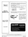
MODEL NO,
'_
358.356090-3.7/20"
358.356100-3.7/18"PS
i
....................
ii
Sears,
66371-1-12084-2-17884
Roebuck
and
Co.,
Chicago,
IlL 60684
U.S,A.
PRINTED IN U. S. A.
FULL ONE YEAR WARRANTY ON GASOLINE CHAIN SAW
(Excluding Bar, Chain, Spark Plug, Air Filter and Starter Rope)
-
For one year from date of purchase, when you maintainl lubricate,'and
tune up this chain saw according
to the operating
and maintenance
instructions in the owner's manual, Sears will repair defects in material or workmanship in this gasoline
chain saw at no charge.
This warranty excJudes
during normal use.
the bar, chain, spark plug, air filter, and starter rope which are expendable
If this chain saw is Used for Commercial or rental purposes, this warranty
SERVICE
parts and become
_:_
worn
applies for only 30 days from date of purchase. WARRANTY
IS AVAILABLE BY RETURNING THE CHAIN SAW TO THE NEAREST SEARS SERVICE CENTER IN THE UNITED STATES.
This warranty
gives you specific
legal rights,
and you may also have other
Sears. Roebuck
TABLE
rights
which
vary from state to state.
and Co.. Sears Tower. Dept. 698/731A.
Chicago,
IL 60684
OF CONTENTS
Specifications ...............................
Safety Rules and Precautions .................
..............................
KnowYourChainSaw
:T:-:: ::-::-: :-::::-:-:-::-_-:--:_
A. Introduction .............................
B. State and Local Ordinances
...............
C. Carton Contents ..........................
Preparing Your SaW For Use .....................
A. Getting Ready
.........
B. Attaching the Hanclguard" : :: ::: ::_! ........
C. Attaching the Spur .......................
D. Attaching the Bar and Chain ................
E. Chain Tension ............................
F. -Engine Fuel Mixture ......................
G, Bar and Chain Oil ........................
Using Your Saw ............................
A. Control Devices .........................
B. Starting Instructions .....................
C. Controlling Kickback .....................
2
Using the Power Sharp® System ..............
12
3
Types of Cutting ............................
14
5 .....................
-A.--BasicCutting-Te-Chriiq-u-e-.-TT:.-:.-:__T-:-_:._-_.-T: -1-4
5
B. Tree Felling Techniques ..................
14
5
C. Bucking ..................................
16
5
D. Debranching and Pruning ............
- .....
17
:6
Maintenance ...............................
18
6
A: Guide Bar and Chain ....................
18
:6
B. Ignition, Cooling, and Exhaust Systems ......
19
6
C. 'Starter Rope Repair and Replacement ......
20
7
D. Clutch .and Drum/Sprocket ................
21
8
E. Carburetor Adjustments ..................
22
8
F. Air Filter ...............................
23
9
G. Counter-Vibe ® Vibration System ...........
23
10
H. Storage ...............................
24
10
I. Maintenance Accessories .................
24
10
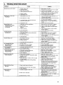
J. Trouble Shooting Chart ...................
25
11
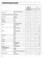
K. Maintenance Chart ......................
26
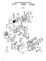
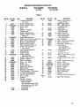
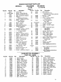
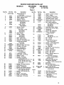
Parts List ..................................
28
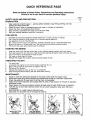
Quick Reference Page .......................
35
SPECIFICATIONS
MODEL
CU_IN. DISPLACEMENT
GUIDE BAR -':LO-KICK
I
'
358.356090 (3.7/20")
3.7 cu. in.160 cu. cm,
_
CHAIN
"
'
.......
=_--_'"
,,r
,.
_
-' :
18" Sprocket
3/8 Extendedr'Pitcli
318 Extended Pitch
Oregon ® Power Sha.rp ®
:
Chrome Cutters-66 Drive Links
Oregon'-*; Xtra*GUARD*Chrome Cutters-7O Drive Links
....
AIR GAP "
,008
.....
OILER S¥STP-M
Spark
'
FUEL TANK CAPACITY
,
Mixture
Arresting Temperature
Automatic
Manual
19oz,
OIL TANK CAPACITY
' "
"
16:1
Limiting
562 cu. cm.
12 oz. 355 cu. cm.
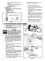
POWER SHARP ADJUSTING
KNOB (MODEL 358.356100)
HANDGUARD
OILER
STARTER HANDLE
/ _ --HANDGUARD
COVER KNOBx
/)_,
THROTTLE
"_'_/'//i_...-'_r_
"
to .014
GasotinelOil
MUFFLER
Nose
" Champion, C J-BY
• ,
,023 tO.027
.
'
Solid State
FUEL MIX
AIRF,
LTE.
358.356100 (3,7118"P.S.),
3.7 cu. inl60 cu, ¢m,
20"SprocketNose
SPARK PLUG
SPARK PLUG GAP
!GNITION
MODULE
.
.
CHAIN TENSION
CHAIN
THROTTLE DETENT
SPUR
SWITCH
LO-KIc' GUIDE
BAR
THROTTLt_ TRIGGER
2
FRO_T CHAIN CATCHER
=
•
OIL
FUEL
. .
'.
P
REAR ;HAIN
CATCHER
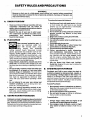
SAFETY
t
A.
RULESAND
PRECAUTIONS
:
WARNING!
:_:
Because a chain saw is a high-speed wood-cutting tool, special safety precautions
must be observed to reduce the risk of personal accidents. Careless or improper use
may cause serious injury.
KNOW
YOUR
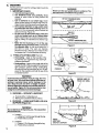
To reduce the hazard of kickback:
SAW
1. Hold the saw firmly with both hands. Left hand
on front handle barl right hand on rear handle
whether you are right-handed or left-handed.
Never use the saw with one hand .......
2. Do not overreach.
3. Do not let the tip of theguide bat contact the
ground, another log, branch, Or any other
obstruction.
1 Read your Owner's Manual carefully until you
completely
understand and can follow all
safety rules and operating instructions before
attempting to operate the unit.
:
. _i
:2. Restrict the use of your saw to adult users
who Understand and follow the safety rules,
....precautions,
and operating
instructions
B.
PLAN
5. Cut one log atatime.
6. Use extreme caution when. re-entering a previous cut.
.7. Donot attempt plunge cuts .....
8. Watch for shifting logs' or other forces that
could close a cut and pinch the chain.
9. DO not cut above shoulder height.
10.
Follow manufacturer's
chain sharpening
and maintenance
instructions.
Keep the
chain properly tensioned. Check tension at regular intervals with the engine stopped, never
,,,
with the engine, running,-Make: Sure the bar
clamp nuts are secure!y:tightened after !ension,, .ingthe chaio..
:.,_
.
11. _Use. the Guard Link. Chain and.. Lo-Kick®
Guide Bar designed foryour saw to reduce the
hazard of kickback.
..........
-
AHEAD
Wear personal protective gear. Atways use steel-toed safety footwear with nomsliP soles
snug.......:
fitting
clothing :with
reinforced
cutting resistant inserts; heavy-duty non'slip
,
gloves; appropriate eye protection such as nonfogging; vented goggles or face screen; an ap: :: proved safety hardhat, and sound barriers I ear
- = . plugs or mufflers to protect your: hearing. Regular
users should have hearing _hecked regularly, as
: "chain saw noisemay damage hearing. '
"
' 2. Keepchildren,
bystanders, and pets out of the
....work area.:Do not allow other people tobe near
::'the chain saw when starting or operating'the chain
saw_:
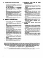
D. AVOID
3. Do not handle or operate a chain saw when you
are fatigued, ill, or upset; or if you havetaken
.i
:alcohol, drugs or medication. You must be in
good physical condition and mentally aiert. Chain
saw work is strenuous. If you have any condition
that might be aggravated by strenuous work,
check with your doctor before operating a chain
saw.
GUARD
AGAINST
KICKBACK
.....
_ .
To avoid Pushback:
,
1. Be extremely aware of situations or obstructions that may cause material to pinch the top of
or otherwise stop the chain.
: 2. Do not cut morethan one log at a time.
3. Do not twist the saw as the bar is withdrawn
_ from an under-cut when bucking.
To avoid Pull-In:
Kickback can lead to dangerous loss of control of
the saw and possiblY cause serious personal injury. Kickback is the upward and backward motion of
the guide bar that occurs when the moving chain contacts an object at the tip of the guide bar.
FORCES
Pushback and Pull-in occur when the chain is
suddenly stopped by being pinched, caught, or
by :contacting a foreign object in thewood. This
results in a reversal of the chain force used to cut
wood and causes the saw to move in the opposite di•rection Of chain rotation, resulting in loss of control
and possible serious personal injury.
4. Do not attempt to use your saw during bad
weather conditions such as strong wind, rain,
snow, etc., or du ring darkness.
5. Plan your sawing operations carefully in advance. DO not start cutting until you have a ctear
' iw0rkarea,
secure footing, and if you are felling
• trees, a planned retreat path.
:
Cw
REACTIVE
•
1. Always begin cutting with the engine at full
throttle and the spike against the wood.
2. Use wedges made of plastic, wood, or light
alloy (never of steel or iron) to hold the cut
open.
E.
HANDLE
FUEL WITH
CAUTION
....
G,
1. Eliminate all sources of sparks or flame in the
areas where fuel is mixed, poured, or stored.
There should be no smoking, open ftames, or work
that could cause sparks:
2. Mix, pour and store fuel in a well-ventilated
area, on bare ground, and in an approved,
marked container.
3. Wipe up all spilled fuel before starting your
YOUR
ORDER
SAW :IN
GOOD
4. Move at least 10 feet (3 meters) away from fuel
and fueling site before starting the engine.
5 Do not smoke while handling fuel or while
operating the saw.
6. Turn the engine off and let your saw cool before removing the fuel tank cap and refueling
the unit.
1. Have all chain saw service performed by your
authorized service dealer center, other than the
items listed in the maintenance section of this
manual.
2. Keep fuel and oil caps, screws and fasteners
securelytightened.
3. Keep the handles dry, clean, and free of oil or
fuel mixture.
4. Make certain the saw chain stops moving
when the throttle trigger is released. If it does
not, refer to page 22 for correctcarburetor idle adjustment instructions.
5. Stop the saw if the chain strikes aforeign object. Inspect the unit and repair or replace parts as
necessary.
OPERATE
7.
saw.
F.
MAINTAIN
WORKING
YOUR
SAW SAFELY
1. Do not operate a chain saw that is damaged,
improperly adjusted, or not completely and
securely assembled.
2. Do not operate the saw from a ladder or in a
•tree,
3. Position all parts of your body away to the side
of the saw chain protrudingto the left of cut when
the engine is running.
4. Cut wood Only. Do not use to pry or shove away
limbs, roots or other objects.
5. Make sure the chain will not make contact before starting the engine. Never try to start the
saw when the guide bar is in a Cut or kerr.
6. Use extreme caution when cutting small size
brush and saplings. Slender materialmay catch
the saw chain and be whipped toward you or pull
you off balance.
7. Be alert for springback when cutting a limb that
is under tension so you will not be struck by the
limb or saw when the tension in the wood fibers is
released.
8. Do not put pressure on the saw at the end of
a cut. This could cause you to lose control when
the cut is completed.
9. Stopthe engine before setting the saw down.
H.
ments.
Never modify your saw in any way. Use Only
attachments supplied or specifically recommended by Sears.
CARRY
SAFELY
AND
YOUR
SAW
1. Hand carry the unit with the engine stopped,
the Muffler away from your body, and the Guide
Bar and Chain to the rear cowered preferably with
a scabbard,
2. Before transporting in anyvehicle or storing in
any enclosure, allow your saw to cool completely, cover the bar and chain and properly secure to avoidturnover, fuel spillage or damage.
3. Drain oil and fuel tank before storing for more
than 30 days.
4. Store in a dry area out of the reach of children
and away from where fuel vapors can reach an
open flame from hot water heaters, furnaces, etc.
Exposure to vibrations through prolonged use of chain saws may produce Whitefinger disease (Raynaud's
phenomenon). This phenomenon reduces the hand's ability to feel and regulate temperature, produces
numbness and burning sensations and may cause nerve and circulation damage and tissue necrosis. An
anti-vibration system designed to reduce engine vibration is available on many Sears models and is
recommended for those using chain saws on a regular or sustained basis.
An anti-vibration system does not guarantee the avoidance of Whitefinger disease, Continual and regular
users should monitor closely their use of chain saws and physical condition.
4
KNOW
A.
YOUR CHAIN
SAW
B.
INTRODUCTION
STATE
AND LOCAL
REQUIREMENTS
The information found in this manual will help
you properly prepare your chain saw for use,
understand how to operate your saw safely, and
perform maintenance required to keep your unit
ingo0d working condition.
Your saw has beendesigned
and includes the following
standard equipment:
Your saw is equipped with a temperature
limiting muffler and spark arresting screen
which meets the requirements
of California
Codes 4442 and 4443. All U.S. forest land and the
states of California,
Maine, Washington
and
Oregon
require
many internal
combustion
engines to be equipped with a spark arrestor
screen and a temperature
limiting muffler by
law.
if you operate a chain saw in a state or locale
where-such-regulationsexist;youarelegallyre;
sponsible for maintaining the operating condition of these parts;Failure to do so could subject
you to liability or to a fine. Muffler and spark arrestor maintenance is found on page 19.
with safety in mind
safety features as
Spark Arrestor
...................................
Handguards
Counter-Vibe ®Vibration System
Lo-Kick® Guide Bar
Guard Link Chain
The chain saw should never be operated unless
these devices are properly installed on the unit.
The Lo-Kick® Guide Bar and Guard Link Chain have
......
:been designed to reduce the hazard of kickback. You
should thoroughly read and understand the section,
"Controlling Kickback"on page 11.
ORDINANCE
CARTON
Cm
CONTENTS
After you unpack the carton:
1. Check the contents against the list below.
2. Examine the items for damage.
3. Notify your Sears Store immediately
if a part
is missing or damaged ....
KEY NO. CARTON
1
2
3
CONTENTS:
Power Head
Guide Bar
8 oz. can, 2-Cycle Engine Oil
Loose Parts Bag (not shown)
QTY.
1
1
1
1
LOOSE PARTS BAG coNTENTS:
m
4
5
6
7
8
9
10
H
Operator's Manual (not shown)
Handguard
Cap-Handguard
Screws-Handguard
Spur
Screw-Spur
Chain
Scrench
1
1
1
3
1
2
1
1
-
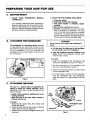
PREPARING
A.
GEEING
YOUR SAW FOR USE
READY
1. READ
YOUR
0PERATOWS
MANUAL
2. HAVE THE FOLLOWING
CAREFULLY'" .....
a. Protective gloves
_-..... '
b; Approved, marked fuel container
c. One gallon leaded or unleaded, regular
gasoline
•
•
:
_ :_'
d. Bar and Chain Lubricant (see page 9).
e. Scrench--provided with your unit. No other
. tool is necessary for assembly. The long
end of the too! can be used as a slotted
screwdriver. The small PiPe end canbe us-
._
......Your Operators; Manual has been developed to
i _ help you,prepare your saw for use and to under• Stand its safe operation. It is;important that you
read your manual completely to become familiar
with the unitbeforeyou begin assembly.
•
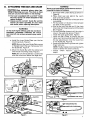
B.
ATTACHINGTHE
,
,, H,,
HANDGUARD
The Handguard is a protective device designed
to hetp prevent your hand from coming in contact with the cutting chain should your hand slip
off the handlebar,
tt will not:eliminate
the
possibility
of injury from kickback or toss of con_trol of.the saw.
.........
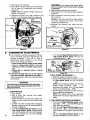
CAP
HANDGUARD
AVAILABLE:
HANDLE
WARNING!
.......
Do not use the saw without the handguard in
place.
,
•
Lift and carry the chain saw by the handlebar
or rear handle, not by the handguard.
• Keep the handguard securely fastened at all
times. Check the handguard screws each
time the saw is used. ....
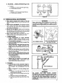
To install:
1. Alignthe
Handguard and Handguard Cap
around the handlebar as shownin
Figure 1.
2. Fit the imounting pin on the Handguard
the hole in the handlebar. Figure 1.
3. Insert the 3 mounting screws
on the Handguard Cap.
.... : :i:" ::-iFigure 1 :_
C.
ATTACHING
THE
?_ _
into the 3 holes
4. Turn .each screw a little at a time clockwise,
until the Handguard
Cap and Handguard
meet and there is no gap between the two
parts.
SPUR
i,,i
The spur is a special piece,of
equipment designed to assist the cutting operation. When
assembled to the saw, the spur. will dig into the
tree or log and:
_i ....
--relieve contact pressure adding"ease to the
sawing operation.
--allow the saw to be more easily rotated or
pivoted into the cut.
To Install:
1. Remove Bar Clamp Nuts, Bar Clamp and
Guide Bar Plates.
2. Align the spur over the two holes on the bar
clamp side of the saw. Figure 2.
3. Insert the two screws and tighten evenly and
securely.
into
BAR
CLAMP.
(
GUIDE BAR PLATES
BAR NUTS
Figure 2
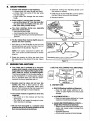
D.
ATTACHING
THE
BAR
AND
WARNING!
CHAIN
_ICAUTION:!Wear
protective gloves when han.
dling or operating your saw. The chain is sharp
and can cut you even when it isnot moving!
• Your saw is equipped with a Lo-Kick ® Guide
Bar and a Guard Link Chain designed to help
reduce kickback.
• Always use the Lo-Kick _ Guide Bar and the
Guard Link Chain specified for your chain
saw model, when replacing these parts.
/
!'
Never try to install the bar upside down to avoid increasing the hazard of kickback.
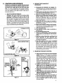
c. Hold chain with cutters facing as shown in
Figure 6.
d. Place chain over and behind the clutch
drum onto the sprocket,
e. Slide Guide Bar to the rear of the saw as far
as possible.
f, Fit the bottom of the drive links between
the teeth in the sprocket.
g. Start at the top of the bar and fit the chain
drive links into the groove around the Guide
WARNING_
Bar. Figure 6.
'
Do not start engine without guide bar and chain
I
h. Pull the Guide Bar forward until the chain is
completely assembled. Otherwise
the clutch
I
snug in the guide bar groove Figure 7.
can come off and serious personal injury could
/
i Install the outer guide plate "Figure3
..................................
result: .............
................
:.................................................................
:...........................................................................................
J_.....................................................
by.__J_i
d_Lng....t.h'e_
bar .....................
clamp over the mounting studs arid fitting
a. Install the Inner:Guide
Plate over the bar
.the baradjusting
pin into the round.hole
in the Guide Bar. Figure 8.
....... mounting studs. Figure 3,
k. Replace the Bar Mounting Nuts and tighten
NOTE: Be sure the Inner Guide Plate curves
finger tight only.
or flanges toward the saw frame away from
NOTE: The Bar Clamp nuts must be slightly
the Guide Bar. Figure 4.
loose to tension the chain correctly,
b. Mount the Guide Bar with the slotted end
I, Follow
"Chain
Tension,
•instructions,
over the bar mounting studs. Figure 5.
page 8.
NOTE: Be sure the Guide Bar is positioned
with the round hole below the large slot.
INNER
PLATE
GUIDE
Figure 3
Figure 4
:-;1
Figure 6
c u'c"
1
,
ADJUSTING
Figure 7
BAR ADJUSTING
6
Figure 5
PIN HOLE
PIN
6
Figure 8
7
E.
CHAIN
•
TENSION
COrrect chain tension is very important:
--a loose chain will wear the bar and itself,
--a loose chain can jump off the bar while
you are cutting.
--a tight chain can damage the saw and/or
break,
3. Continue turning the Adjusting Screw until
the tension is correct.
_ .
4, Hold the tip of the Guide Bar up and tighten
the Bar Clamp Nuts with the Scrench.
5, Recheck tension.
• Chain tension is correct when the chain:
--can be lifted about 1/8" from the Guide Bar
at a point near the middle of the bar, and
•--will move freely around the bar.
TURN
TO LOOSEN
TENSION
• The chain stretches during use, especially
when new. Check tension:
:-- each time the saw is used
w more frequently when the chain is new
J as the chain warms up to normal operating temperature
• The Bar Clamp Nuts must be slightly loose to
tension the chain correctly.
1. Hold the tip of the Guide Bar up and turn the
Adjusting
Screw. just until the,chain does not
sag beneath the Guide Bar, Figureg.
TURN
TO TIGHTEN
TENSION
Figure 9
CHAIN CAN BE
LIFTED 1/8"" WHEN
TENSION IS
CORRECT.
'NOTE:
Turn screw clockwise to tighten tension; Turn screw counterclockwise
to loosen
tension .....
o
2. Check the tension by lifting the chain from
the Guide Bar at the center of the bar. Figure
i0.
'
Figure 10
U'XTURE:
F'
•
......
:
Your chain saw is powered by a two-cycle
engine which requres a fuel mixture of regu_lar gasoline anda high quality engine oil specially made for 2-cycle, air-cooled engines.
The internal design of the 2-cycle engine requires lubrication of moving parts. Lubrication is provided when you use the recommended mixtureof
gasoline and oil,
.
• Gasoline must be i clean and not over two
months old. After :a sl_ort period of itime,
gasoline ,begins to chemically 'break down
and will form compounds that can cause hard
starting and damage in 2-cycle engines.
;
:
• The correct measure of gasoline to oil is very
important.
:_ --Too much oil in the mixture will =fou! the
........
Spark plug.
........... --Too little oil will cause the engine to overheat resulting in damage,
• Mix the fuel thoroughly in a container since
gasoline and oil do not readilycombine. Do not
try to mix fuel directly in the fuel tank.
1. USE THE
FOLLOWING
FUEL MIXTURES:
2. DO NOT USE:
• BIA Oil (Boating Institute of America)
--Does
not have proper additives for aircooled, 2-cycle engines and could cause
damage.
• AUTOMOTIVE
-
OIL-
Does not have proper additives for 2-cycle
engines and could cause damage.
• GASOLINE CONTAINING ALCOHOL(High Test, Premium or Gasohol)
Stiffens critical carburetor fuel metering elements and causes engine damage from
overheating.
Increases vaporlock.
m Attracts water causing corrosiondamage.
3. HOW
4. IMPORTANT
TO MIX FUEL
a. Pour one-half of the gasoline into an approved, marked container. Do not try to mix
oil and gasoline directly in the fue! tank.
b. Add entire measure of 2*cycle Engine Oil.
c. Mix.
d. Add remainder
of gasoline.
e. Mix thoroughly
for one minute.
POINTS
ao Eliminate all sources of sparks or flame in
the areas where fuel is mixed, poured, or
stored. There should be no smoking, open
flames or work that could cause sparks.
b. Mix, pour and store fuel in an approved,
marked, container and in a well-ventilated
area. Gasoline vapors are harmful to your
health and are a serious fire hazard. Use a funnel or spout when pouring fuel.
c. Avoid overfilling the fuel tank. Allow3/4 inch
for ex pansion. Tighten Fuel Cap securely. Figure 11.
d. Wipe up all fuel spills. Wipe off any fuel spilled on the saw. Completely dry the saw before
using.
e. Move at least 10 feet (3 meters) away from
fueland fueling site before starUng the engine.
Figure 11
G.
BAR
AND
CHAIN
OIL
• The guide bar and cutting chain require con.
tinuous lubrication
in order to remain in
operating condition.
Lubrication is provided
by the automatic
oiler system when the oil
tank is kept filled,
--Lack of oil will quickly ruin the bar and
chain.
--Too little oil will cause overheating shown
by smoke coming from the chain and/or
discoloration
of the guide bar rails.
• Use Sears Bar and Chain Lubricant #71-36554
or clean SAE 30W oil.
In freezing weather oil will thicken, making it
necessary to thin bar and chain oil with a
small amount of Diesel Fuel #1 or Kerosene.
Bar and chain oil must be free flowing for the
oil system to pump enough oil .for adequate
lubrication.
FILLTHE
TANK EACH
THE FUEL TANK
IS FILLED
1. USE THE
FOLLOWING:
30°F or above
Lubricant
30°F - 0° F --
95% lubricant to 5% Diesel
Fuel #1 or Kerosene.
Below 0°F
90% lubricant to 10%
Diesel Fuel #1 or Kerosene.
2. HOW
TO FILL THE
-- undiluted.
OIL TANK
a. Stop the engine.
b. Turn saw on its side with oil cap up. Figure
12.
c. Loosen cap slowly and wait for pressure in
the tank to be released before removing the
cap.
d. Fill the oil tank.
e. Replace the oil cap securely.
3. IMPORTANT
POINTS
TO REMEMBER
a. Fill the oil tank each time you refill the fuel
tank to ensure there wilt be sufficient oi! for
the chain whenever you start and run the
saw.
b.
C.
Figure 12
The saw will use about 112 tank of chain oil
for each tank of fuel mixture. If tess oil is
used, check for a plugged oil hole in the
guide bar.
;
•
It is normal for a small amount of oil to appear under the saw after the engine stops.
This is due to oil draining from the bar and
chain when not in use.
9
USING
A.
YOUR
CONTROL
SAW
.... i
i
DEVICES
THROTTLE
DETENT
BUTTON
Understanding
the control devices on your saw
is an important part of learning how to properly
and safely operate the unit. Figure 13. _
1: The ignition Switch is a!oggte
switch which
is moved up for the "Start" position and moved down for the' "Stop" i_osition.
2. The two-position
Choke helps to start the
saw by controlling
the air flow to the fuel
system.
3. The Trigger accelerates
and controls
the
speed of the engine and is designed to be
used with the Throttle Lock.
bKE
STARTING
1. IMPORTANT
HALF
your right thumb. Use the manual oiler to SUpplemeht
the automatic Oiler:
--during a long felling cut
--when cutting into a tog or tree which is
greater in diameter than the tength0f
the
guide bar.
_--anytime an additional supply of oil is desired.
WARNING_
-Always wear gloves; safety footwear; snugfitting clothing; and appropriate eye, hearing,
and head protection devices when operating a
chain saw.
a. Push down onthe throttle lockout, squeeze
the trigger, press and hold down the throttle detent button, then slowly release the
trigger.
b. Engage choke according to "Starting Instructions" below.
c. Hold saw firmly with the saw chain free to
turn without contacting any object. Figure
14.
d. Pull starter rope quickly, using no more
than 15-18 inches of rope per pull. Using the
full length of the starter,rope may cause it to
break, Do not let the starter rope snap back.
Hold the handle and let the rope rewindslowly.
e. Release the throttle detent button after engine starts, allowing the engine to idle. The
chain must not move when the engine runs at
idle speed, if correction is required_' refer to
CarburetorAdjustments,
page 22.
f. Stop engine by moving the ignition switch
to the "STOP" position (Figure 13).:
TO START
-- HOLD FRONT HANDLEBAR AND PLACE RIGHT
FOOT THROUGH HANDLE.
Figure 14
WARNING.!
Avoid bodily contact with the muffler when starting
a warm engine. The muffler can become very hot
and can cause serious burns.
P.# chokeknob Prezs throttle
MM ign_.
,wMcbtDstilrt
t01ullctmke
I_k =nd
x:
x
X:
x
c,okeo,
x
x
x
cho,e
o,
x
tdgger
squu_
X
×
x
Press thmlge
Pui_ruder rope I_sh _oke kilOb PtlITstarterrope
detent bMton
r_asa bigger
X
untU sngLnefires
in
UL_Ier_ns ruIts
3-5 times
X
X
X
3-5 times
X
x
x
_ t_m=s ,a_c,oke"
Squeeze t_gger
_
___
* Allow engine to warm-up thoroughly on half-choke,
choke at the "On" or "Half" position. Figure 13.
10
OFF
STARTtSTO
SWITCH
TRIGGER
POINTS
a. Cold Engine
.... b. Warm Engine
• C; Refueled:Engine
after running
out of gas
d. Flooded Engine
e. Cold Weather starting
STARTtSTOP
SWITCH
OILER
INSTRUCTIONS
2. STARTING PROCEDURE
:
ROTTLE
LOCKOUT
prevents the Trigger from becoming accidently engaged. The Throttle Lock must be pressed before the Trigger can be activated.
5;The Throttle Detent Button holds the Throttle
Lock and Trigger in position while the engine
is being started. Release the Throttle Detent
Button after the engine is started by lightly
squeezing the trigger.
B.
START
then move choke to the "Off"
to relOllSe
detent
X
%2 times
X
X
X
x
x
x
x
{out of cut)
position. Do not cut with the
_.
C.
CONTROLLING
KICKBACK
........
Kickback isa dangerous reaction thatcancause
serious personal injury. Carefully study this manual before you make the first cut with your new
saw. "Youmust understand what causes kickback,
.how you can reduce the chance of kickback, and how
:you can remain in the best control of the saw if
kickback does occur.
1. _WHAT CAUSES
KICKBACK
:
Kickback can occur when the moving chain
- __ contacts an object at the tip or nose of the
guide bar. This contact causes the chain to dig
_-_.
into the object and stops the chain for an instant.
The
result is a lightning fast, reverse reaction
which kicks the saw tip up and back toward the
operator. The operator can lose control of the saw
and the cutting chain can cause serious personal
injury if it contacts any part of the body.
Figure 15
AVOID OBSTRUCTIONS
2.
REDUCETHE
KICKBACK
AREA
Figure 16
;
THUMB
ON _
UNDERSIDE
NEVER
_EVERSE
b
RM
,_/,
OAFRANDLE_ _,Y,_#j
STRAIGHT
Figure 17
.....................
OF
:
:,:
a. Recognize that kickback can happen. By
understanding and knowing about kickback,
you are better equipped to deal with an occurrence.
b. Never let the moving chain contact any object at the tip of the guide bar. Figure 15.
c. Keep the working area free from obstructions such as other trees, branches, rocks,
fences, stumps, etc. Figure 16. Eliminate or
avoid any obstruction that your saw chain
could hit while you are cutting through a particular log or branch.
d. Keep your saw chain sharp and properly
tensioned. A loose or dull chain can increase
the chance of kickbackl
e. Begin and continue cutting at full throttle.
If the chain is moving_ataslower-speedTthere ........................!
is greater chance for kickback to occur.
f. Cut one log at a time.
g. Use extreme caution when re-entering a
previous cut.
h. Do not attempt plunge cuts.
i. Watch for shifting logs or other forces that
could close a cut and pinch or fall into the
chain.
j. Use the Lo-Kick_Guide Bar and Guard Link
Chain specified for your particular saw.
These devices have.been_designed to reduce
the hazard of kickback:
""
k. Use extra caution if your saw is equipped
with the Power Sharp-" System. The Power
Sharp '_saw is equipped with a Lo-Kick =.Guide
Bar and a Guard Link Chain. However, due to
the chain requirements of the built-in sharpen.ing mechanism, the kickback force from the
Power Sharp'" chain may be greater than that
from other Guard Link chains.
3. MAINTAIN
CLEAR WORKING
CHANCE
THE BEST CONTROL
a. Keep a good firm grip on the saw with both
hands. Figure 117.A firm grip can neutralize
kickback and help you maintain control of the
saw. Keep the fingers of your left hand encircling and your left thumb under the front handlebar. Keep your right hand completely
around the rear handle whether you are right
:handed or/eft handed. Keep your left arm
straight with the elbow locked.
b. Position your left hand on the front handlebar so it is in a straight line with your
right hand on the rear handle. Figure 17.
Never reverse rightand left hand position.
c. Stand with your weight evenly balanced on
both feet.
d. Stand slightly to the left side of the saw, to
keep your body from being in a direct line
with the cutting chain; Figure 17.
e. Do not overreach. You could be drawn or
thrown off batance and lose controlof the saw.
f. Do not cut above shoulder height. It is difficult to maintain control of the saw above
shoulder height.
11
USING THE POWER
,
, ,
,
SHARP®SYSTEM
,,
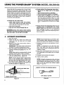
• Model 358.356100 is equipped with a Power Sharp ®
:System that will perform approximately 80% of the
sharpening necessary for the saw chain. The Power
Sharp® System uses a built-in grinding stone to sharpen the cutter top plates and set depth gauges. As
: the built-in sharpener is used, the cutter side plates
.gradually
will be altered. Hand filing is required to
correct the cutter side plates.
• Sharpen the saw chain when:
--wood chips become small and powdery.
Wood chips made by the chain should be
about the size of the teeth of the chain.
--saw
has to be forced through the cut.
JCAUTION:J ALways wear gloves when handling
the chain. The chain can be sharp enough to cut
you, even when it is too dull to cut wood.
A,
AUTOMATIC
:
'IMPORTANT: The chain must be tensioned
correctly for proper sharpening to occur.
4. Start the engine and operate at half to three/
quarters throttle during steps "5", "6", "7",
and "8".
NOTE: Saw must be running at half to three/
quarters throttle before knob is pressed.
_: 5:Push the Power Sharp ® i Kn0bdown slowly
: Untit fully pressed down. Figure19.
NOTE:If stone should contact chain before
knob is fully pressed down, release knob
and turn knob counterclockwise until condition does not exist. Repeat :Step "5" again.
6. Turn knob slowly clockwise until sparks can
be seen as shown in Figure 19.
SPARKS ARE SEEN HERE
POWER SHARP®KNOB
i
12
• Always replace the sharpening stone when
--sparks are no longer seen at full adjust.
ment
--only 1/4 inch of stone is remaining
--stone hasbecome cracked or damaged.
--a new chain is installed. The used stone
wilt be worn to the shape of::the old chain
and can cause excessive wear to a new
chain. Replacement
chain comessupplied
with Stone Cartridge Replacement #69099.
Refer to replacement
instructions
on page
13.
ventional chain is substituted for the Power
Sharp'_. Chain. _See instructions for removing the
Stone Cartridge on page 13. Use replacement
chain #71-3638. Follow chain sharpening instructions on page 18.
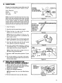
SHARPENING
1. Stop the engine:
2. Place the saw 'on a solid, flat surface and
make sure that the chain will not contact
any object.
3. Adjust the chain with correct tension. Refer to
Chain Tension page8.
....
(MODEL 358.356100)
Figure i9
NOTE: Pro per sharPePing occurs when a light
flow of sparks is seen: Im proper sharpening is
shown by a heavy flowof sparks or no sparks.
7. Release knob and turn one additional
clockwise.
"click"
NOTE: It is important to turn the knob only
one "click" each time the knob is pressed.
More turnswilt result in making the chain dull
instead of sharp.
8. Press knob firmly against chain and hold for
10-15 seconds or until sparks can no longer
be seen.
9.. Reteaseknoband
stop the engine.
10. Inspect chaincutters.
NOTE: A properly sharpened cutter will show
grinding marks across its entire width. Figure
20. If cutters do not appear sharp or burrs are
seen on the top front of the cutters, repeat
Steps "7" and "8".
: INSPECT CUTTERS FOR GRINDING MARKS
TOP VIEW OF CUTTER
Figure 20
B.
HAND
FILING
Sharpen the side ptates by hand after every 3rd
to 5th time the Power Sharp® System is used.
items Required:
Gloves
5/32" file
file holder
FLAT SIDE
"
OF FILE HOLDER
_'_,k-.,_
flat file
vise
PLATE
2. Adjust the chain fo r proper tension ,page 8.
3. Clamp the bar in a vise to-hold
steady. Do not clamp the,chain.
_AUGE
SIDE PLATE
Figure 21
HOLD FILE
HOLDER LEVEL
22 °
WITH THE 22°
GUIDE MARK
PARALLEL TO.
GUIDE BAR
.: 1. Stop the engine.
the chain
Figure 22
NOTE:Work.at
the midpoint of the bar, mov. ingTthe chain forward with a screwdriver
as
each cutter is filed,:.
r
4, Support the square rod on the file holder (with
5/32" round file)on cutter top plate. Figure 21.
5. Hold the file holder level with the 22 ° guide
• mark parallel to guide bar. Figure 22.
- 6. File from inside toward outside of cutter in
one direction only -- 2 or 3 strokes per side
plate edge should be enough. Figure 23.
Figure 23
SIDE
PLATE
SIDE PLATE
li
NOTE: Avoid hitting the top edge of the cutters when filing the side plate.
•
7. Maintain a 1132" side plate projection.
24.
_
....
C.
,
:
1132"
MAXIMUM
Figure
File all side plates on one side of the chain,
then move to the other side of bar and file remaining side plates.
REPLACE
OR REMOVE
STONE
ANDCARRIER
DEPTH
ON TOP OF CUTTER Topic
NOTE: If abrasive materials such as rocks, nails,
sand or dirt are contacted by the chain, the side
plates should be checked more often. Damage
to the cutters
caused by. abrasive materials
usually results in discoloration, spots where the
chrome has been worn away. Cutter side plates
should be filed until these spots are removed.
.
ND FILE
TOP /
PLATE /
I_- 22o
TOP VIEW PROJECTION_
OF CUTTER
I
Figure 24
....
.....
THE
ASSEMBLY
Remove Carburetor Cover and Bar Clamp.
2. Remove the; two:screws which hold cartridge
assembly to crankcase. Figure 25.
3 Discard old assembly.
4. Install new cartridge assembly.
1.
NOTE: Be careful
fall out.
:5. Reinstall
Carburetor
STONE .....
CARTRIDGE
ASSEMBLY
not to tet the Slide Button
Cover and Bar Clamp.
13
TYPES
Ae
BASIC
OF CUTTING
CUTTING
.....
TECHNIQUE
To avoid Pull-in:
1. IMPORTANT
POINTS.
•a. Cut wood only. Do not cut metal, plastics,
masonry, non-wood, building materials;etc.
b. Stop the saw if the chain strikes a foreign
object. Inspect the unit and repair or replace
parts as necessary.
c. Keep the chain out of dirt and sand. Even a
small amount of dirt will quickly dull a_Chain and
thus, increase the possibility of kickback.
a. Always begin cutting with the engine at full
throttle and the spike against the wood.
b: Use wedges made of plastic, wood, or light
alloy (never of steel or iron) to hold the cut
open.
m
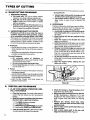
PROCEDURE
Practice cutting a few smalt logs using the following technique to get the '_eel" of using your saw
before you begin a major sawing operation.
2. UNDERSTAND
REACTIVE FORCES
a. Accelerate the engine to full throttle just bePushback and Pull-in occur when the chain is
fore entering the cut by squeezing the ThrottleTrigger.
suddenly stopped by being pinched, caught,
...........................................
o.r..by.#ontactinga, fore!gn.obje_ in_the_wood__...........................
),....Begin cutting with the spur against the log.
This results in a reversal of the chain force used
Figure 26,
c. Keep the engine at full throttle the entire
to cut wood and causes the saw to move in the optime you are cutting.
posite direction of chain rotation, resulting in loss
d. Allow the chain to Cut foryou; exert only light
of control and possible serious personal injury.:'.
downward pressure. If you force the cut, dam'e Pushback:
age to the bar, chain or eng_ne can result.
--occurs when the chain on top of the bar, is sude. Release the throttle trigger as soon as the
deftly stopped When the top of the bar is used for
cut is completed, allowing the engine to idle.
cutting.
If you run the saw at full throttle without a cut.... drives the saw straigl_t back toward the operator,
ting load, unnecessary wear can occur to the
poss!bly causingloss of saw control.
chain, bar, and engine.
To avoid Pushback:
f. Do not put pressure oh the saw at the end
a. Be extremely
aware of situations or
of the cut to avoid Iosing control when the cut
obstructions that may cause material to stop
iscomplete.
or pinch the top of the chain.
g. Stop the engine before setting the saw
....b. Do not cut more than one log at a time.
down after cutting.
c. Do not twist the saw as the bar is withdrawn
="
from an under-cut_
e Pull-in:
R occurs when the chain on the bottom of the bar
is suddenly stopped.
-- occurs when the spike orsaw housing is not held
securely against the tree or limb and/or when the
cut is not begun at full throttle.
-'pu!!s
the. saw forward, :and could cause the ==
operator to lose control.
BEGIN CUTTING WITH THE
PUR AGAINST LOG.
Figure 26
=•
B.
TREE
.
FELLING
TECHNIQUES
PLAN YOUR SAWING
FULLY IN ADVANCE
OPERATION
....
CARE-
a. Clear the work area. You needa clear area all
around the tree where you can have:secure
footing.
•
'=: _
b. Studythe natural conditions that can cause
thetree to fall in a particular direction:
1 :) The WIND direction and speed
2.) The LEAN of thetree :
3.) WEIGHTED with BRANCHESon one side
4.) Surrounding TREES and OBSTACLES
c. Look for decay and r0t. If the trunk is rotted,
itcould snap and fall toward the operator.
14
•:
d. Check for broken or dead branches which
Could fall on you while cutting.
e: Make sure there is enough room for the tree
to fall. Maintaining a distance of 21/2 tree
lengths from the nearest person or other objects. Engine noise may drown out warning
carl.
f. Remove dirt, stones, loose bark, nails,
staples, and wire from the tree =where cuts
are to be made.
g. Plan to stand on the up-hill side when cutting on a slope.
h. Plan a clear retreat path to the rear and
diagonal to the line of fall. Figure27.
2. FELLING
SMALL TREES -- LESS THAN
6" IN DIAMETER
a. If you knowthe direction offall:
1.) Make a single felling cut on the side away
from the direction of fall.
2.) Cut all the way through.
3.) Stop the saw, put it down, and get away
quickly on your planned retreat path.
b.
If you are not sure which way the tree will fall,
use the notch method described for felling
large trees.
/
DIRECTION
-- 4_llmllllllmll
OF FALL
........
_
-_--_
4,_
Figure 28
Figure 27
WARNING!
DO NOT CUT:
near electrical wires or buildings.
if you do not know the direction of tree fall.
at night since you will not be able to see well.
wduring
bad weather m strong wind, snow, rain,
....etc.
_--
t
t
__
DIRECTION
DIRECTION
OF FALL
OPENING OF
FELLING CUT
NOTCH
3.
\
FELLING LARGE TREES m 6" DIAMETER
OR MORE
The notch method is used to cut large trees. A
notch is cut on the side of the tree in the desired
direction of fall. After a felling cut is made on the
opposite side of the tree, the tree will tend to fall
into the notch.
NOTE: If the tree has large buttress roots, removebefore making the notch. Cut into the buttresses vertically, then horizontally, Figure28.
a. Makethe notch cut. Figure29.
1.) Cut the bottom of the notch first, through
1/3 of the diameter of the tree.
2.) Complete the notch by making the slant
cut.
3.) Remove the notch of wood.
b. Make thefelling cut on the opposite sideofthe
notch about 2" higher than the bottom of the
notch.
c. Leave enough uncut wood between the felling
cut and the notch to form a hinge. Figure 30.
NOTE: The hinge helps to keel5 the tree from
twisting and falling in the wrong direction.
d. Use a wedge if there is any chance that the tree
will not fall in the desired direction.
DON'T
PUT YOURSELF
HINGE HOLDS THE TREE ON STUMP
AND CONTROLSTHE
FALL
Figure 29
cut down wind.
Figure 30
NOTE: Before the felling cut is complete, drive
wedges to open up the cut when necessary to
control the direction of fall. Use wood, plastic or
light alloy wedges but never steel or iron, to
avoid kickback and chain damage.
e. Be alert for signs that the tree is ready to fall:
1.) cracking sounds
2.) widening of the felling cut
3.) movement in the upper branches.
f. As the tree starts to fall; stop the saw; put it
down, and get away quickly on yourplanned
retreat path.
g. Be extremely cautious with partially fallen trees
that may be poody supported. When a tree
doesn't falllcomp!etely, set the saw aside and
, pul!down the tree with acable winch,block and
tackle or tractor. Do not cut it down with your saw
to avoid injury.
IN THESE
/
Don't
CLOSING
Don't cut on lean side.
POSITIONS
Check the l)ai_ance.
Don't cut on weighted side.
!5
C.
BUCKING
Bucking is the term used for.cutting a fallen tree to the
WARNING!
desired log size.
Never turn the sawupside down to undercut, The
1. IMPORTANT POINTS
saw cannot be controlled in this position.
a. Cut only one log at a time.
b. Cut shattered wood very carefuilyl Sharp
pieces of wood could be flung toward the
1ST CUT PRESSU RE SIDE
operator.
..--_
c. Use a sawhorse to cut small logs. Never
allow another person to hold the log while cutting and never hold the log with your leg or foot.
d. Give special attention to logs under strain
to prevent the saw from pinching. Make the
first cut On the compression side to relieve the
stress on the log. (Figure 31)
2ND CUT
e. Do not cut in an area where logs, limbs and
roots are tangled such as in a blown down
area. Drag the logs intoa clear area before cutting by pulling out exposed and cleared togs
....................................................
7................................
first: ............................................................................................
_.................................................
f."_Make the first bucking cut 1/3 of the way
.
through the log and finish with a 2/3 cut on
Figure 31
_
......
the opposite side. As the log is being cut, it
will tend to bend. The saw can become
.... ' pinched or hung in the log if you make the first
cut deeper than 1/3 of the diameter of the log.
2. TYPES OF CUTTING USED Figure 32.
-- Overcutting - begin on the top side of the
log with the spur against the log: exert light
pressure downward.
m Undercutting - begin on the under side of the
log with the top of the saw against the log; exert
light pressure upward. During undercutting,
the saw will tend to push back at you. Be prepared for this reaction and hold the saw firmly
to maintain control.
UNDERCUT
OVERCUT
Figure32
WARNING!
If saw becomes pinched or hungin a log, don't try
to force it out. You could lose control of the saw resulting in personal injury and/or damage to the
saw. Stop the saw and driveawedge
ofplastic,
wood orlight alloy into the cut until'saw can be removed easily. Figure 33. Do not use a Steel or iron
wedge to avoid kickback and chain damage,
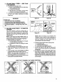
3. BUCKING--WITHOUT
WEDGE USED TO
HOLD CUT OPEN
/
A SUPPORT
a. Overcut with a 1/3 diameter cut.
b. Roll log over and finish with an ovemut.
.
BUCKING
SUPPORT
-- USING ANOTHER
(Figure 34):
LOG AS A
Figure 33
WARNING!
Do not stand on the log being cut. The cut portion
will roll down hill.
a. In areaA:
1.) Undercut 1/3 of the way through the log.
2.) Finish With an overcut.
b. In area B:
1.) Overcut, 1/3 of the waythrough the log.
2.) Finish with an undercut.
16
ANOTHER
LOG AS A SUPPORT
- - .'_:?--__
" _
Figure 34
i
/
5. BUCKING
a.
b÷
w USING A STAND (Figure 35):
In areaA:
1.) Undercut 1/3 of the way through the log.
2.) Finish with an overcut.
In area B:
1.) Overcut 1/3 of theway through the log.
2,) Finish with an undercut.
2ND CUT
CUT
1ST CUT
CUT
2ND CUT
FIRST
CUT
Figure 35
D.
DEBRANCHING
ANDPRUNING
II,:.i:
WARNING!
• Work slowly, keeping both hands on the saw
=with a firm grip. Maintain secure footing and balNever climb int0a tree to debranch or prune_ Do
ance,
not stand on ladders, platforms, a log or inany
• Watch out for springpoles. Use extreme caution
positionwhich might cause you to Jose control of
...........................................
.=when-cutting-smalt-size-timbs:--SlendeF_materiat
.......................
.....
the-saw; ......................................................................................................
_-"_.................................
may catch the saw chain andbe whipped toward
'
- you or,pult you off balance.
' ,
eBe
alert for sPringback. Watch.out for branches
that are bent or under pressure as youare cutting
to avoid being struck by the branch or the saw when
the tension in the wood fibers is released,
• Keep a clear work area. Frequently clear branches out of the way to avoid tripping over them.
1. DEBRANCHING
Limit debranching
to limbs shoulder
height or below. Always debranch a tree
,
'after it isCut down. Only then can debranching
bedone safely and properly.
USE COMMONSENSE_ :
b. Leave the larger lower limbs to support the
_
:tree asyou work:
c. Start at the base of the felled tree and work
.....
Remove smaii limbs
towards the top,_ cutting branches and
with one cut,.
, . _ . :limbs. Remove small timbswith one cut. Fig=
ure36.
d. Keep the tree between you and the chain.
Cut _from .the side of the tree opposite the
branch you are cutting.
,=
eo Remove larger, supporting branches with
the1!3, 2/3 cutting techniques described in
Figure36
.... the bucking section.
= =
...... 1.) Start with an overcut
2,) Finish with an overcut
THIRD
f. Always =use an overcut to cut small and
PRUNINGCUT
freely hanging limbs. Undercutting could
....
cause imbs to fall and pinc h the saw.
IJl SECONO
PRUNING
CUT
2. PRUNING
" a. Limit pruning to limbs shoulder height or
:....
below. Do not cut if branches are higher than
your shoulder. Get a professional to do the
ijob_ :
b. Refer to Figure 37 for the pruning technique.
_:
1,) Undercut 1/3 of the waythrough the limb
: near the trunk ofthe tree.
2.) Finish with an 0vercut farther Outfrom the
'
trunk.
::
_ .... '_:
3.) Keep out of the way of the fall!ng limb.
4.) Cut thestump flush near the trunk of the
tree.
' ' :: ' ": ....
:• v
::!
.
:.
-
FIRST PRUNING CUT
Figure 37
WARNING!
BE ALERT
FOR AND
GUARD
AGAINST
KICKBACK. Do not allow the moving chain to contact any other branches or objects atthe nose of
the guide bar, when debranching or,pruning. Allowing such contact could result in serious personal injury.
..........................
17
H
L¸:
_
:
.
,
MAINTENANCE
• Check the saw for loose bolts, screws, nuts,
and fittings on a regular basis. Loose fasteners can cause an unsafe condition as well as
damage to your saw.
A good maintenance program of regular inspection and care will increase the service life and help
to maintain the safety and performance of your
saw.
• Make all adjustments or repairs (except carburetor adjustments) with:
spark plug wire disconnected
engine cool as opposed to a unit that has
just been run.
GUIDE
BAR
AND
IncreaSe the service
All chain saw service, repair, adjustments and
maintenance not described in this manual should
WARNING!
be performed by your Sears Service Center.
[CAUTION:i Wear protective gloves when handling the chain, The chain can be sharp
CHAIN
life of your Guide Bar and
.....--Using the saw properly and as recommended
in this manual.
-_
--Maintaining
correct Chain Tension, page8.
--Proper lubrication, page 9.
--Regular maintenance as described in this sec.
tion.
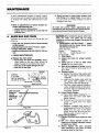
1. CHAIN
•
MAINTENANCE
_:
Sharpen the chain when: =
--wood chips are small and powdery. Wood
chips made by the saw chain should be
about the size of the teeth of the chain.
--saw has to be forced through the cut.
--saw cuts toone side
_
_
ROUND
FILE
_//
_ DEPTH
SUPPORT
=
_
FLAT SIDE
_
_
OF FILE HOLDER
_GUAGE
O1_TOP OF CUTTER
T __
TOP PLA]'E
'
. .. SIDE PLATE -o
Figure 38 .........
KEEP 30° MARK
PARALLEL
TO TH E
CENTER OF
THE GUIDE
BAR
Figure 39
18
Figure 40
":
a. SHARPENING
INSTRUCTIONS
--Model
358.356090 only (For Power Sharp_i Model
358.356100, see page 12) ....
Items required:
Gloves
Medium file .
7!32". file
Depth Gauge Tool
6" file holder
Vise
1.) Stop engine.
2.) Adjust the chain for proper tension,
page 8.
3.) Clamp bar in -a :vise to hold chain
steady. Do not clamp chain.
4.) Work at the midpoint of the bar, moving
the chain forward by hand as each cutter is filed.
5.) Sharpen cutters.
a.) Support flat side of file holder (with
7/32" round file) on cutter top plate.
Figure38.
b.) Hotd the file holder level with the
30 ° guide mark parallel to the
.center line of the bar.Figure 39.
;_.:
c.) _File from inside toward outside of
cutter, straight across, _in one direction only. Use 2 or 3 strokes per cutting edge. Figure40.
6.) Correct Depth Gauges.
.....
a.) Place depth gauge(Catal0g
No. 7136557) tool over each cutter depth
gauge. Figure 41.
b.) FiJe level with the fiat fiJe if depth
gauge is higher
than the depth
gauge tool.
c.) Maintain
rounded front corner of
depth gauge with a fiat file. Figure41.
NOTE: The very top of the depth
gauge should be flat with the front
half rounded off with a flat file.
b. CHAIN REPLACEMENT
1.)_ Replace the chain when cutters or links
break.
2.) See your Sears Service Center to
replace and sharpen individual cutters
to match your chain.
3.) Always replace the worn sprocket
when installing a new chain to avoid
excessive wear to the chain.
t
2.GUIDE BAR MAINTENANCE
• Conditions which can require guide bar
maintenance:
:
....
d.
--saw cuts to one side
--saw has to be forced through a cut
--inadequate
supply of oil to bar and
chain.
• Check the condition of the guide bar each
r time the chain is sharpened. A worn guide
bar will damage
thechain
and make cutting more difficult.
e.
Remove burrs by filing the side edges
of the guide bar grooves square with a
flat file.
Figure44.
Restore square edges to an uneven rail
top by filing with aflat file. Figure44.
MAINTAIN ROUNDED CORNER
OF DEPTH GAUGE
.030""
t
• Replace theguide bar when:
_the inside groove of the guide bar rails is
worn.
. ,: --the
guide ba r is bent or cracked.
Figure 42
a,
.... b.
Remove the guide bar to service.
Clean oil holes at least once for each
five hours of operation.
......................................................................
c:---Remove-sawd
ust from-theguide-bar ......................
groove periodically with a putty knife or
a wire. Figure43 '
i
Figure 43
I
GUIDE BAR WORN GROOVES
I CORRECT
GROOVE
_FILE EDGES
SQUARE
t
Figure44
IGNITION,
Sg
::
.
COOLING
AND
EXHAUST
• Carbon deposits will build up on exhaust
ports, spark arrestor, muffler, and spark plug
as the sawis used. All of these parts should
•be cleaned at the same .time to prevent
engine damage, overheating,
loss of power,
": and hard starting.
,
e Clean parts: _
--asrequired
: 'i_at least once for each 25-30 hours of op*
•ration
1. COOLING
AND EXHAUST
SYSTEM
• Carbon build-up on the cooling and exhaust system can cause the engine to
loose power in a cut.
• Keep the spark arrestor clean at all times.
SYSTEMS
Items required:
--wire brush
3/8" wrench
--hardwood stick
a. Disconnect.the
spark plug.
b. Remove .the muffler,
baffles,
and
screen. Figure 45,
c. Pull the starter (ope until the piston
moves far .enough to close the exhaust
ports..
d. Scrape the carbon deposits from the
exhaust ports and surrounding exhaust
chamber
using
a hardwood
stick.
Figure 46,
[CAUTION:I Do not use a metallic scraping tool to avoid damage to the piston.
• Replace the spark arrestor when breaks in
the screen are found.
SPARK ARRESTOR
HEAT SHIELD
\
MUFFLER
Figure 45
Figure 46
19
Blow out loosened carbon with compressed air.
•
f. Clean the Spark arrestor screen with a
wire brush or replace if breaks in the
screen are found.
g. Reassemble muffler parts.
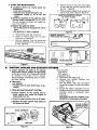
2. SPARK PLUG
,i ....
Items Required: Small brush,
tooth brush, or a pocket knife.
e.
• Maintenance is indicated when the engine
is hard to start.
• Keep the spark plug:
--clean
--properly gapped (.025")
such
as a
a.
Remove the carburetor
b.
Pull the rubber connector
from the
spark plug and remove the spark plug
from the cylinder.
cover.
c.
Clean deposits from the electrodes of
the spark plug with a small brush or a
pocket knife.
NOTE: Be careful
when removing,
cleaning,
gapping
and replacing
the
spark plug. If it is damaged, it will not
work properly and must be replaced.
CHAMPION CJ-8Y SPARK PLUG
Set the gap between the electrodes to
.025 using a wire or flat gauge. Figure
47.
d,
Replace the spark plug in the cylinder
and attach therubber
connector.
e,
f.
Figure 47
Replace carburetor
cover and knob.
/
C,
STARTER
ROPE
REPAIR
AND
REPLACEMENT
_e A starter rope that breaks next to the pulley
can be repaired.
•
Replace a starter rope that breaks more than
2 or 3 inches from thepulley.
WARNING_
Always wear eye protection when servicing the starter rope. The recoil
spring beneath the pulley is under tension. if the spring should pop out serious personal inju ry could result.
NOTE: The recoil spring, located beneath the
pulley, is under tension. If spring pops out, it
will require considerable time and effort to
reinstall. For this reason, you maywant to let
_your Sears Service Center handle this repair.
If you do try to repair the starter rope and the
recoil spring pops out, take the unit to your
Sears Service Center.
_ ....
/
/
/
MEDIUM--d_
Figure 48
_
._( _COU
TURN PULLEY
NTERCLOCKWISE
ToRELEASE
1. Remove the four screws on the side of the
fan housing. Figure48.
: :NOTE: Notice the different lengths
screws
and their proper locations
removing the screws.
of the
while
2. Remove the fan housing.
3. If the starter rope is not broken, release the
spring tension by pulling about 12 inches of
rope from the pulley and catch the rope in
the notch as shown. Figure 49.
NOTE: The tension On the starter spring will
be released if the rope has broken.
,
2O
Turn the pulley counterclockwise
spring tension is released.
.L
until
Figure 49
114"MAX. TAIL
_',
TO PREVENT
,.,-7
INTERFERENCE _'_._
WITH STARTER ___
ooos.
the
Figure 50
PULLEY
SCREW
5. Remove the pulley screw in the center of the
..... pulley. Figure 50.
_ _ _ :.. "
6. Lift the pulley carefully while gently twisting it
counterclockwise
_
, and remove the
_ old rope.
.: :
7. Move away from the fuel tank and burn the
end of the new rope to go into the pulley. '
8. Pull the burnt end while hot through
smooth it.
a_rag to
9. Feed the rope through the housing
round starter hole. Figure 50.
and the
10. Put the rope into
through the hole.
the pulley
groove
!5, Pull out 12 inches of rope and catch the rope
in. the slot in the pulley. Figure 51.
16. "rurn the pulley 3 complete turns clockwise,
,,,"_ windingup
the spring.
17. Hold the pulley and pull the starter rope to
the full extent of length and let the rope rewind slowly.
18. Replace fan housing withthe fourscrews
in
their proper location.
and up
11. Wrap rope counterclockwise
around pulley
rachet end and tuck loose end back under
rope leaving a 3/8 to 1/2 inch tail.
12. Rewind all the rope onto the pulley,
court
:
13. Set the pulley into thehousing;
and engage the spring;:
;_14. Replace
and tighten
the
pulley
turnin
....
PUSh it down
screw.
D, CLUTCH,ANDDRUM!SPROCKET
WARNING!
Do not start engine without Guide Bar, Chain,
and Bar Clamp completely
assembled. The
clutch Can come off without the guidebar and
chain co_PleteL assembled and serious injury
could resulL Do not loosen and spin the clutch
off of the crankshaft with a power too!, The
clutch shoes and drum could separate causing
the clutch to violentlyfly apart and serious personal injury could result. :_: _
:.
:;.
• Take the saw to yournearestSears
Service
Center for full. clutch'inspect{on and Service
after each 100 hours of operation./t is recommended that you do not try i to'_service the
c/utch yourse/f
un/ess you am a competent
,..... sma/[ engine mechanic and have the proper
;_ _ ,clutch service too/s. Proper disassembly and
repair of the clutch is extremely important to
the life of the engine and thesafety
of the
operator.
.....
• Clutch maintenance is requiredwhen:
--the chain continues to turn while engine
idles after the idle speed screw has been
adjusted to its capacity.
--slippage occurs during a cut.
.--a chattering noise occurs during cutting.
• Clean the clutch, drum/sprocket_ and surrounding area daily during heavy, use of the
saw: Check't0 see that the clutch drum turns
freely and Smo0thty.
• Inspect the sprocket regularly for wear. A
worn sprocket will make the chain run erratically and will Shorten the life of the bar
and chain. Figure 52.
• Replace the sprocket whenever a new chain
is installed in order to gain the full life expectancy of the chain. Use the following pro./cedure:. _
_
Items Required:
Scrench
9/16" Socket Wrench
3/4" Socket Wrench
1. Remove the:carburetor
cover and pull the
spark plug away from the rubber connector.
2. Remove the bar clamp, outer guide plate,
guide bar, and chain. Figure53.
CHAIN WEAR ON DRIVE SPROCKET
i
WEAR IS VISIBLE
ON SPUR TYPE
(Model 358.354831)
.....
RIM TyPE WEARS INSIDE
(Model 358,354871)
,,
,
Figure 52
BAR CLAMP
(_OUTER
UIDE PLATE
BAR MOUNTING
NUTS
III
6
I
L
iiii
''
21
4.
3. Remove the fan housing.
_
Use a 9!16" socket wrench on the flywheel
nut to keep the crankshaft
from moving.
Figure54.
'
NOTE: Place the socket handle forward as
shown in Figure 54.
5. Remove the clutch with a 314,. socket or end
wrench in a clockwise direction:. Figure 55.
[CAUTION:IDo not remove the clutch with a
punch or a power tool to avoid clutch damage
orbreakage.
6, Remove worn sprocket and replace.
7. install clutch in a counterc/ockwise
direction.
Figure 55,
8. Hold flywhee! bY hand and torque clutch to
22 ft. pounds.
NOTE: Do not hold a wrench on the flywheel
nut when replacing the clutch, This could
loosen the flywheel nut.
9. Reinstall fan housing, bar chain and bar
clamp.
KEEP
CRANKSHAFT
FROM MOVING
\
CLOCKWISE
INSTALL CLUTCH
COUNTERCLOCKWI
SE
Figure 55
Figure 54
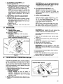
E.
CARBURETOR
ADJUSTMENTS
i
• The carburetor has been adjusted at the factory for sea level conditions. Adjustment
may
become necessary
if the unit is used at
significantly
higher altitudes or if you notice
anyof the following conditions:
--Chain moves with the engine at idle speed.
--Loss of cutting power which is not cord
rected by air filter or muffler screen clean....
ing.
--Engine
dies or hesitates when it should
accelerate.
• Permanent damage will occur to the engine if
incorrect carburetor adjustments are made. To
make the adjustment, follow the procedure below
very carefully.
WARNING!
The chainmay be moving during this procedure.
Wear your protective gear and observe all of the
safety precautions.
1. PREPARATION
22
:"
Stop engine.
b. Use a fresh fuel mixture
with proper
gasolineloil ratio.
C,
Place the saw on a solid, flat surface and
make sure the chain will not contact any
object.
d.
Locate the three (3) Carburetor adjusting
screws located on the fan housing side of
the saw. Figure 56.
e.
Turn the Low Speed Mixture Screw and the
High Speed Mixture Screw clockwise
just until they stop. Do not turn the screws
until they are tight as you may damage
the needle seats.
a.
l
]
ii
':
f. Turn the LowSpeed Mixture Screw and the
HighSpeed
Mixture S-c-few one full turn
. €ounterClockwise
_
:
i ..... i
'
m|
i
_:_"
\
ADJ.
SCRE_
i
i
,,
HIGH
_:SPEED !
ADJ.
IDLE
SPEED ADJ. SCREW t
II
Ir
1
i
iii
I
i
ii
ml
i
....
Figure 56
,
2. IDLE SPEED ADJUSTMENT--!
a. Start the engine and allow to idle.
• b. Adjust ff the engine dies or stopsby itu rning
the Idle Speed Screw 1/2 _turnclockwise
NOTE::To increase idle speed, turn the Idle
Speed Screw clockwise
_
To
decrease idle speed, turn the Idle Speed
Screw counterclockwise
c. Run the engine for a few minutes to bring it
up to operating temperature.
NOTE: The engine must beat operating
temperature for proper adjustments to be
made.
3. LOW SPEED MIXTURE ADJUSTMENT
a. Turn the Low Speed Mixture Screw slowty
clockwise
_
until the RPM starts to
drop. Note the position.
b. Turn the LowSpeed Mixture Screw counterclockwise
_
until the RPM speeds
up and starts to drop again. Note the position.
c. Set the Low Speed Mixture Screw at the
mid*point between the two positions.
4, IDLE SPEED ADJUSTMENT--II
a. Allow engine to idle.
b. Adjust if the chain is turning by turning the
IdleSpeed Screw counterclockwise
_
.
c. Squeeze the throttlei:trigger;
The saw
should accelerate without hesitating.
NOTE: tt may be necessary to recheck the
low speed mixture setting after the idle
speed has been reduced by repeating "Low
Speed Mixture Adjustment"
as in step 3
above.
ICAUTION:lNever set the High Speed Mixture
Screw less than 7/8 turn open.This is too lean
a setting and will ruin yourengine.
S=
7. CHECK
5. HIGH SPEED MIXTURE ADJUSTMENT
a. Make a test cut.
b, Adjust if the saw smokes or seems to have
tow power in the test cut by turning the
High Speed Mixture Screw t116th of a turn
clockwise
c. Repeat test cut.
d. Repeat adjustment
until the saw runs
F.
AIR
IDLE SPEED ADJUSTMENT--Ill
Recheck for proper idle mixture setting.
NOTE:, It may be necessary _to repeat Idle
Speed Adjustment-I and Low Speed Mixture.
Adjustment.
_
Adjust
ing the
turn at
til you
ACCELERATION
if there is a Slight hesitation,
by turnLow Speed Mixture Screw 1f16 of a
a time counterclockwise
_
unhave smooth acceleration.
. NOTE: Check to besure the chain is not turning when engine is idling. If chain.moves
at
FILTER
e A dirty air filter:.
ICAUTION:tNever operate the unit without the
air filter in place to avoid enginedamage.
--reduces
cutting power
--increases fuel consumption
e Clean the Air Filter:.
--frequently, especially under very dusty
conditions.
--always after 10 tanks of fuel mixture or 5hours of operation whichever is less.'
Items Required: soft bristled brush, such as a
.... paint brush.
I. Clean off the carburetor cover and the area
around it.
2. Close choke to prevent dirt from enterfng the
carburetor.
.-
FILTER
3. Remove the carburetor cover. Figure 57.
4. Remove the air filter carefutfy.
5. Soak the filter in soap and water.
tCAUTION:IDo
not use gasoline or other flammable liquid to clean the filter to avoid creating
a fire hazard.
Figure 57
COUNTER-VIBE
GJ
®VIBRATION
.
.Li
¸-
Brush away all dust and debris from the filter.
Allow filter to dry.
Brush away all debris from surfaces which
were covered by the carburetor cover.
Replace filter and carburetor cover.
SYSTEM
This saw is equipped with a counter vibration
system consisting of 5 isolator mounts. Figure
58. The Isolator Mounts protect the user from
engine, bar, and chain vibration similar to the
way shock absorbers ona car protect from jolts
and bumps in the road. _
.
_ ....
1. Check isolators each time the sawis used;
2. Replace isolators when:
--vibration increases
--mounts
develop an out of round or
swollen
shape usually
caused, from
exposure togasoline
and oili_for Jong
.....:
periods of:time.
.
-•
.
.....
6.
7.
8.
.
.....9;
3. Replace all five isolators when a failure:toone
:occurs.
. ....
_
COUNTER-VIBE""MOUNTS
/: 'i
.....
Figure 58
23
H.
STORAGE
When your ,saw is to be stored for over 30 days
always:
1,
.
Drain fuel tank in asafe manner (see Important Points, page9.)
Start Engine and allow to run at an idle
speed until the engine stops,
NOTE: This will remove most of the fuel from
the fuel system.
[CAUTION:]Wear-- protective gloves when handling thechain. The chain is sharp and can
cut you even when it is not moving.
!.
MAINTENANCE
Drain oil i_nk.
Remove, Clean, and dry the bar and chain.
5.
Store the Chain in a container filled with oil
to prevent rust.
.
Apply a coating of oil to the entire surface of
the bar and wrap it in heavy paper, cloth or
plastic.
.
Clean the outside surfaces of the engine.
8. Store the saw in a dryplace, out of the reach
of children and away from wherefuet vapors
can reach open flames from hot water
heaters, furnaces, etc.
3.
4.
ACCESSORIES
1
2
___---3
Key
No.
1
Pad
No.
55046
2
Part
NO.
24
Catalog No.
-71-36565
71-36524
71-36526
71-36557
Catalog No.
30073
71-36407
71-36711
30114
71-36627
71-36555
71-36554
71-36556
71-36370
44209
44246
51262
71-36867
51241
71-3639
Description
File Guide
Fi!e-5/32" dia.-Twin Pack
_File-7/32" dia:-Twin' Pack
Depth Gauge Tool
Description
Spark Plug-Champion CJ-8Y
Replacement Recoil Cord
Carrying Case2-Cycle Engine Oil
Bar and Chain Lubricant (gallon size)
Bar and Chain Lubricant (quart size)
Lo-Kick® Guide Bar- 18"- 358.356100
Lo-Kick® Guide Bar- 20" - 358.356090
Xtra GUARD ®Chain- Oregon® (72SG -70) - 358.356090
(requires 7/32"dia. file)
Power Sharp® Chain - Oregon ®(76 TS-66), 358.356100
(includes Stone Cartridge Assy.)
J.
TROUBLE
SHOOTING
CHART
TROUBLE
ENGINE
CAUSE
WILL NOT START
1.
2.
3.
4.
REMEDY
ignition Switch off.
Fuel tank empty.
Spark Plug not firing.
Fuel n0t reaching carburetor.
1.
2.
3.
4.
Move switch to "Start".
Fill tank with correct fuel mixture, page8.
Install new plug, page20.
Check for dirty fuel filter; ciean. Check for
kinked or split fuel line; repair or replace.
5. See Starting Instructions,
page10.
6. Contact Sears Service Center.
5. Engine flooded.
6. Compression
low.
EI_GINE'WlLL
PROPERLY
NOT IDLE-
1. Idling
speed set too low.
2. Idle speed
1. Adjust idle speed'"screw clockwise' to inincrease speed, page 22.
2. Adjust
idle speed screw counterclockw
se
to reduce speed, page22.
3. See Carburetor
Adjustments,
page22.
4. Replace seals or contact Sears Service
Center.
5. Contact Sears Service Center.
set too high.
3. Low speed screw requires adjustment.
4. Crankshaft
seals worn.
5. Compression
tow.
ENGINE WILL NOT
I. Carburetor
requires adjustment.
1. See Carburetor
Adjustments,
page22.'
ACCELERATE,
LACKS
2. Air filter dirty.
2. Clean or replace air filter, page23.
............
POWEROR--DfES ...............................................................
3:-Spark Plugffouted: ...........................................................................................................
3:-Cre-ati-dt-repladeSp-atk--PtfJ-g_-hd-f'-e-g_p;
IN THE CUT
page 19.
page20.
4. Carbon build-up.
4. Clean exhaust system including spark
arrestor, page 19:
5.
Low Compression.
5. Contact Sears Service Center.
ENGINE SMOKES
EXCESSIVELY
•
Choke partially on.
2. High speed needle requires
3,
Air filter dirty.
4. Oil rich fuel mixture.
5. Crankcase
ENGINE
RUN'S'HOT
1.
2.
3.
4.
adjustment.
leak.
,5.
Fuel Mixture Incorrect.
2. Spark Plug Incorrect.
3. Carbon build-up.
4. High Speed Mixture
Push Choke in.
See Carburetor
Adjustments,
page22.
Ctean or replace air filter, page23.
Empty fuel tank and refill with correct
mixture, page&
Contact Sears Service Center.
..............
fuel
1. See Engine Fuel Mixture, page8.
2. Replace with correct plug, page20.
3. Clean exhaust.sys:tehns
including
spark
arrestor, page 19.
4. See Carburetor
Adjustments,
page 22.
set too low.
i......................
OIL INADEQUATE
FOR
BAR AND CHAIN
LUBRICATION
I. Oil tank empty.
2. Oi! pump:or oil filter clogged.
3. Guide bar oil hole blocked.
1. Fill oil tank, page9.
2. Contact
Sears Service Center.
3: Remove barand clean, page 19.
CHAIN MOVES
IDLE SPEED
1. Carburetor
requires adjustment.
2. Clutch requires repair.
1. See Carburetor Adjustments,
page22.
2. Contact Sears Service Center.
CHAIN DOES NOT MOVE
WHEN ENGINE IS
ACCELERATED
1.
2.
3.
4.
1.
2.
3.
4.
CHAIN CLATTERS OR
'CUTS ROUGH LY
1. Chain tension incorrect.
2. Cutters dull, improperly
sharpened; depth
gauges too high.
3. Sprocket
worn.
4. Chain wear due to Contact with dirt, Sand
or frozen wood.
5. Cutters damaged after striking foreign
material.
CHAIN STOPS Wi"T'HIN
1. Chain cutter
AT
Chain tension too tight.
Carburetor
requires adjustment.
Guide bar rails pinched.
Clutch slipping.
tops not filed
flat.
THE CUT
21 Guidebar
3_ Clutch
CHAIN CUTS AT
AN ANGLE
1. Cutters
burred
or bent;
rails uneven.
slipping,
damaged
on one Side.
2. Chain dull on one side.
3. Guide bar bent,
or worn.
See Chain Tension, page8.
See Carburetor
Adjustments,
page 22.
Repair or replace, page 7 & 19.
Contact Sears Service Center.
1. See Chain Tension, page 8 .
'............
2. See Chain Sharpening Instructions,
page
page 18 (page 12-13 for Power Sharp "),
3. Replace, page 21.
4. Resharpen or replace Chain, page 18-19
(page 12-!.3 for Power Sharp").
5. Contact Sears Service Center.
Sharpen n!l cutters evenly and uniformly
or replace chain. See chain sharpening
instructions,
page 18-19 (page 12-13
for Power Sharp" ).
I
1. See Chain Sharpening instructions,
page 18-19 (page 12-13 for Power Sharp ").
2. Repair or replace guide bar, page 7 & 19.
3. Contact Sears Service Center.
1. Resharpen until all cutters have equal
angles and lengths, page 18-19 (page 12-13
for Power Sharp'').
........
2. Resharpen until all cutters have equal
angles and lengths, page 18-19 (page 12-13
: 3.. Replace
for Powerguide
Sharp").
bar, page 7 & 19.
25
MAINTENANCE
CHART
"
,i
" ==__i 8"
Complete
Visual inspection (condition, leaks)
.....
machine
X
clean
Throttle trigger, safety throttle Ioc4k,stop switch
Check operation
x
x
10
Clean Felt
x
Filter in fuel tank
...............................................................
.....
..................
X
....................
_ ......... RepJace f#__.............................................................................................................................................................................
Fuel tank
Clean
x
Chain oil tank
Clean
x
Chain lubrication
Check
x
i
9
inspect, also check sharpness
x
x
Check chain tension
x
x
Saw chain
8
Sharpen
inspect (wear, damage)
x
19
Clean
Guide bar
x
Lubricate sprocket nose
x
:
x
x
Check
19
19
Replace
Clean
19
x
Deburr
Chain sprocket
18
x
x
7
21
x
x
x
23
Air filter
Replace
Cooling inlets
Clean
Cylinderfins
Clean
Check idle adjustmentchain must not turn
Carburetor
x
19
t9
x
x
22
x
x
Readjust idle
Spark plug
All accessible
23
x
Readjust electrode gap
x
22
20
screws and nuts
(not adjusting screws)
Retighten
Vibra_on mounts
Inspect
...........................
To be replaced by a qualified Service Dealer
x
23
x
x
Inspect
19
Clean or replace
19
Spark arrestor screen
26
•NOTES
27
SEARS CHAIN SAW PARTS LIST
MODELS
358.356090
358.356100
3.7/20"
3.7/18" PS
Figure I
49
43
36
23
44
_--2
_-31
,25
26
29
60
61
10
59
12'
56
46 50 51
/
28
SEARS CHAINSAWPARTS
MODELS
358:356090
3.7/20"
LIST
358.356100
3.7/18"PS
Figure 1
2
3
,41
5
6
7
9
Part No.
Qty.
39095
1
23817
2
STD522525
15434
24476
1626
1722
2
2
1
1
1
15123
1
10
11
12
13
14
15
16
STD600603
30054
42053
24329
42051
42066 .......
15364:.
17
18
19
2O
10720
24392
24391 STD522505
1
1
1
2
_
21
22
23
24
25
26
27
28
29
24385
24384
1'9097
STD600603
24232
_ 28487
1
2
2
2
1
1
1
1
2
2
2
1
1
1
1
30
31
32
33
34
35
36
24388
24387
32051
_:_!5354
30039
42056
42052: i
12067
19098 _.
10696
10699
2
1
1
1
1
1
1
1
Description
Flywheel Assembly
(incl. # 2)
Spring - Starter Dog
Screw- Muffler Cover
Screw - Spur
Spur
Washer- Flywheel
Flywheel Nut
Washer- Starter Pulley.
Retainer
Screw Disc Mounting
Sealant Crankcase 3 oz.Optionai
Disc - Recoil Spring Outer
Bushing - Recoil Spring
.Spring- Starter Recoil
Disc-Recoil
Spring Inner
Screw- Fan Housing
(Top Front)
. Fan Housing Assembly
Shield Muffler
Muffler Cover
Screw- Muffler
Body/Cylinder
Screen - Spark Arrestor
DiffuserMuffler
Seal- Crankshaft
Screw - Air- Baffle
Baffle ;Air
Pulley-Starter
Back Plate - Muffler
Muffler Body
Bearings
Crankshaft
Thrus t WashersCrankshaft
Kit- Bar Stud Replacement
Handle- Starter Rope
Rope- Starter
Cylinder
Gasket- Cylinder
Crankcase Assembly
Right & Left Half
(incl. #23, 29, 31 & 50 on Fig. 1 ;
also includes from Fig. 3, #22,
30, 43 & one of 37.)
358.356090
358.356100
Key No.
Part No.
37
15365
38
39
30073
15195
40
4t
25933
24492
43
44
Qty.
IDescdption
1 Screw- Fan Housing
(Lower Front)
1 Spark Plug (CJ-8Y)
1 Clip- High Tension
Lead Cylinder
2
Piston Ring
1 Crankshaft and
Rod Assembly
39096
10626
1
1
45
46
47
48
49
STD580008
15366
39097
39071
39102
1
50
10444
1
51
52
19119
24334
!
1
53
39093
1
54
55
56
57
58
59
6O
61
62
15425
23661
STD600603
STD511007
23732
39099
23575
24858
31107
66371
2
2
2
9
1
1
1
1
1
1
High Tension Lead
Piston Assembly Kit
(incl. #40 and pin)
Key- Flywheel
Screw- Fan Housing (Rear)
Boot - Spark Plug
Connector - Spark Plug
High Tension
Lead Assembly
(Incl. #43, 47, & 48)
Oil Cap Assembly
(Incl. #51)
"O" Ring - Oil Cap
Clamp- High Tension Lead
(Crankcase)
Ignition Module (incl. #49 &
59)
Screw- Module Mounting
Clamp- Lead
Screw - Lead Clamp
Screw- Crankcase
Switch - Toggle
Switch Lead
Ignitior_ Switch Nut
Plate:': Start/Stop
Scrench
Operator's Manual (not shown)
26468
1
Decal Fan Housing
Decal
A
_
1
1
1
29 ¸
SEARS
MODELS
CHAIN:SAW
PARTS
358.356090
3.7/20"
Figure
LIST
358.356100
3.7/18"PS
2
MODEL
358.356100
3.7/18"PS (only)
,28
38-39
4
1
45
CARBURETORASSEMBLY
PART NO. 35094
8--_.
1
15_h_, +, _
"+J'_/_
4
_30
.....
+] ++_.o_+_ 27
5._-_
_'_"17_--
/7" 11_i
' 12-_,_
13--_
\is
+-19
°-20
:2
SEARS
MODELS!
_:
Pad No.
25919
STD511003
10347
19107
24229
Qty.
1
1
1
1
1
6
7
19101
15194
1
2
8
9
11965
24383
1
1
11
19099
1
12
13
15462
24373
2
2
t4
15
16
17
18
19
20
21
22
23
24376
25258
24349
15414
21028
15252
23364
23363
19122
10286
2
1
1
2
1
1
1
1
1
1
24
25
26
27
28
12023
24357
32053
25469
15245
1
1
1
1
2
Key No.
1
2
3
4
5
CHAIN
SAW PARTSMST
358.356090
3.7/20"
Description
Choke Rod
Screw - Choke Bracket
358.356100
3.7/18"PS
Figure 2
Key No.
29
30
Bracket & Bushing Ass'y
Seal - Carburetor
Adaptor
Adaptor CarburetorfCylinder
Gasket - Adaptor/Cylinder
Screw - Brace to
Rear Handle
Brace- Handle
Wire - Choke
Gasket Carburetor
to Adaptor
Shoulder - Screw -tsolator
IsolatorPowerhead
to Rear Handle
Cup- Isolator
Spacer - Isolator (Center)
Bracket - Carburetor Seal
Screw - AdaptorfCylinder
Fuel Line
Washer Fuel Pick-Up
Filter- Fuel Pick-Up
Weight- Fuel
Seal- Fuel Tank Neck
Fuel Tank Assembly
(Incl. # 30& 34)
Rear Handle - Right
Throttle Lock
Bushing Throttle Lock
Spring - Trigger
Screw- Carburetor/Adaptor
Pa_ No.
19104
28505
Qty.
Description
1 Seal Adaptor
1 Fuel Line and Filter
Assembly (1n cl. #t8,19, 20 & 21)
1 Bushing - Trigger
1 Throttle Link
3 Screw - Cylinder Shield
to Crankcase
1 Fuel Cap Assembly
(Incl. #35)
1 vO" Ring Fuel Cap
1 Trigger- Throttle
31
32
33
32059
24699
15168
34
10331
35
36
STD302213
26013
38
39
24482
1
1
!
40
41
42
43
24976
25486
24378
-11826
15369
15393
1
1
2
1
44
45
15397
24877
1
1
46
47
48
49
Decals
A
24548
19114
25895
25425
t
1
1
1
26471
26529
25586
P
1
1
I
B
Knob
Cover - Carburetor
358.356090
358.356100
Ass'y.
Spring - Throttle Lock
Rear Handle- Left
Screw- Rear Handle
Screw- Rear Handle
(Throttle Lock)
Screw - Rear Handle (Lower)
Retaining Ring - Carb.
Cover Knob
Air Filter
Gasket - Air Filter
Cylinder Shield
Knob - Adjusting (358.356100)
Decal- Starting Instructions
358.35609O
358.356100
Decal - Sharpening Instructions
(358.356100)
CARBURETOR
ASSEMBLY
PART NO. 35094
Key No.
1
2
3
4
5
6
7
8
9
10
11
12
13
14
15
16
17
Pa_ No.
35102
35015
35123
35119
35101
351!5
35099
35109
35113
35069
35111
35106
35118
35097
35125
35105
35107
Qty.
1
3
1
1
1
1
1
1
1
1
1
1
1
1
!
1
1-
Description
Valve-Throttle
Screw- Valve
Fitting -Inlet (Elbow)
Spring - Throttle Ret
Shaft Ass'y - Throttle
Screw - Pump Cover
Cover- Fuel Pump
Gasket - Fuel Pump
DiaphragmFuel
Screen - Inlet
Gasket- Circuit
Valve- Inlet Needle
Spring - Mtrg. Lever
Lever - Throttle (Outer)
Bushing- Throttle Lv.
Stop - Throttle
Ball-Choke
Friction
Key No.
Pa_ No.
Qty.
18
19
20
21
22
23
24
25
26
35022
35124
35096
35126
35116
35108
35114
35098
35021
35104
35103
35121
35117
35122
35023
t
1
1
1
2
1
1
1
4
1
1
1
1
2
2
•
:27
28
29
30
31
32
Description
Spring - Choke Friction
Screen - Check Valve
Ring - Screen Retaining
Plate Ass'y - Circuit
Screw - Circuit Plate
Gasket - Mtrg. Diaphragm
Diaph. Ass'y- Mtrg.
Cover- Mtrg.lDiaphragm
Screw Ass'y - Mtrg. Cover
Valve- Choke
Shaft Ass'y - Choke
Spring- idle Screw
Screw- Idle - Adj.
Needle. Hi & Lo
Spring : Needle's
31
SEARS CHAIN SAW PARTS LIST
MODELS
358.356090
358.356100
........
3.7/20"
3.7/18"PS
Figure
3
51
B
See
1 #36
CHAIN
REPAIR
KIT
\
,43
44
I
72
\
14
,5/._
49
57
32
33
41'
10
64
57
12
68
i
MODEL
358.356100
3,7/18"PS
(only)
67
L
32
• 58
SEARS CHAINSAW PARTS LIST
MODELS
358.356090
358.356100
3.7/20"
3.7/18"PS
Figure 3
Key No.
Part No.
Qty.
1
STD5t1003
1
2
3
5
6
7
24351
24348
15357
32049
1
1
1
1
!
8
9
10
48069
48071
24465
24353
1
--
10291
10466
24352
1
1
3
13
14
15
16
26246
25428
23373
24347
24225
15406
1
1
1
1
1
1
17
18
19
20
21
22
23
23356
STD583037
23357
24467
15509
STD560907
19103
1
1
1
1
3
1
1
24
25
26
27
28
2615
19029
15418
23358
10638
1
1
1
1
1
11
12
29
30
32
33
34
24677
21038
23699
22197
10289
1
1
1
1
1
35
36
37
38
39
24676
21031
2464
24691
24345
1
1
2
1
1
Description
Screw-Bracket to
Crankcase
Bracket-Lever to Crankcase
Lever- Manual Oiler
Thrust Washer
Bearing - Clutch
Drum & Sprocket Assembly
358.356090
358.356100
Plate - Clutch
Key No.
40
41
42
43
44
46
47
48
Spring. Clutch
49
Clutch Ass'y.
50
(Incl. #9, 11 &12)
51
358.356090
52
358.356100
53
Shoe Clutch
Spider - Clutch
54
358.356090
358.356100
Boot - Oiler Rod
55
Rod. Manual Oiler
Isolator.
Crankcase Side
56
Screw-Side Isolator/
Crankcase
57
Cap- Oil Pump
58
Retainer Ring.Oil
Pump
Plunger- Oil Pump
59
Cap- Handguard
60
Screw/Handguard
61
Cotter Pin -Vent
62
Gasket Body
63
to Crankcase
64
Tubing Nut- Oiler
65
Quad Ring -Oil Pump
Washer. Oiler
66
Spring- Oil Pump
Oil Pump AssemblyAuto/Manual (Incl. #17, t8, .67
19, 24, 25, 26, 27, 30, 32,
68
33, 34, 38, 39, 40, 41, 42 &
one of 37)
69
Spring - Oil Line Protector
70
Discharge Oil Line
Spring - Diaphragm
71
Button and Pintle Assembly
72
Oil Line Pick-Up Assembly
(Incl. #29, 35 and 36)
Decal
Weight - Oil Pick-Up Line
A
Oil Line
B
Sleeve - 118 Tubing
m
Filter-Oil
Pump Vent
Diaphragm - Oil Pump
--
Part No.
Qty.
Description
19102
25987
15297
15422
25925
STD510810
24399
1
1
1
1
1
3
1
10727
1
Gasket - Cover to Body
Cover- Pump
Screw-Oil Pump Cover
Tubing Nut - Crankcase
Guide Bar Plate - Inner
Screw - Pump to Crankcase
Cover Plate - Oiler
Bar Clamp Assembly
(incl. #59, 62, 63 & 64)
358.356090
25924
STD600603
24466
22258
STD522510
1
4
1
1
2
51262
51241
44209
44246
15362
1
1
1
1
2
24373
24376
2
4
25044
15445
15361
STD581018
25414
15385
15549
1
2
1
1
1
1
1
48071
1
15484
4746
1
1
25421
69099
1
1
STD511005
52079
2
--
26468
25631
26550
1
1
1
26545
1
Guide Bar Plate- Outer
Screw Oiler Cover Plate
Handguard
Handle Bar Assembly
Screw - Handlebar/
Rear Handle
Chain
358.356090
358.356100 - Incl. #70
Bar-18"SN
Bar- 20"SN
IsotatorMount
Spacer
Front Handlebar
isolator- Front Handlebar
Isolator CuDs- Front
Handlebar
Pin - Bar Adj.
Flange Nut- Bar Mounting
Spacer- Isolator
E Ring- Adj. Screw
U-Clip- Bar Clamp
Screw- Bar Adj.
Screw - Isolator Mount to
Handlebar
Clutch Drum & Adaptor
Ass'y. - (7 SpHne 3/8P) (358.356100)
Plate Clutch (358.356100)
Floating Rim- Sprocket
(3/8P- 7 Tooth)- (358.356100)
Slide Button
Stone & Carrier Ass'y.
(IncL #69) - (358.356100)
Screw- (358.356100)
Chain Repair Kit (358.356090
only) optional
Decal Strip- Bar Clamp
Decal Handguard
Decal Chain TensioningNot Shown
Decal- WarrantyGuide Bar- not shown
33
:
r
34
¸¸
NOTES
QUICK REFERENCE
PAGE
Read and follow all Safety Rules, Precautions and Operating Instructions.
Failure to do so can result in serious personal injury.
SAFETY RULES AND PRECAUTIONS
.................................
PREPARATION
................................................................
1.
2.
3.
4.
5.
page
3-4
3
Wear personal protective gear -- gloves; safety footwear; snug fitting clothing; and eye,
hearing and head protection.
Check for worn, loose, or damaged parts and repair or replace as necessary.
Check the chain for sharpness and tension.
Keep children, bystanders and pets out of the work area.
Plan your sawing operation carefully in advance.
FUEL AND OIL
2.
3.
4,
5.
6.
• ...........
_
Use 1 part air-cooled, 2-cycle engine oir to 16 parts regular gasoline.
Use gasol.ine not over 2 months Old,
Mix, store and pour fuel in an approved, marked container and in a well-ventilated
Move a minimum of 10 feet away from fuel and fueling site before starting engine,
Fill the oil tank each time the fuel tank is refueled.
STARTING
THE ENGINE
8
area.
.........................................................
10
!.
Hold saw firmly with the saw chain free to turn without making contact with any object.
2.
Push saw away from you with your right hand while pulling the starter rope with your left hand,
3. Use no more than 15-18 inches of rope per pul!.
4.
Pull rope no more than 5-6 times.
......
5.:
Release the trigger after engine starts allowing engine to idlel
OPERATING
1.
2.
3.
4.:
5.
6.
THE UNIT .........................................................
Cut wood only.
Accelerate the engine
Begin cutting with the
Cut onty at fuji throttle.
Release the trigger as
Stop the engine before
MAINTENANCE
.
2.
3.
4.
,
6.
,
8.
14
to full throttle before entering the cut.
saw frame up against the tog.
soon as the cut is completed.
setting the saw down after cutting,
..............................................................
18
Adjust or have the carburetor adjusted if the chain moves when the engine idles.
Disconnectspark plug before performing:maintenance
except for carburetor adjustment.
Check the guide bar for wear each time the chain is sharpened.
Clean the air filter frequently and always after 10 tanks of fuel mixture or 5 hours of operation,
whichever is less.
Clean igniton; cooling and exhaust systems at least once for each 25-30 hours of operation.
Take the saw to your Sears Service Center for full clutch inspection after each 100 hours
of operation.
Drain_fue/tank in a safe manner after each use.
Store sawin a dry place out of the reach of children.
WATCH OUT FOR
KICKBACK
THE SAW WHEN
IT NEEDS REPAIR
NEVER USE THE SAW
WHEN TIRED
USE A FIRM GRIP
WITH BOTH HANDS
iiii
i
i
The Model Number
will be found under the handle with the Serial
Number. Always mention the Model Number when requesting
vice or repair parts for your Chain Saw.
[Sears]
All parts listed herein may be ordered from any Sears
and most Sears Stores.
Service Center
WHEN
ORDERING
REPAIR
PARTS,
ALWAYS
GIVE
FOLLOWING
INFORMATION AS SHOWN IN THIS LIST.
The PART NUMBER
3.
The PART DESCRIPTION
2.
The MODEL NUMBER
4.
The NAME OF iTEM
Chain Saw
PS
If the parts you need are not stocked locally,
electronically
transmitted
to a Sears Repair
center for expedited handling.
When you
from Sears
something
can offer ...
,_,
-: ....
,
How to Order
your order will be
Parts Distribution
buy
you
that
Sears
merchandise
get an extra
nobody else
Seryice.
Across
town or across
the
country, Sears_Service follows
you, pr0_.,iding
trustworthy ,
competent" service technicians
using
only Sears specified
factory parts.
•
.I-
Repair
THE
1.
358.356090-3.7/20"
358.356100-3.7/18"
MODEL NO.
358.356090-3.7/20"
358.356100-3.7/18"PS
ser-
;)',
,
Parts
SEARS SERVICE
)
-:
,
,
:
i
_flll
if
1hiilll ii
:%
",1
I
Sca_-s,
Roebuck
:
]
and
<
;
Co.,
°
Chicago,
1:
Ill. 60684
"
U.S.A.
,,, ,,,, ,,,,
66371-1-12084-2-17884
PRINTED IN U.S.A.