1
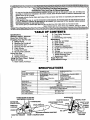
IMPORTANT MANUAL
Do Not Throw Away
__.ARS
operator's
manual
•
•
•
•
Assembly
Operation
Maintenance
Repair Parts
MODEL NO.
358.356091-3.7120"
358.356101-3.7118"PS
_A/RSICRRFTSMRN I
3.7/20"
3.7,/t8"PS
GASOLINE CHAIN SAWS
i1:
AWARNING
This chainsaw is capableof severe
kickbackthatcouldtesultin serious
lr_uryto theuser.Do notoperatethis J
saw unless you haveextraordinary
cuttingneeds,and ha_especialized
trainingand experiencefor dealing
with kickback.Chainsawswith slgnificantlyreducedkickback potential
areavailable.
i,,,ii
ii
Record in the space provided below the Model N% and Serial No. of
your saw. These numbers are located on the starting instructions
decal.
M6del No.
Serial No.
Retain these numbers
for future reference.
,i
Sears,
Roebuck
and
Cx)., Chicago,
Ill. 60684
U.S.A.
.
530-066648-5-21188
©Sears, Roebuck and Co., 1988.
FULL
ONE YEAR WARRANTYON GASOLINECHAINSAW
(ExcludingBar_Chain_Spark Plu9, A!r Filterand Starter Rope)
operating
i
_
and maintenanceinstructions
in the owner's
Searswill repair aetectsin mazedal
manual,
or workmanship
in this
gasoline chainsawat no charge.
This warranty excludesthe bar, chain, spark plug, air filter, and starterropewhichare expendable parts and becomeworn
Forone
year fromdate of purchase,
during normaluse.
..... whenyou maintain, lubricate, and tune up this gasoline chain saw according tothe
._
If this
gasolinechain,saw is usedfor commercial or rental p_Jrposes, this warranty applies for only 30 days fromdateof
purchase.WARRANTYSERVICEIS AVAILABLEBYRETURNINGTHE CHAINSAWTO THE NEARESTSEARSSERVICE
._
Thiswarrantygivesyou specificlegal dghts,and youmay alsohaveotherrights whichvaryfromstateto state.
CENTER/DEPARTMENT
IN THE UNITEDSTATES.
'"
-.
.<
TABLE OFCONTENTS
B. Tree Felling Techniques ...................
C. Bucking ...............................
D. Debranching and Prunin.g .................
Maintenance
A. Guide Bar and Chain .....................
B. Spark Arrestor ..........................
C. Starter Rope ............................
D. Carburetor Adjustments ...................
E. Clutch and Drum/Sprocket .................
F. Air Filter ...............................
G. Storage ................................
H. Maintenance Accessodes .................
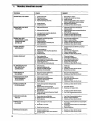
L Trouble Shooting Chart ...................
J. Maintenance Chart .......................
Repair Parts List ............................
Quick Reference Page ........................
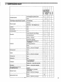
Specifications ...............................
2
SPECIAL SAFETY SECTION ...............
3, 4 & 5
Know Your Chain Saw ........................
6
Preparing Your Saw For Use-.,
"
7
A; Getting Ready ..................
:.. ......
7
B. Attaching the Handguard ..............
....
7
C. Attaching the o,_r,....
7
D. Attaching the Bar and Chain .......
. ........
8
E. Chain Tension ...........................
9
F. Fueling Your Engine ...............
........
9
G. Bar and Chain Lubricant.
... 10
Using Your Saw ........................
"....
11
A. Control Devices
" 11
B. Starting Instructions
.... -.................
11
Using the Power Sharp" System ..............
12
Types of Cutting ............................
14
A. Basic Cutting Technique ..................
14
14
16
17
18
19
20
21
22
22
22
23
24
25
28
35
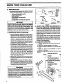
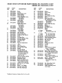
SPECIFICATIONS
MODEL
_r_K6091{3.7/20
cu:iN.DISPU_CE.E.Ti
3.7 cu. in J60 cu. cm.
20"SprocketNose-StockNo.7t_
318Extended 'Pitch
GUIDE
CHAIN
BAR - L,O*KICK"
_)
,,,
,,
,
,358.356101(3.7/t6"1_.S.)
3.7 cu.
18" Sprocket Nose
318 _'
Pitch
" O_,gon®
OtegorP
Power
Sham
_
ChromeCutters*70 DriveLinks: Stock No.T1-36867
SPARK PLUG'
SPARK PLUG GAP
,,
"
ChromeCutters'-66 DriveLinks
_'tock No. 71-3639
Champion cJ-aY
,,
_025"
Solid State'
IGNITION
MODULE
StockNo.7t-36370
.008 to .014
AIR GAP
..
FUEL MIX
' ......
Gasoline/Oi! Mitre
Spark Arresting
MUFFLER
OILER SYSTEM
FUEL TANK CAPACITY
Automatic
..........
....
OIL TANK CAPACITY
16:1 (_
/ USDA
"Fueling YourEngine';)
Approved,,
/ Manual
.......
19 oz. 562 cu. cm.
......
12 oz. 355 cu. cm.
,,
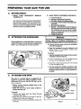
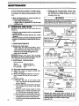
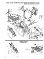
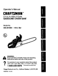
HANDGUARD
POWER SHARP ADJUSTING
KNOB (MODEL 358.356101 )
STARTER HANDLE
AIR FILTER
COVER
LOW-KICKBACK CHAIN
.ER
THROTTLE
DE
CHAIN TEI_SION
THROTTLE
LOCKOUT
I SWITC
CHOKE'
REDUCED-KICKBACKGUIDE BAR
TRIGGER
CHAII_ATCHER
FU
REAR !HAIN
CATCHER
UL I
i
SPECIAL
GUARD
I
IHIIIIIIIIIIIJlIJl
SAFETY
AGAINST
II
I
II
I
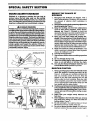
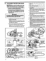
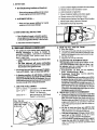
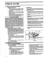
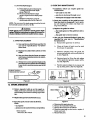
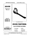
1.
A KICKBACK WARNING
Kickback can occur when the moving chain contacts
an object atthe upperportionof the tip ofthegulde bar
or when the wood doses in and pinches the saw chain
in the cut. Contact at the upper portion of the tip of the
guidebarcan causethechaintodig into theobject and
atop the chain for an Instant. The result is a lightning
fast, reverse reaction which kicks the guide bar up and
back toward the operator, ff the saw chain is pinched
along the top of the guide bar, the guide bar can be
driven rapidly back toward the operator. Either of
these re=icti0ns Can Cause io_,sof saw control which
can result in serious injury.
KICKBACK
PATH
3.
4.
5.
6.
7.
8.
9.
10.
AVOID
OBSTRUCTIONS
AREA
Figure 2
t
STAND
TO THE
LEFT OF
THE SAW
ELBOW
I_.OCKED
LEFT HANo
-"
Figure 3
roll=l,
,,,,,,H,II
f
ON
UNDER SIDE
OF HANDLEBAF_
1.
OF
ReCognize that kickback can happen. With a
basic understanding of kickback, you can reduce
the element of surprise which contributes to
_ccidents.
Never let the moving chain contact anyobject at the
tip of the guide bar. Figure 1.
Keep the working area free from obstructions
such as other trees, branches, rocks, fences,
stumps, etc. Figure 2. Eliminate or avoid any
obstruction that your saw chain could hit while you
are cutting through a particular log or branch.
Keep your saw chain sharp and properly tensioned. Followmanufacturer's chain sharpeningand
maintenance instructions. Check tension at regular
intervalswiththe engine stopped,neverwiththeengine
running.Make sure the bar clamp nuts are securely
tighter,ed after tensioning the chain. A _
or dull
chain can increase the chance of kickback to occur.
Begin and continue cutting ait full throttle. If the
chain is moving at a slower speed, there is greater
chance for kickback to occur.
Cut only one log at a time.
Use extreme caution when re-entering a previous
cut.
Do not attempt plunge cuts.
Watch for shifting logs or other forces that could
close a cut and pinch or fall into the chain.
Use only the Reduced-Kickback Guide Bar and
Low-Kickback Chain specified foryoursaw.
MAINTAIN
Figure 1
I
I I
REDUCE
THECHANCE
KICKBACK
KICKBACK
2.
NEVER
REVERSE
HAND
POSITIONS
.
SECTION
Kickback is a dangerous reaction that can lead to
serious injury. Do not rely only on the safety
devices provided with your saw. As a chain saw
user, you must take special safely precautions to help
keep your cutting jobs free from accident or injury.
CLEAR
WORKING
/
CONTROL
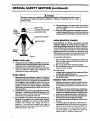
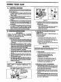
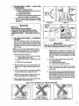
Keep agood firl_ grip on the saw with both hands
when the engine is running and don't let go.
Figure 3. A firm.grip can neutralize kickback and
help you maintain control of the saw. Keep the
•
fingers of your left hand encircling and your left
thumb under the front handlebar. Keep your right
hand completely around the rear handle whether
you are right handed or left handed. Keep your left
arm straight with the elbow locked.
2. Position your left hand on the front handlebar so it
is In a straight line with your right hand on the rear
handle when making bucking cuts. Figure 3. Never
reverse right and left hand positions during any lype
of cutting.
3. Stand with your weight evenly balanced on
both feet.
4. Stand slightly to the left side of the saw, to keep
your body from being in a direct line with the
cutting chain. Figure 3.
5. Do not overreach. You could be drawn or thrown
off balance and lose control of the saw.
6. Do not cut above shoulder height. It is difficult to
maintain control of the saw above shoulder height.
SPECIAL
_
i
SAFETY
i
SECTION
i
(continued)
iml.
,,,
..............
j
i
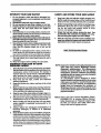
,i_ WARNING
Because a chain saw is a high-speed wood-cutting tool, special safety precautions must
be observed to re(zuce the risk of accidents,
Careless or improper use can cause
.serious injury.
4.
Do not attempt to use your chain saw during b
weather conditions such as strong wind, ralnz sn(
etc., or at night.
5. Plan your sawing operation carefully in advance.
not startcutting untilyou have a clear work area, sect ,-footing,andifyouare fellingtrees, aptanned retreatp_
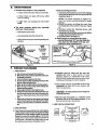
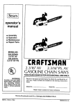
SNUG
FITTING
SAFETY CHAPS
Figure4
1.
2.
1.
2.
3.
YOUR
SAW
Read your Operator's Manual carefully untilyou completelyunderstandand followagsafetyrotes and operating
instructionsbefore attemptingto operate the unit.
I_estdct the use o'fyour saw to adult users who understagd and follow the safety rules, precautions, and
operating instructionsin this manual.
PLAN
REACTIVE
FORCES
Pinch-Kickback and Pull-in occur when the chain
suddenly stopped by being pinched, caught, or
contacting a foi_ign object in the wood. This resultsi
reversalofthe chainforce usedtocutwoodand causesthes
to move inthe opposite directior_of chain rotation.Pine
Kickback drives the saw straightback toward the opera
Pull-inpuffs the saw away from the operator.Eitherreactk
can result in loss ofcontrol and possible serious inju_.
SAFETY
SHOES
,KNOW
_AVOID
AHEAD
Wear personal protective gear. Figure 4, Always use
steel-toed safety foQtwearwith non,slipsoles;snug-fitting
clothing; heavy-dutynon-slipgloves;eye protectionsuch
as norvfogging, vented goggtes or face screen; an approvedsafety hardhat, and sound barriers-- ear plugs or
mufflers to protect your hearing. Regular users should
have headng checked regularly as chain saw noise can
damage hearing.
Keep children, bystanders, and animals out of the
work area-- a minimum of 30 feet (10 meters). Donot
allow other people or animals to be near the chain saw
when startingor operatingthe chain saw.
Do not handle or operate a chain saw when you are
fatigued, ill, or upset; or if you have taken alcohol,
drugs or medication. You must be in good physical
condition and mentally alert. Chaip saw .work is
strenuous. If you have any condition that might be
aggravated by strenuous work, check with your doctor
before operating a chain saw.
To avoid Pinch-Kickback:
1,
2.
3.
Be extremely aware of situations or obstructk
that can cause material to pinch the top of or otf
wise stop the chain.
Do not cutmore than one log at a time.
Do not twist the saw asthe bar is withdrawn from
under-cut when bucking.
To avoid Pull-in:
1.
2.
Always begin cutting with the engine at full thin
and the spur against the wood.
Use wedges_nade of plastic or wood, (never of me
to hold the cut open.
HANDLE
1.
2.
3.
4.
5.
6.
7.
FUEL WITH
CAUTION
Eliminate allsources of sparks or flame in the ar
where fuel is mixed, poured, or stored. There sh(
be no smoking, open flames, or work that could ca
sparks."
Mix and pour fuelin an outdoor area, on bare grou
store fuel in a cool, dry, well-ventilated place; and
an approved, marked container for all fuel purpo.,
Wipe up all spilled f_el before starting your.,
Move at least 10 feet (3 meters) away from fuel
fueling site before starting the engine.
Oo not smoke while handling fuel or while opera
the saw.
Turn the engine off and let your saw cool in a I
combustible area, not on dry leaves, straw, paper:
Slowly remove the fuel tank cap and refuelthe unit.
Store tool and fuel in an area where fuel vapors
not reach sparks or open flames from water hea
electric motors or switches, furnaces, etc.
OPERATE
YOUR
SAW SAFELY
1.
Do not operate a chain saw that is damaged, improperly adjusted, or not completely and securely
assembled.
2. Operate the chain saw only in outdoor areas.
3. Do not operate the saw from a ladder or in a tree.
4. Position all parts of your body to the left of cut and
away from the saw chain when the engine is
running.
5. Cut wood only. Do not cutmetal; plastics,masonry,'nonwood bu,ding materials, etc.Do not use yoursaw to pryor
shove away limbs, rootsor other objects.
6. Make sure the chain will not makecontact with anyobJectwhile startingthe engine. NeverWto stadthe saw
when the gu'rdebar is in a cut or kerf.
7. Use extreme caution when cutting small size brush
and saplings. Slender material can catchlthe saw
chain and be whipped toward you or pull you off
balance.
8. Be alert for springback when cutting a limb that is
under tension so you will not be struck by the limb or
saw when the tension in the wood fibers is released.
9. Do not put pressure on the saw st the end of a cut.
This can cause you to lose control when the cut is
completed.
10. Stop the engine before setting the saw down.
MAINTAIN
WORKING
1.
2.
3.
4.
5.
6.
YOUR SAW IN GOOD
ORDER
Have all chain saw service performed by your Sears
Service Center withthe e00cept_ oftheitems listedin the
maintenance section of this manual. For example, if
improper tools are used to remove or hold the flywheel
when servicing the clutch, structural damage to the
flywheel c_ occur and cause the flywheelto burst.
Keep fuel and oil caps, screws and fasteners
securely tightened.
Keep the handles dry, clean, and free of oil or fuel
mixture.
Make certain the saw chain stops moving when the
throttle trigger is released. Forcorrection,referto page
24 for carburetor idle adjustment instructions.
Stop the saw if the chain strikes a foreign object. InsPect the unit and repair or replace parts as necessary.
Disconnect the spark plug before performing any
maintenance except for carburetor adjustments.
7.
Never modify your saw in any way. Use only attachments supplied or specifically recommended by the
n_nufacturer.
8.
Always replace the handguard immediately if it
becomes damaged, or broken or is otherwise
removed.
Keep vibrstion isolators in good condition. Peri,odically
inspectisolatorsfortears, ripsor separation ofthe'rubber
portion from the metal mountings. Have your Sears Service Center replace the isolatorsif worn or damaged, if
Vibrationincreases orifmountsdevelopan out ofroundor
swollen shape from exposure to gasoline and/or oil. it is
recommended that_ isolatorsbe replaced when a failure
to one occurs.
9.
CARRY
AND
STORE
YOUR
SAW SAFELY
1.
Handcarry the unit with the engine stopped, the
Muffler away from your body, and the Guide Bar and
"Chain to the rear covered preferably with a scabbard.
2.
Before transporUng in any vehicle or storing in any
enclosure, allow your saw to cool completely, cover
the bar and chain and properly secure to avoid
turnover, fuel spillage or damage.
3.
Empty the fuel tank before storing the tool. Use
up fuel left in the carburetor by starting the engine and letting the engine run until it stops.
4.
Store in a dry area out of the reach of children and
away from where fuel vapors can reach sparks or an
open flame from hotwater heaters,furnaces, etc.
SAVE THESE INSTRUCTIONS
NOTE: Exposure to vibrations through prolonged use of
chain saws may produce Whiteflnger disease
(Raynaud's phenomenon). This phenomenon
reduces the hand's ability to feet and regulate
temperature, produces numbness and burning
sensations and can cause nerve and circulation
damage and tissue necrosis.
An anti-vibration system designed to reduce
engine vibration is recommended for those using
chain saws on a-regular or sustained basis and is
provided on this saw. However, an antivibration
system does not guarantee the avoidance of
•Whitefingerdisease. Continual and regular users
must monitor closely their use of chain saws and
physical condition.
Notice: Refer to the Code of Federal Regulations, Section
1910.266(5); 2.5.1 of American National Standard
Safety Requirements for Pulpwood Logging, ANSI
03.1-1978; and relevant state safety codes when
using a chain saw for logging purposes.
ii
ilill
ii
KNOW
i
ii
YOUR CHAIN
i iiiii
i
i
i
SAW
i
iii
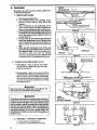
A. INTRODUCTION
- Reduced-Kickback Guide Bar
- Low-Kickback Chain
- Spark Arrestor
-Temperature Limiting Muffler
- Handguards
- Counter-Vibe ® Anti-Vibration System
WARNING
The following features are included on your saw to help
reduce the hazard of kickback, however, such features
will not totally eliminate this dangerous reaction. As a
chain saw user, do not rely only on safety devices. You
must follow all safety precautions, instructions and
maintenance in this manual to help avoid kickback and
other forces which can result in serious injury.
SAFETY
FEATURES
-- Reduced-Kickback Guide Bar, designed with a
small radiustipwhichreduces the size ofthe kickback
danger zone on the bar tip. Figure 5. A ReducedKickbackGuide Bar isone which has been demonstrated to significantly redt'Jce the number and
seriousnessof kickbackswhen testedin accordance
with the safety requirements for gasoline powered
chainsawsas set bythe AmericanNational Standards
Institute,Inc., Standard B175.1-1985.
Low-Kickback Chain, designed with a contured
depthgaugeand guard linkwhichdeflectthe kickback
force and allowwoodto gradually rideintothe cutter.
Figure5. Low-KickbackSaw Chain ischainwhichhas
met thekickback performancerequirementsofANSI
B175.1when tested on a representative sample of
chain saws below 3.8 cubic inch displacement
specified in ANSI B175.1-1985.(American National
Standard for Power Tools- Gasoline Powered Chain
Saws- Safety Req uirements)_
-- Handguard, designed toreduce the chance of your
tefthandcontactingthechaJnifyourhand slipsoffthe
front handlebar.
_-_ PosiUon of f_mnt and mar handlebars, designed
with distancebetween handlesand "in line"witheach
other.The spread and "in line" positionofthehandlebars work together to give balance and resistancein
contmflingthe saw ifkickback occurs.
_,WARNING
Do not operate the chain saw unless the safety
devices or their specified replacements are properly
installed and maintained according to the instructions in this manual. Do not use any othefguide bar
and chain combination that is not equivalent to the
original equipment or not certified to comply with
ANSI B175.1-1985. Failure to follow these instructions
can result in serious injury.
OEFTHGAUG_
ELONGATED
_
• Your saw has been designed with safety in mind and
includesthe following feature_ _s standardequipment:
B, KICKBACK
iii
-
I
i
GU_0_
_
R
_OW'KICK_
S_
Ken'lAIN
FOR_
_KO
[IEFUEC'rs
_T_rl_*
CHAI_ WlTH HIGH
Rgure5
STATE
AND LOCAL REQUIREMENTS.
Your saw Is equipped with a temperature limiting
muffler and spark arresting screen which meets the
requirements of California Codes 4442 and 4443.
Aft U.S. forest !and and the s_tes of California, Maine,
Washington and Oregon require many internal combustion engines to be equipped with a spark arrestor
screen by taw.
J
If you operate a chain saw in a state or locale where
such regulations exist, you are legally responsible for
maintaining the operatingcondition of these parts.
Failure to do so is a violation of the law.See"_park
Arrestor" for maintenance.
D. CARTON
CONTENTS
1. Remove contents from the carton if you have not
done so.
"2. Check the contents against the list below.
3. Examine the items for d_mage. Do not use damaged
parts.
4. Notify your Sears store immediately if a part is
missing or damaged.
NOTE: Iris normalto hear the fuel filter rattle in an empty
fuel tank.
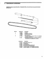
CARTON CONTENTS:
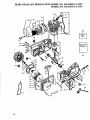
• Key No. __
Qt_
1
Powerhead
2
3
GuideBar
8 oz.can, 2-Cycle
1
1
1
1
-LoosePartsBag (not shown) 1
LOOSE PARTS BAG CONTENTS:
Engine Oil
Operator's Manual (not shown)
4
Handguard
1
5
CapHandguard
1
3
1
2
1
1
6
7
8
9
10
Scmws-Handguard (10x 1")
Screw-Spur (10- 24 x 9/16")
Screw-Spur
Chain
Scrench
Ae
GETTING
READY
1. READ
YOUR
CAREFULLY.
OPERATOR'S
MANUAL
2. HAVE THE FOLLOWING
AVAILABLE:
a.
b.
c.
d.
Protective gloves
Approved, marked fuel container
Onegallon regular unleaded gasoline.
8 oz. (1/2pt.), 2-cycle, engine oil provided with
your unit.
e. Bar and Chain Lubdcant
f. Scrench -- providedwithyouruniLThe longend
of the tool can be used as a slottedscrewdriver.
The small pipe end can be used as a socket
wrench. The larger pipe end can be used to
removethe spark plug.
g. Phillips Screwdriver
Your Operator's Manual has been developed to
help you prepare your saw for use and to understand its safe operation, It is important that you
read your manual completely to become familiar
with the unit before you begin assembly.
S.
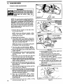
ATTACHING
TH'E HANDGUARD
.........
The Handguard is a protective device designed to
reduce the chance of your left hand contacting the
chain if your hand slips off the front handlebar.
[ ......................
Do notuse" the sawA_ti/_RNINGwithout
the handguard In place. I
Aiways rel_lace
becomes
damaged,
thebroken
handguard
or is otherwise
Immediately
removed.
if it
• Lift and carry the chain saw'by the handlebar,
not by the handguard.
• Keep the handguard securely fastened at all
limes. Check the handguard screws each
time the saw is used.
SCREW
(//10il *)
To install:
1. Align lhe Handguardand HandguardCap aroundthe
handlebar as shown in Figure 6.
2", Fit the mounting pin on the Handguard
the hole in the handlebar. Figure 6.
3. Insert the 3 mounting screws
on the Handg_ard Cap.
Rgure6
....
,,
,
,,
ATTACHING
THE
iiiiiii
SPUR
The spur is a special piece of equipmentdesigned to assist the cutting operation. When
.assembled to the saw, the spur will dig into the
tree or log and:
--relieve
contact pressure adding ease to the
sawing operation.
--allow the saw to be more easi|y rotated or
pivoted into the cut.
To install:
r
1. Remove Bar Clamp Nuts, Bar Clamp Housing
and Guide Bar Plates.
2. Align the spur over the two holes on the bar
clamp side of the saw. Figure 7.
3. Insert the two screws and tighten evenly and
securely.
into the 3 holes
4. Turn each screw.with a Phillips screwdriver a little
"- at a time cloclcwise; until the HandguaEI Cap and
.,
Handguard meet and there is no gap between the
two parts.,
,,
C.
into
BAR
CLAMP
HOUSING
BAR CLAMP
NUTS
Figure 7
,,,,,,,,,
,,,,,,,,,
D,
=ll =.
ATTACHING
ill
i
THE
ii
BAR
AND
CHAIN
JCAUT!ON:JWear
protective gloves when ban.
dling or operating your saw. The chain is sharp
and can cut you even when it is not moving!
• Your saw is equipped with a Reduced-Kickback
Guide Bar and a Low-Kickback Chain.
• Use only the Reduced-Kickback Guide Bar and
Low-Kickback Chain specified for your chain
saw model, when replacing these parts. See
•'Specifications:'
i
completely
Otherwise, zne
can
Do
noton
sta..
rtassembled:
engine
without
bar czutcn
an.d chain
com_
ano
serious
injury guide
can result.
AWARNING
1. Install the inner Guide Plate (has two slots)over
the bar mountingstuds, .
NOTE: Be sure the InnerGuide Plate curves
or flanges toward the saw frame away from
the Guide_Bar. Figure9.
2. Mount the Guide Bar with the slotted end
over the bar mounting studs. Figure 10.
NOTE: Be sure the Guide Bar is positioned
with the round hole below the large slot.
INNER
3. Hold chain with cutters facing as shown in
Figure 11.
4. Place chain over and behind the clutch
drum onto the sprocket.
5. Slide Guide Bar to the rear of the saw as far
as possible,
NOTE; Itmay be necessarytothreadthe adjusting
pin in orout for the guide barto align properly.
6. Fit the bottom of the drive links between
the teeth in the sprocket.
7. Start at the top of the bar and fit the chain
drive links into the groove around the Guide
Bar. Figure 11.
8. Pull the Guide Bar forward until the chain is
snug in the guide bar groove. Figure 12.
9. Install the outer guid e pla_e (one slot). Figure 9
and 12.
10. Slide the Bar Clamp Housing over the mounting
studs and fit the bar adjusting pin (Figure 13) into
the adjusting pin hole in the Guide Bar. Figure12.
11. Replace the Bar Mounting Nuts and tighten finger
tightonly. Tighten Bar Mounting nuts after chain is
tensioned.
NOTE: Thread the bar adjusting pin (Figure 13,14)
in or out as necessaryto fit the adjusting pin in the
hole in the guide bar (Figure 10.)
12. Follow instructions in the "ChainTension"section,
GUIDE
PLATE ( 2 SLOTS)
BAR
STUDS
Figure8
Figure 11
j.... _
GUIDE
SAW
/ OUTER PLATE
PLACE ON OUTSIDE
OF GUIDE BAR)
OUTER GUIDE
BAR PLATE
.... !
(PLACE AGAINST CRANKCAS_
Figure9
Figure 12 "
BAR ADJUSTING PIN
4_ 6
Figure 13
,
E, - CHAIN
TENSION
• Correct chain tension is very important:.
--a
--a
--a
• Chain tensioning procedure:
loose chain will wear the bar and itself.
1. Holdthe t{pofthe GuideBar up and turntheAdjusting
Screw just until the chain does not sag beneath the
Guide Bar.Figure 14.
loose chain can jump off the bar while
you are cutting.
tight chain can damage
break.
the saw and/or
• The chain stretches during
when new. Check tension:
use, especially
NOTE: Turn s_:rew clockwise to tighten tension. Turn screw counterclockwise to loosen
tension.
2..Check the tension by lifting the chain from
the Guide Bar atthe center of the bar. Figure
15.
3. Continue turning the Adjusting Screw until
the tension is correct.
4. Holdthe tipof the Guide Bar up and securely tighten
the Bar Clamp Nuts with the Scrench.
5. Recheck tension.See Figure 15.
• Chain tension is correct When the,chain:
--can be lifted about. 1/8" from the Guide Bar
at a point near the middle of the bar, and
--will move freely around the bar.
each time the saw is used
more frequently when the chain is new
as the chain warms up to normal operating temperature
Figure 15
Figure 14
iiiiiii
F.
i
FUELING
ii
iiii
YOUR
ii
i
iiiii
i
lift
IIIII1[
II
I
IIII
I
i
IIII
IIIIIII
IIIIII
i
iiiii
n I
iiiiiiiii
!
IIIII
I
IIIIIIII
ENGINE
1. FUEL SAFETY
a. Use only recommended fuel mixtures.
b. Mix and pour fuel outdoors and where there are
no s_arks or flames.
c. Use a container approved for fuel.
d. Do not smoke or allow smoking near fuel or the
tool or while using the tool.
e. Wipe upall fuelspillsbeforestarting
engine. f. Move at least 10 feet away ,from fueling site
before starting engine.
g. Stop engine before removing fuel cap.
h. Emptythefueltankbeforestoringthetool.
Iris
recommended thatthe fuel tank be emptied after
each use. If fuel isleft in tank, store sofuel will not
leak.
_i. Store tool and fuelin an area where fuelvapors
cannot reach sparks or open flames from water
heaters, electric motors or switches, furnaces,
etc.
2, FUEL MIXTURE
•
Yourchainsawispowered byatwo.cycleepgine
which requires a fuel mixture of regular unleaded
gasoline and a high quality engine oil specially
made for 2-cycle, air-cooled engines. The internal
design of the 2-cycle engine requires lubrication'of
moving parts.Lubrication is provided when you use
the recommended mixtureof qasoline and oiL
• "Gasoline must be clean _ and not over two
months old. After a short period of time,
gasoline .begins _to chemically break down
and will form compounds that can cause hard
starting and damage in 2-cycle engines.
•
The correct measure of gasoline to oil is very
important.Too much oit in the mixture •will
foul thespark plug.
I _UTION.:_J Too little oil will cause the engine to
overheat and seize.
• Mix the fuel thoroughly in a container since
gasoline and oil do not readily combine. Do not
try to mix fuel directly in the fuel tank°
3, USE THE FOLLOWING ONLY:
_
4. DO NOT USE:
• BIA C)il (Boating
c; Covercontainer
Institute of America)
tighUy and shake forone minute.
d. Slowly remove fuel container cover.
Does not have properadditivesfor_r-cooled,
2-cycleengines and can cause damage.
e. Add remainder of gasoline.
f. Cover container tightly and shake again.
g. Slowly remove fuel container
• AUTOMOTIVE
OIL-
cover.
h. Slowly remove fuel cap. See Figure 16 for location:
i. Fill the tank using a spout or funnel.
•_ Does not have proper additives for 2-cycle
engines and can cause damage.
j. Reinstall the fuel cap securely.
!
5. HOWTO MIX FUELAND RLL TANK
a, Pour 1/2gallonof regular unleaded gasoline
intoan approved, marked container.Do not try
to mix oit and gasoline directly in the fuel tank.
b. Add entire measurez)f engine oil.
Figure 16
G, PAR AHD'cHA!"
LUBB!¢ANi;
• The guide bar and cutting chain require continuous lubrication in order to remain in
operating condition. Lubrication is provided
by the automatic oiler system when the oil
tank is kept filled.
-- Lackof lubricant will quickly ruin the bar and
chain.
--Too
little lubricant will cause overheating
shown by smoke coming from the chain and/or
discolorationof the guide bar rails,
Use Sears Bar and Chain Lubricant #71-36554 I qt. or #71-36556 - 1 gal. or clean SAE 30W oil.
In f_eezing weather, oil will thicken, making it
necessary to thin bar and chain oil with a small
amount of Diesel Fuel #1 or Kerosene. Bar and
chain lubricantmust be freeflowingfortheoilsystem
to pump enough oil for adequate lubrication,
USE:THE
FO'LLowING:
30°F or above -- Lubricant.-30°F - 0°F -Below 0 ° F -*
95%
Fuel
90%
Fuel
lubricant to 5% Diesel
# 1 or Kerosene.
lubricant to t0%'Diesel
#t or Kerosene.
FILL THE OIL
TANK EACH'
IS FILLED.
10
undiluted.
Figure 17
...............
"'
'
HOW TO FILL THE OIL
a. Stop the engine.
b. Turn saw on its side with oil cap up. Figure 17.
c. Loosen cap slowly and w_litfor pressure in the
tank to be released before removing the cap.
d. Fill the oil tank.
e. Replace the oil cap securely.
3. ADJUSTING THE AUTOMATIC OILER
2.
The adjustlng screw k)catadat the b(_:)m of the
saw on the crankcase next to the bar clamp can
be adjusted with the screwdriver end of the
scronch provided with your saw.
a. To increase the - oil flow, turn the adjusting
screw counterclockwise 4b,,_,
b. Todecreasa the oil _flow, turn the adjusting
screw clockwise_'-'jk .
NOTE: The eutomatic oiler can delivermoreoilthan
is required during certaintypes of cutting such as
pruningor debranchingwhichrequirethesawtobe
operated at a high RPM for a long time period. To
avoid runningout ofchain oilbefore_runningout of
'_el, Check the=oil tank:pedodicaUy. Be sure to
readjustthe oiler before returning to types of cutting
that requiregreater lubrication.
4; IMPORTANT POINTS TO REMEM3ER
a. Prime the oil pump on a new saw or a saw that
has been unused for an extended period of
time. Pump the manual oiler slowlyseveral times.
Startthe engine andallo_vthe chaintorun. Stop the
engine and check for an even flow Of oil on the
chain. Repeat this procedure untiloil is visible on
the chain.
b. Fill the oil tank each time you refill the fuel
tank to ensure there wilt be stJfficientoil for the
chain whenever you startand runthe saw.
c. The saw will use about 1/2 tank of chain oil for
each tank of fuel mixture. If less oil is used,
check for a pluggedoilhole in the guide bar.
d- it is normal tor a small amount of oil to appear
under the saw after the engine stops. This is
due to oil drainingfrom the bar and chainwhen
not in use.
USING
A!
YOUR
CONTROL
SAW
DEVICES
THROTTLE
DETENT
Understandingthe controldeviceson yoursaw isan irnportantpartof learninghowtoproperlyand safelyoperate
the unit. Figu're18.
1. The Ignition Switch isa toggle_,witchwhiohismoved
up for the "Start" positionand moved down for the
_'tOl;'
b"Tt,,_T
$TARTISffOP
SWITCH
"Stop" position,
2. The twocosition Choke helpstostartthe saw bycorv
trollingthe air flow tothe fuel system.
3. TheTdggeracceleratesandcontrolsthespeedofthe
engine.
4. The Throttle Lockis a control featurewhichprevents
the Triggerfrom becomingaccidentallyengaged. The
ThrottleLock must be pressedbefore the Triggercan
be activated.
5, The Throttle Detent Button holdsthe ThrottleLock
and Trigger in position while the engine is being
started. Release the ThrottleDetent Button afterthe
engine is startedby lightlysqueezing the trigger.
B. STARTING
INSTRUCTIONS
_,WARNING
Always wear gloves; safety footwear; snug-fitting
clothing; and eye, hearing, and head protection
devices when operating a chain saw.
1. BASIC PROCEDURE
a. Set the saw on fiat ground making certain the
saw chain is free to turn without contacting any
object. F'igure19.Pump the manual oiler slowly
6- 8 times.
b. Move start/stop switch to the "Start" position.
c. Push down on the throttle lock.out, squeezethe
trigger, press and hold down thethrottle detent
button, then slowly release the trigger.
d. Adjust choke according to "Starting Procedure
for Varying Conditions" this page.
e. Hold front handlebarwith left hand & place dght
foot through rear handle to stabilize saw. Figure 19.
f. Pull starter rope quickly, with your right hand.
g. Squeeze throttle to release the throttle lock
allowing engine to idle.
h. Accelerate the engine and allow the chain to
run. Stop engine and check for an even flow of
oil on the chain. Repeat procedure unitl 0il is
visible on the chain.
WARNING
The chain must not move when the engine runs at Idle
speed. Refer to "Carburetor Adjustments;'- for
correction.
i. Stop engine by moving the start/stop switch to
the "STOP" position, Figure 18.
!
__..>_.v_
,\ F'-_.
PosrnoN-,/ | STAmlNG
.OLD
mO_.AN.UE.
xJ_Y'--Z
_'_\
_
I _RANO_AC_R_T
!
FOOTTHROUGH
Figure t9
SWITCH
H&LF
OFF _
,.-
=t I
t_.., Wl
CHOKE
Figure 18
6. The Manual Oiler is placed to be operated by your
right thumb, Use the manualoiler tosupplementthe
automaticoiler:
during a long fellingcut
when cutting intoa log or tree which isgreater in
diameter than the length ofthe guide bar.
-- anytime oil is desired,
2. STARTING PROCEDURE FOR VARYING
CONDITIONS
NOTE: Be sure to follow "1. Basic Procedure" as
described on this page.
a. COLD ENGINE:
1.) Pullchoke to fullchoke position. Figure18.
2.) Pull starterrope until engine attemptsto run.
3.) Push choke until half positionis felt. Figure t8.
4.) Pull starter rope until engine runs.
5.)After 5 second warm up, push choketo the off
position.Figure !8.
t¸
_kWARNING
Avoid bodily contact with the muffler when starting or
using a warm enginelto avoid serious burns.
}
b. WARM ENGINE:
1.)Leave choke at the off position.Figure 18.
2.) Pull starter rope untilengine runs.
c. REFUELED WARM ENGINE AFTER
RUNNING OUT OF FUEL:
1.)Pullchoke to full choke position.Figure 18.
2.) Pullstarter rope until engine attemptsto run.
3.) Push choke to the off position.Figure 18.
4.) Pull starter rope until engine runs.
3. IMPORTANT POINTS TO REMEMBER
a. When pulling the Starter rope, do not usethefull
extentofthe ropeas this cancausetheropeto break.
Do not letthe starter ropesnap back. Holdthe handle and let the rope rewind slowly.
b. If engine floods, let the unitset for a few minutes,
then repeatstarting procedbre usingthe half-choke
position.
c. For cold w_.atherstarting, allowenginetowarmup
(1-2min.)at the haJf.t::hoke
position, then movechoke
to the dosed position. Do not cut with the chokeat
the "full" or "half" position.
11
,
,
,,,,,,,,,
,,,,,,
,
,
,,,,
ii
i
iiiii iiiiiiiiii
i iii
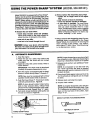
USING THE POWER SHARP®SYSTEM
i i i|
Model 35_.356101 is equipped with a Power Sharp®
System that will perform approximately 80% of the
sharpening necessary for t;,a saw chain. The Power
Sharp ® System utilizes a built-in gdnding stone to
sharpen the cuttertop plates and set depth gauges. As
the built-in sharpener is used, the cutter side plates
graduallywillbe altered. Aboutevery3rd to 5thtime the
Power Sharp® Systemis used, hand filing is required
to correct the cutter side plates and depth gauges.
• Sharpen
--wood
Wood
about
the saw chain when:
chips become small and powdery.
chips made by the chain should be
the size of the teeth of the chain.
--saw cuts to one side.
--saw has to be forced through the cut.
ICAUTiON: 1 Ai_ays wear -'
y..vvu_
...... v,,'hOn _'''";"_
the chain. The chain can be sharp enough to cut
you, even when it is too dull to cut wood.
Am
AUTOMATIC
(MODEL 358.356101)
i
i
ii i ii
ii
ii
i iii i
• Always replace the sharpening stone when
• --sparks are no longer seen at full adjustment
--only 1/4 inch of stone is remaining
--stone has become cracked or damaged.
--a new chain is installed. The used stone
will be worn to the shape of the old chain
and can cause excessive wear to a new
chain. Replacement chain comes supplied
with Stone Cartridge Replacement #69099.
Refer to"Replaceor Remove the Stone and
Carrier Assembly" in this section.
• Always remove the sharpening stone if a conventional chain, is-substituted for the ,Power
Sharp s Chain. See instructionsfor removing the
Stone Cartridge in this section. Use replacement chain #7I-3638• Foliow "ChainSha_rpeni,_g'
in the Maintenance section•
SHARPENING
1. Stop the engine.
2. Place the saw on a solid, flat surface and
make sure that the chain will not contact
any object.
3. Adjust the chain with correct tension. Refer to
"Chain Tension"
IMPORTANT: The chain must be tensioned
correctly for proper sharpening to occur•
!
4. Start the engine and operate athalf to three/
quarters throttle during Steps"5 through 8".
NOTE: Saw must be runningathalf to three/
quarters throttle before knob is pressed.
5. :Push the Power Sharp ® __Knob down slowly :
until fully pressed down. Figure20.
NOTE: If stone should contact chain before
knob is fully pressed down, release knob
and turn knob counterclockwise until condition does not exist. Repeat Step "5" again.
6. Turn knob slowly clockwise until sparks can
be seen as shown in Figure 20.
NOTE: Proper sharpening occurswhen a light
flow of sparks is seen. Improper sharpening is
shown by a heavy flowof sparks or no sparks
7. Release knob and turn one additional "click'
clockwise.
NOTE: It is important to turn the knob onl_
one "click" each time the knob is pressed.
More turns will result in making the chain dul
instead of sharp.
8. Press knob firmly against chain and hold fo=
10-15 seconds or until sparks can no long el
be seen.
9. Release knob and stop the engine.
i0. Inspect
chain cutters.
NOTE: A properly sharpened cutter will sho
grinding marks across its entire width. Figul
21.If cutters do not appear sharp or burrs a[
seen on the top front of the cutters, repel
Steps "7-8".
INSPECT
CUTTERS FOR GRINOING MARKS
SPARKS ARE SEEN HERE
TOP VIEW OF CUTTER
Figure 21
Figure 20
12
i]
i
B.
HAND
,,,,,,,.,, ,,,,,,,,,,,,,,
,,,
,,,,,,,,
.............
,
,
FILING
Sharpen theside platesand depthgaugesby handafter
every3rd to 5th time the PowerSharp_ System is used.
Items Required:
Gloves
5/32" dia. file
file holder
SUPPORT
-_
iF-_
D FILl
OF FILE HOLDER
ON TOP OF CUTI'ER
flat file
vise
screwdriver
FLAT SIDE
_DEPTH
;_
L_
N
AUGE
NOTE: If abrasive materials such as rocks, nails,
sand or dirt are contacted by the chain, the side
plates should be checked more often. Damage
to the cutters caused by abrasive materials
usually results in discoloration spots where the
chrome has been worn away. Cutter side plates
should be filed until these spots are removed.
1. Stop the engine.
2. Adjust the chain for proper tension, See "Chain
Tension:'
3. Clamp the bar in a vise to hold the chain
stead','. Do not ctamp the chain.
•
SIDE PLATE
, ,i
i
i,ii
Figure22
HOLD FILE
HOLDER LEVEL
WITH THE 22 °
GUIDE MARK
PARALLEL TO
GUIDE BAR
Figure23
NOTE: Work at the midpoint of the bar, moving'the chain forward with a screwdriver as
each cutter is filed.
t
4. Support the square rod on the file holder (with
5/32" round file) on cUttei"top plate. Figure 22.
5. Holdthe file holder lever(900)withthe22° guidemark
parallelto guide bar. Figure 23.
6. File from inside toward outside of cutter in
one direction only -- 2 or 3 strokes pep side
plate edge should be enough. Figure24.
NOTE: Avoid hitting the top edge of the cutter_ when filing the side plate.
Figure 24
_IDE
PLATE
SIDE PLATE
li
!
!
,,
PROJECTION,_"-
-ll32 "
7. Maintain a 1/32" side plate projection.
25,
"t-'-','
_,JI
"-_"
c.
TOP /l
PLATE
OF CUTTER
k_l 22°
-- -.
ii
,u
, i
iiiiii iii
i
lib
'1IIIIIIIlflll
III
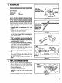
ASSEMBLY
!_ Remove Ca.,buretorCover and Bar Clamp Housing.
2. Remove the two screws which hold cartridge
assembly to crankcase. Figure 26.
3. Discard old assembly.
4. Insta!l new cartridge assembly.
NOTE: Be careful
fall out.
_
Figure 25
"..... '...............
CARRIER
t
.........
TOP
e
9. File depth gauges according to instructions on
page 18.
AND
_
IL
Figure
8. File all side plates on one side of'the chain,
then move to the other Side of bar and file remaining side plates.
STONE
132"
not to let the Slid# Button
5. Reinstall Carburetor Cover and Bar Clamp Housing.
I
ASSEMBLY
•
I
................,figure
26"
13
•
:
........
i
TYPES
ii
I
i
iii
ii
HIIHIIIIIIIIIIIII
I
II
I
BASlC
CUTTING
guide barcan cause the chain to dig into the object and
stop the chain for an instant. The resuit is a lightning
fast, reverse reaction which kicks the guide bar up and
back toward the operator, ff the saw chain is pinched
along the top of the guide bar, the guide bar can be
driven rapidly back toward the operator. Either of these
reactions can cause loss of saw control which can
result in serious injury.
2. UNDERSTAND
REACTIVE FORCES
Pinch-Kickbackand Pull-in occur when the chain
is suddenly stopped bybeing pinched, caught, or
by contacting a foreign object in the wood. This
resultsin a reversalofthe chain force used tocutwood
and causesthe saw tomovein the Oppositedirectionof
chain rotation.Eitherreaction can resultin lossofcontrql and possible serious injury.
= Pinch-Kickback
--occurs when the chain, on top of the bar issuddenly
stopped when the top of the bar is used for cutting.
--rapidly drives the saw straight back toward the
operator.
• Pull-In--can occur when the chain on the bottom of the
bar is suddenly stopped.
--pulls the saw rapidly forward.
ii
B.
TREE
i
FELLING
I I
III
II
ij
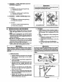
3.
PROCEDURE
Practicecuttinga few small logsusingthefollowing technique toget the "feel" of usingyour saw beforeyou begina
maior sawingoperation.
a. Accelerate the engine to full throttle just before
entering the cut by squeezing the throttle trigger.
b. Begin cutting with the spur against the log.
Figure27.
c. Keep the engine at full throttle the entire time you
are cutting.
d. Allow the chain to cut for you; exert only light
downward pressure. If you force the cut, damage to
the bar,chain, or engine can result. "
e. Release the throttle trigger as soon as the cut is
co mp
' _t. ed, ai1_n
if"you runt]h_
..... g theenn_nnt_idle
.... u.......
saw at full throttle without a cutting load, unnecessai3
wear can occur to the chain, bar, and engine.
t
f. Donot put pressure on the saw atthe endof thecu.
to avoidlosingcontrolwhen the cut is complete.
g. Stop the engine before setting the saw down aftea
cutting.
/(
: _' /-/'.
BEGIN CUTTING WITH THE
AGAINST LOG,.
F_ure27
i ¸
"
ii
iii
TECHNIQUES
1. PLAN YOUR SAWING OPERATION CAREFULLY IN ADVANCE
a. Clear the work area. You need a clear area all
around the tree where youcan have secure
footing.
b. Study the natural conditions that can cause
the tree to fall in a particular direction:
1.) TheWIND direction and spe_d.
2.) The LEAN ofthe tree.
3.) WEIGHTED with BRANCHES on one side.
4.) SurroundingTREES and OBSTACLES.
c. Look for decay and rot. If the trunk is rotted,
it could snap and fall toward the operator.
t4
i,
TECHNIQUE
1. IMPORTANT POINTS.
a. Cut wood only. Do not cut metal, plastics,
masonry,non-wo_ buiiomgmatedais,et_ Donor
useyoursawto pryor shoveaway limbs, rootsor
otherobjects.
b. Stop the saw if the chain strikes a foreign
object. Inspect the unit and repair or replace
parts as necessary.
_
c. Keep the chain out of dirt and sand. Even a
small amount ofdirt will quickly dull a chain and
.....
thus, increase the possibilityof kickback.
-.
A KICKBACK WARNING
Kickbackcan occur when the moving chain contacts an
object at the upper pc rtion of the tip of the guide bar or
when the wood closes in and pinches the saw chain in
the cut. Contact at the upper portion of the tip of the
-
III
OF CUTTING
IIIHIIIIIIIIIIIIII
A.
--
d. Check for broken or dead branches whi(
could fall on you while cutting.
e. Make sure thereis enough room for thetree
fall. Maintain a distanceof 21/2tree lengthsfro
the nearest person or otherobjects.Engine noi=
can drown out warning call.
f. Remove dirt, stones, loose bark, hall
staples, and wire from the tree where cu
are to be made:
g. Plan to stand on the up-hill side when cl
ting on a slope.
h. Plan a,,clear retreat path to the rear ar
diagonal to the line of fall. Figure 28,
2, FELLING SMALL TREES -- LESS THAN
6" IN'DIAMETER
a. If you know the direction of fall:
1.) Make a single felling cut on the side away
from the directionof fall.
2.) Cut alithe waythrough.
3.) Stop the saw, put it down, and get away
quickly on yourplanted retreat path.
b. If you are not sure which way the tree will fall,
use the notch method described for felling
iarge trees.
CUT
I
HORIZONTAL
Figure 28
A_,WARNING
DONOTCUT:
near electrical wires or buildings.
if you do not knowthe direction of tree fall.
-- at night since you will not be able to see well.
m during bad weather _ strong wind, snow, rain,
etc.
3.
FELUNG LARGE TREES m 6" DIAMETER
OR MORE
_
The notch method is used to cut large trees. A
notch is cut on the side of the tree in the desired
direction of fall. After a felling cut is made on the
opposite side of the tree, the tree will tend to fall
into the notch_
OFF_
WARNING
NOTE: Before the felling cut is complete, drive
wedges toopen up the cutwhen necess_y to controlthe directionoffal Use weedor plasticwedges
but never metal, to avoid kickback and chain
damage.
a. Make the notchcuL Figure30.
b.
. C.
Make the felling cut on the opposite side of the
notch about 2" higher than the bottom of the
notch.
Leave enough uncut wood between the felling
cut and the notchto form a hinge. Figure 31.
NOTE: The hinge helps to keep the tree from
twisting and falling in the wrong direction.
d*
Use a wedge ifthere is any chance that the tree
will not fall in the desired direction.
DON'T
Check the wind.
Don't cut down wind.
PUT YOURSELF
,
Stay on the uphill side of the terrain to avoid the
tree rolling or sliding downhill after it is felled.
NOTE: If the tree has large buttress roots, remove before making the notch. Cut into the buttresses vertically, then horizontally. Figure 29.
1.) Cut the bottom of the notch first, through
1/3 of thediameter of the tree.
2.) Complete the notch by making the slant
cut.
3.) Remove the notchof wood.
Figure29
e.
f.
Be alert for signs that t_hetree is ready tofall:
1.) cracking sounds
2.) widening of the felting cut
3.) movement in the upper branches.
As the tree starts to fall, stop the saw; put it
down, and get away quickly on your planned
_retreat patho
g- Be ex_emely cautious with partially fallen trees
thatmay be poorlysupported.When a treedoesn't
fall completely, set the saw aside and pull down
the tree with a cable winch, block and tackle or
tractor.To avoid injurydo not cutdown a partially
fallen tree with yoursaw.
iN THESE
Check the
"Don't cut on lean side.
15
u iii iiiiiii
C.
i
iii
i
BUCKING
Bucking is the term used for cutting a fallen tree
to the desired log size.
1. IMPORTANT
ii
iiiii
ISTCUT
PRESSURESIDE _
4-_
POINTS
a. Cut only one log atatim e.
b. Cut shattered wood very carefully. Sharp
pieces of wood could be flung toward the
operator.
c. Use a sawhorse to cut small logs. Never
allow another person to hold the log while cutting and never hold the logwith your leg or foot.
d. Give special attention to logs under strain to
prevent the saw from pinching. Make the first
cut on the pressure side to relieve the stress on
the log. Figure 32.
e. Do not cut in an area where logs, limbs and
roots are tangled such as in a blown down
area. Drag the logs intoa clear area before cutting by pulling out exposedand cleared logs_
first.
f. Make the f_rst bucking cut 1/3 of the way
through the log and finish with a 2/3 cut on
the opposite side. As the log is being cut, it
wilt tend to bend. The saw can become
pinched or hung in the log if you make the first
cut deeper than 1/3 of the diameter of the log.
2. TYPES
i i 111111
iii
1
OF CUTTING
4-,--
_
2NDCUT
L
Figure32
UNDERCUT
Figure33
WEDGE USED TO
HOLD CUT OPEN
USED Figure33.
/
-- Overcutting - begin on the top side of the
log with the spur against the log: exert light
pressure downward.
.- Undercutting - begin on the under side of the
log with the top of the saw against the log;exert
light pressure upward. During undercutting,
the saw will tend to push back at you. Be prepared for this reaction and hold the saw firmly
to maintain control.
Figure 34
•
AWARNING
" _
_I
Never turn the saw upside down to undercut. The
saw cannot be controlled in this position.
If saw becomes pinched or hung in a log, don't try to
force it out. You can lose control of the saw resulting
in injury and/or damage to the saw. Stop the saw,
drive a wedge of plastic orwood into the cut until the
saw can be removed easily. Figure 34, Restart the
saw and carefully reenter the cut. To avoid kickback
and chain damage, do not use a metal wedge. Do
not attempt to restart your saw when it is pinched or
hung in a log.
BUCKING--WlTHOUTA
,
|.
IstCut
US,N
_WARNING
3.
I.
SUPPORT
a. Overcutwith a 1/3 diametercut.
b. Roll log over and finish with an overcut.
ANOTHER
LOG AS A SUPPORT
.I.-A-.i
:
12ndCutl
"._,?'_
"_
"
I
Figure35
[,1
B
lst_
2nd
cut
cut
t,I
_'_
Figure 36
16
a,t
c=
4. BUCKING-- USINGANOTHERLOGAS A
" SUPPORT(Figure35):
a. In areaA:
1 .) Undercut 1/3 of the way through the log.
2.) Finish with an overcut.
Do not stand on the log being cut. Any portion can roll
_WARNING
!
causing loss of footing and control.
b.. In area B:
1.) Overcut, 1/3 of the way th;ough the log.
2.) Finish with an undercut.
5. BUCKING-•
USING A STAND (Figure
36,):
a. tnareaA:
1.) Undercut 1/3 of the way through the log.
2.) Finish with an overeut.
b. Inarea B:
,)
1 .) Overcut 113of the way through the log.
2.) Finish with an undercut.
,,,,111
i i
O.
,
ir
DEBRANCHING
AND PRUNING
AWARNING
Never climb into a tree to debranch or prune. Do not
stand on laUders, platforms, a log or in any position
which can cause you to lose your balance or control of
the saw.
DEBRANCHING
MAINTAINSECUREFOOTING
,,,
• Work slowly, keeping both hands on the saw
with a firm grip. Maintain secure footing and balance.
• Watch out for springpoles. Use extreme caution
when cutting small size limbs. Slender material can
catch the saw chain and be whipped toward you or
pull you off balance.
• Be alert for springback. Watch out for branches
that are bent or under pressure as you are cutting
to avoid being struck by the branch or the saw when
the tension in the wood fibers is released.
• Keep a clear work area. Frequently clear branches out of the way to avoid trippingover them.
i_
USE COMMON SENSE
o
PRUNING
a. Limit pruning to limbs shoulder height or
below. Do not cut if branches are higherthan
your shoulder. Get a professional to do the
job.
b. Refer to Figure38 for the pruning technique.
1 .) Undercut 1/3 of the way through the limb
near the trunk of the tree.
2.) Finish with an overcut farther out from the
trunk.
3.) Keep out of the way of the falling limb.
.4.) Cut the stump flush near the trunk of the
tree.
_ILWARNING
Be alert for and guard against kickback. Do not allow
the moving chain to aontact any other branches or
objects at the nose of the guide bar when debranching
Orpruning. Allowing such contact can result in serious
injury.
........
a. Always debranch a tree after it is cut down.
Only then can debranching be done safely
and properly.
Remove small limbs
with one
b. Leave the larger lower limbs to supportthe
tree as you work.
c. Start at the base of the felled tree and work
towards the top, cutting branches and
limbs. Remove small limbs with one cut. Figure 37.
d. Keep the tree between you and the chain.
Cut from the side of the tree opposite the
branch you are cutting.
e. Remove larger, supporting branch_s with
the 1/3, 2/3 cutting techniques described in
the bucking section.
f. Always use an overcut to cut small and
freely hanging limbs. Undercutting can cause
limbs to fall and pinch the saw,
FIRST PRUNING CUT
Figure 38
17
•
°11
""
i i-
i
ii
_=_ iii
:
.
ii
•
i
i
iii
iii iiiiiiiii
i
MAINTENANCE
ii
i
i i
i
A good maintenance program of regular inspection and care will increase the service life and help
to maintain _he safety and performance of your
saw.
• Make all adjustments or repairs (except carburetor adjustments) with:
spark plug wire disconnected
B engine cool as opposed to a unit that has
just been run.
IH
• Check the saw for loose bolts, screws, nuts,
and fittings on a regular basis. Loose fasteners can cause an unsafe condition as well as
damage to your saw.
Have all chain saw se_ice with the exception of the
items listed in the maintenance section of this man_ILWARNING
1
ual performed by your Sears Service Center.
iiiii
..........GUIDE
AND
A.
BAR
CHAIN..........
Increase the service life of your Guide Bar and
Chain by:
--Using the saw propedy and as recommended
in this manual.
•--Maintaining correctChain Tension. See "Chain -.
Tension".
_. Proper lubrication.See 'Bar and Chain Lubricant".
Regular maintenance as desc.'ibed In this section.
1. CHAIN
MAINTENANCE
• Sharpen the chain when:
--wood chips are small and powdery. Wood
chips made by the saw chain should be
about the size of the teeth of the chain.
--saw has to be forced through the cut.
--saw cuts to one side.
ii ii iiii
sue_,T
.ou.D
FLATFILE
SLIDE
OF
HOLDER
_ILE
Rgure 39
PARALLEL
30° MARKT.o
_
CUi-tER4
, ...............
==°°'=°="/7
'KE
Rgure4O
ICAUTION:I Always wear gloves when handling
the chain. The chain is sharp enough to cut you
even though it is too dull to cut wood.
a. SHARPENING
i
TOP PLATE
SIDE PLATE
Rgure 41
INSTRUCTIONS
Ite_ns required:
Gloves
7/32" dis. file
6" file holder
Medium Flat File
Depth Gauge Tool
Vise
i:) Stop engine and disconnect spark plug,
2.) Adjust
"Chain
the chain
Tension':
Figure 42
DEPTH GAUGE
TOOL'
for proper tension. See
GAUGE
3.) Work at the midpoint of the bar, moving the
chain forward by hand as each cutter is
filed.
.
t8
) Sharpen cutters.
a.) Position flat side of file holder (with
7132" round file)on cu_er top plate and depth
gauge. Figure 39.
b. ) Hold the fite holder level with the 30 ° guide
mark parallel to the center of the chain.
Figure 40.
c.) File from inside toward outside of cutter,
straight across, on forward strokeronly.Use
2 or3 strokes per cutting edge. Figure 40,
d. ) Keep all cutters the same length. Figure 41.
e. ) Fileenoughtoremoveanydamagetocutting
edge(side & top plate) of cutter. Figure 41 •
f. ) File 72SG chain to meet specificationsshown
in Figure 42..
Rgure43
HOOK
&HGLE
t
_f
•
_fOO MUCH
HOOK
ANGLE
.02f'
' 50UARED
OFF COF_NER
l
COF_NER
_nOUNOEO
RIGHT WAY
WRONG WAY
Figure 44
WARNING
Maintain the proper hook angle according to the
manufacturer's specification for the chain you are
using. Improperhookanglewigincreasethe
chanceof
kickback which can result in serious injury
Figure 42 & 44
5. )CorrectDepthGauges
2. GUIDE
a.)'Placedepthgaugetool(Catalog
No.
71.36557)
overeachcutterdepth
gauge.
Figure43.
b.) Filelevelwith
thefiatfife ifdepth
• Conditions which can require guide bar
maintenance:
gauge is higherthan the depth gauge
tool.
c. ) Maintain rounded frontcorner of
depth gauge with a fiat file. Figure 44.
--saw
cuts to one side
--saw
has to be forced through a cut
inadequate oil supply to bar and chain.
'e Check the condition of the guide bar each
time the chain is sharpened. A worn guide
bar will damage the chain and make cutting more difficult.
NOTE: The very top of the depth gauge should be flat with
lhe front half rounded off with a fiat file.
• Replace the guide bar when:
_WARNING
Depth gauge toO! Is required to Insure proper depth
gauge. Rlingthedepth gaugetoodeep will increase the
chance of kickback which can result in sedous Injury.
--the inside groove of the guide bar rails is
worn.
--the guide bar is bent or Cracked.
• Use only the Reduced-Kickback Guide Bar
specified for your saw in "Specifications"
for replacemenL
a. Remove the guide bar to service.
• b. CHAIN REPLACEMENT
1.) Use onlythe Low-Kick Chain specified for
your saw in "Specifications,
for replacement chain.
2.) Replace the chain when cutters or links
break.
b.
Clean oil holes at least once for each
five hours of operation.
c.
Remove sawdust
groove periodically
a wire. Figure45.
d.
Remove burrs by filing the side edges
of the guide bar grooves square with a
flat file. Figure46.
3.) See your Sears Service Center to replace
and sharpen individual cutters for matching your chain.
4.) Always have a worn sprocket replaced by
your Sears Service Center when installing
a new chain to avoid excessive wear to the
chain.
I'"REMOVE SAWDUST
_
BAR MAINTENANCE
" e.
Restore square edges to an uneven rail
top by filing with a flat file. Figure39.
,
CORRECT
GUIDE BAR
GROOVE
"
WORN GROOVES
Figure45
li[ll
ii
i
B. SPARK
i
from the guide bac
with a putty knife oc
FILE EDGES
. SQUARE
,
.
"
.
Figure 46
i
i
ARRESTOR
•
ii
.
iiiii ii ii
HI
i
i_
illlll,i
i
i
q
I,,HI ,,I,I,
I
SPARK ARF
•
Carbon deposits build up on the spark arnestor,as the saw isused and must be rernovedto
avoidcreating a fire hazard or causingengine damage.
•
Replace the sparkarrestor if breaks occur.
•
Keep the spark arrestor clean at all times,
Clean:
HEAT SHIELD
\
IIHII
--as required
---at leastonce for each 25-30houm of operation.
Items requir_,3_:
wire brush,318"wrench _
i ,,,ll
a. Disconnectthe spark plug wire.
b. Remove the heat shield. Figure 36.
c. Remove thescreen from the diffuser.
d. Clean the screen w,i_ha wire brush or replace if
breaks are found.
e. Reassemble pads.
19
--
C.
=
STARTER
Y'l
i
i
•
i
i
iiiiiiiiiiiii
ul
i|lllllll
., _
,
ROPE
• Replace a starter rope that breaks.
_I_WARNING
Always wear eye protection when servicing the starter rope. The recoil spring
beneath the pulley is under tension. If the
spring pops out serious Injury can
result.
€
/
/
/
/
/
//--_-"
MEDIUM--_
NOTE: The recoil spring, located beneath the
pulley, is Under tension. If spring pops out, it
will require considerable time and effort to
reinstall. For this reason, you may want to let
your Sears Service Center handle this repair.
If you do try to repair the starter rope and the
recoil spring pops out, take the unit to your
Sears Service Center.
1. Remove the four screws
"__
housing. Fi,gum 48.
|Q!I
/
i
LONG
Figure48
TURN PULLEY .....
rNTERCLOCKWtSE
TO RELEASE
TENSION
on the side of the
NOTE: Notice the different lengths of the
screws and their proper locations while
removing the screws.
NOTCH
Figure 49
u.oERSIDE
_-,_-'------
.
Remove the fan housing.
3. if the starter rope is not broken, release the
spring tension by pulling about 12 inches of
rope from the pulley and catch the rope in
the notch as shown. F_jure 49,
PULLEYSCREW
PULLEYRATCHET
_
I"O_IOEPUU.EY HOLE
;CREWORIVER
NOTE: The tension on the starter spring will
be released if the rope has broken.
4. Turn the pulley counterclockwise
until thespring tension is released. Rgure49.
5. 'Remove the pulley screw in the center of the
pulley. Figure 50.
6. Lift the pulley carefully while gently twisting it
counterclockwise
_
, and remove the
.old rope.
_7,
Move away, from.the .fuel _tbhk-and melt the -, " ....
end of the new rope to go into the pulley.
8, Allowthe metted end todriponce;then whilethe rope
is stillhot,pull the melted end througha clean rag to
obtain a smooth, pointedend.
9. Insert one end of the rope through the handle and
secure with a knot. Leave 3/16" pigtailbehind knot.
Figure 49 (inset).
10. Feed the rope through the housingand
the
round sta_er hole. Rgure50.
LE
•
_
Figure 50
14. Set the pulley into the housing; push it do_
and engage the spring.
15. Replace and tighten the pulley screw.
16. Pull out t2 inches of:repe and catch the rope
the notoh ir_ the pulley, Ftgure51.
17, Turn the pulley 3 complete turns clockwi_
winding up the spring.
18. Hold the pulley and pull the starter rope
the full extent of length and let the rope
wind slowly.
19. Replace fan housing with the fourscrews
their proper Iocatibn.
=,l
i
=
11. Guide rope inside pulley,then through the topside
pulley hole by pushing the rope from the underside
hole with a small round object such as a Phillips
screwdriver.See insert, Figure 50. r
2O
12. Wrap rope counterclockwise _
around
pulley ratchet and tuck loose end back under
rope leaving a 3/8-1/2 inch tail. Pull tightly around
ratchet.Figure 50.
13. Rewind all the rope onto the pulley, turning
counterclockwise
_
P'_
NOTCH
Figure 51
i
D.
i
CARBURETOR
i1.,,,,,,,,i i i
AD3USTM
ii
i i
i
iI
,,,,,,,,,i ,i
ENlrS
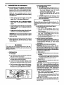
• The carburetor has been adjusted at the factory for
sea level conditions. Adjustments may become
necessary if the unit is used at significantlyhigher
altitudesorjfyounoticeanyofthe following conditions.
r
Engine dies or hesitates when itshould accelICAUTION: I Permanent damage will occur to any
2-cycle engine if incorrect carburetor adjustmerits are made,
•
If the unit will not operate properly after making
these adjustments, take the unit to•your Sears
Service Center.
A_,WARNING
The chain may be moving during most of this pro_.
eedure. Wear your protective gear and observe all
safety precautions.
!, PREPARATION
a. Stop engine.
': _?b.Use a fresh fuel mixture with proper gasoline/oil
ratio. See "Fueling YourEngine".
c. Placethe sawon asofid,flatsurfaceand make sure
the chain will not contact any object.
d. Locate the three (3) carburetor adjusting screw
openingsto therightofthe airfiltercover.F_jure 52.
e. Startthe engine and allowengine to idle3 minutes
to warm up. The engine must be at operating
temperature for proper adjustments to be made.
IDLE
SPEED ADJ. SCREW'
F_gure52
iiiiiii
iiii
bw
--Chain moves when the engine runs at idle
speed. See "2. Idle Speed Adjustment:'
-- Loss of cuffing power which is not corrected by
a|r filtercleaning, "See "5. High Speed Mixture
Adjustment."
i i
2. IDLE SPEED ADJUSTMENT
a. Allow engine to idle.
AdjustIdle Speed Screwuntilenginecontinues|o
run withoutstallingandwithout the chain moving
Turn screw clockwise _
to increase
engine speed if enginestallsor dies.
Turnscrew counterclockwise It.._
to slow
engine down and!or to keep the chain from
turning.
c.-No further adjustments are necessary if the
chain does not move at idlespeed and if performance is satisfactory.
NOTE: Be sure to propedy p_,_i)are the saw as
describedin "1. Preparation" below,beforemaking
any adjustments.
-- Saw will not idle. See "2. Idle Speed Adjustment" and "3. Low Speed Mixture Adjustment."
i
J
_WARNING
Recheck idle speed after each adjustment below. The
.,chainmustnotmoveatidle
speed to avoid serious
injury.
3. LOW SPEED MIXTURE ADJUSTMENT
a. Allow engine to idle.
b Turn the Low Speed Mixture Screw slowly
clockwise _
until the RPM starts to drop.
Note the position.
c. Turnthe Low Speed Mixture Screw counterclockwise _
untilthe RPM speeds up and sta_s
to drop again• Note the position.'
d. Set the Low Speed Mixture Screw at the m_d_int between the two positions.
4. ACCELERATION ADJUSTMENT
Ifengine dies or hesitatesinstead ofaccelerating, turn
the Low Speed Mixture Screw 1/16ofatum at atime
counterclockwise _
until you have smooth
acceleration.
5. HIGH SPEED MIXTURE ADJUSTMENT
ICAUTION: I Adjustments as small as 1/16 of a
.turn can affect engine performance, It is Important totum the screw only 1/16of a turn per adjustment and test the performance of the saw before
making further adjustments.
a. Make a test cut.
b. Adjust the High Sl_._lMixture S_'ew 1/16ofatum
as follows:
--CloCkwise _
ifsawsmokesorlesespower.
-- Counterclockwise _
if the saw has speed
out of the cut but lackspower in the cut.
c. Repeat test cut.
d. Continue 1/1.6of a turn adjustmentsuntilthe saw
runs smoothly in cut.
JCAUTION: I A too lean high speed setting (clockwise _
adjustment)willcauseenginedamage to any 2-cycle engine fror_ overheating and
lack of lubrication. Never set the high speed mixture screw so far clockwise _
thatyouhave
high engine speed but lack power while cutting.
An effective approach follows:
Turn screw counterclockwise
_until
engine loses power while cutting.
Then, turn screw clockwise _
in 1116of a
turn increments only until the engine has
power while cutti_l.
NOTE: If the unit will not operate propedy after
makingthese adjustments,takethe unittoyourSears
Service Center,
21
iiii
-E •
iii
CLUTCH
I
DRUM
AND
ii
i i
i
i
i iiii
ii
iiii
SPROCKET
_WARNING
Do not start engine without Guide Bar, Chain, and Bar
Clamp Housing completely assembled. The clutch can
come off without the guide bar and chain completely
assembled and serious injury can result. Do not loosen
and spin the clutch off the crsp_haft with a powertool
Theclutch shoes and drum can separate causing the
clutchtoviolentlyfly
apart and sedous injury can
result.
• Clean the clutch, drum/sprocket and surrounding area daily during heavy use of the
saw. Check to see that the clutch drum turns
freely arid smoothly.
• Inspect the drum/sprocket regutarly for wear.
A worn sprocket will make the chain run erratically
and will shorten the life of the bar and chain. Figure 53.
e Replace the drum/sprocket whenever a new
• Take the saw to your Sears Service Center for
full clutch inspection and service after each
100 hours of operation, it is recommended that
you do not try to service the clutch or drum/sprocket yourself unless you are a competent small..
engine mechanic and have the proper clutch service tools. Proper disassembly and repair of the
clutch is extremely important to the life of the
engine and the safety of the operator.
• Clutch maintenance is required when:
--the chain0continues to turn while engine
idles after the idle speed screw has been
adjusted to its capacity.
--slippage occurs dudng a cuL
--a chattedng noise occurs dudng cutting.
chain is installed in order to gain the fulllife expectancy of the chain. Use the following procedure:
CHAIN WEAR ON DRIVE SPROCKET
(Model358.3560911
Figure_3
i
F.
AIR FILTER
• A dirty air filter:.
--reduces
cutting power
--increases
fuel consumption
• Clean the Air Filter,
--frequently,
especially under very dusty
conditions.
--always
after 10 tanks of fuel mixture or 5
hours of operation whichever is less.
fCAUTION:I Never operate the unit without th(
air filter in placeto avoid engine damage,
Items Required: soft bristled brush, such as
• paint brush.
1. Clean off the .carburetor cover and the are_
around it.
2. Close choke to prevent dirt from entering th_
carburetor,
3. Remove t_e carburetor cover. Figure 54.
4. Remove the air filter carefully.
5. Soak the _lter in soap and water.
ICAUTION:J Do not use gasoline or other flam
•:-_ _. bleliquid to clean the filter to a_toidcreating a
hazard.
6. Brush away al! dust and debris from the filter
7. Allow filter to dry.
8. Brush away all debris from surfaces whict
were covered by the carburetor cover.
9, Replace filter and carburetor cover.
Figure 54
H,ii iHi
G.
, , u,,,
__
IIIII
iiiii..........
i
STORAGE
When your saw is to be stored for over 30 days,
always:
1.
2.
22
&
Drain fueltank in asafe manner..S_e "FuelingYour
Engine-- Fuel Safety"
Start engine and allow to run at i(_lespeed until the
engine stops.
4.
5.
NOTE: This wit! remove most of the fuel from the
fuel _%_'tem.
7.
8.
Drain oil tank.
6.
i
i
H.
..,...I
ICAUTIONilWear
protective gloves when h
dling the chain. The chain is sharp and can
you even when it is not moving.
Remove, clean, and dry the bar and chain.
Store the chain in a container filled with oil to _:
vent rust.
Apply a coating of oil to the entire surface of the
and wrap it in heavy paper, cloth or plastic.
Clean the Outsidesurfaces of the engine.
Store the saw in a dry place, out of the react
chiidren, and away fromwherefuel vapors can re;
open flames from hot water heater, electric motor
switches, furnaces, etc.
i
H.
iiiii
MAINTENANCE
iiiiiiiiiiiii]
• i iiiiiiiiiiii
i
.......
AccE--SSORIES
Available through your nearest Sears Store, Catalog Sales Office ,or Servk_eCenter, but may not be furnished
with your s .ap,.
Key No.
1
2
3
4
Catalog No.
71-36565
71-36524
71-36526
71-36557
71- 36867
71-3639
Catalog No.
71-36407
71-36627
71-36555
71-36554
71-36556
71-36370
71-30583
Description
FileGuide
File-5/32" dia.-Twin Pack
File-7/32" dia.-Twin Pack
Depth GaugeTool
"
Xtra GUARD ®Chain- Oregon® (72SG -70) - 358.356091
(requires 7!32"alia.file)
Power Sharp® Chain - Oregon® (76PS-66)- 358.356101 (includesStoneCartridge Ass'y.)- not shown
Description
--------
Spark Plug-Champior_CJ-8Y
Carrying Case
2-Cycte Engine Oil
Barand Chain Lubricant(gallon size)
Bar and Chain Lubricant(quart size)
Lo-Kick_ Guide Bar- 18"-358.356101 (not shown)
Lo-Kicl_ Guide Bar- 20" - 358.356091 (not shown)
23
i
i/jl
ii1'
I
i1,1
!.
TROUBLE
SHOOTING
........
ii
iiiiiiii
i, _,
i ,,
WILE Nor START
CAUSE
REMEDY
1. ignition Switch off,
2. Fuel tank empty.
3, Spark Plug not firing.
1.
2`
3.
4.
i
,
'Move switchto "Start:'
Fill tank with conrsctfuet mixture.
Install new plug,
Check for dirty fuel filter;siean. Check for
kinked or split fuel line; repair or replace.
5. See Starting instructions.
6. Contact your Sears Sendce Center.
.-
4, Fuel not reeching ce_uretsr.
5. Engine flouded.
6. Compre-_ion low.
...,,
ENGINE WILL Nor IDLE
PROPERLY
, ,,,,,,,,,,,,,
1. Idle speed set too low.
1. Adjust idle speed screw clockwise to
increase speed.
2. Adjust idle speed screw counterclockwise to
reduce speed.
3. See Carburetor Adjustments.
4, Contact your Sears Service Center.
5. Coelact your Sears Service Center.
2, Idte speed set teo high,
3, Low speed screw requires adjustment•
4. Crankshaft seals Wom.
5. Compression low.
,,,
ENGINE
iii
i ,,_1 •
CHART
TROUBLE
ENGINE
i
WILL Nor
1,
2.
3.
4.
5.
ACCELERATE,LACKS.
POWER OR DIES
IN THE CUT
.,,
,..,.w
Carburetsr requiresadjustment.
Air flJteris dirty.
Spark plug fouled,
Carbon build-up an exhaust ports,
Low Compression
1.
2,
3,
4.
5.
See Carburetor Adjustments.
Clean or replace air filter.
Clean or replace SparkPlug'and regap.
Contact your Sears Service CenteL
Contact y_ur Sears Service Center.
, ,,,....,,.,,
ENGINE SMOKES
EXCESSIVELY
1, O{1rich fuel mixture.
ENGINE RUNS HOT
OIL INADEQUATE FOR
BAR AND CHAIN
LUBRICATION
1. Empty fuel ta:nkand rsfill with correct fuel
mixture.
2. Push Choke in,
3. See Carburetor Adjustments,
4. Clean or replace air filter.
5. ContaCt your Sears Service Center,
2.
3.
4.
5.
Choke parfiaily on.
Highspeedn_'dle requiresadjustment.
Air filterdirty.
Crankcaseieak.
1.
2.
3.
4.
Fanhousingdirty,
FuelMixtureincorrect.
HighSpeed Mixturesettoolow.
Carbonbuild:uponsparkarrestorscreen.
5- Spark Plug incorrect.
6. Carbonbuiid-uponexhaustports.
1.
2.
3.
4.
5.
6.
Clean fan housing.
See Engine Fuel Mixture.
See Carburetor Adjustments.
Clean spark arrestor screen.
Repfacewithoormctplug.
ContactyourSeamServ_eCenter.
1.
2.
3.
4.
I.
2.
3.
4.
FUloiltank.
Adjust oiter.
Contact you_Sears Sen/ice Center.
Remove bar and clean.
Oil tank empty.
Impmpedyadjuaiedoiler.
,
Oil pump or oil filter clogged.
Guide bar oil hole blocked.
', ,,,,,J,........
IDLE SPEED
,
,
,,,,,,,,,
CHAIN DOES NOT MOVE
"WHEN ENGINE,S
• ACCELERATED ""
" "AtNC Tr RS'0R
CUTS ROUGHLY
•
,,
CHAIN STOPSWITHtN
THECUT
CHAIN CUTS AT
AN ANGLE
;
1." Chain tension too tight..
L
!2. Carburetor mquires adjustment.
• 3.: Guide bar r=ils pinched.
4. Clu_chstipping:
1.
2.
3.
4.
, ,,,,,,,,,
..........
,
1, Chain cutter tops not filedflat.
2`. Guide bar burred or bent; rait uneven.
3. Clutch slipping,
1. Cuttersdamagedononestde.
r
2. Chain dull on one side,
3. Guide bar bent, or worn.
WBRA IN.EASES
ON
1. Vibration isolators worn
2, Vibration iso!atom ripped, tom separated
or out-of-round.
24
SeeChaJn Tension.
SeeCarburetorAdjustments,
Repair or replace,
,
ContactyoursearsServiceCenter,
,,,,
1. Cuttem damaged after striking foreign
matedaL
2. Chain tension incenrect or loose.
3. Chain wear due to contact with dirt, sand or
metal object inwood.
4. Sprocket worn.
5, Cutters dull, improperly sharpened; depth
gauges too high,
, ,,,,,,
, ......
1• "see Carburetor Adjustment_
2. Contact your Sears Service Center.
1. Idle speed requkesadjustment.
2. Clutch requires repair,
,,,u ..........................
1. Contact your Sears Service Center.
2. See Chain Tension.
3, Resharpen or replece chain.
4. Contact your Sears Service Center.
5. See Chain Sharpening Instrustions.
t
, ,,,,,,
1. SeeChainSharpeninglnstructions.
2. Repair or reptace Guide Bar.
3.
Contact your Sears Service Center.
1. Resharpen until all cutters have equal angles
and lengths.
2. Re.sharpen tmti! alt cutters have equal angles
and lengths.
3. Replace guide bar.
1. Gentact your Sears Sentice Center.
2, Contact ,yourSears Service Center.
,,_
,llllllll
iI i I
d.
ii
i
i
MAINTENANCE
ii
i lll
,i
,m,,,
,,,,,,,,,,,,,,,
..............
CHAFIT
=
Visualinspection(cond_on,leaks)
x
X
Completemachine
Clean
Throtiletrigger,safetythrottlelock.stopswitch
x
Checkoperation
I- x"
"x
CleanFelt
x
Filtarin fueltank
Replacefelt+-- when cloggedor dirty
Fuel tank
Clean
.
x
Chainoiltank
Clean
Chainlubrication
Check
X
Inspect( sharpness,wear,damage)
X
X
Check chain tension
X
X
x
Saw chain
Sharpen -- whendull
Inspect(wear, damage)
x
I
Clean when chain is rem_,d for
maintenance
!Guide bar
X
Lubricatesprocket nose .
Deburr
Replace-- whenwornor damaged
Chainsprocket
Check
Clean
Ai[fllter
..........................
Replace-- when wornoi damaged
Exhaust ports
Clean
Cylinder fins
:Clean
x
x
x
x
Check idleadjustmentCarburetor
chainmust notturn
x
Readjustidle-- whenchainturnsat idle
Spark plug
All accessible,screwsandnuts
(notadjusting screws)
Vitiation mounts
x
g
Replace-- whenfouledor damaged
rRetJghten
! inspect(tears, rips, separation,
¢uFof-round)
X
X
Replace-- whenwornor damaged
inspect
x
Spark arrestor screen
Replace-- when worn or damaged._
25
NOT[5
26
NOTES
27
SEARS CHAIN SAW REPAIR PARTS-MODEL
NO. 358.356091-3.7/20"
MODEL NO. 358,356101-3.7/18"
19
49
23
36
,oI
44
I
64
29
,25
26
14
36
16
62
46
I01_
37
28
SEARS CHAIN SAW REPMR
KEY
NO,
I
2
3
4
5
6
7
8
9:
10
11
12
13
14
15
16
17
18
19
20
21
22
23
24
25
26
27
28
29
30
31
32
33
34
35
36
PART
NO,
530-039()95
530-023817
STD522525
530-015434
530-024476
530-001626
530-001722
530-015468
530-015123
STD600603
530-030054
530-042066
530-024329
530-042051
530-042053
530-015364
530-010720
• 530-024392
530-024391
STD522505
530-024385
530-024384
*530-019097
STD600603
530-024232
530-028487
530-024388
530-024387
530-032051
530-015354
530-030039
530-042056
530-069233
530A012067
*530-019129
PA_TS-MODEL
NO. 358.356091-3.7/20"
MODEL NO. 358.356101-3.7/18"
DESCRIPTION
Flywheel Ass'y. (Incl. #2)
Starter Dog Spring
Screw
Screw
Spur
Washer
Flywheel Nut
Screw
Washer
Screw
Crankcase Sealant
Recoil Spring Inner Disc
Recoil Spring Bushing
Starter Recoil Spring
Recoil Spring Outer Disc
Screw
Fan Hsg. Ass'y,
Muffler Shield
Muffler Cover
Screw
Spark Arrestor Screen
Muffler Diffuser
Crard_sha ft Seal
Screw
Air Baffle
Starter Pulley
Muffler Back Plate
Muffler Body
Crankshaft Bearings
Thrust Washers
Bar Stud Replacement Kit
Starter Rope Handle
Rope Kit
Cylinder
Cylinder Gasket
Crankcase Ass'y. (Incl.
#23,29,31 & 50 o/_ tl-ds
page;also includes from
page 31, #22,30,37.&
KEY
NO.
PART
NO.
37
38.39
40
41
42
43
44
530-015365
530-030073
530-015195
530-025933
530-024492
530-001624
530-039096
530-010626
45
46
47
48
49
STD580008
530-015366
530-039097
530-039071
530-039102
50
52
53
530-010444
530-024334
530-039093
54
55
56
57
58
59
60
61
62
63.
530-015425
530-023661
STD600603
STD511007
530-023732
530-039099
530-039115
530-023575
530-024858
530-031107
530-069190
64
530-066648
101
530-026468
DESCRIPTION
Screw
Spark Plug (CJ-8Y)
CUp
,Piston Ping
Crankshaft and Rod Ass'y,
Screw
High Tension Lead
Piston Ass'y. Kit (Incl, #40
and pin)
Flywheel Key
Screw •
Spark Plug Boot
Spark Plug Connector
High Tension Lead Ass'y.
(Incl.
#43,47, & 48)
OilCap Ass'y.
High Tension Lead Clamp
ignition Module (incl. #49
59)
Screw
Lead Clamp
Screw
Screw
Toggle Switch
Switch Lead
(3/16)
(i/4)
Ignition Switch Nut
Start/Stop Plate
Scrench
Gaske_Kit (*IndicatesContents)
Operator's
Manual
" Fan Hsg. Decal
43)
530-010696
530-010699
*Indicates
Contents
358,356091
358,356101
of Gasket
Kit #691tP_
29
SEARS CHAIN
SAW REPAIR
PARTS-MODEL
NO. 358.356091-3.7/20"
MODEL NO. 358.356101-3.7/18"
MODEL
358.356101
3.7/18"PS
(ONLY)
39
49
45
"18
102
46
101
47
"-- 19
48 •
CARBURETOR ASSEMBL]
PAR_F NO. 530-035094
103
34
/
22
\
23
4O
12
43
32
44
42
12
3O
SEARS CHAIN SAW REPAIR pARTS-MODEL
MODEL
KEY
NO.
1
2
3
4
5
6
7
8
9
10
11
12
13
14
15
16
17
18
19
22
23
24
25
26
27
28
PAinT
NO,
530-025919
STD511003
530-010347
*530-019107
530-024229
*530-019101
530-015194
530-012056
530-024383
530-035094
*530-019099
530-015462
530-024373
530-024376
530-025258
530-024349
530-015414
530-069216
530-091878
*530-019122
530-010286
530-012055
530-024357
530-032053
530-025469
530-015245
NO. 358.3-56091-3.7/20"
NO. 358.356101-3.7/18"
KEY
NO.
DESCRIPTION
Choke Rod
Screw
Bracket & Bushing Ass°y.
Carb. Adaptor Seal
Adaptor
Gasket
Screw
Handle Brace
Choke Wire
Carburetor Ass'y.
Gasket
Screw
Isolator
Isolator Cup
Spacer
Carb. Seal Bracket
Screw
Line Kit
Fuel Pie'k-Up Ass'y.
Seal
Fuel Tank Ass'y_ (Incl.
#19 & 34)
Right Rear Handle
Throttle Lock
Bushing Throttle Lock
Trigger Spring
Screw
29
31
32
33
34 36
37
38
39
40
.41
42
43
44
45
46
47
48
49
I01
PART
NO.
DESCRIPTION
* 530-019104
530-032059
530-024699
530-015168
530-010331
530-026013
530-015369
530-024482
530-024976
530-025486
530-024378
530-012054
530-015403
530-015393
530-015608
530-024877
530-024548
530-019123
* 530-025895
530-025425
Seal Adaptor
Bushing
Throttle Link
Screw
Fuel Cap Ass'y.
Throttle Trigger
Screw
Knob
Carb. Cover Ass'y.
358.356091
358.356101
Throttle Lock Spring
Left Rear Handle
Screw
Screw
Screw
Retaining Ring
• Air Filter
Gasket
Cylinder Shield
Adjusting Knob
(358.356101)
530-026872
530-026871
530-025586
102
103
Starting Instructions Decal
358.356091
358.356101
Sharpening Instructions Decal (358.356101)
Replacement
Bar & Chain
Deca!
358.356091
358.356101
530-026883
530-026882
*Indicates
Contents of Gasket Kit, Key No. 62, p. 29.
_ll
II[lllllll[I]]]ii
I Ii
ul.,i,iiiHiii
UII
Ill
.II.IN
[llll
i i
.
,,,,i
Jill
i lilll
|]llllll
.ill
I
li,.lll
illNil
II llllllllllllllll
..ll i
Carburetor Assembly
Part No. 530-035094
KEY
NO.
PART
NO.
51
530-035102
52
+530=035015
53
530-035123
54
530-035119
55
530-035101
56
530-0351 t5
57
530-035099
58
0530-035109
59
+ 530-035113
60
+ 530-035069
61
+ 530-035111
62
530-035106
63
+ 530-035118
64
+ 530-035097
65
530-035125
66 :
530-035105
67
_'530-035107
DESCRIPTION
Throttle Valve
Screw
Fitting
Throttle Ret. Spring
Throttle Shaft Ass'y.
Screw
Fuel Pump Cover
Fuel Pump Gasket
Fuel Diaphragm
Inlet Screen
Circuit Gasket
Inlet Needle Valve
Mtrg. Lever Spring
Throttle Lever (Outer)
Throttle Lv. Bushing
Throttle Stop
Choke Friction Ball
KEY
NO.
68
69
70
71
72
73
74
75
76
77
78
79
80
81
82
83
84
PART
NO.
+530-035022
+530-035124
+530-035096
530=035126
+530-035116
+o530-035108
+530-035114
530-035098
+530-035021
530-035104
530-035103
530-035121
530-035117
530-035122
530-035202
530-035112
530-035127
DESCPdPTION
Choke Friction Spring
, Check Valve Screen
Screen Retaining Ring
Circuit Plate Ass'y.
Circuit Plate Screw
• Mtrg. Diaphragm Gasket
Mtrg. Diaphragm Ass'y.
Mtrg. Diaphragm Cover
Mtrg. Cover Screw Ass'y.
Choke Valve ,
Choke Shaft Ass'y.
Idle Screw Spring
Idle Adj. Screw
Hi & Lo Needle
Mixture Needle Retainer
Carb. Gasket Kit (olndieates
Contents)
Carb. Repair Kit (+Indicates
Contents)
31
SEARS CHAIN SAW REPAIR PARTS-MODEL
NO. 358.356091-3.7120"
MODEL NO. 358.356101-3.7/18"
102
21
See page 29, #36
Repair
Chain
Kit
52
I
72
54
22
55
43
44
14
/
5
6
.7
58 _
65
27
3_
I01
61
33
56
63
47
48_
57
•60
I
MODEL
IIIllll
358.356101
3mlS"PS (Only)
69
See page 29, #36
%
32
SEARS
KEY
NO.
1
2
3
5
6
7
8
9
10
11
12
CHAIN SAW REPAIR PARTS-MODEL
NO. 358.356091-3.7/20"
MODEL NO, 358.356101-3.7/18"
PART
NO.
STD511003
530-024351
530-024348
530-015357
530-032049
530-048069
530-048071
530-024465
530-024353
530-010291
530-010466
530-024352
13
14
15
16
17
18
19
20
21
22
530-026246
530-025428
*530-023373
530-024347
530-024225
STD511005
530-023356
STD583037
530,023357
530-024467
530-015509
530-069185
23
24
25
26
27
28
*530-019103
530-002615
530-019029
530-015418
530-023358
530-069062
29
30
32
33
34
35
36
37
38
39
530-024677
530-021038
530-023699
530-022197
530-010289
530-024676
530-021031
530-002464
530-024691
*530-024345
*Indicates
Comems
DESCRIPTION
Screw
Bracket
Manual Oile, Lever
Thrust Washer
Clutch Bearing
Dnnn & Sprocket Ass'y.
358.356091
358.356101
Clutch Plate
(358.356091)
Clutch Spring
Clutch Ass'y. (Incl.
#9,11 & 12
358.356091
358.356101
Shoe Clutch
ClutchSpider
358.356091
358.356101
Oiler Rod Boot
Manual Oiler Rod
Crankcase Side Isolator
Screw
OilPump Cap
-Oil Pump Retainer Ring
Oil Pump Plunger
Handguard Cap
Screw
Oil Vent Replacement
Kit
Gasket
Oiler Tubing Nut
Oil Pump Quad Ring
Washer
Oil Pump Spring
Oil Pump Service Kit
Auto/Manual
(Incl#17,
18,19,24,25,26,27,30,
32,33,34,37,38,39,
40,41,& 42)
Oil Line Protector Spring
Discharge
Oil Line
Diaphragm Spring
Button and Pintle Ass'y.
Oil Line Pick-Up Ass'y.
(Incl. #29,35 and 36)
Oil Pick-Up Line Weight
Oil Line
Sleeve - 1/8 Tubing
Oil Pump Vent Filter
Oil Pump Diaphragm
of Gasket
KEY
NO.
40
41
42
43
4.4
46
47
48
•49
50
51
52
53
54
PART
NO
*530-019102
530-025987
530-015297
530-015422
530-025925
STD510810
530-024399
530-010727
530-010741
530-025924
STD600603
530-024466
530-022258
STD522510
71-36867
71-3639
55
56
57
58
59
60
61
62
63
64
65
66
71-30583
71-36370
530-015362
530-024373
530-024376
530--025044
530-015445
530-015361
STD581018
530-025414
-530-015385
530-015391
530-048071
67
68
530-o15484
952-004746
69
70
530-025421
530-069099
71
72
STD511005
530-052079
101
102
-
530-026468
530-026849
530--026550
DESCRIPTION
Gasket
Pump Cover
Screw
Tubing Nut
Inner Guide Bar Plate
Screw
Oiler Cover Plate
Bar Clamp Hsg. Ass'y.
(Incl. #59,62,63 & 64)
358.356091
358.356101
Outer Guide Bar Plate
Screw
Handguard
Handlebar Ass'y.
Screw
Chain
358.35609.!
358.356101-Inel.
#70
Bar
20" SN-358.356091
18" SN-35_.356101
Isolator Mount Spacer
Front Handlebar Isolator
Front Isolator Cups
Bar Adj. Pin
Flange Nut
Spacer
E Ring Adj. Screw
U-Clip
Screw
Screw
Clutch Drum & Adaptor
Ass'y. - (7 Sptine
v
3/8P)-(358.356101)
Plate Clutch (358.356101)
-FMmLng Rim Sprocket (318P
- 7 Tooth) (358.356101)
Slide Button
Stone & Carrier Ass'y.
(Incl. #69) - (358.356101)
Screw(358.356101)
Chain Repair Kit
(358,356101
Only) Op-tional
Bar Clamp Hsg. Decal
Handguard Decal
Chain Tensioning Decal
Not Shown
Kit, No. 63, p.29.
33
NOTES
34
QUICK REFERENCE PAGE
Read and follow all Safety Rules, Precautions and Operating Instructions.
Failure to do so can result in serious personal injury.
SAFETY RULES AND PRECAUTIONS
PREPARATION
1.
2.
3.
4.
5.
..................................
page
3-5
3-5
.. .........
Wear personal protective gear -, gloves; safety footwear; snug fitting clothing; and eye,
hearing and head protection•
Check for worn, loose; missing or damaged pads and repair or replace as necessary.
Check the chain for sharpness and tension.
Keep children,bystanders and animals a minimum of 30 feet (10 meters) awayfrom the w0rkarea.
plan your sawing operation carefully in advance.
-.
FUEL AND OIL
1.
2.
3.
4.
5•
6.
Eliminate all sources of sl_arks or flame where fuel is mixed, poured, or stored,
Use 16 parts regular, unleaded gasoline to 1 part air-cooled, 2-cycle engine oil.
Use gasoline not over 2 months old.
Mix and pour fuel in an approved, marked containerand in an outdoor area. _
Move a minimum of 10feet (3 meters) away from fuel and fueling site before starting engine.
Fill ""
,,.,e O_1
" ta..._
_" each time the fuel tank is refueled.
STARTING
1.
2.
3,
4.
THE ENGINE
5.
6,
7.
8.
11
THE
SAW .........................................................
14
Cut wood on!y.
Accelerate the engine to full throttle before entering the cut.
Begin cutting with the spur up against the logo
Cut only at full throttle.
Release the trigger as soon as the cut is completed•
Stop the'engine before setting the saw down after cutting.
MAINTENANCE
1.
2.
3.
4.
........................................................
Set saw on flat ground with the saw chain free to turn without making contact with any object.
Hold front handlebar with left hand and place right foot through rear handle to stabilize saw.
Use less than the full extent of the rope per pull.
Release the throttle detent button afterengine starts, allowing engine to idle.
• OPERATING
1.
2.
3.
4.
5.
6.
9 lo
...............................................................
18
Adjust or have the carburetor adjusted if the chain moves when the engine idles.
Disconnect
spark plug before performing maintenance except for carburetor adjustment,
r
Check the guide bar for wear each time the chain is sharpened.
Clean the ai_ filter frequently and always after 10 tanks of fuel mixture or 5 hours of operation,
whichever is less.
Clean spark arrestor at least once for each 25-30 hours of operation•
Take the-saw to your Sears Service Center for full clutch inspection after each 100 hours
of operation.
Drain fuel tank in a safe manner before storing the unit for 30 or more days.
Store saw in a dry place out of the reach of children.
........
, ,,,,,,
_
-
%
1
WATCH OUT FOR
KICKBACK
NOT USE
THE SAW WHEN
•IT NEED_EPAIR
NEVER USE THE SAW
WHEN TIRED
J
USE A FIRM GRIP
WITH BOTH HANDS
,
35
TheModel Numberwill be found underthe handlewith the Serial
Number.Alwaysmentionthe Model Numberwhenrequestingservice or repair parts for your Chain Saw.
All parts listed herein may be ordered from any Sears
and most Sears. Stores.
WHEN
ORDERING
REPAIR
PARTS,
FOLLOWING INFORMATION AS SHOWN
operator's
manual
ALWAYS
GIVE
IN THIS LIST.
THE
1.
The PART NUMBER
3.
The PART DESCRIPTION
2.
The MODEL NUMBER
4.
The NAME OF ITEM
Chain Saw
358.356091-3.7120"
358.356101-3.7/18"PS
MODEL NO.
358.356091-3.7/20"
358.356101-3.7/18"PS
Service Center
If the parts you need are not stocked locally,
• electronically
transmitted
to. a Sears Repair
center-for handling.
When you
from Sears
something
can offer :..
your order will be
Parts Distffbution
buy merchandise
you get an extra
that nobody else
Sears Service.
Across
town or across th_
country, Sears Service follow_
you,
providing
trustworthy
competent" service technician.,
using
0nly Sears spe.cifie(
factory parts.
How
Repair
to Order
Parts
SEARS SERVICE
i
S(.aI
5302066648-5-21188
s,_ebue
and
Co., Chieagx),llt
,
h
60684
U.S,A.
PRINTED
INU.t