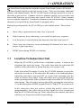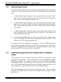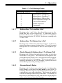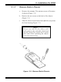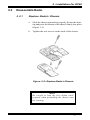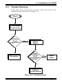
1
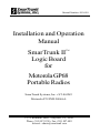
Manual Number: 502-4501 Installation and Operation Manual SmarTrunk II Logic Board for TM Motorola GP68 Portable Radios SmarTrunk Systems, Inc. • ST-865M3 Motorola P/N PMLN4066A 23278 Bernhardt Street • Hayward, CA. 94545 Phone: (510) 887-1950 • Fax: (510) 887-4011 Internet: [email protected] Warranty Policy A ll SmarTrunk products are guaranteed to meet or exceed published performance specifications and are warranted against defects in material and workmanship for a period of two (2) years from date of purchase. Third party equipment such as radios, power supplies, antennas, etc., carry the factory warranty of their respective manufacturers. All warranty repairs must be performed at the SmarTrunk factory in Hayward, California, or other factory authorized repair depot. Any unauthorized repair attempted by the customer, alteration or modification of the equipment, damage by external sources, or removal or alteration of the serial number label or date code, will void the warranty. Specifically excluded from this warranty are batteries, fuses, lamps, and damage caused by lightning, power surges, or mechanical abuse. Equipment for repair may be returned to the factory without prior written authorization; however, a note must be sent with the packing list briefly describing the nature of the defect. Repairs must be shipped freight prepaid and will be returned freight prepaid. Shipments should be directed to: SmarTrunk Systems, Inc. ATTN: Repair Department 23278 Bernhardt Street Hayward, CA 94545, U.S.A. Quality Policy Statement SmarTrunk Systems, Inc., has a continuing objective to enhance our worldwide reputation as a supplier of products and services which meet or exceed customer requirements. With personal commitment and pride in everything we do, all officers, managers, and employees will work together for continuous improvement in the processes and procedures which affect SmarTrunk’s product quality and customer service. SmarTrunkTM is a Trademark of SmarTrunk Systems, Inc. Motorola Manual Number 68P04370J43 CONTENTS INTRODUCTION ......................................... V I I 1 OPERATION .............................................. 1 1.1 Landline To Subscriber Call .................... 1 1.2 1.3 Receiving A Call ..................................... 2 Call Routing Codes For Subscriber Initiated Calls ......................................... 2 1.3.1 1.3.2 1.3.3 1.3.4 1.3.5 1.3.6 1.4 Subscriber To Landline Call ................................ 3 Subscriber To Subscriber Call ............................. 3 Fleet Dispatch (Subscriber) To Group Call ........ 3 Conventional Mode ............................................... 3 Mobile Operator Call ........................................... 4 Emergency Call ...................................................... 4 Originating A Call ................................... 4 1.4.1 1.4.2 1.4.3 1.4.4 1.4.5 1.4.6 Store And Send Dialing ........................................ 5 Memory Speed Dialing ......................................... 6 Programming Memory Speed Dial Numbers ...... 6 Redial ..................................................................... 7 Priority Call Override ........................................... 7 Clear Channel Alerting ......................................... 8 1.5 Call Termination ..................................... 8 1.6 Radio-Kill ............................................... 9 2 OPERATING MODES ............................... 11 2.1 Subscriber ID Numbers/Paging Code Numbers ............................................... 11 2.2 Conventional .........................................14 3 INSTALLATION ........................................ 15 3.1 Disassemble Radio................................15 3.1.1 3.1.2 5/1/96 Remove Battery .................................................... 16 Remove Radio Chassis ........................................ 17 iii Model ST-865M3 SmarTrunk II™ Logic Board 3.2 Installation of the Logic Board ...............18 3.3 Reassemble Radio ................................19 3.3.1 3.3.2 Replace Radio Chassis ....................................... 19 Replace Battery and Antenna ............................ 20 3.4 Trouble Shooting ...................................21 3.5 Portable Radio Programming ...................22 3.5.1 System Tone .......................................................... 22 4 LOGIC BOARD PROGRAMMING .............. 23 4.1 Entering The Program Mode ...................23 4.2 Programming Feature Descriptions ........23 4.2.1 4.2.2 4.2.3 4.2.4 4.2.5 4.2.6 4.2.7 4.2.8 4.2.9 4.2.10 4.2.11 4.2.12 4.2.13 iv Number of Trunking Channels ........................... 24 Primary Code ....................................................... 26 Secondary Code .................................................. 26 Priority Subscriber Enable ................................. 26 Five Digit Access Code ....................................... 27 Return To Radio Default Values ......................... 28 Trunking System ID Number .............................. 28 Automatic PTT Mode ........................................... 29 Emergency Call Override ................................... 29 Clear Channel Alerting Mode ............................ 30 Radio-Kill ............................................................. 30 Memory Speed Dial Programming ..................... 30 Conventional Operating Mode .......................... 31 CONTENTS Tables Table 1-1 • Call Routing Codes ........................................................ 3 Table 1-2 • Dialing Modes ................................................................ 5 Table 2-1 • ST-852M Programming ............................................... 13 Table 2-2 • Mobile Programming .................................................... 14 Table 4-1 • Programming Options Summary Table .......................... 25 Figures Figure 3-1 • Slide Battery Latch ...................................................... 16 Figure 3-2 • Slide Battery Cover ..................................................... 16 Figure 3-3 • Remove Radio Chassis ................................................ 17 Figure 3-4 • Exploded View of Radio ............................................. 18 Figure 3-5 • Replace Radio's Chassis .............................................. 19 Figure 3-6 • Troubleshooting ........................................................... 21 Appendixes Appendix A • Programming Worksheet ........................................... 33 Appendix B • Motorola P/N • HLN9247A & HLN3083A SmarTrunk Systems, Inc. • ST-868M50 Cross Reference Chart ............................................ 35 v Model ST-865M3 SmarTrunk II™ Logic Board (This page left blank intentionally) vi INTRODUCTION T he ST-865M3 SmarTrunk II Logic Board is a microprocessor based radio trunking logic board designed for use with Motorola GP68 Radio. The ST-865M3 implements SmarTrunk II, an efficient radio channel allocation protocol. The SmarTrunk II Logic Board controls all radio functions including channel scan, PTT, and all transmit and receive audio. In combination with the ST-852M SmarTrunk II Digital Trunking Controller, the Logic Board provides a complete multi-channel digital access radio trunking system. The ST-852M is the heart of the SmarTrunk II system. Programming and operation is performed by the System Operator/Manager. Many of the programmable features of the ST-865M3 require information unique to a specific system. These system specifics can only be obtained from the System Operator/Manager. In addition to SmarTrunk II trunking operation, the ST-865M3 has a conventional operating mode. This mode allows the radio to operate as a conventional two way radio on the programmed radio channels. Conventional mode can be disabled by the dealer. The ST-865M3 offers the user the following features: • • • • • • • • • • • Store and send dialing 10 number memory speed dial (user programmable) Last number re-dial Different ringing tones to distinguish the type of call Clear channel alerting tells subscriber when a channel is available Ten levels of priority call override Two trunking modes: radiotelephone and fleet dispatch Capability of operation on SmarTrunk and conventional non-trunked radio channels Automatic acknowledgment eliminates wasted airtime Five digit security code for dealer programming Remote Radio-Kill to disable illegal and non-paying customers This manual is presented in four sections: • Section 1, Operation, describes operational features. • Section 2, Operating Modes, describes the operating modes available in a SmarTrunk II system. • Section 3, Installation, provides instructions for programming of radio frequencies and installation of the ST-865M3 logic board. • Section 4, Logic Board Programming, provides the installing technician instructions to configure the ST-865M3 by programming the resident EEPROM. Please read the entire manual before proceeding in order to take advantage of all the advanced features. vii Model ST-865M3 SmarTrunk II™ Logic Board (This page left blank intentionally) viii 1 • OPERATION S ubscribers already familiar with the original SmarTrunk system will find the SmarTrunk II digital system just as easy to use. There are also many additional features and enhancements. The ST-865M3 begins trunking operation as soon as the radio is powered on. Channel selection, transmit control, receiver audio, and other radio functions are all under the control of the ST-865M3. Radio channel access is tightly controlled. Unauthorized transmission and monitoring of trunking channels is not possible by SmarTrunk II equipped radios. During keypad operation, the ST-865M3 provides audible alerts. These alerts are: a. Short chirp is generated each time a key is pressed. b. High frequency beep indicating a successful keypad entry sequence. c. Low frequency beep indicating that improper data has been entered. d. Three long low frequency beeps indicating all channels are busy or improper keypad operation. e. DTMF tones during DTMF over-dialing. 1.1 Landline To Subscriber Call When the ST-852M is called from a telephone system, it answers the telephone line with two beeps. The caller then dials the subscriber ID number of the subscriber or group that they are trying to call. If the subscriber ID number is valid, the ST-852M attempts to reach the subscriber over the air. If the subscriber ID number is for a radiotelephone subscriber unit that is powered OFF or is out of the operating, area the caller will hear a busy signal. If the subscriber unit is powered ON and is in the operating area the caller will hear a ring back and the ST-865M3 will start ringing. The subscriber answers the call by pressing the asterisk key (*) on the microphone DTMF keypad (Push-To-Talk (PTT) is not pressed). If the subscriber does not answer within the mobile answer time (programmable), the caller will get a busy signal for a few seconds and then the ST-852M will hang up. If the subscriber does answer, the caller will hear two beeps and can then begin talking. 9 Model ST-865M3 SmarTrunk II™ Logic Board 1.2 Receiving A Call The subscriber is alerted to an incoming call by ringing of the subscriber equipment. This alerting takes four forms, related to the type of incoming call. a. A long single high frequency ring is generated by the logic board, then a low frequency dual tone ring is generated by the controller. This indicates an incoming landline call. b. A short double high frequency ring is generated by the logic board, then a low frequency dual tone ring is generated by the controller. This indicates an incoming call from another SmarTrunk II radio subscriber. c. A short single high frequency ring is generated by the logic board, then a double beep is generated by the controller. This indicates a manually dialed group call. d. A short single high frequency ring is generated in the calling radios logic board, then a double beep is generated by the controller. This indicates a (PTT) dispatch group call. For items a and b, the subscriber must press * on the DTMF keypad to answer the incoming call (Push-to-talk (PTT) is not pressed). For items c and d, the subscriber may communicate with other members of the group by pressing PTT (no answer action is required). 1.3 Call Routing Codes For Subscriber Initiated Calls Call routing codes are used for initiating a call from a subscriber to the appropriate destination. Call routing codes are commonplace in PBX telephone systems. For example, to place a call to an outside telephone line through a PBX, a call routing code of typically 0 or 9 must be dialed first. The SmarTrunk II system operates in a similar fashion, however, the call routing code is placed at the end of the calling sequence. The following table describes all the call routing codes. The subscriber needs to be familiar only with the call routing codes that apply to their application. 10 1 • Operation Table 1-1 Call Routing Codes Routing Code 1 2 3 4 5 9 0 1.3.1 Destination Subscriber to Landline 1 Subscriber to Landline 2 Subscriber to Subscriber Fleet-Dispatch/Group Call Conventional Mode Mobile Operator Emergency Subscriber To Landline Call Routing codes 1 and 2 give the subscriber access to telephone line one or two respectively. A subscriber may be restricted from line 2, or there may not be two telephone lines connected to the ST-852M. In this case, routing code 2 is not valid. 1.3.2 Subscriber To Subscriber Call Routing code 3 allows the subscriber to place a call to another subscriber or group of subscribers. The call is routed through the ST-852M and does not use the telephone system. 1.3.3 Fleet Dispatch (Subscriber) To Group Call Routing code 4 allows the subscriber to place a call to the subscriber’s own group. This functions as though the subscriber had used routing code 3 with the subscriber ID number of the subscriber’s own group. When automatic PTT is enabled, operation of the PTT initiates a group call to the subscribers group using routing code 4. 1.3.4 Conventional Mode Routing code 5 selects conventional mode. In this mode, radio channel switch positions not used by SmarTrunk II trunking channels may be programmed and used for conventional two-way radio operations. This feature is enabled or disabled during initial setup of the radio. Availability of this mode is determined by the radio dealer supplying the radio, or the System Operator/Manager. 11 Model ST-865M3 SmarTrunk II™ Logic Board 1.3.5 Mobile Operator Call Routing code 9 calls the subscriber that is preprogrammed as the Mobile Operator. This functions as though the subscriber had used routing code 3 with the subscriber ID number of the Mobile Operator. The Mobile Operator is programmed by the System Operator/Manager. 1.3.6 Emergency Call Routing code 0 causes the ST-852M to access line 1 and dial the preprogrammed emergency phone number. The emergency phone number is programmed by the System Operator/Manager. See the ST-852M SmarTrunk II Digital Trunking Controller Manual for details on programming the emergency numbers. 1.4 Originating A Call This section describes the advanced SmarTrunk II dialing methods. Dialing has an automatic five second time-out. If the time between pressing keys in a dialing sequence exceeds five seconds, the ST-865M3 times out. A low frequency beep will be heard and the dialing procedure must be restarted. To clear out previously entered data and restart dialing, press the # key. A busy tone will be heard by the subscriber if connection is not possible. This can occur if a radio channel is not available, or if the subscriber unit is out of range. The subscriber must then retry the call at a later time, when within range and a radio channel is available. 12 1 • Operation Table 1-2 and the following paragraphs summarize the advanced dialing modes available: Table 1-2 Dialing Modes Dialing Mode Procedure Store and Send Dialing (number to dial) + (routing code) + * Memory Speed Dialing Programming Speed Dial Memory (The ability to program speed dial numbers can be disabled by the dealer). Redial Mode Priority Call Overide * + (memory location) * (hold until beep) + (memory location) + (number to store) + (routing code) + * 1.4.1 *+* * + * (hold until beep) Store And Send Dialing This is the normal method of placing a telephone call. a. Enter the telephone number, or subscriber ID number on the radio front panel numberic keypad. b. Enter the routing code for the destination of the call. c. Press the * key. d. Hear a beep followed by the phone system signalling. e. Wait for the called party to answer the call. Example: To dial the telephone number 633-8899 on Landline 1, enter the following sequence: 6 3 3 8 8 9 9 1 * Up to fourteen digit telephone numbers may be entered. 13 Model ST-865M3 SmarTrunk II™ Logic Board 1.4.2 Memory Speed Dialing This procedure is used for dialing a telephone number or subscriber ID number that is stored in the speed dial memory: a. Press the * key. b. Enter the memory speed dial location (0-9). c. Hear a beep followed by the phone system signalling. d. Wait for the called party to answer the call. Example: 1.4.3 To call a telephone number from the speed dial memory location 6, enter the following sequence: * 6. Programming Memory Speed Dial Numbers The following procedure is used for programming a telephone number or subscriber ID number into the ST-865M3 speed dial memory. a. Press and hold the * key until a beep is heard. b. Enter a memory speed dial location. c. Enter the telephone number or subscriber ID number that you wish to program into the speed dial memory. d. Enter the routing code. e. Press the * key to complete the programming sequence. Example: To program the speed dial memory location 3 with the telephone number 555-6666 routed to landline one, enter the following sequence: *(hold), after the beep, 3 5 5 5 6 6 6 6 1 * Up to fourteen digit telephone numbers may be programmed. The ability to program speed dial numbers can be disabled by the dealer. 14 1 • Operation 1.4.4 Redial Redial is most often used after a telephone number is dialed using the store and send method and the line is busy or a trunking channel is not available. Example: To redial the last number dialed: Press the * key twice. Turning off the power to the radio clears the redial memory. If redial is attempted when no number has been entered, a low frequency error tone will be heard. Redial may be repeated as many times as desired. 1.4.5 Priority Call Override A subscriber unit programmed as a priority subscriber can initiate a Priority Call Override after a call is attempted but all channels are busy. Priority Call Override will try to pre-empt an ongoing call. If a channel is not available for a call, Priority Call Override can be used to try to gain access to a channel. To start a Priority Call Override: Press and release the * key, and then press and hold the * key until a beep is heard. Each subscriber is assigned one of ten priority levels. When the ST-852M receives a priority call override command, it compares the priority level of the current call in process with the override command. If the override command is a higher priority it will pre-empt the call in process. Once the trunking channel is released, the priority subscriber’s call will be processed in the normal fashion. If a channel is not made available, a busy signal will be heard by the subscriber. Programming a subscriber unit as a priority subscriber does not guarantee access to the system. A priority subscriber may be denied access depending on the priority level of the other subscribers. Access may be impossible if the RF signal strength of the current subscriber on the trunking channel is stronger than that of the priority subscriber. Priority Call Override is a dealer programmable option. 15 Model ST-865M3 SmarTrunk II™ Logic Board 1.4.6 Clear Channel Alerting If a call is attempted and no trunking channels are available, the subscriber will get a busy signal. The subscriber can try to redial over and over until the call is processed but this is very frustrating. Clear Channel Alerting Mode eliminates this problem. If Clear Channel Alerting Mode is enabled and all channels are busy when a call is attempted, a busy signal will be generated by the ST-865M3. After the busy signal, the radio will continue to scan all trunking channels looking for a free channel. The radio will chirp every 10 seconds while in this mode. When a channel is free, the radio will generate a double beep ( low then high). The subscriber can then attempt to place another call or use the Redial feature (pressing * twice). The ST-865M3 will not automatically redial. If other subscribers are using the clear channel alerting mode at the same time, the first subscriber to attempt a call will capture the channel. Once a clear channel is detected, the Clear Channel Alerting Mode is canceled. The subscriber can cancel the Clear Channel Alerting Mode and return to the Trunking Mode by pressing any key on the radio front panel numberic keypad. Clear Channel Alerting is a dealer programmable option. 1.5 Call Termination A subscriber ends a call by pressing the pound key (#) on the radio front panel keypad. The ST-852M will disconnect and release the channel. For group calls, all of the subscribers in the group will be disconnected. Call termination will also occur if the subscriber exceeds the call limit time, or if the subscriber unit activity timer expires at the ST-852M. See the ST852M SmarTrunk II Digital Trunking Controller manual for details about setting these times. In addition, if a subscriber unit loses the signal from the ST-852M for 5 seconds, the subscriber unit will return to the idle state. A disconnect signal is indicated with a beep. After the beep, the subscriber unit returns to the idle state. 16 1 • Operation 1.6 Radio-Kill If the radio has been remotely disabled by the System Operator/Manager, it will generate a continuous stream of low frequency beeps and will not operate. The radio must be returned to the dealer or System Operator/ Manager for reprogramming. Radio-Kill is a feature that is programmed and managed by the System Operator/Manager. 17 Model ST-865M3 SmarTrunk II™ Logic Board (This page left blank intentionally) 18 2 • OPERATING MODES T he ST-865M3 may be operated in three modes; Radiotelephone, Fleet Dispatch and Conventional. The System Operator/Manager determines which of these modes are made available to each subscriber. The features of the operating modes are described below: • Radiotelephone - The subscriber receives private calls and group calls. He can initiate telephone calls, call other radiotelephone subscribers and call any group. Call records for each subscriber and group are maintained for billing. • Fleet Dispatch - The subscriber is assigned to two groups and receives calls for both groups. If Automatic PTT is enabled, the subscriber can call the main group by simply pressing PTT, with no keypad entry. The subscriber may also initiate telephone calls, call radiotelephone subscribers and call any group. Call records for both groups are maintained for billing. • Conventional - Subscribers have access to non-trunked radio channels that operate as two way radio service. If this mode is enabled, mobiles may switch from trunking operation to conventional by selecting a nontrunked channel using the radio's channel select switch and then pressing 5* on the radio keypad. 2.1 Subscriber ID Numbers/Paging Code Numbers SmarTrunk II modes (Radiotelephone and Fleet Dispatch) are a function of subscriber identification programming. Each subscriber in a SmarTrunk II System may be assigned two Subscriber ID Numbers. Subscriber ID numbers are similar to a telephone number. This is the number a landline or radio caller uses to contact the subscriber. As a security measure, this number is aliased to another number (Paging Code Number) for over the air signaling. This security measure insures that a radio listener cannot correlate any of the over the air signalling with a number dialed. The Paging Code is expected to be a confidential number known only by the System Operator/Manager and associates that program the subscriber equipment. There is no requirement for the subscriber to have knowledge of the Paging Code associated with the equipment in use. The associated Subscriber ID Number provides sufficient subscriber information necessary for all SmarTrunk II operation. 19 Model ST-865M3 SmarTrunk IITM Logic Board The System Operator/Manager activates a subscriber (individual or group) by programming the ST-852M SmarTrunk II Controller. This activation involves assigning a Subscriber ID Number, Paging Code Number, operational type and a number of other controller parameters. As previously stated, each piece of SmarTrunk II subscriber equipment is capable of "over the air" operation with two Paging Code Numbers. These are the numbers that will be programmed into the subscriber equipment. An individual Subscriber ID Number and associated Paging Code are numbers assigned to one subscriber. The subscriber may be called as an individual by other subscribers or from the landline. Calls made by and to the individual subscriber are accounted for and recorded by the ST852M SmarTrunk II controller. A group Subscriber ID Number and associated Paging Code are numbers assigned to more than one subscriber. These grouped subscribers will receive a common alert if the Subscriber ID Number is called from another radio subscriber or from the landline. This signalling is commonly used for dispatch/fleet radio operation. Calls made by and to any subscriber in the group are accounted for and recorded by the ST-852M SmarTrunk II controller. 20 Example #1: If a subscriber is only a radio telephone user, the Primary Code is programmed for the Paging Code associated with the Subscribers ID Number. When the subscriber has no need for radio group calling, the Secondary Code should be programmed with the same number as the Primary Code. In this case, the SmarTrunk II subscriber equipment operates similar to single line telephone. Example #2: If a subscriber has a requirement to operate radio telephone and radio group calling, the individual Paging Code is assigned to the Primary Code and the group Paging Code assigned to the Secondary code. The operator of this equipment, can receive and initiate individual calls to and from other subscribers and the landline. Additionally, this equipment can be contacted as part of the radio group. 2 • Operating Modes Example #3: If a subscriber primarily has only radio dispatch/fleet requirements, both the Primary Code and the Secondary Codes may be assigned to group Paging Codes. When programmed in this manner, the equipment will respond to two groups (Group and Sub-Group). The operator of this equipment can only receive Group or Sub-Group calls. An individual user in the subscriber group can make individual outgoing calls to the landline (Primary Code is used). Table 2-1 illustrates a possible programming/activation scenario. The first three subscribers are individual subscribers using half duplex type equipment. These paging codes will be programmed into only one piece of subscriber equipment in the Primary Code position. The fourth and fifth entries are group subscribers. The group paging code may be programmed into many pieces of subscriber equipment as Primary Code or Secondary Code (Group/Sub-Group). Table 2-1 ST-852M Programming Subscriber ID Number 10000 10001 10003 90000 90001 Type Paging Code half half half group group 4100 4101 4102 4103 4104 Table 2-2 depicts how four pieces of user equipment may be programmed related to Table 2-1. Subscriber Equipment #1 will operate as an individual user. Subscriber Equipment #2 will operate as an individual and be grouped with #4. Subscriber Equipment #3 will operate as an individual, with grouping to #4 but NOT grouped with #2. Subscriber Equipment #4 operates with two groups. Thereby being associated with #2 and #3. 21 Model ST-865M3 SmarTrunk IITM Logic Board Table 2-2 Mobile Programming Subscriber Equipment #1 Primary Code Secondary Code 2.2 4100 4100 Subscriber Equipment #2 Subscriber Equipment #3 Subscriber Equipment #4 4101 4103 4102 4104 4103 4104 Conventional If the Conventional Mode feature is enabled, the subscriber may switch to Conventional Mode operation by pressing the 5 key then pressing the (*) key on the keypad (PTT not pressed). The subscriber may then set the channel select switch to the desired conventional channel position. If the channel select switch is set to a SmarTrunk II trunked channel position, the radio will emit a continuous string of high pitched beeps to alert the subscriber that the channel selected is trunked operation only. The subscriber may return to trunking operation by pressing the # key on the radio keypad. The channel select switch MUST be set to a valid CONVENTIONAL channel when the # key is pressed. 22 3 INSTALLATION FOR GP68 T he following information is provided to guide the installation of the optional SmarTrunk II Logic Board. Each step is explained in detail and supported with drawings where required. This installation procedure should be followed carefully to avoid damage to the radio and the option equipment. 3.1 Disassemble Radio IMPORTANT Before disassembling and reassembling the radio, wear a conducting wrist strap to prevent damage to any component on the main board from electro-static discharge. 15 Model ST-865M3 SmarTrunk II Logic Board 3.1.1 Remove Battery The battery latches are located at the sides of the radio. a. Slide latches away from the front panel on both sides of the radio to unlock battery compartment (Figure 3-1). Figure 3-1 Slide Battery Latch b. Slide battery cover down and away from radio to remove (Figure 3-2). Figure 3-2 Slide Battery Cover 24 3 Installation For GP68 3.1.2 Remove Radios Chassis a. Remove the antenna. The antenna screws off counterclockwise (Figure 3-3). b. Remove the two screws at the back of the chassis (Figure 3-3). c. Slide the chassis downwards a little and lift it away from the front housing (Figure 3-3). NOTE Please note that the flat ribbon cable still connects the controller board and the RF board. Be careful not to strain this cable while separating the chassis from the front housing. Figure 3-3 Remove Radio Chassis 25 Model ST-865M3 SmarTrunk II Logic Board 3.2 Installation of the ST-865M3 Logic Board a. Dismantle the radio by first removing the chassis from the front housing. (Refer to section 3.1 instructions for disassembling the radio). b. Orientate the ST-865M3 Logic Board so that the 12 pin male connector is at the lower edge and facing downwards. (See figure 3-4) c. Attach the ST-865M3 Logic Board to the controller board by inserting the 12 pin male connector into the 12 pin female connector on the Controller Board. Push until it is securely in place. Figure 3-4 Exploded View of the radio with Optional SmarTrunk II Logic Board 26 3 Installation For GP68 3.3 Reassemble Radio 3.3.1 Replace Radios Chassis a. Slide the chassis upwards to properly fit into the housing and press the bottom of the chassis firmly into place (Figure 3-5). b. Tighten the two screws on the back of the chassis. Figure 3-5 Replace Radios Chassis NOTE Be careful to loop the flex ribbon cable properly when assembling the chassis onto the housing. 27 Model ST-865M3 SmarTrunk II Logic Board 3.3.2 28 Replace Battery and Antenna a. Replace battery pack by sliding the pack in place. b. Slide battery cover latches towards the front panel to lock. c. Replace the antenna. 3 Installation For GP68 3.4 Trouble Shooting If the radio does not function correctly, follow the steps in the troubleshooting chart shown in (Figure 3-6). Start Check Radio Programming Is Option Board Programmed? Reprogram Yes Remove Option Board Radio Functions As A Conventional Radio? No Repair Radio Yes Replace Flex Cable or Option Board Figure 3-6 • Troubleshooting 29 Model ST-865M3 SmarTrunk II Logic Board 3.5 Portable Radio Programming Program the radio for the SmarTrunk II operating frequencies and the various radio operating parameters required. Refer to the GP68 instruction manual for specific instructions. When the radio programming is complete, the SmarTrunk II Logic Board can be programmed by following the procedure described in Section 4. The most effective method to evaluate proper programming of a radio involves system use. It is recommended that the System Operator/Manager set up at least two specific Subscriber ID Numbers and associated Paging Codes for each designated installer for test purposes. This provides a basis for progamming all radios prior to specific subscriber activation. It also provides an evaluation capability for installers. One set of numbers should be an individual (half duplex type) the other group (group type). 3.5.1 System Tone All subscribers on a SmarTrunk II system MUST be programmed with the same system tone that is programmed in the ST-852M controller. The System Operator/Manager determines the System Tone Frequency. This parameter is set as a radio function with the Motorola RX PL SQUELCH code. 30 4 • LOGIC BOARD PROGRAMMING T he ST-865M3 provides the installing technician a flexible programming capability after the ST-865M3 has been installed in the radio. The ST865M3 is programmed by using the keypad on the front of the radio. No special cables or other attachments are required. All programming information is retained in a non volatile EEPROM. To test the installation and programming of the ST-865M3, a functional ST852M with the system ID numbers and paging codes correctly programmed is required. See the ST-852M SmarTrunk II Digital Trunking Controller manual for details on adding subscriber ID numbers to the system. 4.1 Entering The Program Mode To enter the programming mode, perform the following steps: 4.2 a. Turn the radio off. b. Press and hold the # key on the front panel keypad. c. Turn the radio on. d. After the beep is heard, release the # key. e. Enter the dealer programmed 5 digit access code, followed by the # key. The default access code is 12345. f. The ST-865M3 will respond with a high beep. If a low beep is heard, the access code was incorrect. Turn the radio off and try the procedure again. Programming Feature Descriptions The ST-865M3 programming features are described herein. A programming worksheet is provided in Appendix A. This worksheet should be copied and filled out for each subscriber and used as a record of the programming for that particular subscriber. 31 Model ST-865M3 SmarTrunk II ™ Logic Board Table 4-1 summarizes the programmable features, the keypad sequence for programming, and the default values as provided by the factory. Each feature programmed requires the following steps: a. Enter a two digit programming code. b. Press the # key (indicates end of programming code sequence). c. Enter the data necessary to program that feature. d. Press the # key (indicates end of data sequence). Many of the programmable parameters required for proper operation of the ST-865M3 MUST be provided by the System Operator/Manager. These features are indicated by an asterisk (*) at the beginning of the feature name. After each feature is successfully programmed, a high frequency beep will be generated. A low frequency beep indicates an error was made in the programming sequence and the sequence should be repeated. To return the radio to normal operation after programming is complete, turn the power of the radio off and then back on. See (Table 4-1) ~ Programming Options Summary Table. 4.2.1 Number of Trunking Channels This program code sets the number of trunking channels that are used in a SmarTrunk II trunking system. To program the number of trunking channels: Enter the program code 10 followed by the # key, then the number of trunking channels in your system, followed by the # key. Example: 32 If your trunking system is a five channel system press: 1 0 # 5 #. 4 • ST-865M3 Programming Table 4-1 Programming Options Summary Table Feature Programming Sequence Factory Default *Number of Trunking Channels 10# data # 4 *Primary Code 12# data # 0000 *Secondary Code 13# data # 0000 *Priority Subscriber Enable 14# 0# (off) off 14# 1# (on) *Five Digit Access Code 16# data # data # 12345 Return to factory default values 19# *Trunking System ID Number 20# data # 00 *Automatic PTT Mode 21# 0# (off) off 21# 1# (on) *Emergency Call Override 22# 0# (off) off 22# 1# (on) Clear Channel Alerting Mode 24# 0# (off) off 24# 1# (on) *Radio-Kill 25# 0# (active) active 25# 1# (disabled) *Memory Speed-dialing programming *Conventional Operating Mode Note: 26# 0# (off) on 26# 1# (on) 23# 0# (No conv. operation) off 23# 1# (Conv. mode enabled) Items marked with an asterisk (*) require information from the System Operator/Manager prior to programming. See Section 4.2 for specific information. 33 Model ST-865M3 SmarTrunk II ™ Logic Board 4.2.2 Primary Code The Primary Code consists of a four digit number that is contained in the SmarTrunk II digital transmission. Any four digit number from 0000 to 9999 may be used. See Section 2 (Operating Modes) before assigning the Primary Code. To program the Primary Code: Enter the program code 12 followed by the # key, then the Primary Code followed by the # key. Example: 4.2.3 To program a unit’s Primary Code to 1234 press: 1 2 # 1 2 3 4 #. Secondary Code The Secondary Code consists of a four digit number contained in the SmarTrunk II digital transmission. Any four digit number from 0000 to 9999 may be used. See Section 2 (Operating Modes) before assigning the Secondary Code. To program a Secondary Code: Enter the program code 13 followed by the # key, then the Secondary Code followed by the # key. Example: 4.2.4 To program a unit’s Secondary Code to 1200 press: 1 3 # 1 2 0 0 #. Priority Subscriber Enable Enabling this program code makes a subscriber unit a Priority Subscriber. A Priority Subscriber can pre-empt calls currently in progress on the trunking system. Note: 34 Care must be exercised when using this feature. A priority subscriber can terminate important calls of other subscribers. If too many priority subscribers are enabled, the priority subscribers themselves will be competing for trunking channels. Additional trunking channels should be installed if the system is heavily loaded. 4 • ST-865M3 Programming A priority override is possible only if the subscriber engaging the priority override has a higher priority level than the current subscriber on a channel. There are ten priority levels, from 0 (lowest priority) to 9 (highest priority). The priority level of a SmarTrunk II subscriber is determined by the first digit of the subscriber’s Primary code. For example, a subscriber with a Primary code of 2468 (priority level 2) is currently using a trunking channel. If a subscriber with a subscriber ID code of 6722 (priority level 6) tries a priority override on the same trunking channel, the override will be successful. The call in process will be terminated and subscriber 6722 will be granted access to the channel. If a subscriber with a Primary code of 1234 (priority level 1) tries a priority override on that trunking channel, the override will be unsuccessful since the latter subscriber has a lower priority level. The original subscriber on the channel cannot be overridden by another subscriber with an equal priority level. If a subscriber with a Primary code of 2401 (priority level 2) tries a priority override on the same trunking channel, the override will be unsuccessful. To program this feature: Enter the programming code 14 followed by the # key. Then 1 (enable) or 0 (disable) followed by the # key. Example: 4.2.5 To make a subscriber a priority subscriber press: 1 4 # 1 #. Five Digit Access Code The five digit access code allows the dealer to enter the ST-865M3 programming mode and keeps unauthorized personnel from accessing the programming mode. The access code is dealer programmable, and may be set to any five digit number 00000 to 99999. Note: Be sure to write down the new five digit access code. If the five digit access code is lost or forgotten, ACCESS TO THE ST-865M3 PROGRAMMING MODE WILL BE IMPOSSIBLE. 35 Model ST-865M3 SmarTrunk II ™ Logic Board The sequence for programming the five digit access code requires the dealer to enter the five digit number two times. This insures that no mistakes are made during the entry of a new access code. To change the five digit access code: Enter the program code 16 followed by the # key, then the new five digit access code followed by the # key. Then enter the five digit access code a second time, followed by the # key. If the new access code was entered the same both times, the programming of the new access code will be accepted. To change the five digit access code to 45678 press: 1 6 # 4 5 6 7 8 # 4 5 6 7 8 # 4.2.6 Return To Radio Default Values This programming feature will return the contents of the EEPROM to the default values as shown on the Programming Options Summary Table (Table 4-1). The Five Digit Access code is returned to the factory default value (12345). Example: 4.2.7 To initialize the EEPROM TO FACTORY DEFAULTS PRESS: 1 9 #. Trunking System ID Number All ST-852’s have a Trunking System ID Number from 0 to 31. All subscriber units on a trunking system must be programmed with the same trunking system ID number. Subscriber units can only access ST-852’s with matching Trunking System ID Numbers. For example, if a subscriber unit with a trunking system ID number of 1 tries to access a trunking system with a trunking system ID number of 5, access will be denied. If you wish to allow subscriber units to roam on different SmarTrunk II systems, all trunking system ID numbers must be identical. The Trunking System ID Number will be used in the future for roaming and networking features. 36 4 • ST-865M3 Programming To program the ST-865M3 with a trunking system ID number: Enter the program code 20 followed by the # key, and then the trunking system ID number followed by the # key. Example: To program the Trunking System ID Number to 5 press: 2 0 # 5 #. 4.2.8 Automatic PTT Mode The Automatic PTT mode makes radio operation simple for the dispatch operation. With this mode enabled, the subscriber simply presses the PTT switch on the radio to gain channel access. The ST-865M3 will automatically call the subscriber’s Secondary code for fleet-dispatch type trunking systems. No keypad entry is required to operate in this mode. Note: This option should not be used if the primary function of a subscriber is for radiotelephone. Both radiotelephone and fleet-dispatch mobiles can share the same trunking system. To program the automatic PTT mode: Enter the program code 21 followed by the # key, and then either 1 (enable) or 0 (disable) followed by # key. Example: 4.2.9 To enable automatic PTT mode press: 2 1 # 1 #. Emergency Call Override When a subscriber places an emergency call by using routing code 0 (pressing *0), the ST-865M3 will dial the pre-programmed emergency phone number on line 1. If all channels are busy and Emergency Call Override is enabled, it will automatically begin a priority call override function to dial the emergency phone number. See the ST-852M SmarTrunk II Digital Trunking Controller manual for details on programming the emergency phone number. To program the Emergency Call Override feature: Enter the program code 22 followed by the # key, and then either 1 (enable) or 0 (disable) followed by the # key. Example: To enable Emergency Call Override press: 2 2 # 1 #. 37 Model ST-865M3 SmarTrunk II ™ Logic Board 4.2.10 Clear Channel Alerting Mode Clear channel alerting mode notifies the subscriber when a radio channel becomes available. To program the Clear Channel Alerting feature: Enter the program code 24 followed by the # key, and then either 1 (enable) or 0 (disable) followed by the # key. 4.2.11 Example: To enable Clear Channel Alerting press: 2 4 # 1 #. Note: 24 # 0 # disables this function Radio-Kill This programming code is used to reactivate a Portable Radio that has been remotely disabled with the RadioKill function from the ST-852M. Example: 4.2.12 To re-activate a Portable Radio press: 2 5 # 0 #. Memory Speed Dial Programming This program code controls a subscriber’s ability to program speed dial numbers. If enabled, the subscriber can program speed dial numbers using the Portable Radio’s keypad. If it is disabled, the subscriber can not program speed dial numbers. This does not prevent a subscriber from speed dialing if numbers have been programmed. The System Operator/Manager can preprogram some memory speed dial numbers for the subscriber, and then disable the Memory Speed Dial Programming. The subscriber can then call the System Operator/Manager’s programmed numbers. To program the Memory Speed Dial Programming feature: Enter the program code 26 followed by the # key, and then either 1 (enable) or 0 (disable) followed by the # key. Example: 38 To disable Memory Speed Dial Programming press: 2 6 # 0 #. 4 • ST-865M3 Programming 4.2.13 Conventional Operating Mode This program code enables or disables the ability of the radio to operate in conventional mode on non SmarTrunk channels. To program this function: Enter the program code 23 followed by the # key, then enter 0 or 1 followed by the # key. "0" disables the conventional operation capability, "1" enables the capability. Non SmarTrunk channels should be programmed as required using normal radio programming procedures. Example: To enable conventional operation capability press: 23 # 1 #. 39 Model ST-865M3 SmarTrunk II ™ Logic Board (This page left blank intentionally) 40 APPENDIX A • PROGRAMMING WORKSHEET Programming Sequence Feature Factory Value Default Used *Number of Trunking Channels 10# data # 4 *Primary Code 12# data # 0000 *Secondary Code 13# data # 0000 *Priority Subscriber Enable 14# 0# (off) off 14# 1# (on) *Five Digit Access Code 16# data # data # Return to factory default values 19# 12345 —— *Trunking System ID Number 20# data # 00 *Automatic PTT Mode 21# 0# (off) off 21# 1# (on) *Emergency Call Override 22# 0# (off) off 22# 1# (on) *Clear Channel Alerting Mode 24# 0# (off) off 24# 1# (on) *Radio-Kill 25# 0# (active) active 25# 1# (disabled) *Memory Speed-dialing Programming 26# 0# (off) *Conventional Operating 23# 0# (No conv. operation) on 26# 1# (on) off 23# 1# (Conv. mode enabled) Note: Items marked with an asterisk (*) require information fron the System Operator/Manager prior to programming. See Section 4.2 for specific information. Radio Model Number: Radio Serial Number: 41 Ra Ch dio an ne ls Tr an sm it Re ce ive CT CS S Ra Ch dio an ne ls Tr an sm it Re ce ive CT CS S Model ST-865M3 SmarTrunk™ Logic Board Channel #1 Channel #11 Channel #2 Channel #12 Channel #3 Channel #13 Channel #4 Channel #14 Channel #5 Channel #15 Channel #6 Channel #16 Channel #7 Channel #17 Channel #8 Channel #18 Channel #9 Channel #19 Channel #10 Channel #20 42 APPENDIX B • CROSS REFERENCE CHART Motorola / SmarTrunk Systems Part Number Cross Reference Chart Item Motorola P/N SmarTrunk Systems P/N ST-865M3 Kit (1ea.) ST-865M3 Kit (10ea.) ST-865M3 Manual ST-865M3 User Card PMLN4066A PMLN4067A 68P04370J43 68P04370J42 502-4500 502-4505 502-4501 502-4506 ST-852M Controller ST-852M Manual ADN6032A 6880904Z14 502-0820 502-0821 43 Model ST-865M3 SmarTrunk™ Logic Board Notes: 44