1
Model FP33 User Guide
STEREO ENG MIXER . . . . . . . . . . . . . . . . . . . . . . . . . . . . . . . . . 1
©2005, Shure Incorporated
27B8500 (Rev. 3)
Printed in U.S.A.
TABLE OF CONTENTS
ENGLISH
...........................................
.........
INPUT PANEL CONNECTORS AND CONTROLS (FIGURE 2) . . . . . . . .
OUTPUT PANEL CONNECTORS AND CONTROLS (FIGURE 3) . . . . . .
INTERNAL SWITCHES AND CONTROLS (FIGURE 4) . . . . . . . . . . . . .
INTERNAL SWITCHES AND CONTROLS (CONT.) . . . . . . . . . . . . . . .
POWERING THE FP33 MIXER . . . . . . . . . . . . . . . . . . . . . . . . . . . . .
BATTERY LIFE . . . . . . . . . . . . . . . . . . . . . . . . . . . . . . . . . . . . . . .
MIXER SETUP . . . . . . . . . . . . . . . . . . . . . . . . . . . . . . . . . . . . . . . .
OPERATION . . . . . . . . . . . . . . . . . . . . . . . . . . . . . . . . . . . . . . . . .
GENERAL
1
FRONT PANEL CONTROLS AND INDICATORS (FIGURE 1)
2
4
4
5
6
6
6
7
7
CONNECTING FP33 TRANSFORMER
BALANCED OUTPUTS TO TELEPHONE LINES
7
USER ADJUSTMENTS
8
.............
..................................
INTERNAL MODIFIABLE FUNCTIONS . . . . . . . . . . . . . . . . . . . . . . . .
SPECIFICATIONS . . . . . . . . . . . . . . . . . . . . . . . . . . . . . . . . . . . . . .
FURNISHED ACCESSORIES . . . . . . . . . . . . . . . . . . . . . . . . . . . . . .
STATEMENT OF CONFORMITY . . . . . . . . . . . . . . . . . . . . . . . . . . . .
INFORMATION TO USER . . . . . . . . . . . . . . . . . . . . . . . . . . . . . . . .
8
10
10
11
11
ENGLISH
ENGLISH
x Precision, conductive plastic, sealed rotary input potentiometers
x Bi-color LED limiter and peak indicator for each output
x Two linkable output peak limiters with adjustable
thresholds and release times
x Slate microphone and slate tone with selectable functions
x Isolated two-way talk-back using Monitor In and modified Slate Mic/Tape Out jack
x High tolerance 3.5 mm jacks for stereo Tape Out and
Monitor In
x 1 kHz tone oscillator
x Mix bus jack and cable to link FP33 or FP32A mixers
x Headphone monitor mode switch to select L, L+R
(Mono), R, or Stereo
x Internal headphone level adjustments to balance post–
master audio levels and Monitor In levels at the headphone output
x Selectable M/S decoding circuit for headphone monitor.
x Mixer/Monitor In switch (locking and momentary)
x Internal Monitor defeat switch for split-feed headphone
operation
x Headphone volume control
x 1/4 in. and 3.5 mm jacks for stereo headphone outputs.
x Customized operation via internal DIP switches, trim
pots, slide switches, and optional jumpers
x Regulated voltage rails (r15 Vdc) provide exceptional
headroom
x Bi-color power On/Off LED
x Battery check switch and low battery warning LED
x Non-polarized external power jack
x External power operating range of 12 to 30 Vdc
x Soft-touch, color coded control knobs with raised position indicators
x Metal XLR input and output connectors
x Rugged, plated metal chassis
x Operates for 8 hours on two 9 V alkaline batteries
x Includes carrying case, shoulder strap, and mix bus cable
x Designed and manufactured in U.S.A.
GENERAL
The Shure FP33 is a three-input, two-output portable stereo mixer designed for professional electronic news gathering (ENG), electronic field production (EFP), and on-location film production. The FP33 mixer sets a new standard
for portable mixer performance and features. An exceptionally low-noise design makes the FP33 ideal for use with digital transmission links or digital video and audio recording
media, including DAT. Lightweight, compact, and rugged,
the FP33 is designed to withstand the most demanding field
production conditions.
All types of dynamic and condenser microphones may
be used with the FP33. The mixer provides 48 V phantom,
12 V phantom, and 12 V T (A-B) power for operating condenser microphones. It will operate for at least 8 hours on
two 9 V alkaline batteries. An external 12–30 Vdc power
source, such as a Shure PS20 or PS20E ac adapter, may
also be used.
Features
x Exceptionally quiet design, suitable for use with DAT
and other digital formats
x Extended frequency response of 20 Hz–20 kHz
x Dynamic range greater than 100 dB
x Transformer balanced inputs and outputs for superior
rejection of RFI and electromagnetic hum
x Three selectable mic/line inputs
x Two selectable mic/line outputs
x Wide range input gain controls handle hot signal levels
without attenuators
x 48 V phantom, 12 V phantom, and 12 V T (A-B) microphone power
x Pop-up pan pots
x Link switch gangs inputs 2 and 3 to control a stereo microphone
x Switchable low-cut filters on each input
x Bi-color LED signal presence and peak indicator for
each input
x Professional VU meters with selectable timed or
toggled backlighting
x Dual clutched Master gain control for simultaneous or
separate adjustment of output levels
1
ENGLISH
ENGLISH
2
1
5
4
3
1 kHz
6
7
8
FP33
LINK
PEAK/LIM
L
R
L
PAN
R
L
PAN
BATT
R
PAN/BAL
7
3
7
3
7
-20
-2 -10-7-5 -3
0
R
10
1
11
0
10
2
0
10
0
VU
12
-20-10-7- -3
5
+15
MASTER dB
3
13
ON
+3 +5
L+R
0
+3 +5
R
ST
L
LIM
0
0
SLATE
10
L
VU
MIC
L
3
9
R
PEAK/LIM
MON
14 15
16
17
18
19
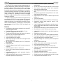
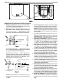
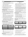
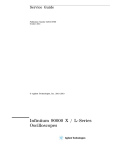
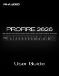
Figure 1
FRONT PANEL CONTROLS AND INDICATORS (Figure 1)
1. Pan Control: Adjusts the amount of input signal sent
to the Left and Right outputs. Each Pan knob has a
center detent position. To avoid accidental movement
of the knob once it has been set, it may be pushed in
flush with the front panel.
Note: Pan Control 3 becomes a Left/Right Balance
Control when the LINK switch is activated (see the
LINK switch description for details).
2. Input Level Bi-Color LED: Glows green to indicate
the presence and relative level of an input signal. Also
glows red if the input signal reaches 6 dB below the
clipping (distortion) level. To program this LED so that
it functions only as a clipping level indicator, open the
battery compartment and move DIP Switch 10 to the
Off position.
3. 1 kHz Tone Oscillator Switch: Use the 1 kHz tone to
send a reference signal to any device connected to an
FP33 output. The 1 kHz tone mutes all inputs. The tone
level can be adjusted with the Master control.
ies, the Battery Check indicates the status of the external operating voltage. When the mixer is using 9 V
batteries and an external dc supply, the Battery Check
indicates the status of the higher voltage source. A low
battery condition also is indicated when the Power On
LED changes to red and flashes at a slower rate. For
instructions on modifying the FP33 to allow only internal batteries or external power to be monitored at the
VU meter, see Internal Modifiable Functions.
Note: The audio signal is not interrupted when the
Battery Check switch is activated.
7. Output Peak/Limiter Bi-Color LED: Glows red for
the individual Left and Right Channels when the output signal reaches a factory preset peak level of +17
dBm. This peak level is user-adjustable from 0 dBm to
+17 dBm. (See the Peak LED Adjustment instructions.) If the Limiter is switched on, each LED glows
green to indicate Limiter operation. The LED will still
glow red if the preset peak level is reached before the
Limiter activation point is reached.
4. Link Switch: In the LINK position (up), this switch
links the gain controls of Inputs 2 and 3 so they act as
a stereo pair. Input 2 is Left and Input 3 is Right. The
Input 3 Gain knob adjusts the level of the stereo pair.
The Input 3 Pan knob adjusts the Left/Right balance.
8. Slate Button: Activates a 400 Hz Slate Tone for one
second and also activates the Slate Microphone. The
Slate Microphone remains on while the button is depressed. The Slate signal (Tone and Mic) appears at
the Left and Right outputs to identify the beginning of
a take. If desired, the Slate features can be modified
as follows: disable the Slate Tone; insert the Slate signal pre-Master control; or insert the Slate signal postMaster control. See the Internal DIP Switches table for
instructions.
Note: Channel 2 Gain and Pan are disabled when the
LINK switch is activated. The low-cut filters for Input 2
and Input 3 are not linked.
5. Slate Microphone: The built-in condenser microphone is activated when the Slate button is pressed.
See the Slate Button section for more information.
Note: To disable both the Slate microphone and the
Slate tone, set internal DIP Switches 5, 6, and 7 to Off.
Note: To disable both the Slate microphone and the
Slate tone, set internal DIP Switches 5, 6, and 7 to Off.
The Slate microphone may also be modified to act as
a talk-back microphone for communications. Refer to
the Internal Modifiable Functions section for details.
6. Meter Lamp/Battery Check Switch: The Meter
Lamp function is activated by momentarily pushing
this switch upward. This function can be internally preset for timed or toggled deactivation. See the table in
the Internal Switches and Controls section for details.
The Battery Check function is activated by momentarily pushing this switch downward. The status of the
two 9 V batteries is indicated on the VU meter. When
the mixer is using an external dc supply and no batter-
9. Power On/Off Switch: Turns the mixer on and off.
The mixer is on when this switch is in the “up” position.
10. Power On LED: Monitors the higher of the internal or
external voltage sources. Flashes green to indicate
power is on and voltage is greater than 12 Vdc.
Flashes red and slower to indicate low power (12 Vdc
or less).
When this LED monitors the internal battery level, it
glows red typically when 30 minutes of battery power
remain. Refer to the Internal Battery Life section. For
instructions on modifying the FP33 to allow only internal batteries or external power to be monitored at
2
ENGLISH
11.
12.
13.
14.
15.
ENGLISH
DIP Switches and Limiter Threshold Adjustment for
instructions.
16. Left/Right Channel Output Level Meters: 0 VU is
preset at a +4 dBm output level. This may be recalibrated for each meter by an internal trim potentiometer.
See the VU Meter Adjustment paragraph for instructions.
Note: Mechanical meters are used because LCD meters do not operate properly in cold weather; fluorescent meters drain batteries too quickly; and LED meters are difficult to see in sunlight.
17. Monitor Input Switch: In the center position, this
switch sends the post-master audio to the headphone
output. In the left (locking ) or right (momentary) position, it sends the audio signal from the Monitor In jack
to the headphone output.
18. Headphone Gain Control (Inner Knob): Adjusts the
headphone volume level.
the VU meter, refer to the Internal Modifiable Functions section.
Input Gain Control: Adjusts the gain level of each input channel. Rotating the knob counterclockwise reduces the gain and raises the input clipping point. Use
a low control setting to handle “hotter” input signals
without distortion. With the FP33 input circuit, microphones with a “hot” output may be used without an inline pad (attenuator). For best performance, adjust
each Input Gain control so the associated Input Level
LED illuminates red only on the loudest signal peaks.
Input Low-Cut Filter Switch: Provides low-frequency roll-off to reduce wind noise and rumble. When using the filter, the frequency response is down 6 dB at
150 Hz. The roll-off slope is 6 dB per octave.
Master Gain—Right Channel Output: The outer
ring controls the Right channel output gain. The dualclutched control lets the Right and Left outputs be adjusted individually. Set it to “0 dB” for unity gain.
Master Gain—Left Channel Output: The inner knob
controls the Left channel output gain. The dualclutched control lets the Right and Left outputs be adjusted individually. Set it to “0 dB” for unity gain.
Note: The 1 kHz tone oscillator level is set by the
Master Level controls. To calibrate other devices,
adjust the Master Level controls for a 0 VU response.
Output Peak Limiter Switch: Activates two fast-acting, peak-responding limiters, one for each output
channel. Limiters help prevent overload distortion
from unexpected loud input signals. The limiter activation is indicated by the Output Peak/Limiter LEDs,
which illuminate green.
The limiters may be changed to: operate independently; be linked as a stereo pair; activate at thresholds from 0 dBm to +15 dBm; and have release time
constants of 0.1 second or 1 second. See the Internal
WARNING: The headphone circuit is capable of
producing high volume levels that can damage the
user’s hearing. Make sure the headphone volume
setting is low (fully CCW) before putting on the
headphones.
19. Headphone Monitor Mode Switch (Outer Ring):
The user can monitor the FP33 output as: Stereo; Right
channel only; Mono (Left + Right); or Left channel only.
Note: This switch also affects the Monitor In signal.
When using a stereo MS microphone, such as the
Shure VP88, the user may wish to pass the mic signal
through the FP33 as separate Mid and Side signals,
yet hear decoded stereo in the headphones. Using the
Headphone MS Matrix, the user can monitor the FP33
output as: Discrete (Mid and Side); Side only, Stereo
(decoded MS), or Mono (Mid only). Refer to the Internal DIP Switch table for instructions on activating the
Headphone MS Matrix.
3
ENGLISH
ENGLISH
1
IN
1
MIC
1 LINE
MIC
2 LINE
MIC
3 LINE
2
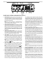
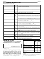
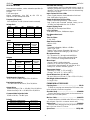
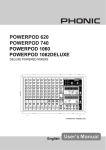
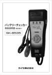
Figure 2
INPUT PANEL CONNECTORS AND CONTROLS (Figure 2)
1. Channel Inputs: The three female XLR inputs are
transformer balanced for superior rejection of hum,
RFI, and other interference. Each input can provide
48 V or 12 V phantom power (for condenser microphones); 12 V T (A-B) power (for condenser microphones); or no power (for dynamic microphones). See
the Internal Switches and Controls section.
2. Mic/Line Level Input Switch: Selects Microphone or
Line to match the incoming signal level. The Mic signal
level is typically 0.1–3 mV, and the Line signal level is
typically 0.1–3.0 V. In the Line level position, phantom
and T power are disconnected from the input.
2
1
MIX BUS
L
4
3
MON
TAPE
IN
OUT
5
6
OUT
R
MIC LINE MIC LINE
12-30 VDC IN
7
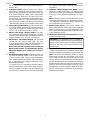
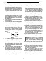
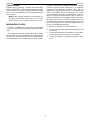
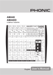
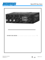
Figure 3
OUTPUT PANEL CONNECTORS AND CONTROLS (Figure 3)
1. Mix Bus Jack: Allows an FP33 to be connected to an
additional FP33 or FP32A mixer. A mix bus cable is
supplied with every FP33. The Mix Bus connection is
”two-way” and pre-Master. When two mixers are connected via the Mix Bus, all six inputs appear at both
mixers’ outputs. The Master Gain control of either mixer can be adjusted without affecting the output of the
other. This provides the equivalent of a six-input stereo
mixer with two separate Master output sections.
In signal to the headphones. Program audio is not
heard in the headphones when this switch is on.
Note: A “split-feed” (FP33 audio in one ear and Monitor
In audio in the other) can be accomplished via internal
DIP Switches 4 and 5. Also, an internal modification will
allow attenuated FP33 audio to be heard in the headphones even when the Monitor In switch is activated.
Refer to the Internal Modifiable Functions section.
5. Tape Output Jack: A stereo 3.5 mm mini-phone jack
(auxiliary level) to feed a cassette recorder, DAT machine, or semi-pro video recorder. This output can be
modified to provide a mono (L+R) signal; provide an unbalanced line level or mic level output; provide an isolated output containing only the Slate mic and Slate
tone. Refer to the Internal Modifiable Functions section.
Note: The output level of both mixers will drop by 6 dB
when they are connected via the Mix Bus. Increase
the Master Gain to compensate for this.
2. Main Output: The two male XLR outputs are transformer balanced and may be switched to Mic or Line
Level. The Line Level output can be modified to a true
600:. See the Internal Modifiable Functions section.
6. Mic/Line Level Output Switch: Selects Mic or Line
Level to match the input level of the device connected
to the FP33 output. The Mic signal level is typically
0.1–3 mV; the Line signal level is typically 0.1–3 V.
3. Headphones Outputs: A stereo 1/4 in. phone jack
and a stereo 3.5 mm mini-phone jack may be used
separately, simultaneously, or as auxiliary feeds to
other equipment.
7. 12–30 Vdc In Jack (External Power): This accepts
a non-polarized coaxial plug from a 12 to 30 Vdc external power supply. The external supply must have a
negative ground or a floating ground. A Shure PS20
or PS20E ac adapter, an automotive battery, or a rechargeable belt pack are all suitable power supplies.
4. Monitor In Jack: Designed to accept stereo line-level
signals. This 3.5 mm jack provides a “tape return” input or a communications channel input. This signal
appears only in the FP33 headphone circuit. Activating the front panel Monitor In switch routes the Monitor
4
(1*/,6+
(1*/,6+
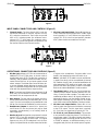
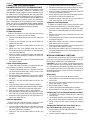
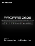
,17(51$/6:,7&+(6$1'&21752/6)LJXUH
)XVHDQG6SDUH)XVH'HVLJQHGWRSURWHFWWKH)3
IURPGDPDJHWKDWPD\UHVXOWIURPXVLQJDFRPPRQH[
WHUQDOGFSRZHUVXSSO\ZLWKRWKHUHOHFWURQLFGHYLFHV
&DXWLRQ'DPDJHPD\UHVXOWZKHQXVLQJDFRPPRQ
H[WHUQDOGFSRZHUVXSSO\ZLWKRWKHUHOHFWURQLFGHYLFHV
WKDWDUH´SRVLWLYHJURXQGµ6HSDUDWHSRZHUVXSSOLHVDUH
UHFRPPHQGHG
%DWWHU\&RPSDUWPHQW+ROGVWZR9DONDOLQHEDWWHU
LHV7ZRIUHVKEDWWHULHVZLOOSRZHUWKHXQLWIRUDERXW
HLJKWKRXUVXQGHUQRUPDOFRQGLWLRQV
0LFURSKRQH3RZHU6HOHFWLRQ6ZLWFK3RVLWLRQWKLV
VOLGHVZLWFKWRPDWFKWKHW\SHRILQSXWSRZHUGHVLUHG
4OP0OSITION64!"
5HIHUWR)LJXUH8VHG
ZLWKFHUWDLQ6HQQKHLVHUDQG6FKRHSVPLFURSKRQHV
)3
,QSXW
7
%DODQFHG$XGLR
WR0LFURSKRQH
3UHDPS
7
9
3RZHU
$%
²
0LFURSKRQH6XSSO\&XUUHQW
-IDDLE0OSITION$YNAMIC
1RGFSRZHURQSLQV
RU8VHGZLWKG\QDPLFPLFURSKRQHVRUFRQGHQVHU
PLFURSKRQHVWKDWKDYHLQWHUQDOEDWWHULHV
"OTTOM0OSITION0HANTOM
5HIHUWR)LJXUH,Q
WHUQDO',3VZLWFKVHOHFWVYROWVRUYROWV9
SKDQWRPSRZHUGUDLQVWKHEDWWHULHVIDVWHUWKDQ9
SKDQWRP SRZHU 8VHG ZLWK DOO FRQGHQVHU PLFUR
SKRQHVWKDWGRQRWUHTXLUH7SRZHU
)3,QSXW
/HYHO/3RWHQWLRPHWHU$WWHQXDWHVWKHOHYHORIWKH
)3OHIWFKDQQHOSURJUDPDXGLRWKDWLVIHGWRWKHKHDG
SKRQHPRQLWRUFLUFXLW7KLVGRHVQRWDIIHFWWKH0RQLWRU
,QOHYHOVDWWKHKHDGSKRQHRXWSXW
0HWHU$GM53RWHQWLRPHWHU$GMXVWVWKH5LJKWPHWHUWR
LQGLFDWH98DWDSUHVHWRXWSXWOHYHO7KHIDFWRU\VHWWLQJ
LVG%P7KHXVHUDGMXVWPHQWUDQJHLVWRG%P
5HIHUWRWKH980HWHU$GMXVWPHQWSDUDJUDSK
0HWHU$GM/3RWHQWLRPHWHU$GMXVWVWKH/HIWPHWHUWR
LQGLFDWH98DWDSUHVHWRXWSXWOHYHO7KHIDFWRU\VHW
WLQJLVG%P7KHXVHUDGMXVWPHQWUDQJHLVG%PWR
G%P6HHWKH980HWHU$GMXVWPHQWSDUDJUDSK
,QWHUQDO',36ZLWFKHVLQWHUQDO',3VZLWFKHVDO
ORZWKHXVHUWRFXVWRPL]HRSHUDWLRQ7KHIXQFWLRQRI
HDFK',3VZLWFKLVOLVWHGLQWKHWDEOHRQWKHIROORZLQJ
SDJH
0LFURSKRQH6XSSO\&XUUHQW
5
5
3KDQWRP
3KDQWRP
%DODQFHG$XGLR
WR0LFURSKRQH
3UHDPS
/HYHO53RWHQWLRPHWHU$WWHQXDWHVWKHOHYHORIWKH
)3 ULJKW FKDQQHO SURJUDP DXGLR WKDW LV IHG WR WKH
KHDGSKRQHPRQLWRU FLUFXLW 7KLV GRHV QRW DIIHFW WKH
0RQLWRU,QOHYHOVDWWKHKHDGSKRQHRXWSXW
3HDN/('53RWHQWLRPHWHU$GMXVWVWKH5LJKW3HDN
/('WROLJKWDWDSUHVHWRXWSXWOHYHO7KHIDFWRU\VHWWLQJ
LV G%P 7KH XVHU DGMXVWPHQW UDQJH LV G%P WR
G%P6HHWKH3HDN/('$GMXVWPHQWSDUDJUDSK
3HDN /(' / 3RWHQWLRPHWHU $GMXVWV WKH /HIW 3HDN
/('WROLJKWDWDSUHVHWRXWSXWOHYHO7KHIDFWRU\VHWWLQJ
LV G%P 7KH XVHU DGMXVWPHQW UDQJH LV G%P WR
G%P6HHWKH3HDN/('$GMXVWPHQWSDUDJUDSK
/LP$GM53RWHQWLRPHWHU$GMXVWVWKH5LJKWOLPLWHUWR
RSHUDWHDWDSUHVHWRXWSXWOHYHO7KHIDFWRU\VHWWLQJLV
G%P7KHXVHUDGMXVWPHQWUDQJHLVWRG%P
6HHWKH/LPLWHU7KUHVKROG$GMXVWPHQWSDUDJUDSK
/LP$GM/3RWHQWLRPHWHU$GMXVWVWKH/HIWOLPLWHUWRRS
HUDWH DW D SUHVHW RXWSXW OHYHO 7KH IDFWRU\ VHWWLQJ LV
G%P7KHXVHUDGMXVWPHQWUDQJHLVWRG%P
6HHWKH/LPLWHU7KUHVKROG$GMXVWPHQWSDUDJUDSK
²9
3KDQWRP
3RZHU
²
5 7 IRU 9
5 N7IRU9
&DXWLRQ%DODQFHGG\QDPLFPLFURSKRQHVZLOOQRWEH
GDPDJHGE\SKDQWRPSRZHUEXWPD\EHGDPDJHGE\
7SRZHU
ENGLISH
ENGLISH
INTERNAL SWITCHES AND CONTROLS (Cont.)
Note: Bold type indicates the Factory setting.
1
DIP SWITCH
LIM LINK
POSITION
ON
2
LIM RELEASE R
OFF
SHORT
LONG
3
LIM RELEASE L
4
MON DEFEAT R
SHORT
LONG
5
MON DEFEAT L
FUNCTION
Left and Right limiters act in tandem. If limiter thresholds are set differently, limiter action
is determined by the lower threshold setting.
Left and Right limiters act independently.
Right limiter release time constant is 0.1 second. Use for speech.
Right limiter release time constant is 1 second. Use for music.
Left limiter release time constant is 0.1 second. Use for speech.
Left limiter release time constant is 1 second. Use for music.
OFF
When front panel Monitor switch is activated, Monitor In signal is heard in Right headphone.
ON
OFF
When front panel Monitor switch is activated, Monitor In signal is not heard in Right headphone. Mixer audio remains in Right headphone.
When front panel Monitor switch is activated, Monitor In signal is heard in Left headphone.
ON
When front panel Monitor switch is activated, Monitor In signal is not heard in Left headphone. Mixer audio remains in Left headphone.
6
PRE-MAST SLATE
ON
Inserts slate tone and slate microphone into circuit before the Master gain control (pre–
master). Slate level is controlled by Master.
7
POST-MAST SLATE
OFF
Removes slate tone/slate microphone from pre-master cIrcuit.
ON
Inserts slate tone and slate microphone into FP33 circuit after the Master gain control
(post-master). Slate level not is controlled by Master.
OFF
Removes slate tone and slate microphone from FP33 post-master circuit.
8
SLATE TONE
ON
Slate tone (400 Hz) sounds for one second when front panel slate button is pushed. Slate
microphone also activates.
OFF
Slate tone does not sound when slate button is pushed. Slate microphone does activate.
9
METER LAMP
TOGGLED
Lamp turns on/off when front panel lamp switch is toggled. Automatic timed turnoff of lamp
will not occur.
Lamp turns on/off when front panel lamp switch is activated. If not manually switched off,
lamp will automatically turn off after 10 seconds to conserve battery life.
TIMED
10
PRESENCE LEDs
ON
OFF
Input LEDs illuminate green to indicate signal presence and relative level.
Input LEDs do not illuminate green. Input LEDs will still illuminate red to indicate 6 dB before clipping.
11
12 V OR 48 V PHANTOM
12V
Provides 12 Vdc phantom power if selected for channel input.
48V
Provides 48 Vdc phantom power if selected for channel input.
ON
Inserts MS decoding matrix into headphone circuit. User can monitor in stereo while allowing separate Mic and Side signals to pass through the FP33.
OFF
Removes MS decoding matrix from headphone circuit.
12
MS MATRIX FOR
HEADPHONES
POWERING THE FP33 MIXER
Mixer Operation
The FP33 can be powered by a 12–30 Vdc external power
supply while preserving the life of the internal batteries.
External Power Supplied
Internal Batteries
11.4 Vdc to 30 Vdc
OFF (200 PA current at 18 V)
<11.4 Vdc
ON (Full power for the FP33 is supplied by the higher voltage source)
BATTERY LIFE
The FP33 is designed for low current consumption.
Under typical conditions (+4 dBm into 600 : in continuous
use and no phantom–powered microphones, meter illumination, or headphones in use), and with two fresh 9 volt
alkaline batteries , the FP33 will operate for about eight
hours before the Power LED flashes. At this point, about 30
minutes of battery life remain. If more mixer features are
used, battery life will decrease accordingly (see table).
Battery
Current
(mA)
Battery
Life
(hours)*
(A) Idle, no signal
41
9
(B) As in (A) with +4 dBm continuous
output
46
7.8
(C) As in (B) with three Shure SM81 microphones at 12 V phantom power
50
7.5
(D) As in (B) with three Shure SM81 microphones at 48 V phantom power
57
6.0
(E) As in (B) with 63 : headphones
driven moderately loud (Sony MDRV6)
50
6.9
(F) As in (B) with meter illumination
continuously on
63
5.5
*Until Power LED begins to flash, and allowing 30 minutes to replace
batteries.
Note: Momentary use of headphones or meter illumination will not appreciably affect battery life.
6
(1*/,6+
(1*/,6+
0,;(56(783
23(5$7,21
3UHSDUHWKH)3VWHUHRPL[HUIRURSHUDWLRQDVIROORZV
)RULQWHUQDOEDWWHU\ RSHUDWLRQ OLIW WKH ODWFKRQ WKHWRS
SDQHODQGRSHQWKHEDWWHU\FRPSDUWPHQW,QVWDOOWZR9
DONDOLQHEDWWHULHVPDNLQJVXUHWKHSRODULW\²LVFRU
UHFW6HOHFWWKHSURSHUPLFURSKRQHSRZHULQJIRUHDFKLQ
SXWYLDWKHVOLGHVZLWFKHV&ORVHWKHFRPSDUWPHQWGRRU
DQGVHFXUHWKHODWFK)RUH[WHUQDOSRZHURSHUDWLRQSOXJ
DWR9GFVRXUFHLQWRWKH([WHUQDO3RZHUMDFNRQ
WKHULJKWVLGHSDQHORIWKH)3
&RQQHFWWKHPLFURSKRQHZLUHOHVVUHFHLYHURURWKHU
DXGLRVRXUFHWRWKHGHVLUHG,QSXW&KDQQHOFRQQHFWRU
RQWKHOHIWVLGHSDQHO
1RWH :KHQXVLQJDVWHUHRPLFURSKRQHVXFKDVWKH
6KXUH93FRQQHFWLWWR&KDQQHOVDQG8VHWKH
IURQWSDQHO/,1.VZLWFKWRPDNH,QSXWVDQGDVWHUHR
SDLU,QWKH/,1.PRGH&KDQQHO /HIWRU0LG&KDQ
QHO 5LJKWRU6LGH
3RVLWLRQHDFK0LF/LQH,QSXWVZLWFKEDVHGRQWKHOHYHO
RIWKHLQFRPLQJVRXUFH
&RQQHFWWKHFDPFRUGHU'$7PDFKLQHZLUHOHVVWUDQV
PLWWHURURWKHUHTXLSPHQWWRWKH/HIWDQG5LJKW2XWSXW
;/5FRQQHFWRUVRQWKHULJKWVLGHSDQHORIWKH)3
3RVLWLRQHDFK0LF/LQH2XWSXWVZLWFKEDVHGRQWKHLQ
SXWOHYHOUHTXLUHPHQWVRIWKHHTXLSPHQWFRQQHFWHGWR
WKH)3RXWSXWV
,ID´WDSHUHWXUQµRU0RQLWRU,QIHHGLQWRWKH)3LVUH
TXLUHGFRQQHFWDPPVWHUHRPDOHSOXJLQWRWKH
0RQ,QFRQQHFWRURQWKHULJKWVLGHSDQHO7KHVLJQDO
RQWKLVSOXJW\SLFDOO\FRPHVIURPWKHDXGLRRXWSXWRI
ZKDWHYHU GHYLFH LV EHLQJ IHG E\ WKH )3 6HH
)LJXUH
7RRSHUDWHWKH)3VWHUHRPL[HUSURFHHGDVIROORZV
$SSO\SRZHUWRWKHPL[HUE\VOLGLQJWKH2Q2IIVZLWFK
WRWKH2QSRVLWLRQ7KHJUHHQ3RZHU2Q/('ZLOOIODVK
DWDFRQVWDQWUDWHWRLQGLFDWHWKDWWKHPL[HULVWXUQHGRQ
&KHFNWKHPL[HUSRZHUVWDWXVE\PRYLQJWKHIURQWSDQHO
%DWWHU\&KHFNVZLWFKGRZQZDUGWRZDUGWKHEDWWHU\LFRQ
7KHQHHGOHRQWKHWRS98PHWHUZLOOVZLQJWRWKHVORSHG
UHG %$77 LQGLFDWLRQ ,I WKH QHHGOH IDOOV EHORZ WKH UHG
%$77LQGLFDWLRQWKHXQLWLVQRWUHFHLYLQJDGHTXDWHSRZHU
IURPWKHLQWHUQDO9EDWWHULHVRUWKHH[WHUQDOGFVXSSO\
0RYHWKHIURQWSDQHO021WRJJOHVZLWFKWRWKHFHQWHU
SRVLWLRQWRURXWH)3DXGLRWRWKHKHDGSKRQHV6HW
WLQJWKLVVZLWFKWRWKHOHIWRUULJKWURXWHVWKH0RQLWRU,Q
DXGLR WR WKH KHDGSKRQHV 7KH ULJKW SRVLWLRQ LV PR
PHQWDU\IRUTXLFNO\FKHFNLQJWKH0RQLWRU,QDXGLR
6OLGHWKH/,0VZLWFKWRWKHGHVLUHGSRVLWLRQ8SWRWXUQ
WKHRXWSXWOLPLWHUVRQ'RZQWRWXUQWKHPRII.HHSWKH
OLPLWHUVRQWRSURWHFWDJDLQVWRXWSXWRYHUORDG
3RVLWLRQWKH /RZ&XW)LOWHUVZLWFKHVIRUHDFK,QSXW8S
IRUORZFXWRII'RZQIRUORZFXWRQ
)RUDQLQLWLDOJDLQVHWWLQJURWDWHWKH0DVWHU*DLQNQRE
WR´G%µR·FORFN7KLVSURYLGHVXQLW\JDLQIRUWKH
RXWSXWVWDJHV1RWHWKH0DVWHU*DLQFDQEHDGMXVWHG
GXULQJPL[HURSHUDWLRQDVLQSXWOHYHOVYDU\
$FWLYDWHWKHN+]WRQHRVFLOODWRUE\VOLGLQJWKHVZLWFK
WRWKH2QXSSRVLWLRQ8VHWKHWRQHWRVHWWKHLQSXW
OHYHOFRQWURORIWKHGHYLFHIROORZLQJWKH)32QFH
WKHLQSXWOHYHORIWKHIROORZLQJGHYLFHLVVHWVOLGHWKH
VZLWFKWRWKH2IIGRZQSRVLWLRQWRWXUQRIIWKHWRQH
1RWH7KHWRQHRVFLOODWRURIWKH)3LVQRWXVHGWRVHW
WKHFRQWUROVRIWKH)37KRVHDUHVHWDFFRUGLQJWR
WKHLQSXWVLJQDOVFRPLQJLQWRWKH)3
5RWDWHWKH+HDGSKRQH0RQLWRU0RGHNQREWRWKH67
6WHUHRSRVLWLRQ
3XWRQKHDGSKRQHVDQGFDUHIXOO\DGMXVWWKHKHDGSKRQH
YROXPHFRQWURO
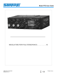
5,*+7$8',2
5,*+7$8',2
/()7$8',2
*5281'
*5281'
/()7$8',2
:$51,1*7KHKHDGSKRQHFLUFXLWLVFDSDEOHRI
SURGXFLQJORXGOHYHOVWKDWFDQGDPDJHWKHXVHU·V
KHDULQJ%HVXUHWKHKHDGSKRQHYROXPHVHWWLQJLV
ORZIXOO\&&:EHIRUHSXWWLQJRQWKHKHDGSKRQHV
,I DQ XQEDODQFHG RXWSXW IHHG LV GHVLUHG FRQQHFW D
PPVWHUHRPDOHSOXJLQWRWKH7DSH2XWFRQQHFWRU
RQWKHULJKWVLGHSDQHO7KLVZRXOGW\SLFDOO\IHHGDFDV
VHWWHUHFRUGHURUD'$7PDFKLQH5HIHUWR)LJXUH
3OXJ KHDGSKRQHV LQWR WKH VWHUHR LQ SKRQH RU
PPPLQL²SKRQHMDFNVRQWKHULJKWVLGHSDQHO
1RWH7KHWZRKHDGSKRQHRXWSXWFRQQHFWRUVPD\EH
XVHGVHSDUDWHO\VLPXOWDQHRXVO\RUDVDX[LOLDU\IHHGV
WRRWKHUHTXLSPHQW
7RLQWHUFRQQHFWWZRPL[HUVSOXJWKHVXSSOLHG0L[%XV
FDEOHLQWRWKH0L[%XVFRQQHFWRUVRIERWKPL[HUV
1RWH:KHQWZR)3RU)3$PL[HUVDUHLQWHUFRQ
QHFWHGYLDWKH0L[%XVWKH0DVWHU*DLQRQHLWKHUPL[HU
FDQEHDGMXVWHGZLWKRXWDIIHFWLQJWKHRWKHUPL[HU·VRXW
SXWOHYHO7KLV SURYLGHVWKHHTXLYDOHQWRIDVL[²LQSXW
VWHUHRPL[HUZLWKWZRVHSDUDWH0DVWHURXWSXWVHFWLRQV
6HWWKH0DVWHU*DLQ+HDGSKRQH9ROXPHDQGDOO,Q
SXW*DLQVIXOO\FRXQWHUFORFNZLVHRII
$GMXVWWKH,QSXW*DLQDQG3DQFRQWUROVEDVHGRQWKH
LQFRPLQJVLJQDOOHYHOV7KH,QSXW/('VVKRXOGIOLFNHU
UHGRQO\RQWKHORXGHVWLQSXWSHDNV$IWHUWKHVHVHW
WLQJVKDYHEHHQPDGHWKH3DQNQREVFDQEHSUHVVHG
IOXVKWRWKHIURQWSDQHOWRDYRLGDFFLGHQWDOPRYHPHQW
2EVHUYHWKHRXWSXWRQWKH98PHWHUVDQGDGMXVWWKH
0DVWHU*DLQWRREWDLQWKHGHVLUHGOHYHOV7U\WRNHHS
WKHDYHUDJHOHYHOVDURXQG´98µ
1RWH 7R LOOXPLQDWH WKH 98 PHWHUV PRYH WKH IURQW
SDQHOWRJJOHVZLWFKXSWRZDUGWKHOLJKWEXOEV\PERO
3UHVVWKH6ODWHEXWWRQWRLQVHUWDPRPHQWDU\+]
6ODWHWRQHLQWRWKH)3RXWSXWIRU´WDNHµLGHQWLILFDWLRQ
SXUSRVHV7KH)3PL[HULVQRZUHDG\IRUXVH
1RWH ,I GHVLUHG YRFDOO\ LGHQWLI\ WKH ´WDNHµ YLD WKH
6ODWH0LFZKLOHSUHVVLQJWKH6ODWHEXWWRQ
ENGLISH
ENGLISH
3. Slide the Limiter switch to the Off (down) position.
4. Adjust the Left Master gain control until the ac voltmeter reading is at the desired peak output level.
5. Open the battery compartment and turn the Peak LED
L trim pot completely clockwise.
6. Slowly adjust the trim pot counterclockwise until the
left Peak/Lim LED first illuminates red.
7. Repeat the above procedure for the right Peak/Lim
LED, using the Peak LED R trim pot.
CONNECTING FP33 TRANSFORMER
BALANCED OUTPUTS TO TELEPHONE LINES
In the Line position, the Left and Right XLR outputs can be
used to drive dc-biased, “dialed up” telephone lines,
although there may be a slight increase in distortion. Use of
the limiter circuit is strongly advised, with the FP33 limiter
threshold set to +4 dBm. Modification of the FP33 output impedance to 600: is recommended for proper fidelity. (See
the Internal Modifiable Functions section for instructions.)
When connecting the FP33 to a telephone line in the United
States, use of an FCC-Registered interface adapter between
the mixer and the telephone line is mandatory. Outside the
U.S., consult the local telecommunications authority.
Headphone Level Adjustments
To adjust the program level to match the audio signal
levels from a monitored source, proceed as follows:
1. Open the battery compartment and adjust the Headphone Level L and Headphone Level R ful counterclockwise.
2. Connect the device to be monitored via the 3.5 mm
Monitor In jack.
3. Move the Monitor Input Switch on the front panel to the
locking position (left).
4. Adjust the monitor input level, using the headphone
gain control on the front panel.
5. Move the Monitor Input switch on the front panel to the
post-master audio position (center).
6. Adjust the post-master audio to a comparable level,
using the Headphone Level L and Headphone Level
R potentiometers.
USER ADJUSTMENTS
VU Meter Adjustment
To set the VU Meters to a value other than the factory
setting (0 VU = +4 dBm), proceed as follows:
1. Connect a 600 : load across the Left XLR output set
for Line.
2. Connect an ac voltmeter (such as the HP 400GL) in
parallel with the load.
3. Slide the 1 kHz tone oscillator switch to the On (up)
position.
4. Adjust the 1 kHz Tone Oscillator level with the Left
(inside) Master gain control until the ac voltmeter reading is at the level desired.
5. Open the battery compartment door and adjust the
Left VU Level trim pot with a screwdriver until the Left
VU Meter reads 0.
6. Repeat the above procedure for the Right Output and
the Right VU Meter.
INTERNAL MODIFIABLE FUNCTIONS
Selected internal functions of the FP33 can be modified
by the user to fit special applications. Procedures for performing these modifications are listed below.
CAUTION: Due to the complex construction and extensive use of surface-mount components, modifications to
the FP33 must be performed by a qualified service technician. Contact the Shure Service Department or your authorized Shure Service Center for further information on
these modifications.
Limiter Threshold Adjustment
To adjust the Limiter threshold to a value other than the
factory setting (+15 dBm), proceed as follows:
1. Connect a 600 : load and an ac voltmeter across the
Left Line output as described in steps 1 and 2 of the
VU Meter Adjustment procedure.
2. Open the battery compartment and move DIP switch
1 to the Off position (refer to the chart on the inside of
the door).
3. Slide the 1 kHz tone oscillator switch to the On (up)
position.
4. Slide the Limiter switch to the Off (down) position.
5. Adjust the Left Master gain control until the ac voltmeter reading is 2 dB above the desired output level.
6. Slide the Limiter switch to the On (LIM) position.
7. Open the battery compartment and adjust the Lim Adj
L trim pot until the level drops to the desired reading.
8. Repeat the above procedure for the Right output, using the Lim Adj R trim pot.
Disassembly
1. Remove the six screws that secure the cover.
2. Slowly slide the cover backwards and unplug ribbon
cable P109.
3. Remove the three screws (marked with arrows) that
secure the upper PC board.
4. Remove the upper PC board.
5. Perform the appropriate modification procedure.
6. Reassemble the unit by doing Steps 1–4 in reverse.
Changing the Line Level Output Impedance to 600 :
1. Locate R674 and R668 on the bottom PC board and
remove them.
2. Locate X503 and X505 on the bottom PC board and solder a 470 : 1/2W resistor through the holes at X503.
3. Solder a 470 : 1/2W resistor through the holes at
X505.
Peak LED Adjustment
To adjust the Peak LED threshold to a value other than
the factory setting (+17 dBm), proceed as follows:
1. Connect a 600 : load and an ac voltmeter across the
Left Line output as described in steps 1 and 2 of the
VU Meter Adjustment procedure.
2. Slide the 1 kHz tone oscillator switch to the On (up)
position.
Changing the Tape Out Jack from Stereo (tip = L;
ring = R) to Mono (tip = L+R; ring = L+R)
1. Locate X504 on the top side of the lower PC board, by
the Tape Out jack.
2. Solder a jumper through the holes at X504.
8
ENGLISH
ENGLISH
C in PF= (85/frequency) - .33
Example for 200 Hz corner frequency
85/200 = .43
.43-.33 = .1 PF
Decreasing Tape Out Level to Mic Level
1. Locate R1112 and X511 (the top side of the bottom PC
board, by the L Out XLR connector).
2. Locate R1114 and X510 (the bottom side of the bottom
PC board, by the Tape Out jack).
3. Remove R1112 and R1114.
4. Solder a jumper through the holes at X511.
5. Solder a jumper through the holes at X510.
For a 200 Hz corner frequency, use a 0.1 PF capacitor.
2.
3.
Increasing the Tape Out Level by +10 dB
1. Locate R669 and R672 on the bottom PC board.
2. Remove these two resistors.
3. The Tape Out impedance is now 6 k:.
4.
Changing the Slate Mic and the Slate Tone to Feed
Only the Tape Out Jack
This modification provides an isolated, unbalanced output for talk-back. For example, the user could talk to a
boom operator though the Slate mic. The Monitor In function could be used to hear the boom operator’s response.
1. Locate and remove R663, R669, R670, R672, R673,
and R765 from the bottom PC board.
2. Solder a jumper through the holes at X504 (behind the
Tape Out jack).
3. Solder one end of an insulated jumper into the hole at
X600 (about 40 mm [1.5 in.] behind the Tape Out jack).
4. Solder the other end of this jumper to the jumper at X504.
5. Set the Pre-Mast Slate DIP switch (#6) to On.
6. Set the Post-Mast Slate DIP switch (#7) to Off.
7. The nominal Tape Out level is now –10 dBV (aux level).
The Modified Tape Out contains only the Slate tone and
Slate microphone. The Slate tone and Slate microphone are removed from the main outputs.
5.
Slowing Down Output Level Meters to Approximate
“True VU” Ballistics
1. Locate empty pads C302 and C303 on the top PC
board, behind the power switch.
2. Solder a 150PF x 6.3 V electrolytic capacitor in C302.
The + lead must face the meters.
3. Solder a 150PF x 6.3 V electrolytic capacitor in C303.
The + lead must face the meters.
4. To slow the meter response even more, further increase the PF value of C302 and C303.
Changing Battery Indicators to Monitor Internal or
External Power
The following modifications allow only the internal batteries or the external power supply to be monitored at the
VU meter.
Providing Mixer Audio in the Headphones when the
Monitor Switch is Activated
This modification allows the user to listen to the monitor
input signal and attenuated mixer audio simultaneously.
1. Locate X501 and X502 on the bottom PC board.
2. Determine the amount of attenuation desired for mixer
audio, using the following table.
Mixer Audio Attenuation
Less than 150 k:
10 dB
150 k:
15 dB
300 k:
Greater than 15 dB
Greater than 300 k:
Modification:
To monitor external To monitor internal
power only
battery power only
Procedure:
Remove R492
Remove R490
The following modifications allow the Red/Green Power
LED to indicate low voltage status for only the internal battery or the external power supply.
Required Resistor
Impedance
Less than 10 dB
Note: The capacitor must be a ceramic or film type,
non-polarized, with a 16 V or higher rating.
For Input 1, locate X811 and X812. Solder the new capacitor between these points.
For Input 2, locate X813 and X814. Solder the new capacitor between these points. Also locate X815 and X816
on the bottom board, just behind the input gain controls.
Solder another new capacitor between these points.
For Input 3, locate X809 and X810 on the bottom
board, just behind the input gain controls. Solder the
new capacitor between these points.
To raise the corner frequency higher than the factory
preset of 260 Hz, contact the Shure Technical Application Group at (847) 866-2525.
Modification:
To indicate low ex- To indicate low internal power only
ternal battery power only
Procedure:
Remove R493
Remove R491
Other Available Modifications
3. Solder a 1/8W or 1/4W resistor through the holes at
X501.
4. Solder a 1/8W or 1/4W resistor through the holes at
X502.
5. Activate the Monitor In switch. FP33 audio will be attenuated by the predetermined level.
Decreasing the Low-Cut Filter Corner Frequency
(3 dB down point)
1. Calculate a new capacitor value for the lower low-cut
corner frequency. Use the following formula:
x
Changing VU Meter Scale for Battery Voltage Indication
x
Converting FP32 to FP32A or FP33 Mix Bus
x
Increasing Output Level of Slate Mic
x
Power LED Red Flashing Point
x
Reduction of Headphone Circuit Output Impedance
x
Single Output Level Control
x
XLR Connector Change from Female to Male
For further information about these modifications, call
the Shure Technical Application Group at (847) 866–2525.
9
ENGLISH
ENGLISH
Overload and Shorting
Shorted outputs, even for prolonged periods, cause no
damage. Microphone inputs of up to 3 Vrms cause no
damage. The Line and monitor inputs can withstand signals of up to 30 Vrms.
Input Channel Bi-Color LEDs
Green: Signal presence; visual indication of mix level.
Red: 6 dB below clipping level.
Output Peak/Limiter Bi-Color LEDs
Green: Output being limited by 1 dB or more.
Red: Output peak threshold reached; factory set at
+17 dBm; user adjustable from 0 to 17 dBm.
Output Clipping Level
t+18 dBm at line output into 600:
Low–Cut Filters
6 dB down at 150 Hz; 6 dB/octave slope.
Pan Attenuation Level
45 dB.
Tone Oscillator
1 kHz r10%.
Slate Tone Oscillator
400 Hz r10%.
Limiter
Threshold: Adjustable; 0 dBm to +15 dBm.
Attack Time: 1 ms.
Release Time Constant: Selectable; 100 ms or 1 s.
Indicator: Green when limiting by 1 dB or more.
Microphone Power
12 V Phantom: 12 V through matched 680 :.
48 V Phantom : 48 V through matched 6.8 k:.
12 V T (A–B):12 V through matched 180:.
Mixer Power
Internal: Two 9 V alkaline batteries.
External: 12–30 Vdc to dc In jack; non–polarized.
Current Drain: Approximately 41 mA (idle) at 18 V.
Battery Life: 8 hours minimum, typical.
Temperature Range
Operating: 0q to 60q C (32q to 140qF).
Storage: –40q to 85q C (–40q to 185q F).
Overall Dimensions (H x W x D)
58 mm x 184 mm x 161 mm (7–1/4 x 6–3/8 x 2–1/4 in.).
Net Weight (without batteries)
1.6 kg (3.5 lbs).
SPECIFICATIONS
Measurement conditions, unless otherwise specified: Operating Voltage: 18 Vdc
Full gain
1 kHz input signal.
Output terminations: Line 600 : Mic 150 :
Tape Out 50 k:Headphone:
Frequency Response
20 to 20,000 Hz r2.0 dB (channel controls centered).
Voltage Gain
Input
Line
Mic
Headphone
Tape
Low-Z
Mic
(150 :)
78 dB
28 dB
89 dB
66 dB
Line
28 dB
–22 dB
39 dB
16 dB
Monitor
––
––
11 dB
––
Inputs
IMPEDANCE
Designed for
Actual
Use with
(Internal)
Input
Input Clip
Level
Mic
19 to 600 :
1 k:
–10 dBV
Line
d10 k:
50 k:
+36 dBV
Monitor
d 1 k:
10 k:
+21 dBV
Outputs
IMPEDANCE
Designed for
Actual
Use with
(Internal)
Input
Mic
Low-Z
inputs
Output Clip
Level
1:
–31 dBV
+18 dBm
Line
600 :
150 :
Tape
>10 k:
2.2 k:
+3 dBV
Headphones
8 to 200 :
300 :
+11 dBV
Total Harmonic Distortion
0.25% THD at +4 dBm output, 50 to 20,000 Hz.
Equivalent Input Noise
–127 dBV with 150 : source, 20 to 20,000 Hz.
FURNISHED ACCESSORIES
Carrying Case . . . . . . . . . . . . . . . . . . . . . . . . . . . . . 26A19
To wrap the carrying case around the FP33 mixer, refer
to the assembly instructions supplied.
Shoulder Strap . . . . . . . . . . . . . . . . . . . . . . . . . . 95A8508
Connect the strap’s swivel hooks to the metal ears located on the FP33 side panels.
Output Noise
Master level fully CCW: d –100 dBV, 20 to 20,000 Hz.
Master level fully CW: d –80 dBV, 20 to 20,000 Hz.
Common Mode Rejection Ratio
65 dB at 100 Hz, –20 dBV input.
Mix Bus Cable . . . . . . . . . . . . . . . . . . . . . . . . . . . 90A4313
A three-conductor, shielded cable 205 mm (8 in.) long
with a female 3-pin mini- connector at each end.
Rubber Feet . . . . . . . . . . . . . . . . . . . . . . . . . . . . 66A8010
If desired, these adhering feet may be placed on the bottom or the rear of the FP33 mixer.
Spare Fuse . . . . . . . . . . . . . . . . . . . . . . . . . . . 187AJ06A
Polarity
Mic/Line In to Mic/Line Out
Non-Inverting
Mic/Line In to Headphones
Non-Inverting
Mic/Line In to Tape Out
Non-Inverting
Mic/Line to Mix Bus
Inverting
Monitor In to Headphones
Non-Inverting
10
ENGLISH
ENGLISH
nications. These limits are designed to provide reasonable
protection against harmful interference in a residential
installation. This equipment generates, uses, and can
radiate radio frequency energy and, if not installed and
used in accordance with the instructions, may cause
harmful interference to radio communications. However,
there is no guarantee that interference will not occur in a
particular installation. If this equipment does cause harmful interference to radio or television reception (which can
be determined by turning the equipment off and on), the
user is encouraged to try to correct the interference by one
or more of the following measures:
1. Reorient or relocate the receiving antenna.
2. Increase the separation between the equipment and
the receiver.
3. Connect the equipment into an outlet on a circuit different from that to which the receiver is connected.
4. Consult your dealer or an experienced radio/TV technician.
CERTIFICATION
Eligible to bear CE Marking. Conforms to European EMC
Directive 89/336/EEC. Meets applicable tests and performance criteria in European Standard EN55103 (1996)
parts 1 and 2, for residential (E1) and light industrial (E2)
environments.
Note: Under extreme conditions of electrostatic discharge to the VU Meter Lamp Switch, the VU meter
may illuminate. This is normal and causes no harm.
INFORMATION TO USER
Changes or modifications not expressly approved by
Shure, Inc., could void your authority to operate this equipment.
This equipment has been tested and found to comply
with the limits for a Class B digital device pursuant to Part
15 of the FCC Rules and as set out in the Radio Interference Regulations of the Canadian Department of Commu-
11
SHURE Incorporated http://www.shure.com
United States, Canada, Latin America, Caribbean:
5800 W. Touhy Avenue, Niles, IL 60714-4608, U.S.A.
Phone: 847-600-2000 U.S. Fax: 847-600-1212 Int’l Fax: 847-600-6446
Europe, Middle East, Africa:
Shure Europe GmbH, Phone: 49-7131-72140 Fax: 49-7131-721414
Asia, Pacific:
Shure Asia Limited, Phone: 852-2893-4290 Fax: 852-2893-4055