1
IMPORTANT SAFETY INSTRUCTIONS
The apparatus shall not be exposed to dripping or splashing and that no objects ¿OOHG with liquids, such as vases,
shall be placed on the apparatus. The MAINS plug is used as the disconnect device, the disconnect device shall
remain readily operable.
Warning: the user shall not place this apparatus in the FRQ¿QHG area during the operation so that the mains switch
can be easily accessible.
1. Read these instructions before operating this
apparatus.
2. Keep these instructions for future reference.
CAUTION
RISK OF ELECTRIC SHOCK
DO NOT OPEN
3. Heed all warnings to ensure safe operation.
4. Follow all instructions provided in this document.
5. Do not use this apparatus near water or in locations
where condensation may occur.
6. Clean only with dry cloth. Do not use aerosol or liquid
cleaners. Unplug this apparatus before cleaning.
7. Do not block any of the ventilation openings. Install
in accordance with the manufacturer’s instructions.
CAUTION: TO REDUCE THE RISK OF ELECTRIC SHOCK,
DO NOT REMOVE COVER (OR BACK
NO USER SERVICEABLE PARTS INSIDE
REFER SERVICING TO QUALIFIED PERSONNEL
The lightning flash with arrowhead symbol, within an
equilateral triangle, is intended to alert the user to the
presence of uninsulated “dangerous voltage” within the
product’VHQFORVXUHWKDWPD\EHRIVXI¿FLHQW
8. Do not install near any heat sources such as radiators,
heat registers, stoves, or other apparatus (including
DPSOL¿HUVWKDWSURGXFHKHDW.
9. Do not defeat the safety purpose of the polarized or
grounding-type plug. A polarized plug has two blades
with one wider than the other. A grounding type plug
has two blades and a third grounding prong. The wide
blade or the third prong is provided for your safety. If
the provided plug does not ¿W into your outlet, consult
an electrician for replacement of the obsolete outlet.
10. Protect the power cord from being walked on or
pinched particularly at plug, convenience receptacles,
and the point where they exit from the apparatus.
magnitude to constitute a risk of electric shock to persons.
The exclamation point within an equilateral triangle is intended to alert the user to the presence of important operating and maintenance VHUYLFLQJ instructions in the literature
accompanying the appliance.
WARNING: To reduce the risk of ¿UH or electric shock, do
not expose this apparatus to rain or moisture.
CAUTION: Use of controls or adjustments or performance
of procedures other than those VSHFL¿HG may result in
hazardous radiation exposure.
11. Only use attachments/accessories VSHFL¿HG by the
manufacturer.
12. Use only with a cart, stand, tripod, bracket, or
table VSHFL¿HG by the manufacturer, or sold with
the apparatus. When a cart is used, use caution
when moving the cart/apparatus
combination to avoid injury from tipover.
13. Unplug this apparatus during lighting
storms or when unused for long
periods of time.
14. Refer all servicing to TXDOL¿HG service personnel.
Servicing is required when the apparatus has been
damaged in any way, such as power-supply cord or
plug is damaged, liquid has been spilled or objects
have fallen into the apparatus, the apparatus has
been exposed to rain or moisture, does not operate
normally, or has been dropped.
2
AM440/440D
AM440/440D
Compact Mixers
CONTENTS
INTRODUCTION ........................................................................................................................ 4
FEATURES................................................................................................................................. 4
GETTING STARTED .................................................................................................................. 5
CHANNEL SETUP ......................................................................................................................5
MAKING CONNECTIONS...........................................................................................................6
CONTROLS AND SETTINGS .....................................................................................................8
APPLICATION .......................................................................................................................... 12
DIMENSIONS........................................................................................................................... 13
DIGITAL EFFECT TABLE......................................................................................................... 14
SPECIFICATIONS.................................................................................................................... 15
BLOCK DIAGRAMS ................................................................................................................. 17
Phonic reserves the right to improve or alter any information suppied within this document without prior notice.
V1.1 APR 12, 2006
AM440/440D
3
,1752'8&7,21
)($785(6
7KDQN\RXIRUFKRRVLQJRQHRI3KRQLF¶VPDQ\TXDOLW\
FRPSDFWPL[HUV7KH$0DQG$0'&RPSDFW
0L[HUV±GHVLJQHG E\WKHLQJHQLRXV HQJLQHHUV WKDW
KDYH FUHDWHG D YDULHW\ RI PL[HUV IDQWDVWLF LQ VW\OH
DQGSHUIRUPDQFHLQWKHSDVW±GLVSOD\VVLPLODUSUR
¿FLHQF\WKDWSUHYLRXV3KRQLFSURGXFWVKDYHVKRZQ
ZLWKPRUHWKDQDIHZUH¿QHPHQWVRIFRXUVH7KH$0
VHULHVIHDWXUHVIXOOJDLQUDQJHVDPD]LQJO\ORZGLV
WRUWLRQ OHYHOV DQG LQFUHGLEO\ ZLGH G\QDPLF UDQJHV
MXVW VKRZLQJ WKH GRPLQDQFH WKHVH VPDOO PDFKLQHV
ZLOOKDYHLQWKHPL[LQJ:RUOG
&RPPRQ)HDWXUHV
:HNQRZKRZHDJHU\RXDUHWRJHWVWDUWHG±ZDQW
LQJ WR JHW WKH PL[HU RXW DQG KRRN LW DOO XS LV SURE
DEO\\RXUQXPEHURQHSULRULW\ULJKWQRZ±EXWEHIRUH
\RXGRZHVWURQJO\XUJH\RXWRWDNHDORRNWKURXJK
WKLVPDQXDO,QVLGH\RXZLOO¿QGLPSRUWDQWIDFWVDQG
¿JXUHV RQ WKH VHW XS XVH DQG DSSOLFDWLRQV RI \RXU
EUDQGQHZPL[HU,I\RXGRKDSSHQWREHRQHRIWKH
PDQ\SHRSOHZKRÀDWO\UHIXVHWRUHDGXVHUPDQXDOV
WKHQZHMXVWXUJH\RXWRDWOHDVWJODQFHDWWKH,QVWDQW
6HWXS VHFWLRQ$IWHU JODQFLQJ DW RU UHDGLQJ WKURXJK
WKHPDQXDOZHDSSODXG\RXLI\RXGRUHDGWKHHQWLUH
PDQXDO SOHDVH VWRUH LW LQ D SODFH WKDW LV HDV\ IRU
\RXWR¿QGEHFDXVHFKDQFHVDUHWKHUH¶VVRPHWKLQJ
\RXPLVVHGWKH¿UVWWLPHDURXQG
Ɣ
Ɣ
Ɣ
Ɣ
Ɣ
Ɣ
Ɣ
Ɣ
Ɣ
Ɣ
$XGLRSKLOH4XDOLW\XOWUDORZQRLVH
PRQRPLFOLQHFKDQQHOV
VWHUHRFKDQQHOV
$8;();VHQGVRQHDFKFKDQQHO
+]ORZFXW¿OWHURQPRQRFKDQQHO
EDQG(4RQHDFKFKDQQHO
9SKDQWRPSRZHURQPLFFKDQQHOV
&RQWURO URRP3KRQHV VRXUFH PDWUL[ IRU PD[L
PXPPRQLWRUÀH[LELOLW\
();$8; VHQG FXH IRU PRQLWRULQJ LQGLYLGXDO
FKDQQHO
%DODQFHGPDVWHURXWSXWZLWKPPIDGHUFRQWURO
$0'SOXV
Ɣ ELW '63 ZLWK (); WDSGHOD\ DQG
WHVWWRQHV
Ɣ 6HSDUDWH();URXWHFRQWURO
$0'
GETTING STARTED
CHANNEL SETUP
1.
1.
2.
3.
4.
5.
Ensure all power is turned off on your mixer. To
totally ensure this, the power supply should not
be connected to the unit.
All faders and level controls should be set at the
lowest level and all channels switched off to ensure no sound is inadvertently sent through the
outputs when the device is switched on. All levels can be altered to acceptable degrees after
the device is turned on using the channel setup
instructions.
Plug any necessary equipment into the device’s
YDULRXV RXWSXWV 7KLV FRXOG LQFOXGH DPSOL¿HUV
and speakers, monitors, signal processors, and/
or recording devices.
Plug the supplied power cable into the inlet on
the back of the device and then into a power
outlet of a suitable voltage.
Turn the power switch on and follow the channel setup instructions to get the most out of your
equipment.
AM440/440D
To ensure the correct audio level of the input
channel is selected, each of the level input controls of the Mixer should be turned counterclockwise or down as far as they will go.
2. No input other than the one being set should
have any device plugged in. This will ensure the
purest signal is used when setting channels.
3. Set the level control of the channel you are setting to the 0 dB mark.
4. Ensure the channel has a signal sent to it similar
to the signal that will be sent when in common
use. For example, if the channel is using a microphone, then you should speak or sing at the
same level the performer normally would during a
SHUIRUPDQFHLIDJXLWDULVSOXJJHGLQWRWKHFKDQnel, then the guitar should also be strummed as
it normally would be (and so on). This ensures
levels are completely accurate and avoids having to reset them later.
5. Set the gain so the Level Meter indicates the audio level is around 0 dB.
7KLVFKDQQHOLVQRZUHDG\WREHXVHG\RXFDQ
stop making the audio signal.
7. You can repeat the same process for other channels. Or not, it’s your call.
5
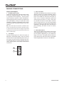
MAKING CONNECTIONS
Inputs and Outputs
1. XLR Microphone Jacks
These jacks accept typical 3-pin XLR inputs for balanced and unbalanced signals. They can be used
in conjunction with microphones – such as professional condenser, dynamic or ribbon microphones with standard XLR male connectors, and feature low
QRLVH SUHDPSOL¿HUV VHUYLQJ IRU FU\VWDO FOHDU VRXQG
replication. The AM440 and AM440D mixers feature
four standard XLR microphone inputs for your convenience.
NB. When these inputs are used with condenser microphones, the Phantom Power should be activated. Howev-
3. Stereo Channels
The AM440 and AM440D mixer feature a few stereo
FKDQQHOVWKURZQLQIRUPD[LPXPÀH[LELOLW\(DFKRI
these stereo channels features two 1/4” TRS phone
jacks, for the addition of various line level input devices, such as electronic keyboards, guitars and
external signal processors or mixers. These Stereo Channels can also be used as Mono channels,
where the signal from any 1/4” phone jack plugged
into the Left stereo input will cause the signal to be
duplicated to the Right input due to the miracle of
jack normalizing. This does not work in reverse,
however.
er, when Phantom Power button is engaged, single ended
(unbalanced) microphones and instruments should not be
used on the Mic inputs.
2. Line Inputs
This input accepts typical 1/4” TRS or TS inputs, for
balanced or unbalanced signals. There are various
numbers of these inputs depending which mixer you
are using. They can be used in conjunction with various line level devices, such as keyboards, drum machines, electric guitars, and a variety of other electric
instruments.
4. AUX / Effects Send
These 1/4” TS outputs may be used to connect to an
external digital effect processor, or even to an ampli¿HU DQG VSHDNHUV GHSHQGLQJ RQ \RXU GHVLUHG VHWtings), to the mixer. The signal sent from these outputs is fed from the AUX send control on the AM440
and the Digital Effect Processor on the AM440D.
1
2
6
AM440/440D
3KRQHV
7KLVVWHUHRRXWSXWSRUWLVVXLWHGIRUXVHZLWKKHDG
SKRQHV DOORZLQJ PRQLWRULQJ RI WKH PL[ 7KH DXGLR
OHYHORIWKLVRXWSXWLVFRQWUROOHGXVLQJWKH3KRQHV
6XEPL[FRQWURO
5HFRUG2XW
7KHVHRXWSXWVZLOODFFRPPRGDWH5&$FDEOHVDEOH
WREHIHGWRDYDULHW\RIUHFRUGLQJGHYLFHVVXFKDV
0' SOD\HUV DQG HYHQ ODSWRS FRPSXWHUV HQVXULQJ
WRWDOFRQWURORYHUUHFRUGLQJTXDOLW\
75HWXUQ
7KHVH 5&$ VWHUHR LQSXWV DUH XVHG WR FRQQHFW WKH
PL[HUZLWKH[WHUQDOGHYLFHVVXFKDVWDSHDQG&'
SOD\HUVRUHYHQ/DSWRSFRPSXWHUVUHFHLYLQJDVLJ
QDOIURPDQRWKHUVRXUFHDQGIHHGLQJLWWRWKH0DLQ
/5PL[LQJEXV
0DLQ/DQG52XWSXWV
7KHVHWZRSRUWVZLOORXWSXWWKH¿QDOVWHUHREDODQFHG
OLQHOHYHOVLJQDOVHQWIURPWKHPDLQPL[LQJEXV7KH
SULPDU\SXUSRVHRIWKHVHMDFNVLVWRVHQGWKHPDLQ
RXWSXWWRH[WHUQDOGHYLFHVZKLFKPD\LQFOXGHSRZHU
DPSOL¿HUV DQG LQWXUQ D SDLU RI VSHDNHUV RWKHU
PL[HUV DV ZHOO DV D ZLGH UDQJH RI RWKHU SRVVLEOH
VLJQDO SURFHVVRUV (TXDOL]HUV &URVVRYHUV HWFHW
HUD
&RQWURO5RRP2XWSXWV
7KHVHWZR´3KRQH-DFNRXWSXWVIHHGWKHVLJQDO
DOWHUHGE\WKH&RQWURO5RRP3KRQHVOHYHOFRQWURORQ
WKHIDFHRIWKHPL[HU7KLVRXWSXWKDVH[WHQVLYHXVH
DVLWFDQEHXVHGWRIHHGWKHVLJQDOIURPWKHPL[HUWR
DQDFWLYHPRQLWRUIRUWKHPRQLWRULQJRIWKHDXGLRVLJ
QDOIURPZLWKLQDERRWKDPRQJRWKHUSRVVLEOHXVHV
5HDU3DQHO
3RZHU&RQQHFWRU
7KLV SRUW LV IRU WKH DGGLWLRQ RI D SRZHU FDEOH DQG
VXSSO\DOORZLQJSRZHUWREHVXSSOLHGWRWKHPL[HU
3OHDVHXVHWKHSRZHUDGDSWRUWKDWLVLQFOXGHGZLWK
WKLVPL[HURQO\
$0'
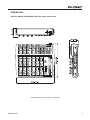
CONTROLS AND SETTINGS
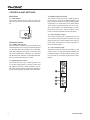
Rear Panel
11 Power Switch
This switch is used to turn the mixer on and off. Ensure you turn all level controls down before activating.
Channel Controls
12. Line/Mic Gain Control
This controls the sensitivity of the input signal of the
Line/Microphone input. The gain should be adjusted
to a level that allows the maximum use of the audio,
while still maintaining the quality of the feed. This
can be accomplished by adjusting it to a level that
will allow the peak indicator occasionally illuminate.
All 4 mono channels feature this control.
14. Middle Frequency Control
This control is used to provide a peaking style of
boost and cut to the level of middle frequency (2.5
kHz) sounds at a range of ±15 dB. Changing middle
IUHTXHQFLHVRIDQDXGLRIHHGFDQEHUDWKHUGLI¿FXOW
when used in a professional audio mix, as it is usually more desirable to cut middle frequency sounds
rather than boost them, thereby soothing overly
harsh vocal and instrument sounds in the audio.
15. Low Frequency Control
This control is used to give a shelving boost or cut
of ±15 dB to low frequency (80 Hz) sounds. This will
adjust the amount of bass included in the audio of
the channel, and bring more warmth and punch to
drums and bass guitars.
16. Low Cut Filter (75 Hz)
This button, located on channels 1 through to 4, will
DFWLYDWHDORZFXWKLJKSDVV¿OWHUWKDWUHGXFHVDOO
frequencies below 75 Hz at 18 dB per Octave, helping to remove any unwanted ground noise or stage
rumble.
13. High Frequency Control
This control is used to give a shelving boost or cut
of ±15 dB to high frequency (12 kHz) sounds. This
will adjust the amount of treble included in the audio of the channel, adding strength and crispness to
sounds such as guitars, cymbals, and synthesizers.
8
AM440/440D
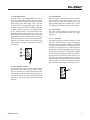
17. AUX / EFX Control
The AUX control on the AM440 allows the user to
send the corresponding signal to the AUX mixing
EXVWKH¿QDOOHYHORIZKLFKLVFRQWUROOHGE\WKH$8;
Send control on the main mixing panel. This signal is then sent to the AUX Send output, which can
EHXVHGLQFRQMXQFWLRQZLWKDQDPSOL¿HUDQGVWXGLR
or stage monitors, or simply as an auxiliary output
for any means required. The EFX control on the
AM440D alters the signal level that is sent to the
EFX mixing bus, which makes its way to the built-in
Digital Effects Processor and is in-turn sent through
the EFX send output. These controls are pre-fader,
therefore any changes made to the corresponding
channel level control are not applied to the AUX or
EFX signals.
17
18
20
19
18. Pan / Balance Controls
This alternates the degree or level of audio that the
left and right side of the main mix should receive.
On mono channels, this control will adjust the level
that the left and right should receive (pan), where as
on a stereo channel, adjusting the BAL control will
increase the left or right audio signals accordingly
(balance).
AM440/440D
19. Peak Indicator
This LED indicator will illuminate when the device
hits high peaks, 6 dB before overload occurs. It is
best to adjust the gain of the channel so that the
PEAK indicator lights up on intervals only, if at all.
This will ensure a greater dynamic range of audio.
20. Level Control
This rotary control will alter the signal level that is
sent from the corresponding channel to the main
mixing bus.
21. +4 / -10 Switch
This button, located on all stereo channels, is used
adjust the input sensitivity of the corresponding
channels, which will adapt the AM440 or AM440D
to external devices which may use different operating levels. If the input source is -10 dBV (consumer
audio level), it is best to engage the switch, allowing
the signal to be heard. The +4 dBu level is suitable
for Professional Audio signals, which are considerably higher than the consumer level. However, if you
are unsure of the source’s operating level, we suggest leaving the switch disengaged until you test the
source’s signal. You can then engage if necessary
(if the level of the input signal is obviously too low).
21
9
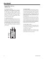
Digital Effect Section
(AM440D only)
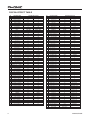
22. Digital Effect Display
This 2-digital numeric display shows the program
number that is currently applied to your EFX audio signal. When you rotate the Program control,
\RX FDQ VFUROO WKURXJK GLIIHUHQW SURJUDP QXPEHUV
however the display will revert back to the original
program if a new program is not selected within a
few seconds. For a list of available effects, please
observe the Digital Effect Table.
23. Sig and Clip Indicators
Located within the Digital Effect Display are Clip and
Sig LEDs. The Sig LED will light up when any signal is received by the effect processor, and the Clip
LED will light up shortly before excessive signals are
dynamically clipped. If the Clip LED lights up too often, it may be advisable to turn down one or all EFX
controls on input channels to ensure the signal level
is not too high.
22
23
24. Program Control
This control is used to scroll through the various effects. Turning the control clockwise will allow users
to ascend into higher program numbers, and turning
it counter-clockwise will allow users to descend into
lower program numbers. Pushing this control will
apply the new effect. When a tap-delay effect is selected, pressing this control will allow users to select
the tap-delay time.
By pushing the button several times, the effect processor interprets the time between last two pushes
and remembers this as the delay time, until the
button is pushed again (this is kept, even after the
power is turned off). When the tap delay effect is seOHFWHGDVPDOO/('ZLOOÀDVKZLWKLQWKHGLJLWDOHIIHFW
display window at the selected intervals.
25. EFX “to Main” Control
This will adjust the level of the Digital Effect signal
that will be sent to the Main left and right mixing bus
to be applied to your main feed.
26. EFX “to Ctrl” Button
This button is pushed to allow the signal from the
Digital Effect processor to be sent to the Control
Room outputs for monitoring purposes.
24
25
26
10
AM440/440D
Master Section
27. Phantom Power Switch
When this switch is in the on position, it activates
+48V of phantom power for all microphone inputs,
allowing condenser microphones (well, the ones that
don’t use batteries) to be used on these channels.
Activating Phantom Power will be accompanied by
an illuminated LED above the left channel Level Meter. Before turning Phantom Power on, turn all level
controls to a minimum to avoid the possibility of a
ghastly popping sound from the speakers.
NB. Phantom Power should be used in conjunction with
31. Ctrl Rm / Phones Control
This control is used to adjust the audio level of the
Control Room feed, which is sent to both the Control
5RRPRXWSXWVIRUPRQLWRULQJDFWLQJDVVLGH¿OORU
other purposes) and Phones outputs (to be used in
conjunction with headphones for monitoring).
32. Main L-R Control
7KLV PP IDGHU LV ¿QDO OHYHO FRQWURO IRU WKH PDLQ
left and right audio feed, sent to the Main L and R
outputs.
balanced microphones. When Phantom Power is engaged,
single ended (unbalanced) microphones and instruments
should not be used on the Mic inputs. Phantom Power will
not cause damage to most dynamic microphones, however
if unsure, the microphone’s user manual should be consulted.
28. AUX Send Control (AM440 only)
7KLVFRQWURODGMXVWVWKH¿QDOOHYHORIWKH$8;PL[LQJ
bus (as taken from the AUX controls on each channel strip), the audio of which is sent to the AUX Send
output (and sent to the Control Room/Phones output
when the AUX to Ctrl button is engaged).
29. 2T Return Routing Buttons
These two buttons allow users to decide the destination of the signal received by the RCA 2T Return
inputs. The “to Main” button sends the signal to the
main mix, whereas the “to Ctrl Rm” sends the signal
to the Control Room mixing bus for monitoring.
30. AUX “to Ctrl” Button (AM440 only)
When this button is activated, the AUX send signal
(the level of which is decided by the AUX send control) will be sent to the Control Room mixing bus for
monitoring purposes.
33. Level Meter
The AM’s stereo 4-segment level meter gives an accurate indication of when audio levels of the MAIN
L/R output reach certain levels. It is suggested for
the maximum use of audio to set the various levels
controls to a level slightly below that which would
cause the Peak LED to light up. This will help you
get the most out of your audio without causing any
distortion.
34. +48 Indicator
The +48 Indicator illuminates whenever the Phantom Power is activated.
35. Power Indicator
The Power Indicator will light up when the power of
the mixer is on.
27
34
35
28
33
29
32
30
31
AM440/440D
11
APPLICATION
There are potentially hundreds of ways to connect instruments and devices to the AM Mixers. It is advisable that you
H[SORUHWKHIXQFWLRQVDQG¿QGWKHEHVWVHWXSSRVVLEOHIRU\RXUQHHGVZKLFKPD\GHSHQGRQZKDWLQVWUXPHQWV\RX
wish to connect, as well as how many external devices you wish to connect and your required monitoring applications.
Combining the use of different instruments with the mixer’s special functions (such as digital effect processing, in the
case of the AM440D) will ensure that your audio sounds exactly the way you want it.
12
AM440/440D
DIMENSIONS
Both the AM440 and AM440D share the same dimensions.
* All measurements are shown in mm/inches.
AM440/440D
13
DIGITAL EFFECT TABLE
NO
PARAMETER SETTING
NO
PROGRAM NAME
PARAMETER SETTING
PAN
SPEED
56
SLOW PAN
0.1
R-->L
0
57
SLOW PAN 1
0.1
R<-->L
0.45
100
58
SLOW PAN 2
0.4
R-->L
0.6
90
59
MID SHIFT
0.8
R<-->L
MID ROOM 1
0.9
100
60
MID SHIFT 1
1.2
L-->R
MID ROOM 2
1
50
61
MID SHIFT 2
1.8
L-->R
06
BIG ROOM 1
1.2
100
62
MID SHIFT 3
1.8
R-->L
07
TUNNEL
3.85
100
63
FAST MOVE
3.4
R<-->L
HALL
REV-TIME
EARLY LEVEL
TREMOLO
SPEED
MODE-TYPE
08
JAZZ CLUB
0.9
90
64
LAZY TREMOLO
0.8
TRG
ROOM
REV-TIME
EARLY LEVEL
00
COMPACT ROOM 1
0.05
100
01
COMPACT ROOM 2
0.4
02
SMALL ROOM 1
03
SMALL ROOM 2
04
05
TYPE
09
SMALL HALL 1
1.5
72
65
VINTAGE TREMOLO
1.5
TRG
10
SMALL HALL 2
1.75
85
66
WARM TREMOLO
2.8
TRG
11
SPRING HALL
1.9
98
67
WARM TREMOLO 1
12
MID HALL 1
2.3
100
68
13
MID HALL 2
2.45
80
14
RECITAL HALL
2.7
96
15
BIG HALL 2
3.3
88
PLATE
REV-TIME
HPF
4.6
TRG
HOT TREMOLO
6.8
TRG
69
HOT TREMOLO 1
9.6
TRG
70
CRAZY TREMOLO 1
15
TRG
71
CRAZY TREMOLO 2
20
DELAY+REV
REV
TRG
DELAY-1
16
SMALL PLATE
0.9
0
72
DELAY+REV 1
1
1
17
TAIL PLATE
1.2
20
73
DELAY+REV 2
2
2
18
MID PLATE 1
1.3
0
74
DELAY+REV 3
3
3
19
MID PLATE 2
2.2
0
75
DELAY+REV 4
4
4
20
REVERSE PLATE
2.25
42
76
DELAY+REV 5
5
5
21
LONG PLATE 1
2.6
80
77
DELAY+REV 6
6
6
22
LONG PLATE 2
3
625
78
DELAY+REV 7
7
7
23
LONG PLATE 3
4.2
0
79
DELAY+REV 8
8
8
DELAY-1(stereo)
DELAY AVERG.
R-LEVEL
CHORUS+REV
REV
CHORUS
24
SHORT DELAY 1
0.07
60
80
CHORUS+REV 1
1
1
25
SHORT DELAY 2
0.14
60
81
CHORUS+REV 2
2
2
26
PING PONG DELAY
0.11
55
82
CHORUS+REV 3
3
3
27
MID DELAY 1
0.15
55
83
CHORUS+REV 4
4
4
0.3
60
84
CHORUS+REV 5
5
5
29
SHORT DELAY 1 (MONO)
0.06
100
85
CHORUS+REV 6
6
6
30
MID DELAY 1 (MONO)
0.13
100
86
CHORUS+REV 7
7
7
31
LONG DELAY 1 (MONO)
0.18
100
87
CHORUS+REV 8
8
8
CHORUS
LFO
DEPTH
FLANGER+REV
REV
FLANGER
32
SOFT CHORUS
0.2
56
88
FLANGER+REV 1
1
1
33
SOFT CHORUS 2
0.5
70
89
FLANGER+REV 2
2
2
34
SOFT CHORUS 3
0.8
75
90
FLANGER+REV 3
3
3
35
WARM CHORUS
1.8
85
91
FLANGER+REV 4
4
4
36
WARMER CHORUS 1
3.2
80
92
FLANGER+REV 5
5
5
37
WARMER CHORUS 2
5.2
45
93
FLANGER+REV 6
6
6
38
WARMER CHORUS 3
7.8
52
94
FLANGER+REV 7
7
7
39
HEAVY CHORUS
9.6
48
95
FLANGER+REV 8
8
8
FLANGER
LFO
DEPTH
GATED-REV
RELEASE
REV
40
CLASSIC FLANGER 1
0.1
44
96
GATED-REV-1 9
0.02
TAIL PLATE
41
CLASSIC FLANGER 2
0.3
63
97
GATED-REV-2 10
0.2
TAIL PLATE
42
GENTLE FLANGER
0.6
45
98
GATED-REV-1 9
0.02
REVERSE PLATE
43
WARM FLANGER
1.6
60
99
GATED-REV-2 10
0.5
REVERSE PLATE
44
MODERN FALANGER 1
2
85
TAP DELAY
FB LEVEL
RANGE
45
MODERN FALANGER 2
2.8
80
A0
TAP DELAY
0
100mS - 2.7S
46
DEEP FALANGER 1
4.6
75
A1
TAP DELAY
10
100mS - 2.7S
47
DEEP FALANGER 2
10
60
A2
TAP DELAY
20
100mS - 2.7S
PHASER
LFO
DELAY
A3
TAP DELAY
30
100mS - 2.7S
0.1
3.6
A4
TAP DELAY
40
100mS - 2.7S
28
14
PROGRAM NAME
MID DELAY 1
48
CLASSIC PHASER 1
49
CLASSIC PHASER 2
0.4
2.6
A5
TAP DELAY
50
100mS - 2.7S
50
COOL PHASER
1.4
0.7
A6
TAP DELAY
60
100mS - 2.7S
51
WARM PHASER
3.2
0.3
A7
TAP DELAY
70
100mS - 2.7S
52
HEAVY PHASER 1
5
1.2
A8
TAP DELAY
80
100mS - 2.7S
53
HEAVY PHASER 2
6
2.8
54
WILD PHASER 1
7.4
0.8
T0
55
WILD PHASER 2
9.6
4.8
T1
T2
PN
PINK NOISE
20Hz~20kHz
TEST TONE
LOW FREQUENCY
FREQUENCY
SHAPE
100Hz
SINEWAVE
MID FREQUENCY
1kHz
SINEWAVE
HIGH FREQUENCY
10kHz
SINEWAVE
AM440/440D
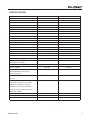
63(&,),&$7,216
0RGHO1DPH
$0
$0'
,QSXWV
7RWDO&KDQQHOV
%DODQFHG0RQR0LF/LQH&KDQQHO
%DODQFHG6WHUHR/LQH&KDQQHO
7,QSXW
6WHUHR5&$
6WHUHR5&$
2XWSXWV
0DLQ/56WHUHR
5HF2XW
&75/50/5
[´756%DO
[´756%DO
6WHUHR5&$
6WHUHR5&$
[´76
[´76
3KRQHV
&KDQQHO6WULSV
(I[6HQG
3DQ%DODQFH&RQWURO
<HV
9ROXPH&RQWUROV
5RWDU\
<HV
5RWDU\
0DVWHU6HFWLRQ
3KRQHV/HYHO&RQWURO
<HV
0DLQ/5/HYHO&RQWURO
0DLQ/5PPIDGHU
/HYHO0HWHU
3KDQWRP3RZHU6XSSO\
[VHJPHQW
<HV
0DLQ/5PPIDGHU
[VHJPHQW
9'&
9'&
+]a.+]
G%
G%
+]a.+]
G%
G%
G%
G%
)UHTXHQF\5HVSRQVH
0LFLQSXWWRDQ\RXWSXW
&URVVWDON.+]#G%X+]WR
.+]EDQGZLGWKFKDQQHOLQWR
PDLQ/5RXWSXWV
&KDQQHOIDGHUGRZQRWKHUFKDQQHOV
DWXQLW\
1RLVH+]a.+]PHDVXUHGDW
PDLQRXWSXW&KDQQHOVXQLWJDLQ
(4ÀDWDOOFKDQQHOVRQPDLQPL[
FKDQQHOV DVIDUOHIWDVSRVVLEOH
FKDQQHOV DVIDUULJKWDVSRVVLEOH
5HIHUHQFH G%X
0DVWHU#XQLW\FKDQQHOIDGHUGRZQ
G%X
G%X
0DVWHU#XQLW\FKDQQHOIDGHU#XQLW\
G%X
G%X
61UDWLRUHIWR
!G%
!G%
$0'
Model Name
AM 440
AM 440D
<-129.5 dBm
<-129.5 dBm
<0.005%
<0.005%
80 dB
80 dB
Mic Preamp Input
+10 dBu
+10 dBu
All Other Input
+22 dBu
+22 dBu
Balanced Output
+28 dBu
+28 dBu
Mic Preamp Input
2 K ohms
2 K ohms
All Other Input (except insert)
10 K ohms
10 K ohms
RCA 2T Output
1.1 K ohms
1.1 K ohms
3-band, +/-15 dB
3-band, +/-15 dB
80 Hz
80 Hz
Mid EQ
2.5 KHz
2.5 KHz
Hi EQ
12 KHz
12 KHz
75Hz (-18dB/oct)
75Hz (-18dB/oct)
N/A
100 effects with tap
Microphone Preamp E.I.N. (150
ohms terminated, max gain)
THD (Any output, 1KHz @ +14dBu,
20Hz to 20KHz, channel inputs)
CMRR (1 KHz @ -60dBu, Gain at
maximum)
Maximum Level
Impedance
Equalization
Low EQ
Low Cut Filter
Effect Processor
delay control
Power Requirement (external power
supply, depends on region)
Weight
Dimensions (WxHxD)
16
100VAC, 120VAC,
100VAC, 120VAC,
220~240VAC, 50/60Hz
220~240VAC, 50/60Hz
1.7kg (3.75 lbs)
1.72 kg (3.78 lbs)
242 x 55 x 225mm
242 x 55 x 225mm
(9.5” x 2.16” x 8.86”)
(9.5” x 2.16” x 8.86”)
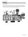
AM440/440D
$0%/2&.',$*5$0
0,&,1
/,1(,1
9
0212&+$11(/a
*OREDO 9
*$,1
/
5
+]+3)
/2:&87
67(5(2&+$11(/a
(4
+,*+ 0,'
/2 :
/(9 (/
/(9 (/
3($ .
/(9 (/
$8 ;
%$ /
$8 ;
3$1
0$,1/
0$,1/
0$,15
0$,15
$8;
$8;
0$,10,;
$8;0,;
0$,1)$'(5
$8;6(1'
7720$,1
772&75/50
$8;72&75/50
/0(7( 5
50(7(5
&75/503+21(6
0$,1/
0$,15
$8;6(1'
&75/50/
&75/505
3+21(6
5(&287/
5(&2875
7571/
75715
$0'
*$,1
+]+3)
/2:&87
67(5(2&+$11(/a
/
5
0212&+$11(/a
*OREDO 9
/2:
/(9 (/
/(9 (/
/(9 (/
352*5$0
',*,7$/);352&(6625
+,*+ 0,'
(4
3( $.
5
/
();
%$ /
();
();720$, 1
3$1
();
();
0$,15
0$,15
0$,1/
0$,1/
/,1(,1
0,&,1
9
();72&75/50
7720$,1
$8;0,;
0$,10,;
&75/503+21(6
50(7(5
/0(7( 5
772&75/50
$8;6(1'
0$,1)$'(5
$8;6(1'
3+21(6
&75/505
&75/50/
0$,15
0$,1/
75715
7571/
5(&2875
5(&287/
$0'%/2&.',$*5$0
$0'
72385&+$6($'',7,21$/3+21,&*($5$1'$&&(6625,(6
7RSXUFKDVH3KRQLFJHDUDQGRSWLRQDODFFHVVRULHVFRQWDFWDQ\DXWKRUL]HG3KRQLFGLVWULEXWRU)RU
DOLVWRI3KRQLFGLVWULEXWRUVSOHDVHYLVLWRXUZHEVLWHDWZZZSKRQLFFRPDQGFOLFNRQ*HW*HDU<RX
PD\DOVRFRQWDFW3KRQLFGLUHFWO\DQGZHZLOODVVLVW\RXLQORFDWLQJDGLVWULEXWRUQHDU\RX
6(59,&($1'5(3$,5
3KRQLFKDVRYHUVHUYLFHFHQWHUVZRUOGZLGH)RUUHSODFHPHQWSDUWVVHUYLFHDQGUHSDLUVSOHDVH
FRQWDFW WKH 3KRQLF GLVWULEXWRU LQ \RXU FRXQWU\ 3KRQLF GRHV QRW UHOHDVH VHUYLFH PDQXDOV WR
FRQVXPHUVDQGDGYLFHXVHUVWRQRWDWWHPSWDQ\VHOIUHSDLUVDVGRLQJVRYRLGVDOOZDUUDQWLHV<RX
FDQORFDWHDGHDOHUQHDU\RXDWZZZSKRQLFFRP
:$55$17<,1)250$7,21
3KRQLFVWDQGVEHKLQGHYHU\SURGXFWZHPDNHZLWKDQRKDVVOHVZDUUDQW\:DUUDQW\FRYHUDJH
PD\ EH H[WHQGHG GHSHQGLQJ RQ \RXU UHJLRQ 3KRQLF &RUSRUDWLRQ ZDUUDQWV WKLV SURGXFW IRU D
PLQLPXPRIRQH\HDUIURPWKHRULJLQDOGDWHRISXUFKDVHDJDLQVWGHIHFWVLQPDWHULDODQGZRUNPDQ
VKLSXQGHUXVHDVLQVWUXFWHGE\WKHXVHU¶VPDQXDO3KRQLFDWLWVRSWLRQVKDOOUHSDLURUUHSODFHWKH
GHIHFWLYHXQLWFRYHUHGE\WKLVZDUUDQW\3OHDVHUHWDLQWKHGDWHGVDOHVUHFHLSWDVHYLGHQFHRIWKH
GDWHRISXUFKDVH<RXZLOOQHHGLWIRUDQ\ZDUUDQW\VHUYLFH1RUHWXUQVRUUHSDLUVZLOOEHDFFHSWHG
ZLWKRXWDSURSHU50$QXPEHUUHWXUQPHUFKDQGLVHDXWKRUL]DWLRQ,QRUGHUWRNHHSWKLVZDUUDQW\
LQHIIHFWWKHSURGXFWPXVWKDYHEHHQKDQGOHGDQGXVHGDVSUHVFULEHGLQWKHLQVWUXFWLRQVDFFRP
SDQ\LQJWKLVZDUUDQW\$Q\WHPSHULQJRIWKHSURGXFWRUDWWHPSWVRIVHOIUHSDLUYRLGVDOOZDUUDQW\
7KLVZDUUDQW\GRHVQRWFRYHUDQ\GDPDJHGXHWRDFFLGHQWPLVXVHDEXVHRUQHJOLJHQFH7KLV
ZDUUDQW\ LV YDOLG RQO\ LI WKH SURGXFW ZDV SXUFKDVHG QHZ IURP DQ DXWKRUL]HG 3KRQLF
GHDOHUGLVWULEXWRU)RUFRPSOHWHZDUUDQW\SROLF\LQIRUPDWLRQSOHDVHYLVLWKWWSZZZSKRQLFFRP
&86720(56(59,&($1'7(&+1,&$/6833257
:H HQFRXUDJH \RX WR YLVLW RXU RQOLQH KHOS DW KWWSZZZSKRQLFFRPKHOS 7KHUH \RX FDQ ILQG
DQVZHUVWRIUHTXHQWO\DVNHGTXHVWLRQVWHFKWLSVGULYHUGRZQORDGVUHWXUQVLQVWUXFWLRQDQGRWKHUKHOSIXO
LQIRUPDWLRQ:HPDNHHYHU\HIIRUWWRDQVZHU\RXUTXHVWLRQVZLWKLQRQHEXVLQHVVGD\
3KRQLF$PHULFD&RUSRUDWLRQ
-RKQV5RDG
7DPSD)/
VXSSRUW#SKRQLFFRP
KWWSZZZSKRQLFFRP
20
AM440/440D