1
ENGLISH
ENGLISH
2
1
5
4
3
1 kHz
6
7
8
FP33
LINK
PEAK/LIM
L
R
L
PAN
R
L
PAN
BATT
R
PAN/BAL
7
3
7
3
7
-20
-2 -10-7-5 -3
0
R
10
1
11
0
10
2
0
10
0
VU
12
-20-10-7- -3
5
+15
MASTER dB
3
13
ON
+3 +5
L+R
0
+3 +5
R
ST
L
LIM
0
0
SLATE
10
L
VU
MIC
L
3
9
R
PEAK/LIM
MON
14 15
16
17
18
19
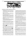
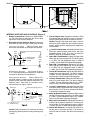
Figure 1
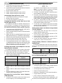
FRONT PANEL CONTROLS AND INDICATORS (Figure 1)
1. Pan Control: Adjusts the amount of input signal sent
to the Left and Right outputs. Each Pan knob has a
center detent position. To avoid accidental movement
of the knob once it has been set, it may be pushed in
flush with the front panel.
Note: Pan Control 3 becomes a Left/Right Balance
Control when the LINK switch is activated (see the
LINK switch description for details).
2. Input Level Bi-Color LED: Glows green to indicate
the presence and relative level of an input signal. Also
glows red if the input signal reaches 6 dB below the
clipping (distortion) level. To program this LED so that
it functions only as a clipping level indicator, open the
battery compartment and move DIP Switch 10 to the
Off position.
3. 1 kHz Tone Oscillator Switch: Use the 1 kHz tone to
send a reference signal to any device connected to an
FP33 output. The 1 kHz tone mutes all inputs. The tone
level can be adjusted with the Master control.
ies, the Battery Check indicates the status of the external operating voltage. When the mixer is using 9 V
batteries and an external dc supply, the Battery Check
indicates the status of the higher voltage source. A low
battery condition also is indicated when the Power On
LED changes to red and flashes at a slower rate. For
instructions on modifying the FP33 to allow only internal batteries or external power to be monitored at the
VU meter, see Internal Modifiable Functions.
Note: The audio signal is not interrupted when the
Battery Check switch is activated.
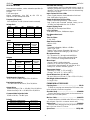
7. Output Peak/Limiter Bi-Color LED: Glows red for
the individual Left and Right Channels when the output signal reaches a factory preset peak level of +17
dBm. This peak level is user-adjustable from 0 dBm to
+17 dBm. (See the Peak LED Adjustment instructions.) If the Limiter is switched on, each LED glows
green to indicate Limiter operation. The LED will still
glow red if the preset peak level is reached before the
Limiter activation point is reached.
4. Link Switch: In the LINK position (up), this switch
links the gain controls of Inputs 2 and 3 so they act as
a stereo pair. Input 2 is Left and Input 3 is Right. The
Input 3 Gain knob adjusts the level of the stereo pair.
The Input 3 Pan knob adjusts the Left/Right balance.
8. Slate Button: Activates a 400 Hz Slate Tone for one
second and also activates the Slate Microphone. The
Slate Microphone remains on while the button is depressed. The Slate signal (Tone and Mic) appears at
the Left and Right outputs to identify the beginning of
a take. If desired, the Slate features can be modified
as follows: disable the Slate Tone; insert the Slate signal pre-Master control; or insert the Slate signal postMaster control. See the Internal DIP Switches table for
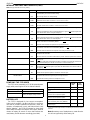
instructions.
Note: Channel 2 Gain and Pan are disabled when the
LINK switch is activated. The low-cut filters for Input 2
and Input 3 are not linked.
5. Slate Microphone: The built-in condenser microphone is activated when the Slate button is pressed.
See the Slate Button section for more information.
Note: To disable both the Slate microphone and the
Slate tone, set internal DIP Switches 5, 6, and 7 to Off.
Note: To disable both the Slate microphone and the
Slate tone, set internal DIP Switches 5, 6, and 7 to Off.
The Slate microphone may also be modified to act as
a talk-back microphone for communications. Refer to
the Internal Modifiable Functions section for details.
6. Meter Lamp/Battery Check Switch: The Meter
Lamp function is activated by momentarily pushing
this switch upward. This function can be internally preset for timed or toggled deactivation. See the table in
the Internal Switches and Controls section for details.
The Battery Check function is activated by momentarily pushing this switch downward. The status of the
two 9 V batteries is indicated on the VU meter. When
the mixer is using an external dc supply and no batter-
9. Power On/Off Switch: Turns the mixer on and off.
The mixer is on when this switch is in the “up” position.
10. Power On LED: Monitors the higher of the internal or
external voltage sources. Flashes green to indicate
power is on and voltage is greater than 12 Vdc.
Flashes red and slower to indicate low power (12 Vdc
or less).
When this LED monitors the internal battery level, it
glows red typically when 30 minutes of battery power
remain. Refer to the Internal Battery Life section. For
instructions on modifying the FP33 to allow only internal batteries or external power to be monitored at
2