1
Installation Procedures Continued
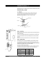
Install plumbing and wiring, and prepare pipe ends for connection as shown in
step 3.
Front View
COLD
INLET
VENT
OUTLET
Screw heater chassis to wall using screws or bolts suited to the wall surface.
Screws/bolts must be able to support the following weights when filled.
Step 3 – Connecting
a)
Plumbing
INLET
POSITION
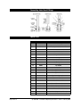
For exposed plumbing connection, connect the cold water inlet pipe from the
base of the heater directly to the 15 mm or 1/2 inch BSP compression fittings.
VENT
POSITION
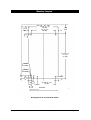
For concealed plumbing connections, connect the cold water pipe through the
rear of the chassis using a 15 mm or 1/2 inch BSP capillary elbow (# 63
Elbows).
Cold water pipes must be flushed before connection to the inlet. Any clogging
due to sediment or fines will adversely affect the operation of the heater.
Side View
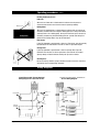
It is recommended that the heater be installed with a isolating valve which
allows it to be isolated from the mains supply for servicing.
45mm
Water pressure requirements:
Minimum - 0.1 bar, Maximum - 7 bar.
Elbow
Warning: If pressure is likely to exceed 7 bar, a pressure limiting valve must be
installed in the cold water supply line. We recommend a valve rated at
3.5 bar for this application.
250mm
Wiring
45 mm
b)
Venting
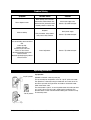
A vent at the base of the heater must be plumbed to a safe visible location as,
under certain conditions, it may discharge cold or boiling water and/or steam.
Concealed
Inlet
Concealed
Vent
For exposed vent plumbing, connect vent outlet from the base of heater to a
15 mm OD pipe which has a continuous fall, is no more than 3 metres long,
has no more than 3 right angle bends, and discharges to a waste water drain.
For concealed vent plumbing, connect plumbing to the vent outlet from the
heater rear using a capillary elbow protruding 45 mm from the wall.
Exposed vent
With Tundish
Zip Hydroboil - Installation & Operating Instructions - 81447 - February 2004
Page 5 of 12