1
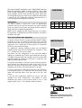
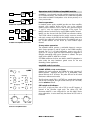
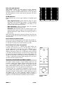
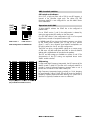
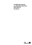
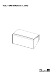
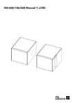
MAX12 Data Sheet Safety precautions Never stand in the immediate vicinity of loudspeakers driven at a high level. Professional loudspeaker systems are capable of causing a sound pressure level detrimental to human health. Seemingly non-critical sound levels (from approx. 95 dB SPL) can cause hearing damage if people are exposed to it over a long period. WARNING! In order to prevent accidents when deploying loudspeakers on the ground or when flown, please take note of the following: When setting up the loudspeakers or loudspeaker stands, make sure they are standing on a firm surface. If you place several systems on top of one another, use straps to secure them against movement. Only use accessories which have been tested and approved by d&b for assembly and mobile deployment. Pay attention to the correct application and maximum loading capacity of the accessories as specified in our "Rigging accessories" manual. Ensure that all additional hardware, fixings and fasteners used for installation or mobile deployment are of an appropriate size and load safety factor. Pay attention to the manufacturers instructions and to the relevant safety guidelines. Regularly check the loudspeaker housings and accessories for visible signs of wear and tear, and replace them when necessary. Regularly check all load bearing bolts in the mounting devices. Loudspeakers produce a static magnetic field even if they are not connected or are not in use. Therefore make sure when erecting and transporting loudspeakers that they are nowhere near equipment and objects which may be impaired or damaged by an external magnetic field. Generally speaking, a distance of 0.5 m (1.5 ft) from magnetic data carriers (floppy disks, audio and video tapes, bank cards, etc.) is sufficient; a distance of more than 1 m (3 ft) may be necessary with computer and video monitors. General Information MAX12 Data Sheet Version 3.0E, 02/2002, D2093.E.03 © by d&b audiotechnik AG 2002; all rights reserved. The information presented in this document is, to the best of our knowledge, correct. We will however not be held responsible for the consequences of any errors or omissions. Technical specifications, weights and dimensions should always be confirmed with d&b audiotechnik AG prior to inclusion in any additional documentation. d&b audiotechnik AG Eugen-Adolff-Strasse 134, D-71522 Backnang Telephone +49-7191-9669-0, Fax +49-7191-95 00 00 CAUTION! MAX12 MAX12 is a 2-way floor monitor system and uses a 12/2 coaxial driver combination with a passive crossover. The driver design allows the use of a compact, low height cabinet. MAX12 can be driven actively or passively. Coaxially mounting the 2 HF and 12 LF drivers creates a very compact single driver whilst retaining the benefits of separate magnetic assemblies. The drivers are positioned together to utilise the combined shape and geometry of the LF cone and HF horn to create a single waveguide with a controlled, symmetrical, 80° conical dispersion. The MAX12 cabinet is constructed from marine plywood and has an impact resistant paint finish. The front of the loudspeaker cabinet is fitted with a rigid metal grill covered with a replaceable acoustically transparent foam. A socket to accept a loudspeaker stand and four M10 threaded inserts complete the possible rigging options for MAX12. Fitted on the rear panel are two parallel wired Speakon-NL4 or EP5 connectors. The MAX12 cabinet does not require special controller electronics. As a stage monitor MAX12 is preferably operated with the P1200A mainframe equipped with the ampMAX module. The ampMAX module can be configured for passive and for 2-way active operation. The negligible signal delay with this type of construction closely approximates the ideal acoustic point source. The result is a loudspeaker with remarkable vocal presence and clarity, a neutral, balanced sound, high feedback stability and a high sound pressure level capability. The free field frequency response covers a 100 Hz to 18 kHz band - sufficient for speech reinforcement. When used as a stage monitor the floor coupling extends the frequency response down to 80 Hz. MAX12 as a stage monitor (baffle angle 35°) MAX12s angled side panels allow a choice of two set up angles when placed on stage (35° or 67°). Together with a comprehensive range of rigging hardware, the MAX12 cabinet allows fast and easy deployment of cabinets either as stage monitors or front-ofhouse in a main PA system. Viewed from the top, the angle between the MAX12 side panels is 45°. MAX12 cabinets can be deployed side by side to create semi-circular arrays, two cabinets result in an horizontal dispersion of 120° and three cabinets 170°. For applications which require deep bass, the LF response can be extended by using additional active subwoofer systems C7-SUB or C4-SUB. MAX12 can also be combined with the E15-BX passive bass extension speaker (not recommended when MAX12 is driven with an E-PAC). MAX12 with 03 Flying adapter MAX12 Data Sheet MAX12 Only operate MAX12 loudspeakers with a d&b P1200A mainframe fitted with ampMAX or AMP-L controller modules or with an d&b E-PAC in linear configuration. As an alternative other high quality power amplifiers may be used, provided their output power does not exceed 500 watts into 8 ohms and an additional subsonic filter is used (25 Hz with 12 dB/octave minimum), otherwise there is a risk of damaging the loudspeaker components. CAUTION! Connections The MAX12 cabinet is fitted with a pair of Speakon-NL4 connectors. All four pins of both connectors are wired in parallel. Using one connector as the input, the second connector allows for direct connection to additional loudspeakers. LF+ LF HF+ HF n.c. EP5 1 2 3 4 5 NL4 1+ 1 2+ 2 n.c. MAX12 can be supplied with EP5 output connectors as an option. Pin equivalents of Speakon-NL4 and EP5 connectors are listed in the table on the right. Four wire and two wire operation To allow the choice of active or passive operation MAX12 cabinets are driven by a four core cable. The HF and LF drivers are each fed by their own pair of pins and separate passive crossovers. Pins assignments 1+/1 connect the LF driver, pins 2+/2 connect the HF driver, as illustrated on the right. For applications requiring dedicated passive use, the MAX12 cabinets internal wiring can be configured for connection to pins 1+/1 allowing use of a two core cable. The passive two wire configuration is also used when MAX12 cabinets are combined with C-Series active subwoofers. Driven by a P1200A mainframe fitted with one AMP-L and one C-Series SUB controller module the cabinets can be fed by a single four core cable and linked together locally. To configure the cabinet for twin wire use the connector panel has to be removed by undoing the four Allen screws with a 2.5 mm Allen key. The wiring on the back of the connector panel can be changed to that shown in the lower illustration on the right. IMPORTANT! 1+ 1 2+ 2 1+ 1 2+ 2 Passive Crossover Passive Crossover Connector wiring (four wire operation) In the twin wire/passive configuration both the LF and HF drivers are connected to pins 1+/1. Note that only the HF driver wiring (white and white/red) differs from that used in the four wire version. In the twin wire configuration MAX12 can also be used with amplifiers from other manufacturers. The amplifier or signal distribution box needs to have positive signal on pin 1+ and negative signal on pin 1 of its speakon output connectors. MAX12 internal wiring of the connector panel to the crossover board in four wire and two wire operation MAX12 (3.0E) Operation with P1200A and ampMAX module INPUT A AMP A 1+ 1 2+ 2 OUT A INPUT B AMP B 1+ 1 2+ 2 OUT B P1200A with ampMAX, passive mode INPUT A Active Crossover Lo Hi INPUT B AMP A 1+ 1 2+ 2 OUT A AMP B 1+ 1 2+ 2 OUT B P1200A with ampMAX, active mode ampMAX is a two-channel controller module occupying both slots of a P1200A mainframe. The combination of P1200A and ampMAX allows MAX and MAX12 loudspeakers to be driven passively or in 2-way active mode. Passive operation In standard passive mode, ampMAX provides two linear amplifier channels, each amplifier driving all four pins on the channels Speakon output connector. Pins 1+ and 2+ carry positive and pins 1 and 2 carry the negative components of the signal. Two MAX12 cabinets can be driven by each P1200A amplifier channel. MAX12 can also be used with the E15-BX bass extension cabinet. The E15-BX cabinet is equipped with a passive crossover network and simply connects in parallel with the MAX12 cabinet without the need for any additional control electronics. One MAX12 and up to two E15-BX cabinets can be driven by each P1200A output channel. 2-way active operation The ampMAX module contains a switchable electronic crossover which routes seperate LF and HF signals to the P1200A amplifier channels. Pins 1+/1 of both loudspeaker outputs carry the LF signal, 2+/2 carry HF signal. The output connector pin assignment is changed automatically when active operation is selected. The input signal is fed to INPUT A, INPUT B is not used. A P1200A mainframe can drive two MAX or MAX12 loudspeakers in active mode, the extra headroom gained serves for the most demanding monitor applications. ampMAX module switches ampMAX 2 WAY ACTIVE CH A / LOW CH B / HIGH CUT CUT LFC LFC IS/GR IS/GR MUTE MUTE The left volume control (CH A / ACTIVE) now controls both channels and sets the overall level, the right volume control (CH B / HF-LEVEL) sets the relative HF level. 0 -6 -12 CUT switch and indicator Set to CUT, a high pass filter with a 130 Hz cut-off frequency is inserted in the controller signal path. The yellow CUT LED illuminates. MAX12 is now configured for use with d&b C-Series active subwoofers. In active mode only the channel A CUT switch is functional. 0 +6 CH A ACTIV E 2 WAY ACTIVE switch and indicator Selecting this switch configures the P1200A for active operation of MAX12 cabinets - channel A drives the 12" LF loudspeaker, whilst channel B drives the 2" HF driver. The yellow LED next to the switch illuminates to indicate active mode. -6 +6 -12 CH B HF-LEVEL Controls on ampMAX module MAX12 Data Sheet MAX12 LFC switch and indicator When MAX12 cabinets are used without an active subwoofer selecting LFC, Low Frequency Compensation, extends the low frequency response of MAX12 cabinets down to 75 Hz. The yellow LFC LED illuminates. In active mode only the channel A LFC switch is functional. IS/GR indicators These indicators give a three stage indication of ampMAX signal levels. − Input Signal Present (green) illuminates when the signal presented to the controller input exceeds a -36 dBu threshold value. The ISP circuit is unaffected by the setting of the controller mute switch and level control. − Gain Reduction (yellow) illuminates when the controller limiter reduces gain by more than 3 dB. − Overload (red) illuminates when an overload occurs in the signal path (input signal too high) or when the amplifier gain is reduced because the output current is too high (e.g. due to a short circuit). With active mode selected, the channel A indicators show the state of the LF channel and the channel B indicators show the state of the HF channel. 10 5 0 -5 -10 -15 -20 -25 -30 20 100 1k Frequency response of CUT and LFC circuits Level controls in passive mode The CH A and CH B detented level controls adjust the controller input sensitivity and have a 20 dB range, -14 dB to +6 dB, calibrated in 1 dB steps. The level controls are normally set to 0 dB. Level controls in 2-way active mode In active mode the CH A / ACTIVE level control adjusts the controller input sensitivity and has a 20 dB range, 14 db to +6 dB, calibrated in 1 dB steps. The CH B/ HF-LEVEL control adjusts relative HF level in 0.5 dB steps. For a flat response, whatever the setting of the CH A / ACTIVE level control, the CH B / HF-LEVEL control should be set to 0 dB. The more precise 0.5 dB HF level detent settings invalidate the control scale markings. To account for the actual 10 dB range of HF level adjustment from 7 dB to +3 dB divide the control scale setting by two to arrive at the actual value for relative HF level. Operation with P1200A and AMP-L module The AMP-L module occupies a single P1200A module slot and provides a single linear amplifier channel, which drives the pins 1+/1 of the respective output connector. For operation with the AMP-L module MAX12 cabinets have to be configured for two wire operation (see section "Four wire and two wire operation"). In passive mode up to two MAX12 loudspeakers can be driven by each P1200A power amplifier channel. Fitting one AMP-L and one subwoofer controller module allows a single mainframe to drive two MAX12 and two active subwoofer cabinets (C7-SUB or C4-SUB). All cabinets can be linked together locally and fed by a single four-core cable from either mainframe output connector. MAX12 (3.0E) 10k AMP-L CUT OVL ISP GR MUTE 0 -6 +6 -12 dB Controls on AMP-L module 20k AMP-L module switches CUT switch and indicator Set to CUT, a high pass filter with a 130 Hz cut-off frequency is inserted in the controller signal path. The yellow CUT LED illuminates. MAX12 is now configured for use with d&b C-Series active subwoofers. REMOTE LO IMP 1234 DELAY ON REMOTE LO IMP ON ON 1 2 3 4 5 6 Operation with E-PAC To drive MAX12 cabinets the E-PAC has to be configured to LINEAR mode. For an E-PAC version 1 and 2, the configuration is selected by setting the appropriate DIP switches on the rear panel. 1 2 3 4 5 6 7 8 SPKR HFA CUT E-PAC version 1 For an E-PAC version 3, the configuration is set via a front panel digital rotary encoder in conjunction with an LCD. In LINEAR mode all four pins on the Speakon connector are driven by the E-PAC power amplifier, pins 1+ and 2+ carry positive signal, 1 and 2 carry negative signal. MAX12 loudspeakers can be used in either four wire or two wire configuration. E-PAC version 2 E-PAC Configuration for LINEAR mode The E-PAC can drive a single MAX12 cabinet at an output power of 300 watts. LO IMP mode allows the E-PAC to drive two MAX12 cabinets with a 6 dB reduction of input level to the speakers. The CUT and HFA settings are available on versions 2 and 3. The characteristics of the CUT setting are explained above under "AMP-L module switches". HFA setting In HFA mode (High Frequency Attenuation), the HF response of the MAX12 system is rolled off. The HFA circuit configures MAX12 to provide a natural, balanced frequency response when a unit is placed close to listeners in near field or delay use. 10 5 0 -5 -10 High Frequency Attenuation begins gradually at 1 kHz, dropping by approximately 3 dB at 10 kHz. This roll-off mimics the decline in frequency response experienced when listening to a system from a distance in a typically reverberant room or auditorium. -15 -20 -25 -30 20 100 1k 10k 20k Frequency response correction of HFA circuit (only available with E-PAC version 2) MAX12 Data Sheet MAX12 Dispersion characteristics Due to the conical coverage pattern of the coaxial driver design, the horizontal and vertical dispersion characteristics of MAX12 are largely identical (slight differences which do occur are attributable to the asymmetric cabinet shape). The diagram below shows dispersion angle versus frequency plotted using lines of equal sound pressure (isobars) at -6 dB and -12 dB. MAX12 isobar diagram Frequency response The graph below shows the different response curves for MAX12 in free field driven with the P1200A mainframe with ampMAX. The response in standard mode is equivalent to the operation with a linear power amplifier. 110 10 105 5 100 0 95 -5 LFC 90 LFC -10 CUT 85 -15 80 -20 75 -25 70 20 100 1k 10k 20k MAX12 frequency response, (1m, free field) standard (linear, 2,83 V), LFC and CUT switch settings MAX12 -30 20 100 1k 10k 20k MAX12 frequency response, floor position, Microphone on axis, height 1.5 m, standard and LFC switch settings (3.0E) Technical specifications MAX12 system data, passive setup Max. sound pressure (1 m, free field) with P1200A........................................... 132 dB Max. sound pressure (1 m, free field) with E-PAC ............................................. 130 dB (SPLmax peak, pink noise test signal with crest factor of 4) Input level (SPLmax) ................................................................................................. +13 dBu Input level (100 dB-SPL / 1 m)............................................................................... 16 dBu Polarity to controller INPUT (XLR pin 2: + / 3: ) ...................................LF: + / HF: MAX12 system data, active setup with ampMAX Max. sound pressure (1 m, free field).................................................................... 134 dB (SPLmax peak, pink noise test signal with crest factor of 4) Input level (SPLmax) ................................................................................................. +15 dBu Input level (100 dB-SPL / 1 m)............................................................................... 16 dBu Polarity to controller INPUT (XLR pin 2: + / 3: ) .................................. LF: + / HF: + MAX12 loudspeaker 458 [18.03"] MAX12 wiring diagram 324 [12.76"] 486 [19.13"] 306 [12.04"] Frequency response (5 dB, free field) ...............................................100 Hz 18 kHz Frequency response (-5 dB, floor coupling) ......................................... 80 Hz 18 kHz Sensivity (2.83 V / 1 m) ................................................................................................99 dB Nominal impedance ................................................................................................... 8 ohms Power handling capacity (RMS / peak 10 ms)......................................250 / 1200 W Nominal dispersion angle ................................................................................. 80° conical Connections ...............................................................................................2 x Speakon-NL4 .................................................................................................................... (optional 2 x EP-5) Pin assignments Speakon-NL4.........................................................................HF 2+ / 2 ..................................................................................................................................LF 1+ / 1 Pin assignments EP5 ..................................................................................................HF 3 / 4 ........................................................................................................................................LF 1 / 2 Weight ................................................................................................................. 22 kg (48 lb) 425 [16.73"] MAX12 cabinet dimensions in mm [inch] MAX12 Data Sheet MAX12 d&b audiotechnik AG, Eugen-Adolff-Str. 134, D-71522 Backnang, Germany, Phone +49-7191-9669-0, Fax +49-7191-95 00 00