1
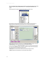
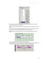
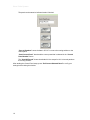
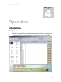
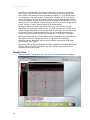
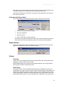
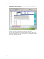
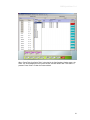
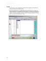
SIERRA VIDEO SYSTEMS
G.R.I.P. Router Software V3.1.0
Quick Start Guide
Quick Start
Guide
G.R.I.P. ROUTER SOFTWARE
Quick Start Guide
© Sierra Video Systems
P.O. Box 2462 Grass Valley, CA 95945
Tel: (530) 478-1000
Fax: (530) 478-1105
Email: [email protected]
Version 3.1.0
Publication Date: January 2005
The information contained in this manual is subject to change by Sierra Video System
© Sierra Video Systems
Table of
Contents
Introduction
Overview
1
1
Installation
3
Quick Start
7
Operating system requirements 3
GRIP Upgrades
3
PC Com Port Connection
5
Set up I/O and level names
Category Setup
Names
Set up control panels
Operation
Introduction
Main Screen
Graphic View
Alternate switching method
Status Router
Salvos
Overview
Salvo Setup
Locks
8
10
11
13
17
17
17
18
19
19
19
19
19
22
Contents I
Sierra Video Systems
1
Chapter
Introduction
Overview
G.R.I.P. (Graphical Router Interface Program) is a Graphics User Interface, (GUI), based
control system which can program and control most functions in Sierra Video Systems’
(SVS) serial controlled routing switchers. This includes switchers from the Manzanita
family (with serial control) through the large-scale Sequoia switchers.
G.R.I.P. allows users the ability to name sources and destinations, levels, router
configuration, router “mapping”, and set up personalities of individual control panels.
Likewise, G.R.I.P. provides graphical communication with the router processor
eliminating the need for antiquated terminal communication.
G.R.I.P. allows users to build and execute up to 40 “salvos” that can be accessed using
SVS programmable control panels, as well as access from the G.R.I.P. screen itself.
A router database is built in G.R.I.P. and copies can be stored and reinstalled in case of
catastrophic failure of the router or PC.
All routing switchers are simple devices in concept but once a system is developed,
control and configuration can be a tedious and confusing task. G.R.I.P. simplifies the
configuration and control of your switcher as well as retaining data stored in the switcher
in case of failure or processor software updates.
The G.R.I.P. functions are spread throughout the PC environment including the Window
registry and systems directory.
1
Sierra Video Systems
Installation
2
Chapter
Operating system requirements
P III or better
128 M Ram
1024x768 monitor and video card
Windows 98 or newer
100 M disk space
Set the PC video display to 1024 by 768 pixels, High color (16 bit), small fonts.
If large fonts are used, many GRIP labels will be clipped.
G.R.I.P. requires router software version 7.01 or newer to be installed. If an earlier
version is installed and running, please contact the factory for help in the installation or
you may experience the loss of user data such as Input/Output names. Older versions of
router software do not support all G.R.I.P. functions.
Insert CD ROM (or download exe from the Sierra Video.com web site) and Double-Click
on the “Setup.EXE” icon. Read and accept the software license. Please browse the
“Read Me” file for information on the installation.
For G.R.I.P. to work properly, an RS232 serial Comport is required to interface to the
routing switcher. Earlier versions of switchers may not have the standard RS232
connector to plug into the “PC” serial port using a standard cable. Please check the
router’s manual for the RS232 pin connections of your switcher.
If there is difficulty in Comport selection, please call technical support at SVS. Comport
parameters can be modified at any time within G.R.I.P. under “Routing switcher
Configuration”, “Communications Setup” or by running Regedit.exe and modifying the
“Comport” parameters.
GRIP Upgrades
It is recommended that you save a copy of your current database before installing a
newer version of GRIP over an earlier version. See the section on Database
Management of this manual, or contact the factory for assistance on locating the
database in GRIP versions 2.1.5 or earlier.
Pay close attention to installations over earlier versions of G.R.I.P. as changes may
require different tables in the database. If an “ODBC” error is displayed, the earlier
version of GRIP that was installed has a different database path than the newer version
you have installed. This can be corrected by editing the data path in the PC’s registry.
First, select “Run” from the start menu and type “regedit” in the window.
3
Sierra Video Systems
Select “OK”. The Registry Editor will open.
Click on the “+” next to HKEY_CURRENT_USER.
Click on the “+” next to Software.
Click on the “+” next to VB and VBA Program Settings.
Click on the “+” next to Eureka.
Click on the folder “Setup”.
In the window on the right, locate “DataPath” in the Name column. If the datapath shown
on the right (in the Data column) does not say C:\Program Files\SVS\GRIP, double click
on the ICON next to “DataPath” and the correct path in the Value data window.
4
GRIP Quick Start 3.1.0
PC Com Port Connection
SVS routing switchers are shipped from the factory with the baud rate set at 9600 Baud.
The Serial cable should be installed into the “Host” port on the back of the switcher and
Com Port 1 on the PC.
The router’s processor is shipped from the factory with the default settings. Please see
the router’s manual for more information regarding processor dipswitch settings.
SVS routing switchers use only 3 pins of a standard 9 pin D serial cable. In most cases
an “off the shelf” one-to-one cable may be used. Refer to the router’s user’s guide for
correct serial connection on the router host port.
PC Serial Cable Connections
Pin
RS-232
1
Not Used
2
Transmit
3
Receive
4
Not Used
5
Ground
6
Not Used
7
Not Used
8
Not Used
9
Not Used
Note:
Some versions of Windows do not allow GRIP to turn off the function of pin 8 on your PC. It may
be necessary to remove pin 8 from the serial cable in order for GRIP to perform adequately.
If pin 8 is an issue, the following message will display;
Cabling problem with Pin 8 RS232, please check cabling, exiting Grip & switching to
AutoBaud Check.
5
Sierra Video Systems
3
Chapter
Quick Start
This Section covers the most often used router configurations. Details of GRIP router
configurations can be found in the GRIP User’s Guide.
Match the GRIP database to the router’s configuration.
GRIP contains a default database. The GRIP database must read and store the size of
your router before you can proceed with configuration.
Double click on the GRIP icon. The program will start.
Select “Yes” to all messages. The Graphic View screen will open.
7
Sierra Video Systems
Select the “Main Screen” tab.
Set up I/O and level names
Select “Names Setup” from the Router Configuration drop down menu.
8
GRIP Quick Start 3.1.0
9
Sierra Video Systems
Category Setup
The first step in the names process is to setup categories.
Categories are the user defined prefix and suffix.
Select “Category Setup” from the Names Setup screen menu:
The Following screen will be displayed:
This window creates and manages the Categories that are used in the Names window
and the Control Panel setup screen.
Two pages of 10 categories are available to be entered. Page 1 is for the Prefix; page 2
is for the Suffix. Select the button number to be entered in the text input grid and type the
name into the field. This utility is useful when naming Sources and Destinations in the
router. See “Names Setup.”
Entering new text in the excel-like display modifies categories. All changes are immediate
and are set in the Database upon any mouse or tab action.
10
GRIP Quick Start 3.1.0
Names
After entering your prefix and suffix, you are ready to name the inputs and outputs. Exit
the Category Setup screen.
“Field Entry Options” determines how many fields in the spreadsheet get changed after
an entry. Normally all “Levels” of a source or destination have the same name with a
suffix added to the name, such as, VTR1 – (virtual) Dest Name, VTR1Aud R – (Level 2
VTR Audio Right), etc. The Field entry has the following three options:
Change ONLY Source (input) Names or Dest (output) Names Cell – this modifies only
the selected cell.
Change ALL Source Names OR Dest Names Cells – this modifies every other cell,
which corresponds to Sources OR Destinations.
Change ALL row Cells – this modifies every cell, which corresponds to both Sources
AND Destinations.
To enter a name, click on the name cell to be changed, highlighting the cell. Click on the
category button of the Prefix you want to use. The category buttons will change to page 2
allowing entry of a Suffix. Click on a Suffix button. The buttons will stay on page 2 until
you click on a different cell completing your name entry.
As an example, if you wanted to enter “VTR 11”, click on the cell to be named. Click on
the category button “VTR”. “VTR” will be entered in the selected cell. The buttons will
change to page 2. Click on The button programmed 1 twice. The cell should now display
“VTR 11”.
11
Sierra Video Systems
The names window is an Excel type display for easy alphanumeric name entry.
Downloading names to a large routing switcher can take up to a couple of minutes,
depending on the switcher size. A status bar with a cancel button is displayed as
downloading begins. All downloads are happening in the background mode in the routing
switcher, with routing given the highest priority, hence adding delays to the name
download.
This window has the ability to accept a “Paste” from an Excel spreadsheet.
Enter the Dst (Destination), Src (Source), and level names.
“Save to Database” Saves the names to the GRIP database only (This is for working
offline”.
“Transmit to Router” Sends the names to the router’s processor and saves the
information to the GRIP database.
12
GRIP Quick Start 3.1.0
Set up control panels
This section applies to all control panels using RS-485 (3 pin mini XLR connector)
communication.
Clicking on the “Control Panel Setup/ General Settings” displays the following window
and causes G.R.I.P. to poll the routing switcher for all panels, which are connected on the
SVS control panel bus.
13
Sierra Video Systems
The “Control Panel Setup” window sets and reads the control panel settings of the routing
switcher. Under the “Control Panel Number” list, ** denotes panels detected on the
system.
Select the panel ID number for the panel whose status you want to view.
By pressing the “Poll Current Panel” button, G.R.I.P. sends to the routing switcher a
request for panel output and level control status of the currently selected panel.
Outputs that are enabled are displayed in the “Actual Panel Status” window. The Level
“Enable/Disable” buttons show and set the levels a panel will control.
If a box is checked in the “Actual Panel Status” window, this means the selected panel
can control the “Checked” output. To block or un-block an output, click on the box next
the output(s) listed in the Selected Outputs window.
“Remove All” removes all check marks from the Selected Outputs window.
“Add All” adds checks destinations in the Selected Outputs window.
14
GRIP Quick Start 3.1.0
The Output Control window sends the selected outputs to be controlled, to the panel
(when “Send Current Panel” is pressed).
The Actual Status window displays the current outputs that are controlled by the selected
panel.
All SVS control panels can have outputs blocked, this allows the control panel to status
an output, but prevents the panel from selecting inputs on that output.
The “LED Tally Level” selects which level a non SCP Pushbutton panel’s lamps will
follow.
The Level buttons select which levels the panel will control.
Example; If the panel is to be a Video Only control panel, Disable all levels other than the
Video level. When the panel is switched, only the Video level will change.
15
Sierra Video Systems
The panel can be named to indicate location if desired.
“Save to Database” saves the data in G.R.I.P. but not to the routing switcher or the
control panel.
“Send Current Panel” downloads the current panel that is selected in the “Control
Panel Number” frame.
The “Send All Panels” button downloads ALL the setups for ALL 64 control panels to
the routing switcher.
After sending the Control Panel setup, press “Poll Current Selected Panel” to verify your
settings before closing the window.
16
Sierra Video Systems
4
Chapter
Operation
Introduction
Main Screen
The following is the GRIP Main Screen. Select the Main Screen tab at the top of the
window. ToolTips have been used extensively throughout the software and by holding the
mouse over most functions/buttons/windows; a tool tip will pop up after a few seconds.
17
Sierra Video Systems
By clicking on a “Destination” in the “Status” window, G.R.I.P. will send a command to
Poll the routing switcher and place the status in the status window along with all level
status shown in the textboxes in the Level windows (Labeled “Lvl 1”). By double clicking
on a Destination in the status window, the destination is added to a “List” in the Preset
window. This preset can be left in the preset window as long as desired. While selected
in the preset window, Sources and Source levels can change on that destination until it is
cleared from the Preset Window. Double clicking on an item in the preset window deletes
the line. Clicking on “Clear”, clears all entries in the Preset Window.
By using the Mouse click while holding down the Ctrl key or the Shift key, multiple
destinations can be selected. Pressing on the “>>” button located in the “Sources” Frame
moves all selected Destinations into the preset window. Selecting a Source and Pressing
the “Send to all Dests” sends the selected Source to ALL Destinations in the preset
window. This also can be accomplished by pressing the “A” key on the PC Keyboard.
Clicking on a Destination in the Preset window selects a Destination that can be modified
with a different source or a single level source. A single level source change is
sometimes called a “Breakaway” while an all level change is sometimes call an Audio
Follow Video or “AFV” switch.
By selecting a Group Tab, the Destination and Source windows fill in specific Destination,
Sources, and Levels, which are defined in the Group Setup window (see the “Room
Grouping section of this manual).
Graphic View
Select the Graphic View tab at the top of the window. The following screen will display;
18
GRIP Quick Start 3.1.0
The Graphic View window displays the status of all I/Os. I/Os can be switched from this
screen by clicking on the source button on the desired destination row.
Levels can be selected for “break-away” by clicking on the appropriate level buttons at
the bottom of the screen.
Alternate switching method
The router can also be switched by selecting “Routing + Salvos” from the menu.
•
Select the level(s) you want to change.
•
Select the destination.
•
Select the Source.
•
Select “Take Route” to make the switch.
Stored Salvos can also be switched from this menu. Select the salvo from the drop
down menu and “Take” (see the Salvo section of this manual for Salvo details).
Status Router
Clicking on “Status Router” will cause GRIP to request all I/O data from the router and
update the Destination information in the Status column.
Salvos
Overview
A Salvo is a list of crosspoint switches that are downloaded to the routing switcher and
switched by a single “Salvo Take” command.
GRIP Software allows up to 40 Salvos to be named and stored in the routing switcher.
The program is limited to 160 takes per salvo.
Salvo Setup
To program a salvo, enter the desired Destination/Source combinations in the preset
window and click on the “Save Salvo” Button. All salvo buttons begin to flash between red
and light blue, indicating a selection must be made. If a name is desired, type the name
into the “Salvo Name” Textbox in the lower right hand corner of the window. Click on the
desired flashing salvo button. The newly entered name is displayed on the salvo button,
19
Sierra Video Systems
the button stops flashing and the salvo is stored in the routing switcher and available to
all control points of the routing system.
To exit the “Save Salvo” mode without saving, click on the “Clear” button.
The salvo name will be displayed in most control panels. For example, Salvo 1 in the
example below is named “1 to 1”. This name will appear in all control panels capable of
executing the “Salvo Take” command.
20
GRIP Quick Start 3.1.0
When “Press Take for a Salvo Take” is checked in the Configuration/ Options menu, the
Salvo “list” will be displayed in the Preset window, and will remain after “Take Salvo” is
pressed. Press “Clear” to clear the Preset window.
21
Sierra Video Systems
Locks
You may want to “Lock” a destination in order to prevent someone on the system from
changing the source from another location.
By selecting a Destination in the Status Window and clicking on the “Lock” button, an
individual selection will be locked which will be signified by a flashing lock (unlock) button
and a Red and Black “L” displayed in the Status window. The “Lock” button changes to
“Unlock”. To unlock a Destination, select the “Locked” Destination and press the “Unlock”
button. The button will change back to normal.
22