1
Use, Care, and Installation Guide
www.zephyronline.com
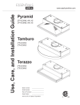
Pyramid
ZPY-E30AB, AW, AS
ZPY-E36AB, AW, AS
Tamburo
ZTA-E30AS
ZTA-E36AS
Terazzo
ZTE-E30AS
ZTE-E36AS
Model number:
Serial Number:
Date of Purchase:
Sales Dealer:
APR14.0901 © Zephyr Corporation
www.zephyronline.com
INSTALLATION
Ductwork Calculation Sheet ...................................
Mounting Height & Clearance................................
Ducting Options ...........................................................
6SHFL¿FDWLRQV ...............................................................
Preparing Electrical ....................................................
Preparing Ducting Location ....................................
Recirculating .................................................................
Optional Utensil Bar ...................................................
Mounting the Range Hood ......................................
5
6
7
8
9
10
11
12
13
CONTROLS
Slide Controls ............................................................... 14
MAINTENANCE
Cleaning and Filter Removal.................................. 15
Lights ................................................................................ 16
TROUBLESHOOTING................................................................ 17
WIRING DIAGRAMS ................................................................... 18
LIST OF PARTS AND ACCESSORIES .............................. 19
1
Table of Contents
SAFETY NOTICE ................................................................. 2-3
LIST OF MATERIALS....................................................... 4
www.zephyronline.com
Important Safety Notice
READ AND SAVE THESE INSTRUCTIONS
WARNING
TO REDUCE THE RISK OF FIRE OR ELECTRIC SHOCK, DO NOT USE THIS FAN WITH ANY SOLID-STATE CONTROL DEVICE.
WARNING
TO REDUCE THE RISK OF FIRE ELECTRIC SHOCK, OR INJURY TO PERSONS, OBSERVE THE FOLLOWING:
a. Use this unit only in the manner intended by the manufacturer, if you have questions, contact the manufacturer.
b. Before servicing or cleaning unit, switch power off at service panel and lock panel to prevent power from being switched on
accidentally. When the service disconnecting means cannot be locked, securely fasten a prominent warning device, such as a tag, to
the service panel.
CAUTION
For general ventilating use only. Do not use to exhaust hazardous or explosive materials and vapors. Take care when using cleaning
agents or detergents. Suitable for use in household cooking area.
WARNING
TO REDUCE THE RISK OF RANGE TOP GREASE FIRE:
a. Never leave surface units unattended at high settings. Boilovers cause smoking and greasy spillovers that may ignite. Heat oils slowly
on low or medium settings.
E $OZD\VWXUQKRRG21ZKHQFRRNLQJDWKLJKKHDWRUZKHQÀDPLQJIRRG
F &OHDQYHQWLODWLQJIDQVIUHTXHQWO\*UHDVHVKRXOGQRWEHDOORZHGWRDFFXPXODWHRQIDQRU¿OWHU
d. Use proper pan size. Always use cookware appropriate for the size of the surface element.
H .HHSIDQ¿OWHUVDQGJUHDVHODGHQVXUIDFHVFOHDQ
f. Use high setting on hood only when necessary.
g. Don’t leave hood unattended when cooking.
h. Always use cookware and utensils appropriate for the type of and amount of food being prepared.
WARNING
TO REDUCE THE RISK OF INJURY TO PERSONS IN THE EVENT OF A RANGE TOP FIRE, OBSERVE THE FOLLOWING:
D 6027+(5)/$0(6ZLWKDFORVH¿WWLQJOLGFRRNLHVKHHWRUPHWDOWUD\WKHQWXUQRIIWKHEXUQHU%(&$5()8/7235(9(17%8516
,IWKHÀDPHVGRQRWJRRXWLPPHGLDWHO\(9$&8$7($1'&$//7+(),5('(3$570(17
b. NEVER PICK UP A FLAMING PAN – You may be burned.
c. DO NOT USE WATER, including wet dishcloths or towels – a violent steam explosion will result.
d. Use an extinguisher ONLY if:
1. You know you have a Class ABC extinguisher, and you already know how to operate it.
7KH¿UHLVVPDOODQGFRQWDLQHGLQWKHDUHDZKHUHLWVWDUWHG
7KH¿UHGHSDUWPHQWLVEHLQJFDOOHG
<RXFDQ¿JKWWKH¿UHZLWK\RXUEDFNWRDQH[LW
WARNING
TO REDUCE THE RISK OF FIRE, ELECTRIC SHOCK OR INJURY TO PERSONS, OBSERVE THE FOLLOWING:
D ,QVWDOODWLRQZRUNDQGHOHFWULFDOZLULQJPXVWEHGRQHE\TXDOL¿HGSHUVRQVLQDFFRUGDQFHZLWKDOODSSOLFDEOHFRGHVDQGVWDQGDUGV
,QFOXGLQJ¿UHUDWHGFRQVWUXFWLRQ
E 6XI¿FLHQWDLULVQHHGHGIRUSRZHUFRPEXVWLRQDQGH[KDXVWLQJRIJDVHVWKURXJKWKHÀXHFKLPQH\RIIXHOEXUQLQJHTXLSPHQWWRSUHYHQW
back-drafting. Follow the heating equipment manufacturer’s guideline and safety standards such as those published by the National
)LUH3URWHFWLRQ$VVRFLDWLRQ1)3$DQGWKH$PHULFDQ6RFLHW\IRU+HDWLQJ5HIULJHUDWLRQDQG$LU&RQGLWLRQLQJ(QJLQHHUV$6+5$(DQG
the local code authorities.
c. When cutting or drilling into wall or ceiling, do not damage electrical wiring and other hidden utilities.
d. Ducted fans must always vent to the outdoors.
e. NEVER place a switch where it can be reached from a tub or shower.
f. Make sure the power is off before installing, wiring or maintenancing.
2
TO REDUCE THE RISK OF FIRE, USE ONLY METAL DUCTWORK.
CAUTION
7RUHGXFHULVNRI¿UHDQGWRSURSHUO\H[KDXVWDLURXWVLGH'RQRWYHQWH[KDXVWDLULQWRVSDFHVZLWKLQZDOOVFHLOLQJV
attics, crawl spaces or garages.
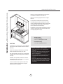
Maximum weight of shelf space is 5 lbs. Do not exeed weight limit of shelf. Do not place or store any combustible
materials on shelf.
For indoor use only.
Do not use over cooking equipment greater than 60,000 BTU/hr.
OPERATION
$OZD\VOHDYHVDIHW\JULOOHVDQG¿OWHUVLQSODFH:LWKRXWWKHVHFRPSRQHQWVRSHUDWLQJEORZHUVFRXOGFDWFKRQWRKDLU
¿QJHUVDQGORRVHFORWKLQJ
The manufacturer declines all responsibility in the event of failure to observe the instructions given here for installation,
maintenance and suitable use of the product. The manufacturer further declines all responsibility for injury due to
negligence and the warranty of the unit automatically expires due to improper maintenance.
*NOTE: Please check www.zephyronline.com for revisions before doing any custom work.
ELECTRICAL REQUIREMENTS
Important:
Observe all governing codes and ordinances.
It is the customer’s responsibility:
7RFRQWDFWDTXDOL¿HGHOHFWULFDOLQVWDOOHU
- To assure that the electrical installation is adequate and in conformance with National Electrical Code, ANSI/NFPA 70
latest edition* or CSA standards C22.1-94, Canadian Electrical Code, Part 1 and C22.2 No.0-M91 - latest edition** and
all local codes and ordinances.
,IFRGHVSHUPLWDQGDVHSDUDWHJURXQGZLUHLVXVHGLWLVUHFRPPHQGHGWKDWDTXDOL¿HGHOHFWULFLDQGHWHUPLQHWKDWWKH
ground path is adequate.
Do not ground to a gas pipe.
&KHFNZLWKDTXDOL¿HGHOHFWULFLDQLI\RXDUHQRWVXUHWKHUDQJHKRRGLVSURSHUO\JURXQGHG
Do not have a fuse in the neutral or ground circuit.
*National Fire Protection Association Batterymarch Park, Quincy, Massachusetts 02269
** CSA International 8501 East Pleasant Valley Road, Cleveland, Ohio 44131-5575
This appliance requires a 120V 60Hz electrical supply and connected to an individual properly grounded branch circuit
protected by a 15 or 20 ampere circuit breaker or time delay fuse. Wiring must be 2 wire with ground. Please also refer
to Electrical Diagram on product.
$FDEOHORFNLQJFRQQHFWRUQRWVXSSOLHGPLJKWDOVREHUHTXLUHGE\ORFDOFRGHV&KHFNZLWKORFDOUHTXLUHPHQWVSXUFKDVH
and install appropriate connector if necessary.
3
Important Safety Notice
WARNING
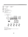
List of Materials
www.zephyronline.com
MODELS: ZPY-E30AB, AW, AS
ZTA-E30AS
ZTE-E30AS
ZPY-E36AB, AW, AS
ZTA-E36AS
ZTE-E36AS
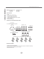
PARTS SUPPLIED
1 - Hood
$OXPLQXPPHVK¿OWHUV
+DORJHQOLJKWEXOEVpre-installed
1 - 7” round transition collar
1 - 3 1/4” x 10” rectangular collar with damper
1 - Utensil bar
1 - Hardware package
HARDWARE PACKAGE CONTENTS
Suction Cup (1)
For Light Bulb Installation and Removal
M4 x 1-1/4” (4)
M4 x 3/4” (4)
M4 x 8 (2)
For Utensil Bar
Wire Caps (3)
S Hooks (5 - 30” Models, 6 - 36” Models)
PARTS NOT SUPPLIED
- Ducting, conduit and all installation tools
3KLOLSVKHDGVFUHZGULYHUZLWKPLQLPXP´ORQJVKDIWrequired to install ZPY-E30
&DEOHORFNif required by local codes
- Recirculating kit
4
M4 x 8 (6)
Equivalent number
length x used
=
Duct pieces
Total
Total
3-1/ 4” x 10” 1 Ft.
Rect.,
straight
x(
) =
Ft.
6”- 8” Round 30 Ft.
wall cap
with damper
x(
) =
Ft.
7” Round,
straight
1 Ft.
x(
) =
Ft.
6”- 8” Round, 30 Ft.
roof cap
x(
) =
Ft.
8” Round,
straight
1 Ft.
x(
) =
Ft.
6” round to
1 Ft.
3-1/ 4” x 10”
rect.
transition
x(
) =
Ft.
3-1/ 4” x 10” 15 Ft.
Rect. 90 0
elbow
x(
) =
Ft.
x(
) =
Ft.
3-1/ 4” x 10” 9 Ft.
Rect. 45 0
elbow
x(
) =
Ft.
6” round to
16 Ft.
3-1/ 4” x 10”
rect.
transition
90 0 elbow
7” or 8”
Round,
90 0 elbow
15 Ft.
x(
) =
Ft.
3-1/ 4” x 10” 24 Ft.
Rect. 90 0
flat elbow
x(
7” or 8”
Round,
45 0 elbow
9 Ft.
x(
) =
Ft.
3-1/ 4” x 10” 30 Ft.
Rect.
wall cap
with damper
x(
7” or 8”
30 Ft.
Round
wall cap
with damper
x(
) =
Ft.
3-1/ 4” x 10” 5 Ft.
Rect. to
6” round
transition
x(
) =
Ft.
7” or 8”
Round,
roof cap
x(
) =
Ft.
3-1/ 4” x 10” 20 Ft.
Rect. to
6” round
transition
90 0 elbow
x(
) =
Ft.
7” round to
8 Ft.
3 1/ 4” x 10”
rect.
transition
x(
) =
Ft.
) =
Ft.
15 Ft.
x(
) =
Ft.
7” round to
23 Ft.
3-1/ 4” x 10”
rect.
transition
90 0 elbow
x(
6” Round,
90 0 elbow
6” Round,
45 0 elbow
9 Ft.
x(
) =
Ft.
Subtotal column 2 =
Ft.
Subtotal column 1 =
Ft.
Total ductwork
Ft.
) =
) =
Subtotal column 1 =
Ft.
Ft.
Ft.
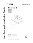
Maximum Duct Length: For satisfactory air movement,
the total duct length should not exceed 100 equivalent feet.
5
30 Ft.
=
Installation – Ductwork Calculation Sheet
Equivalent number
length x used
=
Duct pieces
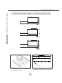
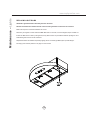
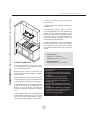
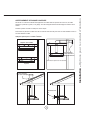
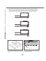
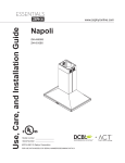
Installation – Mounting Height & Clearance
www.zephyronline.com
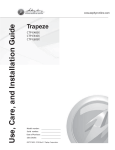
Minimum mounting height between range top to
hood bottom should be no less than 24”.
Maximum mounting height should be no higher
than 32”.
It is important to install the hood at the proper
mounting height. Hoods mounted too low could
UHVXOWLQKHDWGDPDJHDQG¿UHKD]DUGZKLOHKRRGV
mounted too high will be hard to reach and will
ORVHLWVSHUIRUPDQFHDQGHI¿FLHQF\
in.
” max.
4
2 m
”
32
If available, also refer range manufacturer’s height
clearance requirements and recommended hood
mounting height above range.
36”
Vertical Ducting:
7” round minimum or
3-1/4” x 10” rectangular minimum
Horizontal Ducting:
3-1/4”x10” rectangular minimum
DUCTING
A minimum of 7” round or 3-1/4” x 10” rectangular
GXFWPXVWEHXVHGWRPDLQWDLQPD[LPXPDLUÀRZ
HI¿FLHQF\
DAMAGE-SHIPMENT / INSTALLATION:
3OHDVHIXOO\LQVSHFWXQLWIRUGDPDJHEHIRUH
installation.
,IWKHXQLWLVGDPDJHGLQVKLSPHQWUHWXUQWKH
unit to the store in which it was bought for
repair or replacement.
,IWKHXQLWLVGDPDJHGE\WKHFXVWRPHUUHSDLU
or replacement is the responsibility of the
customer.
,IWKHXQLWLVGDPDJHGE\WKHLQVWDOOHULIRWKHU
WKDQWKHFXVWRPHUUHSDLURIUHSODFHPHQWPXVW
be made by arrangement between customer
and installer.
Always use rigid type metal ducts only. Flexible
GXFWVFRXOGUHVWULFWDLUÀRZE\XSWR
$OVRXVHFDOFXODWLRQRQSDJHWRFRPSXWHWRWDO
available duct run when using elbows, transitions
and caps.
ALWAYS, when possible, reduce the number or
transitions and turns. If long duct run is required,
increase duct size from 7” to 8”.
If turns or transitions are required; install as far
away from hood duct output and as far apart,
between the two as possible.
6
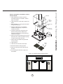
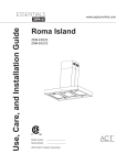
NEVER exhaust air or terminate duct work into spaces between walls, crawl spaces, ceiling, attics or garages.
All exhaust must be ducted to the outside.
Use metal ductwork only.
)DVWHQDOOFRQQHFWLRQVZLWKVKHHWPHWDOVFUHZVDQGWDSHDOOMRLQWVZLWKFHUWL¿HG6LOYHU7DSHRU'XFW7DSH
Some Ducting Options
ductless
recirculating
Tamburo & Terazzo
Side wall cap
w/ gravity damper
Soffit or crawl space
Pyramid
Roof Pitch w/
Flashing & Cap
Rear Ducting
7
Installation – Ducting Options
WARNING FIRE HAZARD
www.zephyronline.com
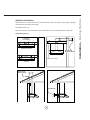
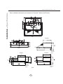
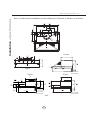
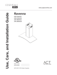
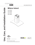
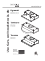
Installation – 6SHFL¿FDWLRQV
Note: Installation dimensions are the same for Pyramid, Tamburo and Terazzo
15
15
29 16 " or 35 16 "
3
1
25 16 " or 31 8 "
2"
11
8 16 "
15
9 16 "
1"
5
1
48" 34"
1
15 "
16
elec. k/o
8"
6 1
16 5
"
CL
Top
Pyramid
3
1 16 "
11
8 16 "
15
9 16 "
7
16"
12"
1
34"
elec. k/o
3
78"
"
8 1 . 10 14"
4
CL
9
1 16 "
Back
21"
Terazzo
Tamburo
12"
9
16 "
9
1 16 "
12"
5
7 8 "
3
7 8 "
3
3 8 "
1
21 8 "
Adjustable
Utensil Rail
Heights
1
1
8 4 " 104 "
3
4 4"
"
1"
8 1 . 10 4
4
3
2 4"
21
Adjustable
Utensil Rail
Heights
1
8 "
Adjustable
Utensil Rail
Heights
Side
8
WARNING
$OO(OHFWULFDOZRUNPXVWE\SHUIRUPHGE\TXDOL¿HGHOHFWULFLDQRUSHUVRQZLWKVLPLODUWHFKQLFDO
knowledge and background.
For personal safety, remove house fuse or open circuit breaker before beginning installation. Do not use
extension cord or adapter plug with this appliance.
Follow national electrical codes or prevailing local codes and ordinances.
Electrical Supply:
This appliance requires a 120V 60Hz electrical supply, and connected to an individual, properly
grounded branch circuit, protected by a 15 or 20 ampere circuit breaker or time delay fuse. Wiring must
be 2 wire w/ ground. Please refer to Electrical Diagram labeled on product.
Cable Lock:
$FDEOHORFNLQJFRQQHFWRUQRWVXSSOLHGPLJKWDOVREHUHTXLUHGE\ORFDOFRGHV&KHFNZLWKORFDO
requirements and codes, purchase and install appropriate connector if necessary.
ZPY-ExxAx, ZTA-ExxAS and ZTE-ExxAS - 207 Watts, 2 Amps.
ZPY-ExxAx290, ZTA-ExxAS290 and ZTE-ExxAS290 - 186 Watts, 2 Amps.
Cable Lock
9
Installation – Preparing Electrical
ELECTRICAL
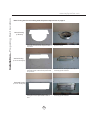
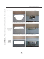
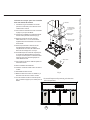
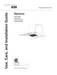
Installation – Preparing Duct Location
www.zephyronline.com
Note: If using hood in recirculating mode skip these steps and turn to page 11.
1
Vertical Ducting
5RXQG
6
2
5
3
4
8VLQJDÀDWKHDGVFUHZGULYHUUHPRYHERWKWKH 6HFXUHURXQGFROODUWRWRSRIKRRGXVLQJ
rectangular and round knock-out plates located on 0[VFUHZV
top of hood
3
4
5
2
Vertical Ducting
6
1
[5HFWDQJXODU
8VLQJDÀDWKHDGVFUHZGULYHUUHPRYHRQO\WKH
rectangular section of the knock-out plate located
on top of hood.
Horizontal Ducting
6HFXUH[UHFWDQJXODUFROODUWRWRSRI
KRRGXVLQJ0[VFUHZV
4
1
[5HFWDQJXODU
2
8VLQJDÀDWKHDGVFUHZGULYHUUHPRYHWKH
rectangular knock-out plate located on back of
hood.
10
3
5
6
6HFXUH[UHFWDQJXODUFROODUWREDFNRI
KRRGXVLQJ0[VFUHZV
front slot
back slot
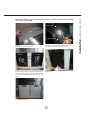
)RU7DPEXUR=7$DQG7HUD]]R=7(RQO\
Unscrew and remove the front cover
FKDUFRDO¿OWHU
bracket
metal air
diverter
plate
1. Remove air diverter plate slot covers. Remove metal
air diverter plate from front slot and re-position to back
slot. Re-install air diverter plate covers.
FKDUFRDO¿OWHU
bracket
center
panel
8VLQJFRPSRQHQWVIURP=5&LQVWDOO
FKDUFRDO¿OWHUEUDFNHWVDQGFHQWHUSDQHOWR
ERWWRPRIWKHKRRGZLWKVFUHZVIRUHDFK
component. Screws are pre-installed to the hood.
5HPRYHVFUHZV¿UVWWRLQVWDOOEUDFNHWVDQGFHQWHU
panel then re-install screws..
,QVWDOOFKDUFRDO¿OWHUVLQWRFKDUFRDO¿OWHUEUDFNHWV
,QVWDOOWKHPHVK¿OWHUV
11
Installation – Recirculating
Note: To use hood in air recirculating mode please purchase recirculating kit ZRC-0200
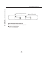
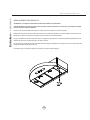
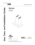
Installation – Optional Utensil Bar
www.zephyronline.com
1RWH8WHQVLOEDULVGHVLJQHGIRUXVHZKHQKRRGLVLQVWDOOHGXQGHUDGHHSFDELQHW7KHUH
are 3 height options for installing the utensil bar. Install utensil bar and adjust the height
before mounting the hood. Utensil bar should press against the wall when hood is installed.
S-Hooks
Fig 1
6HFXUHXWHQVLOEDUWREDFNRIKRRGXVLQJ
M4 x 8 utensil bar screws
12
Fig 2
2. Install optional s hooks used to hang utensils.
8. Electrical
6HOHFWSUHIHUUHGGXFWORFDWLRQYHUWLFDORU
KRUL]RQWDOLIGXFWLQJRXWRINLWFKHQ5HIHUWR
page 10 for details.
6. Duct
opening/
cutout
2. Install utensil bar to hood. Refer to page 12 for
details.
%HJLQLQVWDOODWLRQE\UHPRYLQJWKHPHVK¿OWHUV
DQGOLJKWSDQHOV)LJ
9. Aluminum duc
tape
4. Reinforce cabinet with 1”x2” wood strips
if additional strengthening is required or if
cabinets are framed.
4. Add 1”x2”
wood strips
5. Temporarily position the range hood in the
desired mounting location. Measure and
mark the mounting holes, duct and electrical
locations with a pencil.
6. Drill/cut out the required openings for duct and
electrical access; make sure the duct opening
is large enough to apply duct tape.
)DVWHQKRRGRQWRFDELQHWZLWK0ZRRG
screws provided.
8. Install electrical.
2. Mesh
filters
9. Install duct work and seal with duct tape.
5HLQVWDOOPHVK¿OWHUVDQGOLJKWSDQHOV
11. Power up hood and check for leaks around
duct tape.
12. If recirculating the hood refer to page 11 for
more details.
Fig 3
Push in on panel latch then pull panel down
Fig 4
13
Installation – Mounting the Range Hood
Hood is designed for installation under a
kitchen cabinet
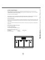
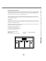
Controls – Slide Controls
www.zephyronline.com
1 Blower On/Off Speed Selection
III
II
I
2 Lights Off/Dim/Bright
II
0
1 BLOWER ON/OFF/SPEED SELECTION
0 is off, I is low speed, II is medium speed and III is high speed.
2 LIGHTS OFF/BRIGHT/DIM
0 is off, I is dim, and II is bright.
14
I
0
Clean the hood surface periodically with hot soapy water and clean cotton cloth. Do not use corrosive or
abrasive detergent, or steel wool/scouring pads which will scratch and damage surface. Do not use products
containing chlorine bleach or orange cleaners.
For heavier soil use liquid degreaser.
After cleaning, you may use non-abrasive stainless steel polish/ cleaners, to polish and buff out the stainless
OXVWHUDQGJUDLQ$OZD\VVFUXEOLJKWO\XVLQJDPLFUR¿EHURUFOHDQFRWWRQFORWKDQGZLWKJUDLQ
Aluminum Mesh Filters
7KHDOXPLQXPPHVK¿OWHUVDUHLQWHQGHGWRWUDSUHVLGXHDQGJUHDVHIURPFRRNLQJ$OWKRXJKWKHDOXPLQXPPHVK
¿OWHUVVKRXOGQHYHUQHHGUHSODFLQJWKH\DUHUHTXLUHGWREHFOHDQHGHYHU\GD\VRUPRUHRIWHQGHSHQGLQJRQ
cooking habits.
)LOWHUVPD\EHSODFHGLQGLVKZDVKHUDWORZKHDWRUVRDNHGLQKRWVRDS\ZDWHU'U\¿OWHUVDQGUHLQVWDOOEHIRUH
using hood.
Removing Aluminum Mesh Filters (Fig 5)
3XVKLQRQ¿OWHUKDQGOHV
3LYRWIURQWRI¿OWHUGRZQZDUG
5HPRYH¿OWHUE\SXOOLQJDZD\IURPKRRG
Replacing Aluminum Mesh Filters
Hood Model:
Part No.
All models and sizes
50200030
Qty. to Order.
2
Fig 5
15
Maintenance – Cleaning and Filter Removal
SURFACE MAINTENANCE:
Maintenance – Lights
www.zephyronline.com
REPLACING LIGHT BULBS
CAUTION: Light bulb becomes extremely hot when turned on.
DO NOT touch bulb until switched off and cooled. Touching hot bulbs could cause serious burns.
Make sure all power is turned off and bulbs are not hot.
Remove by turning bulb counter clockwise. Note: Bulb does not unscrew; it turns 60 degrees, stops and falls out.
,IEXOEVDUHGLI¿FXOWWRWXUQGXHWRSURORQJHGXVH¿UPO\DWWDFKVXFWLRQFXSLQFOXGHGLQKDUGZDUHSDFNDJHRUXVHD
rubber/latex glove and turn counter clockwise.
5HSODFHPHQWEXOEVDUHDYDLODEOHDWVSHFLDOW\OLJKWLQJVWRUHV3XUFKDVHW\SH05*8:KDORJHQ
For Zephyr part numbers please turn to page 19 of the manual.
16
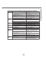
Issue
Cause
After installation,
the unit doesn’t
work.
1. The power source is not turned ON.
Light works, but
blower is not
turning.
The unit is
vibrating.
The unit is
whistling.
The blower is
working, but the
lights are not.
The hood is
not venting out
properly.
Mesh Filter is
vibrating.
What to do
1. Make sure the circuit breaker and the unit’s
power is ON.
2. The power line and the cable locking connector is 2. Check the power connection with the unit is
not connecting properly.
connected properly.
3. The switch or control board wirings are
3. Make sure the wirings at the switch or control
disconnected.
board are connected properly.
4. The wires on control board or switch are loose.
4. Make sure the wires on the control board or
switch are connected properly.
5. The switch or control board is defective.
5. Change the switch or control board.
1. The blower is defective, possible seized.
1. Change the blower.
2. The thermally protected system detects if the
2. The blower will function properly after the
blower is too hot to operate and shuts the blower
thermally protected system cool down.
down.
3. Damaged capacitor.
3. Change the capacitor.
4. The control board or blower switch is defective.
4. Change the control board or blower switch.
1. The blower is not secure in place.
1. Tighten the blower in place.
2. Damaged blower wheel.
2. Change the blower wheel.
3. The hood is not secured in place.
3. Check the installation of the hood.
7KH¿OWHULVQRWLQWKHFRUUHFWSRVLWLRQ
$GMXVWWKH¿OWHUVXQWLOWKHZKLVWOLQJVWRSV
2. The duct pipe connections are not sealed or
2. Check the duct pipe connections to be sure all
connected properly.
connections are sealed properly.
1. Defective bulb.
1. Change the bulb.
2. The light bulb is loose.
2. Tighten the light bulb.
3. The light bulb plug is disconnected.
3. Connect the light bulb plug.
1. The hood might be hanging to high from the cook 1. Adjust the distance between the cook top and
top.
the bottom of the hood within 24” and 32”
range.
2. The wind from the opened windows or opened
2. Close all the windows and doors to eliminate
doors in the surrounding area are affecting the
WKHRXWVLGHZLQGÀRZ
ventilation of the hood.
3. Blockage in the duct opening or duct work.
3. Remove all the blocking from the duct work or
duct opening.
4. The direction of duct opening is against the wind. 4. Adjust the duct opening direction.
5. Using the wrong size of ducting.
5. Change the ducting to correct size.
0HVK¿OWHULVORRVH
1. Make sure the metal clips in the handle are not
VWXFN2UUHSODFHWKHPHVK¿OWHU
2. Filter sping clip is broken.
8QLQVWDOODQGUHLQVWDOO¿OWHUSXVKXSRQ¿OWHU
ODWFK5HSODFHPHVK¿OWHULIQHHGHG
17
Troubleshooting
TROUBLESHOOTING PROCEDURES FOR PYRAMID, TAMBURO AND TERAZZO
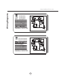
Wiring Diagrams
www.zephyronline.com
ZPY-E30/36AS
ZTA-E30/36AS
Model: ZTE-E30/36AS
Voltage: 120V 60Hz
Power consumption
Total:Max. 207W @ 2 A
Lamp:
Max. 50Wx2
Fan:
Max. 107W
182766
THERMALLY PROTECTED
! ZPY-E30/36AS290
182766 ZTA-E30/36AS290
Model: ZTE-E30/36AS290
Voltage: 120V 60Hz
Power consumption
Total:Max. 186W @ 2 A
Lamp:
Max. 50Wx2
Fan:
Max. 86W
THERMALLY PROTECTED
! 18
PART #
Replacement Parts
/LJKW%XOE05*8:HDFK
0HVK)LOWHU$OO0RGHOVHDFK
=%
Optional Accessories
Recirculating Kit, All Models
&KDUFRDO)LOWHU5HSODFHPHQWHDFK
ZRC-0200
=)&
To order parts, visit us online at http://store.zephyronline.com or call us at 1.888.880.8368
19
List of Parts and Accessories
DESCRIPTION
STAPLE YOUR RECEIPT HERE
Proof of the original purchase
date is needed to obtain
service under warranty
Limited Warranty
TO OBTAIN SERVICE UNDER WARRANTY OR FOR ANY SERVICE RELATED QUESTIONS, please call:
1-888-880-8368
Zephyr Corporation (referred to herein as “we” or “us”) warrants to the original consumer purchaser (referred to herein
as “you” or “your”) of Zephyr products (the “Products”) that such Products will be free from defects in materials or workmanship as follows:
Three Year Limited Warranty for Parts: For three years from the date of your original purchase of the Products, we
will provide, free of charge, Products or parts (including LED light bulbs, if applicable) to replace those that failed due to
manufacturing defects. We may choose, in our sole discretion, to repair or replace parts before we elect to replace the
Products.
One Year Limited Warranty for Labor: For one year from the date of your original purchase of the Products, we will
provide, free of charge, the labor cost associated with repairing the Products or parts to replace those that failed due to
manufacturing defects. After the first year from the date of your original purchase, you are responsible for all labor costs
associated with this warranty.
Warranty Exclusions: This warranty covers only repair or replacement, at our option, of defective Products or parts
and does not cover any other costs related to the Products including but not limited to: (a) normal maintenance and
service required for the Products and consumable parts such as incandescent or halogen light bulbs, metal and carbon
filters and fuses; (b) any Products or parts which have been subject to freight damage, misuse, negligence, accident,
faulty installation or installation contrary to recommended installation instructions, improper maintenance or repair (other
than by us); (c) commercial use of the Products or use otherwise inconsistent with its intended purpose; (d) natural wear
of the finish of the Products or wear caused by improper maintenance, use of corrosive and abrasive cleaning products,
pads, and oven cleaner products; (e) chips, dents or cracks caused by abuse or misuse of the Products; (f) service trips
to your home to teach you how to use the Products; or (g) damage to the Products caused by accident, fire, floods or act
of God. If you are outside our service area, additional charges may apply for shipping costs for warranty repair at our
designated service locations and for the travel cost to have a service technician come to your home to repair, remove or
reinstall the Products. After the first year from the date of your original purchase, you are also responsible for all labor
costs associated with this warranty.
Limitations of Warranty. OUR OBLIGATION TO REPAIR OR REPLACE, AT OUR OPTION, SHALL BE YOUR SOLE
AND EXCLUSIVE REMEDY UNDER THIS WARRANTY. WE SHALL NOT BE LIABLE FOR INCIDENTAL, CONSEQUENTIAL OR SPECIAL DAMAGES ARISING OUT OF OR IN CONNECTION WITH THE USE OR PERFORMANCE OF
THE PRODUCTS. THE EXPRESS WARRANTIES IN THE PRECEDING SECTION ARE EXCLUSIVE AND IN LIEU OF
ALL OTHER EXPRESS WARRANTIES. WE HEREBY DISCLAIM AND EXCLUDE ALL OTHER EXPRESS WARRANTIES FOR THE PRODUCTS, AND DISCLAIM AND EXCLUDE ALL WARRANTIES IMPLIED BY LAW, INCLUDING
THOSE OF MERCHANTABILITY AND FITNESS FOR A PARTICULAR PURPOSE. Some states or provinces do not
allow limitations on the duration of an implied warranty or the exclusion or limitation of incidental or consequential damages, so the above limitations or exclusions may not apply to you. To the extent that applicable law prohibits the exclusion of implied warranties, the duration of any applicable implied warranty is limited to the same two-year period
described above. Any oral or written description of the Products is for the sole purpose of identifying the Products and
shall not be construed as an express warranty. Prior to using, implementing or permitting use of the Products, you shall
determine the suitability of the Products for the intended use, and you shall assume all risk and liability whatsoever in
connection with such determination. We reserve the right to use functionally equivalent refurbished or reconditioned
parts or Products as warranty replacements or as part of warranty service. This warranty is not transferable from the
original purchaser and applies in the United States and Canada.
To Obtain Service Under Limited Warranty: To qualify for warranty service, you must: (a) notify us at the address or
telephone number stated below within 60 days of the discovery of the defect; (b) give the model number and part identification number and serial number; and (c) describe the nature of any defect in the Product or part. At the time of the
request for warranty service, you must present evidence of your proof of purchase and proof of the original purchase
date. If we determine that the warranty exclusions listed above apply or if you fail to provide the necessary documentation to obtain service, you will be responsible for all shipping, travel, labor and other costs related to the services.
Please check our website for any revisions, www.zephyronline.com.
MAY13.0301
Guide d’utilisation, d’entretien et d’installation
www.zephyronline.com
Pyramid
ZPY-E30AB, AW, AS
ZPY-E36AB, AW, AS
Tamburo
ZTA-E30AS
ZTA-E36AS
Terazzo
ZTE-E30AS
ZTE-E36AS
Numéro de modèle :
Numéro de série :
Date d’achat :
Détaillant :
APR14.0901 © Zephyr Corporation
www.zephyronline.com
INSTALLATION
Feuille de calcul pour le conduit ..........................
Espace libre et hauteur de montage ...................
Options d’installation pour le conduit ..................
6SpFL¿FDWLRQV ...............................................................
Préparation de l’électricité ......................................
Préparation pour l’installation du conduit ..........
Reprise d’air ..................................................................
Barre à ustensiles optionnelle ...............................
Montage de la hotte ...................................................
5
6
7
8
9
10
11
12
13
COMMANDES
Réglage par curseur .................................................. 14
ENTRETIEN
1HWWR\DJHHWFKDQJHPHQWGHV¿OWUHV .................. 15
Lumières ......................................................................... 16
DÉPANNAGE ................................................................................. 17
SCHÉMA DE CÂBLAGE ........................................................... 18
LISTES DES ACCESSOIRES ET DES PIÈCES ............ 19
1
Table des matières
MISE EN GARDE DE SÉCURITÉ.......................... 2-3
LISTE DU MATÉRIEL ....................................................... 4
www.zephyronline.com
Mise en garde de sécurité
LISEZ ET CONSERVEZ CES INSTRUCTIONS
AVERTISSEMENT
POUR RÉDUIRE LES RISQUES D’INCENDIE OU DE DÉCHARGE ÉLECTRIQUE, N’UTILISEZ PAS CET APPAREIL AVEC UN TABLEAU DE
COMMANDE À SEMI-CONDUCTEURS.
AVERTISSEMENT
POUR RÉDUIRE LES RISQUES D’INCENDIE, DE DÉCHARGE ÉLECTRIQUE OU DE BLESSURE, RESPECTEZ CES CONSIGNES :
a. N’utilisez cet appareil que de la manière prévue par le fabricant. Si vous avez des questions, communiquez avec le fabricant.
b. Avant de procéder au nettoyage ou à l’entretien de l’appareil, éteignez l’alimentation du panneau électrique et bloquez le dispositif de
déconnexion pour éviter que l’alimentation électrique ne soit accidentellement rallumée. Si le dispositif de sectionnement d’électricité ne
peut être bloqué, attachez un avertissement (comme une étiquette) bien en vue sur le tableau électrique.
ATTENTION
Pour ventilation générale seulement. N’utilisez pas cet appareil pour évacuer des vapeurs et des matériaux explosifs ou dangereux. Prenez
garde lors de l’utilisation d’agents nettoyants ou de détergents. Ne devrait être utilisé que dans la cuisine de votre maison.
AVERTISSEMENT
POUR RÉDUIRE LES RISQUES DE FEU DE GRAISSE SUR LA SURFACE DE CUISSON :
a. Ne laissez jamais l’appareil sans surveillance lors de son utilisation à haute température. Les débordements par bouillonnement causent de
la fumée et des déversements de graisse qui peuvent prendre feu. Faites chauffer l’huile à des températures basses ou moyennes.
E $OOXPH]WRXMRXUVODKRWWHORUVTXHYRXVFXLVLQH]jKDXWHWHPSpUDWXUHRXTXHYRXVIDLWHVÀDPEHUGHVDOLPHQWV
F 1HWWR\H]IUpTXHPPHQWOHVYHQWLODWHXUVGHODKRWWH/DJUDLVVHQHGHYUDLWMDPDLVV¶DFFXPXOHUGDQVOHVYHQWLODWHXUVRXOHV¿OWUHV
d. Utilisez des poêlons aux dimensions adéquates. Utilisez toujours une batterie de cuisine correspondant aux dimensions de l’élément.
H $VVXUH]YRXVTXHOHYHQWLODWHXUOHV¿OWUHVHWOHVVXUIDFHVRODJUDLVVHSRXUUDLWV¶DFFXPXOHUVRQWWRXMRXUVSURSUHV
f. Utilisez le réglage haut de la hotte seulement lorsque nécessaire.
g. Ne laissez pas la hotte sans surveillance lorsque vous cuisinez.
h. Utilisez toujours une batterie de cuisine et des ustensiles convenant au type et à la quantité de nourriture que vous préparez.
AVERTISSEMENT
POUR RÉDUIRE LES RISQUES DE BLESSURE LORS D’UN INCENDIE SUR LA SURFACE DE CUISSON :
a. ÉTOUFFEZ LES FLAMMES avec un couvercle, une plaque à biscuits ou un plateau de métal et éteignez ensuite le brûleur. PRENEZ
*$5'($8;5,648(6'(%5Ó/85(6LOHVÀDPPHVQHGLVSDUDLVVHQWSDVe9$&8(=/(6/,(8;(7$33(/(=/(6(59,&(
D’INCENDIE.
b. NE PRENEZ JAMAIS UN POÊLON EN FEU – Vous pourriez vous brûler.
c. N’UTILISEZ PAS D’EAU, ou un linge à vaisselle mouillé – une violente explosion de vapeur s’ensuivra.
d. Utilisez un extincteur SEULEMENT si :
1. Vous savez que vous possédez un extincteur de classe ABC et vous savez vous en servir.
2. Le feu est faible et ne s’est pas répandu depuis son point d’origine.
3. Vous avez appelé le service d’incendie.
9RXVSRXYH]VRUWLUIDFLOHPHQWGHO¶HQGURLWRYRXVFRPEDWWH]OHIHX
AVERTISSEMENT
POUR RÉDUIRE LES RISQUES D’INCENDIE, DE DÉCHARGE ÉLECTRIQUE OU DE BLESSURE, SUIVEZ LES CONSIGNES SUIVANTES :
D /HVWUDYDX[G¶LQVWDOODWLRQHWGHFkEODJHpOHFWULTXHGRLYHQWrWUHIDLWVSDUXQHSHUVRQQHTXDOL¿pHVHORQOHVVWLSXODWLRQVGHWRXVOHVQRUPHVHW
standards en vigueur, dont les normes des constructions ayant une cote de résistance au feu.
b. Pour prévenir les contre-explosions, une certaine quantité d’air est nécessaire pour la combustion et l’évacuation des gaz par le carneau
(cheminée) de l’appareil de combustion. Respectez les directives du fabricant d’outillage de chauffage et les normes de sécurité comme
celles publiées par la NFPA (Association nationale des services d’incendie), par la Société américaine des ingénieurs en chauffage,
réfrigération et climatisation (ASHRAE) et par les normes des autorités locales.
c. Lorsque vous coupez ou percez un mur ou un plafond, assurez-vous de ne pas endommager le câblage électrique ou toute autre
installation technique dissimulée.
d. Les ventilateurs canalisés doivent toujours évacuer l’air à l’extérieur.
e. N’installez JAMAIS un interrupteur à une distance atteignable depuis un bain ou une douche.
f. Assurez-vous que l’alimentation électrique est éteinte avant de procéder à l’installation, au câblage ou à l’entretien de l’appareil
2
POUR RÉDUIRE LES RISQUES D’INCENDIE, N’UTILISEZ QUE DES CONDUITS D’AÉRATION EN MÉTAL..
ATTENTION
Pour réduire les risques d’incendie et pour évacuer l’air convenablement, assurez-vous de canaliser l’air à l’extérieur de
la maison. N’installez pas l’échappement du conduit dans les espaces entre les murs, le plafond, le grenier, les vides
sanitaires ou le garage.
Le poids maximal que peut soutenir l’étagère est 5 livres. Veuillez respecter cette limite de poids. Ne mettez pas et
n’entreposez pas de matières combustibles sur l’étagère.
Pour utilisation à l’intérieur seulement
Ne pas utiliser sur d’équipement de cuisson qui est supérieure à 60 000 BTU/h.
FONCTIONNEMENT
/DLVVH]WRXMRXUVOHVJULOOHVGHVUHWpHWOHV¿OWUHVHQSODFH6DQVFHVpOpPHQWVOHVYHQWLODWHXUVHQPDUFKH
SRXUUDLHQWDFFURFKHUGHVFKHYHX[GHVGRLJWVRXGHVYrWHPHQWVDPSOHV
/HIDEULFDQWVHGpJDJHGHWRXWHUHVSRQVDELOLWpGDQVOHVFDVGHQRQUHVSHFWGHVLQVWUXFWLRQVWUDQVPLVHVGDQV
OHSUpVHQWPDQXHOSRXUO¶LQVWDOODWLRQO¶HQWUHWLHQHWO¶XWLOLVDWLRQDGpTXDWHGXSURGXLW/HIDEULFDQWVHGpJDJH
pJDOHPHQWGHWRXWHUHVSRQVDELOLWpSRXUGHVEOHVVXUHVTXLUpVXOWHUDLHQWGHODQpJOLJHQFHORUVGHO¶XWLOLVDWLRQ'H
SOXVODJDUDQWLHSUHQG¿QDXWRPDWLTXHPHQWORUVGHO¶HQWUHWLHQLQDSSURSULpGHO¶DSSDUHLO
127(9HXLOOH]FRPPXQLTXHUDYHFQRXVRXYLVLWH]OHZZZ]HSK\URQOLQHFRPSRXUREWHQLUGHVUpYLVLRQVDYDQW
GHSURFpGHUjGHVWUDYDX[VXUFRPPDQGH
EXIGENCES ÉLECTRIQUES
,PSRUWDQW
Respectez tous les codes et règlements en vigueur.
Il est de la responsabilité du client de :
&RPPXQLTXHUDYHFXQLQVWDOODWHXUpOHFWULFLHQTXDOL¿p
- S’assurer que l’installation électrique est adéquate et qu’elle respecte le Code national de l’électricité, la plus récente
édition* du ANSI/NFPA 70 ou des normes du CSA C22.1-94, le Code canadien de l’électricité, section 1, la plus
récente édition** du code C22.2 No.0-M91 ainsi que tous les codes et règlements en vigueur.
6LOHVFRGHVSHUPHWWHQWO¶XWLOLVDWLRQG¶XQ¿OGHJDUGHLVROpHWTXHYRXVHQXWLOLVH]XQLOHVWUHFRPPDQGpTX¶XQpOHFWULFLHQ
TXDOL¿pGpWHUPLQHVLOHFKHPLQHPHQWGX¿OHVWDGpTXDW
N’effectuez pas la mise à la terre à un tuyau de gaz.
'HPDQGH]jXQpOHFWULFLHQTXDOL¿pVLYRXVQ¶rWHVSDVFHUWDLQTXHODKRWWHDpWpPLVHjODWHUUHDGpTXDWHPHQW
N’introduisez aucun fusible dans le circuit neutre ou de mise à la terre.
*National Fire Protection Association Batterymarch Park, Quincy, Massachusetts 02269
*National Fire Protection Association Batterymarch Park, Quincy, Massachusetts 02269
** CSA International 8501 East Pleasant Valley Road, Cleveland, Ohio 44131-5575
Cet appareil requiert une alimentation électrique de 120V 60Hz. Il doit être connecté à un circuit terminal individuel
dûment mis à la terre, protégé par un disjoncteur de circuit ou un fusible temporisé de 15 ou 20 ampères. Le câblage doit
FRPSWHU¿OVDYHFPLVHjODWHUUH9HXLOOH]YRXVUpIpUHUDX'LDJUDPPHpOHFWULTXHpWLTXHWpVXUO¶DSSDUHLO
Un raccord de câble (non inclus) pourrait également être exigé par les normes et réglementations locales. Informez-vous
des exigences et des normes locales. Achetez et installez le connecteur approprié si nécessaire.
3
Mise en garde de sécurité
ATTENTION
Liste du matériel
www.zephyronline.com
MODELS: ZPY-E30AB, AW, AS
ZTA-E30AS
ZTE-E30AS
ZPY-E36AB, AW, AS
ZTA-E36AS
ZTE-E36AS
PARTS SUPPLIED
1 - Hotte
2 - Filtres à tamis en aluminium (2)
2 - Ampoules halogènes (préinstallées)
1 - Collier de transition circulaire de 7”
1 - Collier rectangulaire de 3¼” x 10” avec registre
1 - Barre à ustensiles
1 - Trousse de quincaillerie
CONTENU DE LA TROUSSE DE QUINCAILLERIE
(1) Ventouse
Pour installer et enlever les ampoules
(4) M4 x 1-1/4”
(6) M4 x 8
(4) M4 x 3/4”
(2) M4 x 8
Pour la barre à ustensiles
(3) Capuchons de connexion
Crochets en « S » (5 – modèle de 30", 6 – modèle de 36")
PIÈCES NON FOURNIES
- Conduit et tous les outils d’installation
- Tournevis cruciforme avec tige d’au moins 8” de longueur (requis pour l’installation du ZPY-E30)
- Raccord de câble (si exigé par les codes en vigueur)
- Ensemble de reprise d’air
4
pi
3-1/ 4” x 10” 1 pi
rect., droit
x(
6” circ., droit 1 pi
x(
) =
pi
7” circ., droit 1 pi
x(
) =
pi
3-1/ 4” x 10” 15 pi
rect.,
coude à 90º
x(
) =
pi
3-1/ 4” x 10” 9 pi
rect.,
coude à 45º
x(
) =
pi
3-1/ 4” x 10” 24 pi
rect.,
coude plat
à 90º
x(
3-1/ 4” x 10” 30 pi
x(
) =
Longueur x
Nombre utilisé
Pièces de conduit
Total
Total
30 pi
x(
) =
pi
6”
chapeau de
toiture circ.
30 pi
x(
) =
pi
6” circ. à
rect. de
3-1/4" x 10"
1 pi
x(
) =
pi
6” circ. à
16 pi
rect. de
3-1/4" x 10",
coude à 90º
x(
) =
pi
7” or 10”
15 pi
circ.,
coude à 90º
x(
) =
pi
7” or 10”
9 pi
circ.,
coude à 45º
x(
) =
pi
7” or 10”
30 pi
embout
mural
circ./registre
x(
) =
pi
7” or 10”
30 pi
x(
) =
pi
8 pi
x(
) =
pi
x(
) =
pi
6”
embout mural
circ./registre
) =
) =
pi
pi
embout mural
rect./registre
pi
3-1/ 4” x 10” 5 pi
rect. à circ.
de 6"
x(
3-1/ 4” x 10” 20 pi
coude à 90º
rect. à circ.
de 6"
x(
) =
pi
6” circ.,
15 pi
coude à 90º
x(
) =
pi
6” circ.,
9 pi
coude à 45º
x(
) =
pi
) =
circ., chapeau
de toiture
Sous-total - colonne 1=
7” circ. à
rect. de
3-1/4" x 10"
7” circ. à
23 pi
rect. de
3-1/4" x 10",
coude à 90º
pi
Longueur maximale du conduit d’aération :
Pour un mouvement d’air convenable, la longueur totale
du conduit ne devrait pas compter plus que l’équivalent de 100 pieds.
5
Sous-total - colonne 2
=
pi
Sous-total - colonne 1
=
pi
Total du conduit
=
pi
Installation – )HXLOOHGHFDOFXOSRXUOHFRQGXLWG¶DpUDWLRQ
Longueur x
Nombre utilisé
Pièces de conduit
Installation – (VSDFHOLEUHHWKDXWHXUGHPRQWDJH
www.zephyronline.com
La hauteur de montage minimale ne devrait pas
être moins de 24”.
La hauteur de montage maximale ne devrait pas
outrepasser 32”.
in.
”m
24 max.
”
32
36”
Il est important d’installer la hotte à la hauteur
de montage adéquate. Les hottes installées trop
basses pourraient être endommagées par la
chaleur en plus de présenter des risques d’incendie
plus élevés tandis que les hottes installées trop
KDXWHV VHURQW GLI¿FLOHV j DWWHLQGUH HW YHUURQW OHXU
HI¿FDFLWpHWOHXUUHQGHPHQWUpGXLWV
Si elles sont disponibles, consultez les exigences
de hauteur d’espace libre requise par le fabricant
de la cuisinière ainsi que la hauteur recommandée
de montage de la hotte au-dessus de la surface de
cuisson.
&RQGXLWYHUWLFDO
Circulaire de 7” minimum ou
Rectangulaire de 3¼” x 10” minimum
&RQGXLWKRUL]RQWDO
Rectangulaire de 3¼” x 10” minimum
CONDUIT D’AÉRATION
Un conduit rectangulaire d’un minimum de 3¼” x
10” ou circulaire de 7” doit être utilisé pour assurer
une circulation d’air maximale.
ENDOMMAGEMENT LORS DE LA LIVRAISON/
INSTALLATION :
9HXLOOH]YRXVDVVXUHUTXHWRXWHVOHVSLqFHV
de l’appareil ne sont pas endommagées avant
l’installation.
6LO¶DSSDUHLOHVWHQGRPPDJpGXUDQWOD
livraison, retournez l’appareil à l’endroit
RYRXVO¶DYH]DFKHWpSRXUUpSDUDWLRQRX
remplacement.
6LO¶DSSDUHLOHVWHQGRPPDJpSDUOHFOLHQWOD
réparation ou le remplacement est à la charge
du client.
6LO¶DSSDUHLOHVWHQGRPPDJpSDUO¶LQVWDOODWHXU
(si autre que le client), le client et l’installateur
doivent en venir à une entente pour la
réparation ou le remplacement.
N’utilisez que des conduits en métal rigide. Les
conduits souples pourraient réduire la circulation
d’air jusqu’à 50 %.
Utilisez la feuille de calcul (à la page 5) pour obtenir
la longueur totale du conduit lors de l’utilisation de
coudes, de pièces de transition et de couvercles.
Lorsqu’il possible de le faire, diminuez TOUJOURS
le nombre de pièces et de changements de
direction. Si un long tronçon de conduit est
nécessaire, augmentez le diamètre du conduit de
7” à 8”.
Si des changements de direction ou des adaptateurs
sont nécessaires, installez-les le plus loin possible
de l’ouverture et le plus éloigné possible – séparés
par au moins une pièce standard – l’un de l’autre.
6
N’évacuez ou ne terminez JAMAIS l’échappement du conduit dans les espaces entre les murs, les vides
sanitaires, le plafond, le grenier, ou le garage. Tous les échappements doivent être dirigés à l’extérieur de la
maison.
N’utilisez que des conduits en métal pour cloison simple.
Fixez toutes les pièces du conduit avec des vis à tôle et isolez tous les joints avec du ruban adhésif en toile ou
GXUXEDQUpÀHFWHXUFHUWL¿p
4XHOTXHVRSWLRQVSRXUOHFRQGXLWG¶DpUDWLRQ
Reprise d’air condui
Tamburo et Terazzo
Bouch d’aeration
de mur lateral avec
clapet antirefouleme
Retombee de plafond ou vide sanitaire
Pyramid
Pente de la toiture
avec solin et chapeau
Conduit arriere
7
Installation – 2SWLRQVSRXUOHFRQGXLWG¶DpUDWLRQ
AVERTISSEMENT DE RISQUE D’INCENDIE
www.zephyronline.com
Installation – 6SpFL¿FDWLRQV
Note : Les dimensions d’installation sont les mêmes pour le Pyramid, le Tamburo et le Terazzo.
15
15
29 16 " or 35 16 "
3
1
25 16 " or 31 8 "
2"
11
8 16 "
15
9 16 "
1"
5
1
48" 34"
1
15 "
16
Entrée
défonçable
pour électr.
8"
6 1
16 5
"
LC
Dessus
Pyramid
3
1 16 "
11
8 16 "
15
9 16 "
Entrée défonçable pour électr.
7
16"
12"
1
34"
3
78"
"
8 1 . 10 14"
4
CL
9
1 16 "
Arrière
21"
Barre à ustensiles
à hauteur réglable
Terazzo
Tamburo
12"
9
16 "
3
7 8 "
3
3 8 "
9
1 16 "
12"
5
7 8 "
1
21 8 "
1
1
8 4 " 104 "
3
4 4"
"
1"
8 1 . 10 4
4
3
2 4"
21
Barre à ustensiles
à hauteur réglable
1
8 "
Barre à ustensiles
à hauteur réglable
Côté
8
AVERTISSEMENT
7RXVOHVWUDYDX[pOHFWULTXHVGRLYHQWrWUHUpDOLVpVSDUXQpOHFWULFLHQTXDOL¿pRXSDUXQHSHUVRQQH
SRVVpGDQWO¶H[SpULHQFHWHFKQLTXHHWOHVDYRLUIDLUHQpFHVVDLUH
Pour votre sécurité, enlevez le fusible ou ouvrez le disjoncteur de circuit avant de commencer
O¶LQVWDOODWLRQ1¶XWLOLVH]SDVGHFRUGRQSURORQJDWHXURXGH¿FKHG¶DGDSWDWLRQDYHFFHWDSSDUHLO
6XLYH]OHVFRGHVHWUpJOHPHQWDWLRQVQDWLRQDX[RXORFDX[HQYLJXHXU
$OLPHQWDWLRQpOHFWULTXH
Cet appareil requiert une alimentation électrique de 120V 60Hz. Il doit être connecté à un circuit terminal
individuel dûment mis à la terre, protégé par un disjoncteur de circuit ou un fusible temporisé de 15 ou
DPSqUHV/HFkEODJHGRLWFRPSWHU¿OVDYHFPLVHjODWHUUH9HXLOOH]YRXVUpIpUHUDX'LDJUDPPH
électrique étiqueté sur l’appareil.
Raccord de câble :
Un raccord de câble (non inclus) pourrait également être exigé par les normes et les réglementations
locales. Informez-vous des exigences et des normes locales. Achetez et installez le connecteur
approprié si nécessaire.
ZPY-ExxAx, ZTA-ExxAS and ZTE-ExxAS - 207 Watts, 2 Amps.
ZPY-ExxAx290, ZTA-ExxAS290 and ZTE-ExxAS290 - 186 Watts, 2 Amps.
Raccord de câble
9
Installation – 3UpSDUDWLRQGHO¶pOHFWULFLWpFDFKH
ÉLECTRICITÉ
Installation – 3UpSDUDWLRQSRXUO¶LQVWDOODWLRQGXFRQGXLW
www.zephyronline.com
1RWH6LYRXVXWLOLVH]ODKRWWHHQPRGHGHUHSULVHG¶DLUVDXWH]FHVpWDSHVHWDOOH]jODSDJH
1
Conduit vertical
(circulaire de 7")
6
2
5
3
4
1. À l’aide d’un tournevis plat, enlevez les plaques 2. Fixez le collier circulaire de 7" sur le dessus de la
de montage circulaire et rectangulaire situées sur le hotte à l’aide de (6) vis M4 x 8.
dessus de la hotte.
3
4
5
2
Conduit vertical
6
1
(rectangulaire de
3¼" x 10")
1. À l’aide d’un tournevis plat, enlevez la plaque de 2. Fixez le collier rectangulaire de 3¼" x 10" sur le
montage rectangulaire située sur le dessus de la dessus de la hotte à l’aide de (6) vis M4 x 8.
hotte.
Conduit
horizontal
4
1
5
(rectangulaire de
3¼" x 10")
2
3
6
1. À l’aide d’un tournevis plat, enlevez la plaque de 2. Fixez le collier rectangulaire de 3¼" x 10" sur le
dessus de la hotte à l’aide de (6) vis M4 x 8.
montage rectangulaire située à l’arrière de la hotte.
10
fente avant
fente arrière
Pour les modèles Tamburo (ZTA) et Terazzo (ZTE)
seulement :
Dévissez et enlevez la plaque avant.
VXSSRUWGH¿OWUHj
charbon
GpÀHFWHXU
d’air
métallique
1. Changez le commutateur à bascule de la position I à
la position II. Le commutateur à bascule se trouve sur la
boîte électrique, à la droite du caisson moteur.
VXSSRUWGH¿OWUHj
charbon
plaque
centrale
2. En utilisant les éléments du ZRC-0200, installez (2)
supports de filtre à charbon et la plaque centrale au
bas de la hotte à l’aide de (4) vis pour chaque élément.
Les vis sont préinstallées. Enlevez-les avant d’installer
les supports et la plaque centrale. Remettez les vis en
place.
3. Installez les filtres à charbon dans les supports de
¿OWUHjFKDUERQ
,QVWDOOH]OHV¿OWUHVjWDPLV
11
Installation – 5HSULVHG¶DLU
1RWH3RXUXWLOLVHUODKRWWHHQPRGHGHUHSULVHG¶DLUYHXLOOH]YRXVSURFXUHUO¶HQVHPEOH
GHUHSULVHG¶DLU=5&
Installation – %DUUHjXVWHQVLOHVRSWLRQQHOOH
www.zephyronline.com
Note : La barre à ustensiles est conçue pour être utilisée lorsque la hotte est installée sous
une armoire de 12" de profondeur. Il existe trois hauteurs pour l’installation de la barre à
ustensiles. Installez la barre à ustensiles et ajustez la hauteur avant de procéder au montage
de la hotte. La barre à ustensiles doit reposer contre le mur lorsque la hotte est installée.
Crochets en “S”
Fig 1
1. Fixez la barre à ustensiles au dos de la hotte
à l’aide des deux vis de la barre à ustensiles M4
x 8.
12
Fig 2
2. Installez les crochets en « S » optionnels pour
accrocher des ustensiles.
8. Électricité
1. Choisissez le type d’installation du conduit
(vertical ou horizontal) si vous évacuez l’air à
l’extérieur de la cuisine.
6. découpage de
l’ouverture pour
le conduit
2. Fixez la barre à ustensiles à la hotte. Consultez
la page 12 pour plus de détails.
9. ruban à conduit
en aluminium
&RPPHQFH]O¶LQVWDOODWLRQHQHQOHYDQWOHV¿OWUHV
à tamis et des panneaux lumineux (Fig 4).
4. Renforcez la base de l’armoire avec des
lattes de bois de 1 X 2 si un renforcement
supplémentaire est nécessaire ou si l’armoire
est encadrée.
4. ajoutez des latte
de bois de 1x2
5. Placez temporairement la hotte au lieu de
montage désiré. Mesurez et marquez
l’emplacement du conduit, de l’électricité et
des trous de montage avec un crayon.
6. Percez/découpez les ouvertures requises pour
le conduit et le câblage électrique. Assurezvous que l’ouverture pour le conduit est assez
large pour que vous puissiez appliquer du
ruban adhésif en toile.
2. filtres à tamis
7. Fixez la hotte à l’armoire à l’aide des quatre vis
à bois M4 fournies.
8. Faites l’installation de l’électricité.
9. Installez le conduit et scellez-le avec le ruban à
conduit.
5pLQVWDOOH]OHV¿OWUHVjWDPLV
Fig 3
0HWWH]ODKRWWHVRXVWHQVLRQHWYpUL¿H]V¶LO\D
des fuites d’air autour du ruban à conduit.
12. Si vous installez la hotte en mode de reprise
d’air, consultez la page 12 pour obtenir plus de
détails.
Poussez le loquet sur le panneau, puis tirez vers
le bas du panneau
Fig 4
13
Installation – 0RQWDJHGHODKRWWH
/D KRWWH HVW FRQoXH SRXU rWUH LQVWDOOpH
VRXVXQHDUPRLUHGHFXLVLQH
COMMANDES – 5pJODJHSDUFXUVHXUV
www.zephyronline.com
1 Ventilateur Marche/Arrêt /
2 Lumières Éteindre/
Veilleuse/Forte intensité
Choix de Vitesse
III
II
I
II
0
I
0
1 Ventilateur Marche/Arrêt/Choix de Vitesse
À 0 l’appareil est éteint; I équivaut à la vitesse lente, II à la vitesse moyenne et III à la vitesse maximale.
2 Lumières Éteindre/Forte intensité/Veilleuse
À 0 la lampe est éteinte, I équivaut à la veilleuse et II à la forte intensité.
14
Nettoyez régulièrement les surfaces de la hotte avec de l’eau savonneuse chaude et un chiffon de coton propre.
N’utilisez pas de détergent abrasif ou corrosif, de laines d’acier ou de tampons à récurer; ils égratigneront et
endommageront les surfaces. N’utilisez pas de produits à blanchir au chlore ou d’agents nettoyants orange.
Pour les taches plus tenaces, utilisez du produit dégraissant liquide.
Après le nettoyage, vous pouvez polir les surfaces avec des produits de polissage à acier inoxydable non
abrasifs pour redonner de l’éclat et du lustre aux surfaces. Frottez toujours doucement, avec un chiffon de coton
propre, et dans le sens du grain.
)LOWUHjWDPLV
/HV¿OWUHVjWDPLVHQDOXPLQLXPRQWSRXUIRQFWLRQGH¿OWUHUOHVUpVLGXVHWODJUDLVVHGHODFXLVVRQ%LHQTXHOHV
¿OWUHVjWDPLVHQDOXPLQLXPQHGRLYHQWMDPDLVrWUHUHPSODFpVLOVGRLYHQWrWUHQHWWR\pVWRXVOHVMRXUVRXSOXV
souvent, selon vos habitudes culinaires.
/HV¿OWUHVSHXYHQWrWUHQHWWR\pVDXODYHYDLVVHOOHRXrWUHWUHPSpVGDQVGHO¶HDXFKDXGHVDYRQQHXVH6pFKH]
OHV¿OWUHVHWUpLQVWDOOH]OHVDYDQWG¶XWLOLVHUODKRWWH
5HPSODFHPHQWGHV¿OWUHVjWDPLV)LJ
3RXVVH]VXUOHVSRLJQpHVGHV¿OWUHV
)DLWHVSLYRWHUOHGHYDQWGX¿OWUHYHUVOHEDV
(QOHYH]OH¿OWUHHQOHWLUDQWYHUVYRXV
5HPSODFHPHQWGHV¿OWUHVjWDPLV
0RGqOHGHKRWWH 1GHSLqFH
Tous les modèles et toutes les dimensions
50200030
Fig 5
15
4XDQWLWpjFRPPDQGHU
2
Entretien – 1HWWR\DJHHWUHPSODFHPHQWGHV¿OWUHV
ENTRETIEN DES SURFACES:
Entretien – Lumières
www.zephyronline.com
REMPLACEMENT DES AMPOULES
$77(17,21/HVDPSRXOHVGHYLHQQHQWH[WUrPHPHQWFKDXGHVORUVTX¶DOOXPpHV
9HXLOOH]1(3$6OHVWRXFKHUDYDQWGHOHVDYRLUpWHLQWHVHWODLVVpHVUHIURLGLU/HFRQWDFWDYHFOHVDPSRXOHVFKDXGHV
SRXUUDLWFDXVHUGHVpULHXVHVEUOXUHV
Assurez-vous que l’alimentation électrique est coupée et que les ampoules ne sont pas chaudes.
Enlevez les ampoules en les faisant dévisser dans le sens contraire des aiguilles d’une montre. Note : les ampoules ne se
dévissent pas; après une rotation de 60 degrés, elles s’arrêtent et tombent de la douille.
/RUVTX¶LOHVWGLI¿FLOHGHUHWLUHUOHVDPSRXOHVDSUqVXQXVDJHSURORQJp¿[H]XQHYHQWRXVHpTXLYDODQWDSSUR[LPDWLYHPHQWDX
diamètre de l’ampoule ou utilisez des gants en latex et tournez.
Les ampoules de remplacement sont disponibles dans les magasins spécialisés en éclairage. Procurez-vous des ampoules
halogènes de 50W de type MR16 (GU-10) .
Consultez la page 19 du présent guide pour obtenir les numéros de pièces Zephyr.
16
Problème
Cause
Solution
1. Assurez-vous que l’alimentation du disjoncteur
et de l’appareil est allumée
2. La ligne électrique et le raccord de câble ne sont 9pUL¿H]TXHOHEUDQFKHPHQWGHO¶DSSDUHLODpWp
pas correctement branchés
fait correctement
/HV¿OVpOHFWULTXHVGXWDEOHDXGHFRQWU{OHHWGH
$VVXUH]YRXVTXHOHV¿OVpOHFWULTXHVHQWUHOHV
commande sont débranchés
tableaux de contrôle et de commande sont
branchés convenablement
6XUOHWDEOHDXGHFRQWU{OHOH¿OEODQFHWQRLURXOH $VVXUH]YRXVTXHOH¿OEODQFHWQRLURXOH¿O
¿OEODQFHVWGpEUDQFKp
blanc, est adéquatement branché
5. Tableau de contrôle/commande défectueux
5. Remplacez le tableau de contrôle/commande
1. Le moteur est défectueux, possiblement bloqué
1. Remplacez le moteur
Les lumières
2. Le système de protection thermale détecte que le 2. Le moteur fonctionnera normalement lorsque le
fonctionnent,
moteur est trop chaud pour fonctionner et l’éteint
système de protection thermale aura refroidi
mais le moteur ne
le moteur.
tourne pas.
3. Le condensateur est endommagé
3. Remplacez le condensateur
L’appareil vibre.
/HYHQWLODWHXUQ¶HVWSDVELHQ¿[pHQSODFH
1. Fixez solidement le ventilateur en place
2. La roue du ventilateur est endommagée
2. Remplacez le ventilateur
/DKRWWHQ¶HVWSDVELHQ¿[pHHQSODFH
9pUL¿H]O¶LQVWDOODWLRQGHODKRWWH
Le moteur
1. L’ampoule halogène est défectueuse
1. Remplacez l’ampoule halogène
2. Serrez l’ampoule
fonctionne, mais 2. L’ampoule est desserrée
pas les lumières.
1. La hotte est possiblement installée trop haut par 1. Ajustez la distance entre la surface de la
La hotte ne
rapport à la cuisinière
cuisinière et la base de la hotte entre 24” et 32”
fonctionne pas
2. Du vent provenant d’une fenêtre ou d’une porte
2. Fermez toutes les portes et fenêtres pour
bien.
ouverte avoisinante nuit à la ventilation de la
éliminer les courants d’air
hotte.
3. L’ouverture du conduit ou le conduit lui-même est 3. Enlevez tout ce qui bloque l’ouverture ou le
bloqué
conduit d’aération
4. L’ouverture du conduit est contre le vent
4. Ajustez l’orientation de l’ouverture du conduit
5. Mauvaises dimensions de conduit d’aération
5. Remplacez le conduit par un conduit adéquat
de 6” de diamètre ou plus pour le ventilateur
interne
/H¿OWUHHQPpWDO /H¿OWUHHQPpWDOHVWGHVVHUUp
1. Assurez-vous que l’attache métallique de la
vibre.
poignée n’est pas brisée.
Après
l’installation,
l’appareil ne
fonctionne pas.
1. Le bloc d’alimentation n’est pas allumé
2. L’attache métallique de la poignée est brisée
17
5HPSODFH]OH¿OWUHPpWDOOLTXH
'pSDQQDJH
PROCÉDURES DE DÉPANNAGE POUR LES HOTTES PYRAMID, TAMBURO ET TERAZZO
6FKpPDGHFkEODJH
www.zephyronline.com
ZPY-E30/36AS
ZTA-E30/36AS
Model: ZTE-E30/36AS
Voltage: 120V 60Hz
Power consumption
Total:Max. 207W @ 2 A
Lamp:
Max. 50Wx2
Fan:
Max. 107W
182766
THERMALLY PROTECTED
! ZPY-E30/36AS290
182766 ZTA-E30/36AS290
Model: ZTE-E30/36AS290
Voltage: 120V 60Hz
Power consumption
Total:Max. 186W @ 2 A
Lamp:
Max. 50Wx2
Fan:
Max. 86W
THERMALLY PROTECTED
! 18
3LqFHVGHUHPSODFHPHQW
Ampoule MR16 (GU10) 50W (chaque)
Filtre à tamis métallique, tous les modèles (chaque)
Z0B-0020
50200030
$FFHVVRLUHVRSWLRQQHOV
Ensemble de reprise d’air, tous les modèles
Filtre à charbon de remplacement (chaque)
ZRC-0200
Z0F-C002
Pour commander des pièces, visitez-nous en ligne au www.zephyronline.com ou communiquez
avec nous par téléphone au 1-888-880-8368
19
Listes Des Pièces Et Des Accessoires
'(6&5,37,211'(3,Ê&(
AGRAFEZ VOTRE REÇU ICI
Garantie limitée
Une preuve de la date d’achat originale
est nécessaire pour obtenir du service
lorsque le produit est sous garantie
POUR OBTENIR DU SERVICE SOUS GARANTIE OU POUR TOUTE QUESTION LIÉE À L’ENTRETIEN,
veuillez communiquer avec nous au 1-888-880-8368
Zephyr Corporation (désigné aux présentes sous le nom de « nous ») garantit au premier acheteur (désigné aux présentes sous le nom de « vous » ou « votre ») de produits Zephyr (les « Produits ») que lesdits produits sont exempts de
défauts de fabrication ou de main-d’œuvre selon les conditions suivantes :
Garantie de trois ans sur les pièces : Garantie de trois ans à partir de la date d’achat originale du Produit. Nous
fournirons sans frais les Produits ou les pièces (y compris les ampoules LED, le cas échéant) de remplacement qui comportaient des défauts de fabrication. Nous pourrions choisir, à notre seule discrétion, de réparer ou de remplacer des
pièces avant de prendre la décision de remplacer le Produit.
Garantie limitée d’un an sur la main-d’œuvre : Garantie d’un an à partir de la date d’achat originale du Produit. Nous
couvrirons sans frais les frais de main-d’œuvre afférents à la réparation du Produit ou des pièces de remplacement qui
comportaient des défauts de fabrication. Un an après la date d’achat originale, vous serez responsable de tous les frais
de main-d’œuvre associés à la présente garantie.
Exclusions de la garantie : Cette garantie ne couvre que la réparation ou le remplacement, à notre gré, de pièces ou
de Produits défectueux et ne couvre aucun autre coût afférent aux Produits, dont, sans s’y limiter, les frais liés : (a) à
l’entretien normal des Produits et au remplacement des pièces consommables, comme les incandescence ou halogèneampoules, les filtres métalliques, les filtres à charbon et les fusibles; (b) à tout Produit ou pièce ayant été endommagé
durant le transport ou étant le résultat d’un mauvais usage, d’une négligence, d’un accident, d’une installation incorrecte
ou ne respectant pas les notices d’installation recommandées, d’un entretien ou d’une réparation inapproprié (dont ne
nous sommes pas responsables); (c) à une utilisation commerciale ou ne correspondant pas à l’utilisation pour laquelle
les Produits sont conçus; (d) à l’usure naturelle du fini, à l’usure due à un entretien inadéquat, à l’utilisation de produits
nettoyants corrosifs ou abrasifs, de tampons nettoyeurs et de produits de nettoyage pour le four; (e) aux éclats, entailles
ou fissures résultant d’un abus ou d’une mauvaise utilisation du Produit; (f) aux déplacement d’un technicien de service
à votre domicile pour vous montrer comment utiliser les Produits; (g) aux dommages causés par un accident, un
incendie, une inondation ou un cas fortuit. Si vous vous trouvez à l’extérieur du territoire que nous desservons, des frais
supplémentaires pourraient s’appliquer pour la livraison des produits à nos points de service désignés pour une réparation sous garantie ou vous pourriez avoir à débourser les frais de déplacement du technicien à votre domicile pour que
le Produit soit réparé, enlevé ou réinstallé. Un an après la date d’achat originale du Produit, vous êtes également
responsable de tous les frais de main-d’œuvre associés à la présente garantie.
Restrictions de la garantie. NOTRE OBLIGATION DE RÉPARER OU DE REMPLACER, À NOTRE GRÉ, LE PRODUIT
CONSTITUE VOTRE SEUL ET UNIQUE RECOURS SOUS LA PRÉSENTE GARANTIE. NOUS NE NOUS PORTONS
PAS RESPONSABLES POUR TOUT DOMMAGE INDIRECT, ACCESSOIRE OU PARTICULIER RÉSULTANT OU AYANT
UN LIEN AVEC L’UTILISATION OU LE RENDEMENT DES PRODUITS. LES GARANTIES EXPRESSES DE LA SECTION PRÉCÉDENTE SONT EXCLUSIVES ET TIENNENT LIEU DE TOUTE AUTRE GARANTIE EXPRESSE. PAR LES
PRÉSENTES, NOUS REJETONS ET EXCLUONS TOUTE AUTRE GARANTIE EXPRESSE POUR LES PRODUITS ET
TOUTES LES GARANTIES TACITES PRÉVUES PAR LA LOI, DONT CELLES RELATIVES À LA QUALITÉ
MARCHANDE OU À L'ADÉQUATION DU PRODUIT POUR UNE UTILISATION PARTICULIÈRE. Certains États ou
provinces n’autorisent pas les restrictions sur la durée d’une garantie implicite ou l’exclusion ou la restriction des dommages indirects ou accessoires; par conséquent, les exclusions et restrictions mentionnées ci-dessus pourraient ne pas
s’appliquer à votre cas. Dans la mesure où une loi applicable interdit l’exclusion de garanties implicites, la durée de
toute garantie implicite applicable se limite à la période de deux ans décrite ci-dessus. L’unique objectif de toute description orale ou écrite est de présenter les Produits et celle-ci ne devrait pas être interprétée comme une garantie expresse.
Avant d’utiliser ou de permettre l’utilisation des Produits, vous devrez déterminer si les Produits conviennent aux utilisations prévues et vous devrez assumer tout risque et toute responsabilité relatifs à ces utilisations. Nous nous réservons
le droit d’utiliser des pièces reconstruites ou remises à neuf pour remplacer l’une des fonctionnalités dans le cadre de
la présente garantie ou de l’une des parties de la présente garantie. L’acheteur original ne peut transférer la présente
garantie et celle-ci n’est valide qu’aux États-Unis et au Canada.
Pour obtenir du service sous la garantie : Pour avoir droit à du service sous garantie, vous devez : (a) nous avertir
en utilisant l’adresse ou le numéro de téléphone inscrit ci-dessous dans les soixante jours suivant la détection du défaut;
(b) donner le numéro du modèle, le numéro d’identification de la pièce ainsi que le numéro de série; et (c) décrire la
nature de tout défaut de la pièce ou du Produit. Au moment de faire la demande de service sous garantie, vous devrez
présenter votre preuve d’achat et la preuve de la date d’achat originale. Si nous déterminons que les exclusions de la
garantie énumérées ci-dessus s’appliquent ou si vous vous trouvez dans l’incapacité de nous fournir la documentation
nécessaire pour obtenir du service, vous serez responsable de tous les frais d’expédition, de déplacement, de
main-d’œuvre ou de tout autre coût afférent au service.
Veuillez consulter notre site Web au www.zephyronline.com pour savoir si des révisions ont été apportées à la garantie.
Zephyr Corporation Service Department, 2277 Harbor Bay Parkway, Alameda, CA 94502 1-888-880-8368
MAY13.0301