1
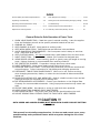
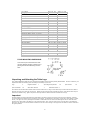
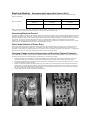
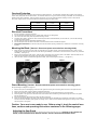
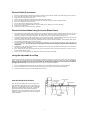
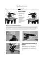
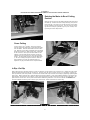
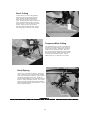
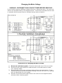
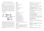
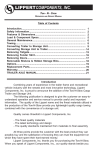
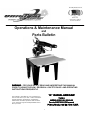
Proudly Manufactured
In the USA
American Castings
American Motors
Operations & Maintenance Manual
and
Parts Bulletin
WARNING: FOR YOUR SAFETY READ AND UNDERSTAND THIS MANUAL
PRIOR TO USING THE SAW. REVIEW ALL SAFETY RULES AND OPERATING
INSTRUCTIONS FREQUENTLY.
12”
12 RADIAL ARM SAW
This manual is provided for your convenience in
the use and care of your saw. These instructions
include operation, precautions, preventative
maintenance and other pertinent data to assist
you in assuring long life and dependable service
from your saw.
TYPE 5
MODELS 35123512-01/ 35123512-03
For s/n 20071031179 forward
1
Service Record
Serial Number_____________________
Date
Service Performed
2
Date Purchased ______________
By
INDEX
General Safety Precautions/Specifications . .
3-4
Parts Diagram and Listings . . . . . . . . . . . . . . . . .
15-23
Unpacking and Assembly. . . . . . . . . . . . . .
4-6
Setting Thermal Overload Relay/Changing Voltage
24-25
Operating Cautions/Alternative Setup . . . . .
7
Troubleshooting. . . . . . . . . . . . . . . . . . . . . . . . .
26–28
Operating Instructions. . . . . . . . . . . . . . . .
8-10
Accessories/Preventive Maintenance. . . . . . . . . . .
29
Adjustments and alignments. . . . . . . . . . . .
11-14 Warranty Information/Factory Service . . . . . . . . .
30
General Rules for Safe Operation of Power Tools
1. KNOW YOUR POWER TOOL— Read the owner’s manual carefully. Learn the applications and limitations as well as the specific potential hazards of the tool.
2. GROUND ALL TOOLS.
3. KEEP GUARDS IN PLACE. Keep guards in working order.
4. KEEP WORK AREA CLEAN. Cluttered areas and benches invite accidents.
5. AVOID DANGEROUS ENVIRONMENTS. Don’t use power tools in damp or wet locations. Keep work area well lit.
6. KEEP CHILDREN AWAY. All visitors should keep a safe distance from the work area.
7. DON’T FORCE TOOL. The tool will do a better job if used at its designed rate.
8. WEAR PROPER APPAREL. Loose clothing, gloves or jewelry may get caught in moving
parts. Rubber footwear is recommended when working outdoors.
9. USE PROTECTIVE GLASSES. If operation is dusty also wear a dust mask.
10. DON’T OVERREACH. Keep proper balance and footing at all times.
11. MAINTAIN TOOLS WITH CARE. Tools kept sharp and clean provide the best and safest performance. Follow instructions for lubricating and changing accessories.
12. DISCONNECT TOOLS FROM POWER SOURCE. When not in use, before servicing,
when changing accessories, blades, or cutters the tool should be disconnected and
locked out.
13. REMOVE ADJUSTING KEYS AND WRENCHES. Make it a habit to ensure keys and adjusting wrenches are removed prior to starting tool.
14. USE RECOMMENDED ACCESSORIES. Consult your distributor or the Original Saw
Company for recommended accessories. Using improper accessories may cause hazards.
15. SECURE YOUR WORK. Use clamps or a vise to hold work when practical.
16. NEVER LEAVE TOOL RUNNING WHILE UNATTENDED.
17. ONE OPERATOR ONLY. The person who pulls the saw should position the work.
18. DO NOT REMOVE SMALL SCRAPS FROM THE TABLE WITH YOUR FINGERS.
!!! CAUTION !!!
BOTH UPPER AND LOWER GUARDS MUST REMAIN IN PLACE FOR SAFE CUTTING
OPERATION.
This manual is not totally comprehensive. It does not and cannot cover every
possible safety and operational factor which may arise during the life of the
machine.
3
MODEL
3512-01 3512-03
MOTOR:
Horsepower
Phase
Voltage
Enclosure
RPM
Brake
Arbor
3
1
220
TEFC
3425
Automatic
1 x 2 3/16
3
3
208/230/460
TEFC
3425
Automatic
1 x 2 3/16
34 15/16
24 1/4
16"
3 1/16
1 1/4
34 15/16
24 1/4
16"
3 1/16
1 1/4
31"
39"w x 29"d
37 1/4"
15 1/2"
40"
31"
39"w x 29"d
37 1/4"
15 1/2"
40"
CAPACITIES:
Maximum
Maximum
Maximum
Maximum
Maximum
Out Rip*
C rosscut*
Miter @ 45o 1" stock*
Depth of C ut @ 90o
Depth of C ut @ 45o
GENERAL:
Table Height
Work Surface
Rear of Frame to Front of Table
Front Fence to Rear of Frame
Rear of Saw to Front of Arm
* All specifications taken with a 12" diameter blade and all guards
in place.
FLOOR MOUNTING DIMENSIONS
Your saw may be mounted to the floor.
Use the diagram at right to assist you in
placing the saw and fastening it to the
floor.
Unpacking and Attaching the Table Legs
Your Original Radial Arm Saw has been completely assembled, tested and then partially disassembled. The box included in your
shipment contains the following items necessary for assembly of your saw:
Legs
4
Magnetic Starter
3/8” Lockwasher
16
Allen Arbor Wrench
1
3/8” Flanged Cap Screws
16
1
1
Flat Arbor Wrench
3/8” Hex Nut
16
The machine can be lifted with a forklift under the steel saw frame. A sling or chain hoist may be used under the arm ONLY if
placed at the rear of the arm near the column. Attach the legs using the 3/8” hexhead cap screws, lock washers and nuts provided in the hardware bag. Tighten cap screws securely after the machine has been lowered onto its legs.
Important
All cable lengths have been adjusted during manufacture to allow for proper movement of the arm and rollerhead. However,
you should check the cables to ensure full range of movement. If adjustment is necessary, loosen the 2 cable clamps (1 inside
of arm, 1 at right rear of arm) and adjust the cables so rollerhead is free to travel the total length of the arm with the motor
pivoted in the roller head so the blade is on the right hand side. Also, check to ensure there is enough slack in the cables between the rear of the arm and the starter enclosure so the arm can be swung to the right a full 900 while the arm is elevated to
its highest position.
4
Electrical Hookup - Recommended Copper Wire Sizes (A.W.G.)
To obtain maximum efficiency from your saw motor, the feeder wire from the power source to the machine should comply
with the table below.
Motor Horsepower
1 Phase
3 Phase
3 Phase
200-240 V
200-240 V
440-480 V
3
6
6
—
3
—
4
6
NOTE: This table is based on 60-100’ distances from power supply. Less than 60’ may use one even size smaller (high number
= smaller size); 100-160’ use one even size larger, over 160’ use two even sizes larger.
Connecting Electrical Current
The motor is properly connected to the magnetic switch at the factory for operation on the electrical voltage specified on the tag
attached to the guard stud. Make sure incoming voltage from your power supply conforms to the voltage specified on the tag.
Remove the magnetic switch cover and insert power supply cable through the dust proof fitting. Connect wires to L1, L2 and L3
for 3 phase; L1 and L2 for single phase (See below left). The capped wires leading from the transformer should remain
capped. Do not attach power to the transformer. Attach the ground wire to the ground lug inside the switch enclosure. Wiring
must conform to the National Electrical Code and any applicable local codes.
Check Arbor Rotation (3 Phase Only)
Check arbor rotation with arbor nut and arbor collars removed. Open line disconnect to the saw to remove arbor nut and collars, close the line disconnect and start saw. The rotation of the arbor must be clockwise as indicated on the arrow on the
nameplate. If the rotation is counterclockwise, the incoming wires are not properly connected to the switch box. To change the
direction reverse any two of the wires leading to the switch box from the power supply.
Changing Voltage on dual voltage motors and Resetting Thermal Protection
Dual voltage motors can be operated on either of the two voltages indicated on the motor nameplate. The voltage setting from
the factory can be found on the tag attached to the guard stud. To change the voltage:
1.
2.
3.
4.
Change the motor lead connections as shown on the diagram on the inside cover of the motor conduit box. This is also
found on pages 24-25 in this manual. Disconnect and lockout the power supply before attempting voltage change.
Reconnect the transformer in the magnetic starter as shown in the diagram on the inside of the starter box cover. This is
also found on pages 25 of this manual.
Replace or adjust the thermal overload protectors (D) using dial (A), see below right) with those rated at the desired amperage range. See page 24 of this manual. Dial (B) changes the thermal reset from automatic to manual. In automatic
operation the thermals automatically reset after cooling; to proceed push the start button. If set to manual the reset button (C) will need to be pushed in to resume operation.
Contact your dealer for correct thermal overload protectors.
5
Overload Protection
Your saw is equipped with automatic reset thermal overload protection. To restart after thermals have tripped, wait until the
motor cools, then press the saw start button. If overloads continue to trip, the machine is being overloaded. Do not continue to
operate under these conditions. Find the trouble and correct it—see the electrical trouble shooting section of this manual.
The power supply branch circuit should be fused as follows using time delay fuses:
Motor Horsepower
1 Phase
3 Phase
3 Phase
200-240 V
200-240 V
440-480 V
50
30
15
3
Electrical Precautions
1.
2.
3.
4.
5.
6.
7.
Be sure machine is properly grounded.
Do not attempt to operate saw on any voltage other than the one designated.
Use correct size time delay fuses to protect incoming current.
If it takes more than 3 seconds to reach maximum speed with a standard blade, turn the saw off. ( See trouble shooting
on page 28 of this manual).
Do not cause the motor to repeatedly approach a stall.
Do not attempt to start the saw for at least 15 minutes after thermal overload has tripped.
Disconnect and lockout the saw from the power source before opening a starter box, conduit box or whenever removing
a guard.
Mounting the Blade (Caution! Disconnect power source before mounting blade)
1.
2.
3.
Place the hex box wrench over the arbor nut and place the long allen wrench in the arbor shaft end hole. Place a wood
striking block under the allen wrench to avoid marring the tabletop. Push down on the hex wrench to loosen nut (left hand
threaded). (See figure 2)
Remove the nut and first arbor collar. Wipe the arbor collar faces and mounting area on the blade. Slide the blade on the
shaft with the directional arrow away from the motor and pointing clockwise.
Place the arbor collar, recessed sides against the blade, arbor nut and tighten securely. ( See figure 1)
FIGURE 1
FIGURE 2
Guard Mounting (Caution! Disconnect/lockout power source before mounting guard)
See parts listing and diagram on page 15
1.
2.
3.
4.
5.
6.
Remove the 1/4”x 20 self tapping screw from the right front lower guard mounting hole and remove the parts secured.
Remove the right lower guard by sliding it backward and down.
Place the guard over the blade, tilting the guard to the right so the left guard clears the end of the arbor.
Seat the guard in the groove on the front of the motor arbor end bell with the guard stud through the hole in the guard.
Secure with wing nut.
Reconnect the lower right guard and replace the parts removed.
Move the carriage forward to the limit of its travel and install the anti-kickback from the bottom of the hole in the guard.
The flat on the anti-kickback goes against the locking screw. Raise the anti-kickback and tighten the locking screw. Install
the dust spout on the guard.
Caution: Your saw is now ready to use. Before using it, study the control locations, cautions and operating instructions contained in the following pages.
Adjusting the Saw Guard
The guard can be pivoted about the motor by loosening the guard mounting wing nut. CAUTION—DO NOT ADJUST THE
GUARD, OR ANTI-KICKBACK WHILE BLADE IS MOVING. KEEP ALL ADJUSTING MECHANISMS TIGHT.
6
General Safety Precautions
1.
2.
3.
4.
5.
6.
7.
8.
9.
10.
Be sure the blade rotates clockwise when facing the saw from the left side. Blade must rotate to the front of the saw.
Be sure all clamp handles are tight before turning on motor.
Keep the blade sharp and properly set.
Hold or clamp the material firmly against the guide strip when cutting.
Be sure the blade and arbor collars are clean and the recessed side of the collars are against blade.
Never oil or grease arm tracks or motor.
Do not start machine without proper tool guard.
Do not remove the anti-kickback device from the blade guard. Adjust it to just clear the work.
Keep motor air slots clean.
Return roller head to full rear after each operation.
General Cautions When Using the Lower Blade Guard:
1.
2.
3.
4.
5.
6.
7.
Used properly the lower blade guard is designed to provide protection from contact with the side of the blade. It is not
designed to prevent contact with the front or rear of the blade. When the lower guard contacts the fence or material
being cut it will rise up and expose the blade. Be careful to keep your hands out of the line of the cut.
Lower blade guards may become caught in prior kerfs in the fence or table. Alleviate this by replacing the guide fence
frequently. Always stop the saw before attempting to remove a guard that is stuck in a kerf.
Short cut-off pieces of wood may become caught between the lower guard and the blade. If this happens shut off the
saw and wait until blade stops to remove the piece.
The lower blade guard’s effectiveness is limited in bevel operations. It may have to be raised out of the way when setting the bevel angle. Be sure the power is off/locked out and blade is completely stopped before making any
adjustment.
Catching the lower guard in saw kerfs when changing the saw setup can be avoided by elevating the saw until the bottom of the guard clears the fence.
When ripping narrow strips the lower guard may have to be raised to rest on top of the guide fence. Be sure to use a
pusher stick to feed the work.
Do not use the lower guard with any accessory other than the correct size blade.
Using the Adjustable Arm Stop
The arm stop should be used whenever rollerhead travel needs to be limited, such as when repetitive cross cuts are being
made. Use of the arm stop will also prevent the blade from throwing small cut off pieces on the return stroke. Do not adjust the arm stop unless the power is off and locked out and the blade stopped. The arm stop must be used on
the right side of the arm. Proper adjustment of the arm stop is completed as follows:
1.
2.
3.
Pull the rollerhead forward far enough for the blade to sever the material and travel 1/4” past the material.
Lock the rollerhead to the arm with the riplock and place the arm stop so it is touching the rollerhead.
Loosen the riplock and return the rollerhead behind the fence.
Alternate Guide Strip Positions
Your saw was assembled with the guide strip in the
most frequently used position on the work table (see
figure 3). The guide strip may be moved to alternate
positions to accommodate varying uses. Moving the
guide strip behind the spacer board will allow for
maximum cross cutting capabilities. Moving the guide
strip back to the rear board will provide for maximum
ripping capability.
Figure 3
7
Operating Instructions
!!! CAUTION !!!
BOTH UPPER AND LOWER GUARDS MUST REMAIN IN PLACE FOR SAFE CUTTING OPERATION.
Control Locations
A.
B.
C.
D.
E.
F.
G.
H.
I.
J.
K.
L.
M.
N.
O.
P.
Rip Index Pin
Miter Latch Handle
Arm Clamp Handle
Elevating Control Handle
Miter Scale
On/Off Switch
Adjustable Arm Stop
Yoke Clamp Handle
Operating Handle
Bevel Index Pin
Bevel Scale
Bevel Clamp Handle
Anti Kickback Assembly
Serial Number Plate
Riplock
Rip Scale
Moving the Arm Horizontally and Vertically
The elevating crank is used to raise or lower the arm to accommodate cutting operations (see below left). Do not adjust the
height of the saw while the motor is running. Change the position of the arm for miter cutting is done by pulling the arm
clamp handle (A) forward and lifting the miter latch handle (B). Observing the miter scale, swing the arm either right or left
to the desired angle. The arm can quickly be located at the 0o and 45o marks by using the indexing slots machined into the
column ring. When you have located the saw at the required position engage both the miter latch and the arm clamp.
Revolving the Yoke Horizontally on
the Arm
Pull the saw carriage to the front of the arm and lock into
position with the riplock. Pull the yoke clamp handle
forward and lift the rip index pin. The yoke and motor
can now be turned either right or left for rip cuts. When
you have located the yoke motor in the required position, engage the rip index and push the yoke clamp
back.
8
!!! CAUTION !!!
BOTH UPPER AND LOWER GUARDS MUST REMAIN IN PLACE FOR SAFE CUTTING OPERATION.
Rotating the Motor to Bevel Cutting
Position
Raise the arm to allow the saw blade sufficient clearance above
the table top. Release the bevel clamp handle (A) and pull the
bevel index pin. The motor can now be moved to a bevel position as indicated on the bevel scale. Lock the motor by releasing the bevel index pin (possible only at 0o, 45o and 90o) and
by locking the bevel clamp handle.
Cross Cutting
Lock the arm in the 0o position. Place the material
securely against the guide strip– keep hands well away
from the blade. Draw the saw blade across the material. After the cut has been completed return the blade
behind the guide strip. Observe this order of operation
for all cross cuts. Never push the saw blade into the
material. Pull the blade slowly and firmly across the
material from the rear of the arm using the operating
handle. The saw blade should cut into the table about
1/ 16” when cutting through the material. Raise the
anti-kickback to just clear the material being cut.
Adjust for varying wood thickness or warped material.
In Rip—Out Rip
When ripping the arm should be locked in a cross cut position. Pull the motor to the end of the arm. Release the yoke clamp
handle by pulling forward and lift the rip index pin. Revolve motor 90o right or left for out-rip or in-rip position. Engage rip
index pin and lock yoke clamp handle. Locate saw for desired width of rip and lock saw carriage by tightening riplock against
side of arm. Rotate guard so the in-feed side almost touches the material. Lower anti-kickback assembly so the fingers are
approximately 1/8” lower than the material. Place material against the guide strip and feed evenly into the saw blade. Use
push board on narrow work. Never place hands between blade and guide fence. Do not force material and DO NOT feed
from the kickback side of the guard. Serious injury could result. Follow instructions on caution tag.
!!! DANGER !!!
NEVER FEED MATERIAL FROM THE KICKBACK SIDE OF THE GUARD. SERIOUS INJURY COULD RESULT.
RESULT
9
Bevel Cutting
Lock the arm in the cross cutting position.
Raise the motor by rotating the elevation
crank. Release the bevel clamp and the
bevel index pin and tilt the motor in the
yoke. The bevel angle is shown on the bevel
scale. Release the bevel index pin and lock
the bevel clamp. Lower the arm into cutting
position. Adjust the arm stop to assure
clearance between blade and base. Pull the
saw through as you would for cross cutting.
Compound Miter Cutting
The compound miter is merely a combination of
the bevel cut and the miter cut. Set up the machine for bevel cutting. Release the arm clamp
handle and the miter latch handle. Move the
arm into the required position and lock the miter
latch and arm clamp. Adjust arm stop to assure
clearance between blade and base. Pull the
blade through as you would for cross cutting.
Bevel Ripping
Lock the arm in the cross cut position. Elevate the
motor. Rotate the yoke to the rip position and the
motor to the desired bevel position. Lock all latches
and clamps and tighten the rip lock. Adjust the
guard and anti-kickback as you would for the ripping
position. Always readjust as required. Use a push
board to feed the material into the blade; DO NOT
place hands between blade and guide fence. Do not
feed the material rapidly.
!!! DANGER !!!
NEVER FEED MATERIAL FROM THE KICKBACK SIDE OF THE GUARD. SERIOUS INJURY COULD RESULT.
RESULT
10
Maintenance Adjustments and Alignments
Caution! Disconnect and lockout power supply before making any adjustments or alignments.
Your saw has been completely assembled, aligned and tested at the factory...then partially disassembled for shipment. Handling during shipment may cause some misalignment and the following information will enable you to correct any cutting
inaccuracy you discover. These adjustments may also be necessary after a period of use. (See preventive maintenance)
Important ...Since one adjustment may affect another it is important to run through the adjustments in the sequence as
follows.
Adjustment of Base to Column Fit
If excessive side motion exists at the end of the arm
while the arm clamp is engaged, adjustment to the
base or bronze gib (C) is generally necessary. To adjust:
1.
2.
3.
Loosen all pinch bolts (A) and set screws (B). Pull
the arm clamp handle forward.
With the motor and yoke in the rearmost position
the elevation effort should be easy. Tighten the
bottom pinch bolt until there is an increase in the
elevation effort. Once elevation becomes snug
back off the bolt 1/4-1/2 turn. Repeat this for the
other two pinch bolts.
Tighten the gib set screws (B) hard, then back
them off. Run them back up against the gib
lightly, then snug up the locknut.
Adjustment of the Arm Clamp
The arm clamp holds the arm tightly on the column
in the desired position for cutting. The arm clamp
handle should be upright when tightened. If it goes
beyond center adjust as follows:
1.
2.
3.
4.
Place motor carriage in the rearmost position.
Loosen the arm clamp set screw (A).
Move arm clamp handle to upright position and
tighten the arm clamp handle bolt (B). Note
this is a left hand threaded bolt.
Tighten the screw.
Adjustment of the Rollerhead to Arm
Accurate work cannot be done if the roller bearings in the motor carriage are not in proper adjustment. When play develops
between the rollerhead and the arm the following adjustment is required:
1.
2.
3.
4.
5.
Bring the rollerhead to the front of the arm and lock in place using the adjustable stop. Move saw to in-rip position.
Loosen the sockethead screws holding the arm end cap and rotate the end cap upward to expose bearings.
Clean the tracks thoroughly. Wipe them clean with a solvent, do not use kerosene. Use extreme caution as most solvents are toxic and/or flammable. Do not grease or oil the tracks.
Loosen the locking set screws (A) two full turns to release the eccentric shafts. (Both are located on the right hand side)
Loosen the hex jam nuts (B) on both bearing pins.
Continued on the next page
11
Adjustment of the Rollerhead to Arm (cont’d)
5.
Insert socket wrench into bottom of bearing shaft (C) and
turn until the bearing touches the arm track on both top
and bottom radii. Repeat for both shafts. Bearings should
be tightened only so that they roll and do not slide.
Replace the end cap and return saw to normal position.
6.
Note-Too much pressure on the roller bearings will cause
excessive and unnecessary wear in the parts and make
the carriage work harder. Seven to ten pounds average
pull on the carriage is a desirable preload.
Adjustment of the Yoke Clamp Handle
The yoke clamp handle (A) provides a friction lock between
the yoke and the rollerhead. When in operating position it
should be approximately 90o to the handle of the yoke. If
it is not, adjustment should be made as follows:
1.
2.
3.
4.
5.
Pull yoke clamp handle (A) forward.
Remove socket head cap screw (B) locking the star
washer on the underside of the yoke.
Using the same allen wrench, rotate the kingbolt (C)
counterclockwise to tighten.
Replace the cap screw.
Check to ensure handle will lock the yoke to the rollerhead
Adjustment of Table Top Parallel to Arm
The arm tracks must be parallel to the tabletop at all
points. This assures uniform depth of cut, especially
when dado cutting. Remove the blade and insert an
arbor wrench or allen wrench between the saw arbor
collars. Lower the wrench until it touches the tabletop.
If the top is not level:
1.
2.
3.
4.
Locate the highest point by swinging the arm from
side to side and moving the carriage back and forth
on the arm.
Loosen the lock nuts beneath the table frame.
Raise the jack screws so as to bring the low parts of
the tabletop level with the high spots.
Tighten the lock nuts beneath the table frame.
How to check the Guide Strip For Accuracy
For accurate work the guide strip must be straight. If the machine has been exposed to the weather or used for a period of
time the wood parts may become warped or worn so that the guide strip is no longer straight. It should be made straight by
planing and sanding or replacing. Check it with a straight edge or square before proceeding and make any adjustments necessary.
Caution! Disconnect and lockout power supply before making any adjustments or alignments.
12
To Square Saw Blade with the Table Top
Pull the saw to middle of table and lock into place.
Make sure the tabletop is level and place a steel square
against the side of the blade; the square should be
against the gullets and not the teeth of the blade. If
the blade is not square to the tabletop:
1.
2.
Remove two screws holding the bevel pointer.
Loosen the two sockethead cap screws (A) located
on the outside of the dial plate.
Release the bevel clamp handle (B).
Rotate the motor so the saw blade is flat against
the square. Tighten the two locking sockethead
cap screws.
Replace the bevel pointer.
Engage the bevel clamp and recheck for square.
Adjust the bevel pointer washer/logo plate to line
up with zero on the bevel scale.
3.
4.
5.
6.
7.
Adjustment of Bevel Clamp Handle
The bevel clamp holds the motor tightly at any angle by
clamping the yoke around the dial plate. If adjustment becomes necessary do the following:
1.
2.
3.
Release the bevel clamp handle by pulling it away from
the dial plate as shown.
Use an allen wrench to holdi the cap screw stationary
and adjust the jam nut as necessary.
Engage the bevel clamp.
Adjusting Crosscut Travel Parallel to Arm Tracks
The leading and trailing teeth of the saw blade should travel in the same plane parallel to the arm tracks. When the saw blade
is not parallel to the arm the result will be what is called “heel” - the back of the blade will not follow in the kerf of the front of
the blade. Signs of a blade heeling are indicated when the rear teeth of the blade mark the material with an offset in the cut.
This may be checked by cutting a piece of material at least 1”x4” . Place the material against the guide fence and crosscut a
narrow strip; do not pull the saw blade entirely through the material but just allow the front teeth to clear the material. Stop
the cut with the rear teeth remaining in the cut. Stop the saw and pull the material away from the blade prior to returning the
blade behind the guide fence. Adjustment is necessary if rear teeth marks are prominent on either side of the cut ( the rear
teeth will arc toward the guide fence). This can also be checked by placing a square across the blade as shown; be sure to
avoid placing any part of the square on the teeth. The square should be in contact with the blade in both the front and rear. To
correct this situation:
A.
If marks are made on the right hand side of material:
1.
Release the bevel clamp handle.
2.
Loosen the right and left lock nuts on the rear yoke
trunion bushing.
3.
Unscrew the left set screw about 1/6th turn and screw
in the right screw the same amount.
4.
Tighten the lock nuts, engage the bevel clamp handle
and recheck.
B.
If marks are made on the left hand side of material:
1.
Release the bevel clamp handle.
2.
Loosen the right and left lock nuts on the rear yoke
trunion bushing.
3.
Unscrew the right set screw about 1/6th turn and
screw in the left screw the same amount.
4.
Tighten the lock nuts, engage the bevel clamp handle
and recheck.
Continued next page...
13
Adjusting Crosscut Travel Parallel to Arm Tracks (continued)
After making the left and right adjustments, tilt the motor to a 45o bevel cutting position and make cuts in a 2”x 4” piece of
material. If tooth marks appear the motor is too high or low in the rear yoke:
A.
If marks are made on the bottom side of material:
1.
Release the bevel clamp handle.
2.
Loosen the right and bottom lock nuts on the
rear yoke trunion bushing.
3.
Unscrew the left set screw about 1/6th turn and
screw in the same amount the set screw located
on the bottom of the yoke trunion.
4.
Tighten the lock nuts, engage the bevel clamp
handle and recheck.
B.
If marks are made on the upper side of material:
1.
Release the bevel clamp handle.
2.
Loosen the right and left lock nuts on the rear
yoke trunion bushing.
3.
Unscrew the bottom set screw about 1/6th turn
and screw in the left screw the same amount.
4.
Tighten the lock nuts, engage the bevel clamp
handle and recheck.
If after making these adjustments the blade continues to heel, particularly if the blade heels on both sides of the material, the
blade may require tensioning. If the blade must be re-tensioned contact your local distributor.
Square the Saw Travel with the Guide Strip
Place a square against the guide strip and along the path of the blade. Pull the saw carriage as though making a crosscut
and observe the position of the blade in relationship to the square. If the crosscut line is not square adjust as follows:
1.
2.
3.
4.
5.
6.
7.
Loosen the arm clamp handle (A).
Loosen set screws (B).
Move saw carriage along square to determine necessary adjustment.
If the blade moves toward the square as it comes forward; disengage the miter latch (C), unscrew the rear adjusting
screw (D) 1/8 of a turn and screw in the front adjusting screw (D)1/8 turn. If blade moves away from square go to
instruction #6.
Engage miter latch and recheck. If saw travel is now square, tighten set screws and engage arm clamp.
If the blade moves away from the square as it comes forward: disengage miter latch (C), loosen the front adjusting
screw (D) and tighten the rear adjusting screw (D). Engage the miter latch, recheck and repeat as needed.
After saw travel has been properly aligned tighten the set screws (B) to lock adjusting screws in place.
Caution! Disconnect and lockout power supply before making any adjustments or alignments.
14
Parts List and Ordering Instructions
Order only genuine replacement parts from your Original Saw Company Dealer.
When ordering parts be sure to include:
Name of manufacturer—Original Saw Company
•
•
•
•
•
Complete machine identification data found on name plate on front of frame
Complete motor identification from motor name plate
Quantity, part number and description of parts required
Complete shipping and billing instructions
Because of the importance of tightening critical bolts and set screws to an established torque, each of the following parts lists pages contains torque tightening requirements for certain fasteners. These fasteners have
their part numbers highlighted and torque requirements specified.
Information is supplied on these parts lists showing where lubrication is desired. Such areas are marked and
a general purpose grease should be used.
Guard Assembly
Assembly Part No. 400700-02
Index
No.
1
2
3
4
5
6
Part
No.
400710-01
123451-01
003041
103805
080666
400740
Description
Qty
Upper Guard
warning label
Drive Screw
Warning Plate
Thumb Screw
Anti-kickback assy
1
1
2
1
1
1
Index Part
No.
No.
7
400730
8
052511
9
400720
10
082007
Parts not shows
096803
15
Description
Qty
Guard Ring
1/4-20 x 3/4 screw
Guard Retainer
Wing nut
2
4
4
1
Bushing
4
Arm Assembly
400100
Index
No.
1
2
3
4
5
6
7
8
9
10
11
12
14
Part
No.
083294
096767
083122
003041
123513
003041
103117
082200
400110
123514
080634
081778
400140
Description
Qty
Arm Clamp Handle
Miter Latch
Miter Latch Adjusting Screw
#4x 5/16 Drive Screw
Trademark Tag
#4x 5/16 Drive Screw
Caution Plate
5/16-18x3/8 Sockethead Screw
Arm
Caution Label
1/4 20x 1/2 Roundhead Screw
Cable Clamp
Rip Scale
1
1
2
2
2
4
1
1
1
1
1
2
1
Index
No.
15
16
17
18
19
21
22
23
24
25
26
27
16
Part
No.
080489
203597-09
096771-01
082387
400130
082387
103522
070869
400120-01
084173
080589
900101-02
Description
8-32x3/8 Panhead Screw
Miter Pointer
Arm Clamp Bolt
1/4-20x1/4 Cuppoint Set Screw
Spring Return
1/4-20x1/4 Cuppoint Set Screw
Set Screw Slug
Bumper
End Cap
1/4” Spring Lockwasher
1/4-20x1 1/2 Sockethead Cap Screw
Switch Kit
Qty
1
1
1
1
1
2
2
1
1
2
2
1
Rollerhead Assembly
800500-02
Index
No.
1
2
3
4
5
6
7
Part
No.
400221
400220
400225
069532
082387
400210
000415
Description
Eccentric Shaft
Bearing
King Bolt
Knob
1/4-20 x 1/4 Cuppoint Set Screw
Rollerhead
3/8 Split Lockwasher
Qty
Index
No.
2
4
1
1
1
1
4
8
9
10
11
12
13
14
17
Part
No.
099369-07
088165
119510
082387
400230
096776
400222
Description
3/8-24 Hex Finish Nut
Index Pin Spring
Index Pin
1/4-20 x 1/4 Cuppoint Set Screw
Riplock
Knob
Concentric Shaft
Qty
4
1
1
1
1
1
2
Yoke Assembly
400300
Index
No.
1
2
3
4
5
6
7
8
9
10
11
12
13
14
15
Part
No.
119510
088165
400336
099376-04
082413
400335
099376-04
082413
082413
099376-04
400320-01
099384-07
082166
400337
082181
Description
Locating Pin
Latch Spring
Support Screw
10-24 Hex Jam Nut
10-24x 1 1/4 Cup Pt Set Screw
Bushing
10-24 Hex Jam Nut
10-24x 1 1/4 Cup Pt Set Screw
10-24x 1 1/4 Cup Pt Set Screw
10-24 Hex Jam Nut
Dial Plate
5/16 Lockwasher
5/16-18x 1/2 Sockethead Cap Screw
Front Support Screw
5/16-18x 2 3/4 Sockethead Cap Screw
Qty
1
2
1
1
1
1
1
1
1
1
1
2
2
1
1
Index
No.
16
17
18
19
20
21
22
23
24
25
26
27
28
29
18
Part
No.
099361-16
400330
400323
400322
080489
099262-04
069532
099358-08
099364-04
082200
400310
400340-01
400341
400342
Description
5/16 Flat Washer
Bevel Clamp Handle
Bevel Scale
Bevel Pointer
8-23x 3/8 Self Tap Screw
8-32x 1/4 Panhead Screw
Knob
5/16 Flat Washer
5/16-18 Hex Jam Nut
5/16-18x 3/8 Sockethead Cap Screw
Yoke
Yoke Clamp Handle Washer
Yoke Clamp Handle
Handle Grip
Qty
2
1
1
1
2
1
1
1
1
1
1
1
1
1
Base and Column Assembly
400400
Index
No.
1
2
3
4
5
6
7
8
9
10
11
12
Part
No.
400440
400470-01
121616
099191-36
099374-05
082398
099186-24
084180
099365-05
400450
400460
400420
Description
Column
Elevating Assembly
Gib
3/8-24x 2 1/4 Hex Tap Bolt
1/4-20 Hex Jam Nut
1/4-20x 1 Cup Pt Set Screw
3/8-16x 1 1/2 Hedhead Cap Screw
3/8-16 Heavy Hex Nut
3/8-24 Jam Nut
Miter Scale
Oil Free Bearing- Lower
Thrust Cap
Qty
1
1
1
3
2
2
4
4
3
1
1
1
Index
No.
13
14
15
16
17
18
19
20
21
22
23
24
19
Part
No.
099384-07
099155-24
400460
096714
096785
400410-01
082024
082023
080589
400441
080594-01
082098
Description
5/16 Lockwasher
5/16-18x 1 1/2 Sockethead Cap Screw
Oil Free Bearing
1/4-20x 5/16 Cup Pt Set Screw
Elevating Crank Assembly
Base
1/4 Elastic Stop Nut
1/4-20x 2 Hexhead Bolt
1/4-20x 3/4 Sockethead Cap Screw
Column Key
Elevating Plug
3/8-16x 1/2 Hexhead Cap Screw
Qty
2
2
1
2
1
1
1
1
4
1
1
1
Magnetic Starter Assembly
(Telemecanique Starter)
3
4
Index
No.
1
2
3
4
5
6
7
8
9
10
11
12
13
Description
Transformer
208/230/460 volt
380/575 volt
Enclosure
Magnetic Starter
Heater Pack
208v 1 phase
230v 1 phase
208v 3 phase
230v 3 phase
460v 3 phase
Nylon nut 3/4
Nylon nut 1/2
Liquid tight fitting 3/4
Motor cable
Liquid tight fitting 1/2
Control cable
Fuse holder
Fuse
Warning Label
Qty
3 HP 3 Phase
3 HP 1 Phase
122105-50
122105-51
096759-03
122108-84
122105-50
n/a
096759-04
122108-84
—
—
122110-83
122110-83
122110-83
068820-02
068820-03
081724-01
21703164
066425-01
21703338
068723
081554
123540
122110-86
122110-86
—
—
—
068820-02
068820-03
081724-01
21703114
066425-01
21703338
068723
081554
123540
1
1
1
1
1
1
1
9ft
1
9ft
1
1
1
20
Table & Frame Assembly
400500
Index
No.
1
2
3
4
5
6
7
8
9
10
Part
No.
400531
400532
400533
400519
400535-01
099370-04
099384-07
099358-08
096779-01
096778-01
Description
Front Board
Spacer Board
Fence Board
Rear Table Cleat
Rear Board
5/16 Hex Nut
5/16 Lock washer
5/16 Flat Washer
5/16-18 x 1 1/4 Carriage Bolt
5/16-18 x 2 1/2 Carriage Bolt
Qty
Index
No.
1
1
1
1
1
33
24
9
6
6
11
12
13
14
15
16
17
18
19
20
21
21
Part
No.
088181-01
000415
084180
400510
012122
123459-01
096723
400520
099155-44
068666-01
068706
Description
Frame Leg
3/8 Lockwasher
3/8-16Heavy Hex Nut
Frame
# 4 Drive Screw
Frame Tag
3/8-16 x 1 Hexhead Flanged Bolt
Table Cleat
5/16-18 x 3 Set Screw
Table Clamp
Clamping Knob
Qty
4
16
16
1
4
1
16
3
3
2
2
Motor Assembly
Index
No.
1
2
3
4
5
6
7
10
11
12
13
14
15
16
17
18
19
20
21
22
23
24
25
26
27
28
29
Part
No.
21703164
21703114
081721
099248-12
123466-01
123466-08
000407
088175-06
000418
000417
096994
400608-56
400609-95
000418
072222
123420
099248-28
541003
123402
081953
123417
539160
539161
539162
037846
541007
081932
123414
026587
123408-07
083419
123413
Description
14-4 motor cable 3512-03
14-3 motor cable 3512-01
90 degree strain relief
8-32 x 3/4 pan hd mach screw
motor data plate 3 phase
motor data plate 1 phase
#8-32 hex nut
Relay Box
#8 lock washer
#10 lock washer
10-24 x 3/4 pan hd screw
220 volt 1 phase stator (3512-01)
208/230/460 volt 3 phase 50/60hz
#8 lock washer
Brake module
spacer (brake module)
#8-32 x 1 3/4 pan hd mach screw
Fan End Bell
Brake Disk
#10-24 hex nut
fan assembly
shim washer (.002)
shim washer (.005)
shim washer (.010)
retaining ring
Fan housing
#10-24 hex cap nut
Ball Bearing
Woodruff Key
Rotor and Shaft
Bearing Cap
Ball Bering
Qty
Index
No.
9.75
9.75
1
4
1
31
32
33
34
35
36
37
38
39
40
2
1
2
6
2
1
4
1
2
2
1
1
4
1
AR
AR
AR
1
1
4
1
1
1
1
1
43
44
45
46
47
48
49
50
51
52
53
54
55
56
57
58
59
60
22
Part
No.
541351
096713
088146
070786-01
099263-20
123419
096626
123418
123406
081733
081730
101820-01
081433
301020-02
203511
121319
121318
123460
123403
123404
121341
66045-04
068595-01
099249-05
099361-10
000417
068873
083382-01
123484
123485
099248-06
Description
Retaining Ring
Guard Stud
Arbor End Bell
Cover Plate
#10-24 x 1 1/4 pan hd mach screw
Tie Rod
Box Cover
Spring (brake)
Brake Coil Assembly
Wire Connector 208/230/460 volt
Wire Connector 575
Arbor Collar (ground)
Arbor Nut
Arbor Wrench Flat
Arbor Wrench Allen
Connection Diagram 208/230/460 v
Connection Diagram 575 v
Connection Diagram 220 v 1 phase
Fan Baffle
Coil Housing
Bumper (peel & stick)
insulating strip (brake module)
Relay
#10-24 x 3/8 pan hd mach screw
#10 flat washer
#10 lock washer
Capacitor Clamp
Capacitor
Lead Wire Assembly
Lead Wire Assembly
#8-32 x 3/8 pan hd mach screw
Qty
1
1
1
1
4
4
1
4
1
*
*
2
1
1
1
1
1
1
3
1
1
1
1
1
1
1
1
1
2
Changing the Motor Voltage
WARNING—DISCONNECT AND LOCKOUT POWER BEFORE SERVICING
If your machine requires a different voltage, follow the instructions below. The motor will
need to be rewired according to the diagrams below. The thermal overloads must be reset
or replaced with the proper pieces to maintain thermal motor protection.
Instructions for Changing the Motor Voltage
1)
2)
3)
4)
Disconnect and lockout power– Electrical shock could occur if this is not done.
Reconnect motor and transformer leads as shown in the chart above to match
your required voltage.
Reset the dial for the proper amperage setting shown in the chart above. If your
overload block does not have the proper settings, the block will have to be replaced
with one appropriate for your voltage.
Recheck all connections and replace lids on the motor box and magnetic starter
enclosure before restoring power.
23
Alignment Guide for Accurate Cutting
The following guide is provided for your convenience. A saw that is not properly adjusted will not
yield the desired accuracy and quality of cut. It should be noted any adjustment made will effect
another, therefore it is best to perform all of the adjustments when correcting any one problem.
PROBLEM
Saw will not make a square cross cut
or a good 45o miter cut
POSSIBLE CAUSE
−
−
−
−
−
−
−
−
−
Lumber has a tendency to walk away
from fence when ripping or ploughing
−
−
−
Saw stalls when ripping or ploughing
−
−
−
−
−
−
−
−
Saw blade scores lumber, finish cut
is not smooth
−
−
−
−
−
−
−
−
Arm is not perpendicular to
guide fence
Arm has excessive play at end
SOLUTION
−
−
−
Too much play between arm and −
Column is loose in base
column
Rollerhead loose in arm (left to
right play)
Yoke loose when clamped to
rollerhead
Sawdust between lumber and
guide fence
Table not parallel with arm
Guide fence not straight/rear
edge of fixed board not straight
Saw blade is not parallel with
fence
Arm not perpendicular to guide
fence
Dull blade or cutters
Adjust cross cut travel with
guide fence (p. 14)
Tighten adjusting screws
Make proper adjustment (p. 11)
Make proper adjustment (p. 11)
−
Adjust rollerhead (p. 11)
−
Adjust yoke clamp handle (p.
12)
−
Clean tabletop
−
−
Make proper adjustment (p. 12)
−
−
Make heel adjustment (p. 13)
−
Sharpen or replace blade
−
−
Wrong blade
−
Column too loose in base
−
Too much play between arm and −
Replace fence/sand or replace
(p. 12)
Adjust crosscut travel with guide
fence (p. 14)
Fence not straight
Replace fence
Feed rate too fast
Slow feed rate
column
Rollerhead loose in arm
Yoke loose when clamped to
rollerhead
Sawdust between lumber and
fence
Use correct blade
Make proper adjustment (p. 11)
Make proper adjustment (p. 11)
−
−
Make proper adjustment (p. 11)
−
Clean tabletop
−
−
Too much play between arm and −
Make proper adjustment (p. 12)
Saw blade is heeling
Make heel adjustment (p. 13)
Column too loose in base
Make proper adjustment (p. 11)
column
Rollerhead loose in arm
Make proper adjustment (p. 11)
−
−
Make proper adjustment (p. 11)
−
−
Replace blade
Not feeding saw properly
Using improper blade
−
Yoke too loose when clamped to
rollerhead
Bent or dull blade
24
Make proper adjustment p. 12)
Draw blade across lumber with
slow steady pull
Change blade.
PROBLEM
Saw blade or dado blades tend to
push lumber to one side when cross
cutting
POSSIBLE CAUSE
−
−
−
−
−
−
−
Cut depth varies from one end of
stock to the other
450 bevel cut not accurate
Column too loose in base
Too much play between arm
and column
Rollerhead too loose in arm
Yoke too loose when clamped to
rollerhead
Fence not straight
Dull blade or cutters
−
−
−
Tabletop not parallel with arm
−
Saw blade not perpendicular to
tabletop
Column too loose in base
−
−
−
−
−
−
Saw tends to advance over lumber
too fast
Saw blade is heeling
−
−
−
Column too loose in base
Too much play between arm
and column
Too much play between arm
and column
Rollerhead too loose in arm
Yoke too loose when clamped to
rollerhead
Bevel clamp handle loose
Tabletop not parallel to arm
Rollerhead bearings out of adjustment
Dull blade
Not feeding saw properly
SOLUTION
−
−
−
Make heel adjustment (p. 13)
−
−
Make proper adjustment (p. 11)
−
−
Replace fence
−
−
−
Adjust tabletop to arm (p. 12)
−
Make proper adjustment (p. 13)
−
−
Make proper adjustment (p. 11)
−
−
Make proper adjustment (p. 11)
−
−
Make proper adjustment (p. 13)
−
Adjust bearings (p. 11)
−
−
Replace or sharpen blade
−
−
Clean tracks
Make proper adjustment (p. 11)
Make proper adjustment (p.11)
Make proper adjustment (p. 12)
Replace or sharpen
Make proper adjustment (p. 11)
Make proper adjustment (p. 11)
Make proper adjustment (p. 11)
Make proper adjustment (p. 12)
Make proper adjustment (p. 12)
Draw blade across lumber with
a slow steady pull
Saw does not move smoothly in arm
tracks
−
−
Dirty tracks
Miter scale not accurate at various
miter angles
−
Scale pointer not properly adjusted
−
Adjust scale pointer
Elevating handle slips when elevating or lowering the saw
−
Base not adjusted properly
−
Adjust base to column (p. 11)
Clamping force not sufficient at miter angles other than 450
−
Arm clamp out of adjustment
−
Adjust arm clamp (p. 11)
Clamping force not sufficient at
bevel angles other than 450
−
Bevel clamp handle too loose
−
Adjust bevel clamp (p. 13)
Bad bearing
25
Replace bearing
ELECTRICAL TROUBLE-SHOOTING GUIDE
CAUTION—HIGH VOLTAGES ARE DANGEROUS—BE SURE POWER IS OFF AND LOCKED
OUT WHEN INSPECTING OR REPAIRING MOTOR OR CONTROLS
TROUBLE
POSSIBLE
CAUSE
SUGGESTED REMEDY
Power line not connected to
cable.
Correct power wiring. See wiring diagram inside magnetic starter box.
Thermal overload relays may
have tripped.
Allow time for overload relays to cool.
Saw motor
will neither
start nor
Faulty (brown) line fuse, line
circuit breaker tripped.
Check for presence of proper voltage at motor.
hum
Defective control transformer.
Start and stop switches at end
of arm may be defective.
Check circuit with continuity meter. Ensure power is off.
Faulty starter.
Open circuit in a thermal relay
heater.
Remove heaters. If defective, heater may be completely
burned up. Install new heater if required.
Open circuit in motor cable or
cable lugs.
Use a continuity meter and check each wire between
control unit and motor. Check lug connections.
Wiring error.
Check connections in starter box and conduit box, refer
to motor and starter connection diagrams.
Mechanical binding—shaft
should turn freely by hand.
Tap end of shaft with mallet to seat bearings in end bells.
Check bearings and bell etc. Replace as needed.
Low voltage-voltage should be
measured at the motor while it
is starting and blade attached.
Voltage should not drop lower
than 185 volts for 208, 220
and 230 volt systems.
Check for loose or high resistance connections– make
sure lines are of ample capacity and other equipment is
not pulling down the voltage.
Burned out stator
If motor smells or has been smoking each phase winding
should be checked with a test lamp or continuity meter.
Bad capacitor (single phase
only).
Turn off power, remove motor nameplate. Discharge
capacitor by short circuiting terminals; remove motor
from circuit. Test with ohm meter. Needle should jump
when leads are touched to capacitor terminals and fall
back to a high resistance as capacitor charges.
Bad starting relay (single
phase only).
If contacts are excessively burned, pitted or welded together the relay must be replaced. Check for open relay
coil using continuity meter.
Wrong heater or fuse.
Replace with proper heater, fuse or circuit breaker.
overload
Excessive currents.
Check for grounds or shorts.
relay or
Low voltage.
Check voltage while starting as outlined above.
Saw motor
hums but will
not start (Shut
off power
immediately)
Motor trips
blows line fuse. Loose or faulty connection.
Locate and repair.
26
ACCESSORIES
Auto Return Device—Returns carriage to start position or rear of arm (required by OSHA). Standard
equipment on 1994 and newer saws.
400130
For all Black & Decker DeWalt Contractor models and all Original 3512 Series
Roller Table Extension— 20” wide and 8’ long. Mounting brackets and support legs included.
40030-03
Roller table extension 12” centers (8 Rollers)
40030-04
Roller table extension 6” centers (15 Rollers)
Blades—
T2008
12” x 48 tooth x 1” arbor (Carbide)*
T2008-01
12” x 60 tooth x 1” arbor (Carbide)*
T2008-03
12” x 100 tooth x 1” arbor (Carbide)*
T2008-04
12” x 100 tooth x 1” arbor (ATB High Rake)*
T2008-09
13” x 72 tooth x 5/8” arbor (Carbide)
* Blades are 1” arbor can be used with a bushing to fit 5/8”
PREVENTIVE MAINTENANCE
Original Radial Arm Saws are designed to provide you with precision cutting with a minimal amount of maintenance. The frequency of the maintenance depends on the amount of use and the desired cutting quality.
Always disconnect and lockout power supply before performing maintenance.
After every 10 –20 hours of use the column should be wiped down with a clean dry rag. Wipe the tracks of
the arm with a clean rag and either denatured alcohol or paint thinner. Move the carriage back and forth several times and clean it again. DO NOT lubricate the arm tracks; doing so may cause excessive arm wear due
to dust attracting to the arm tracks. Keep the tracks clean and dry; periodically wipe or vacuum sawdust from
all exposed surfaces. Check for loose or broken parts and replace if necessary with genuine Original Saw
Parts. Check the blade to see if it is sharp and free of wobble.
Adjustment and alignment of saw is necessary only when cutting results in unacceptable accuracy.
After many years of use your saw may need replacement parts. If any of the following wears out all others
listed should be checked also.
Rollerhead bearings: Check for free, smooth rotation. Do not attempt to lubricate.
Arm Tracks: If the saw is used primarily for short cut-offs, the tracks may wear making it difficult to adjust
the rollerhead bearing for full length arm travel. Arms can generally be remachined—contact Original Saw for
pricing and shipping instructions.
Motor bearings: Check for free, smooth rotation. Do not attempt to lubricate.
Elevating mechanism: Remove, clean and lubricate with type EP grease. Check for wear between nut and
jack screw. Replace assembly if loose.
27
Industrial Use Warranty Information
Your new Original Radial Arm Saw is precision manufactured under strict quality standards. In the unlikely event there is trouble with your machine, the Original Saw Company warrants the machine for the period of one year from the date of purchase. The
warranty covers defects in materials and workmanship. We will cover the cost of the
defective part and ground shipping. If a replacement part is sent under warranty the
defective part must be returned to Original Saw Company or you will be charged for the
replacement. The part must also be accompanied by a return goods authorization number. This number can be obtained by calling customer service at 1-800-733-4063.
When the part is returned it may be repaired or replaced at our discretion. The part
must be shipped prepaid to: The Original Saw Company, Attn. Warranty Replacement
Counter, 465 Third Avenue SE, Britt, Iowa 50423.
IMPORTANT
IMPORTANT
IMPORTANT
To assure product reliability, repairs, maintenance and adjustments should be performed by Authorized Service Centers, always using genuine replacement parts.
465 3rd Avenue SE
Britt, Iowa 50423
Phone 641-843-3868 or 800-733-4063
Fax 641-843-3869
For parts or service please contact the manufacturer for the dealer nearest you.
Printed in the USA © The Original Saw Company 04/2005—(revised 4.16.2007, 10.30.2007 (new starter))
28