1
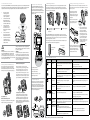
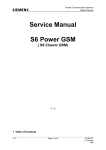
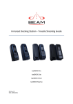
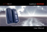
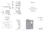
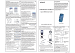
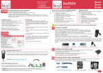
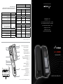
Suitable for the IsatPhone Pro
Quick Start Guide
IsatDock MARINE
1. IsatDock MARINE Equipment Overview
14
1
Back Panel Connectors
15.
Status Indication LED
14.
Function Buttons
13.
IsatPhone Pro (not included)
12.
IsatPhone Pro Eject Button
11.
Key lock
10.
Cover Seal
9.
Speaker Phone Button
8.
Microphone
7.
Speaker (under handset)
6.
Privacy Handset
5.
Mounting Cup
(spring or desk/wall cup options)
4.
Marine Cover
3.
Cover Lock Clasp
2.
IsatDock MARINE Unit
1.
2
a
b
c
d
e
3
9
10
11
4
12
5
6
a. USB Data Interface
13
b. Alert loop connection
8
d. DC power and accessory input
7
c. RJ11/POTS interface
14
2. Specification Summary
Average Power
Consumption
Current @ 12V
Average
Transmit + Charging
Victoria, 3170, AUSTRALIA
360mA
Standby + Charging
8 Anzed Court, Mulgrave
130mA
Power w/o IsatPhone
Pro
BEAM Communications Pty Ltd
Web: www.beamcommunications.com
5mA
Sleep Mode
Physical Specifications
Information: [email protected]
Tel: +61 3 8588 4500
Watts
1.6W
4.3W
875mA
3.5 A
Peak Current
Dimensions
Support: [email protected]
Fax: +61 3 9560 9055
10.5W
60mW
Accuracy
3.67lbs
1665g
Weight - dock
10.6 x 7.4 x 4
(inches)
270 x 189 x 101
(mm)
5.99lbs
-31oF to +185oF
-35oC to +85oC
Storage
-30oC to +70oC
Operating Range
-22oF to +158oF
Humidity
<= 75% RH
GPS Module (internal)
1Hz
Update Rate
14 tracking, 51 channel acquiring
Channels
Position 2.5m CEP, Velocity 0.1m/s,
Timing 300ns
Altitude 18000m, Velocity 515m/s
Operational Limits
-161 dBm
Sensitivity
Cold 30sec, Hot 1sec
Acquisition TTFF
Connectors / Interfaces
POTS/RJ11
42W
2715g
Total Kit Weight
Environment Specifications
+32oF to 113oF
0oC to +45oC
Battery Carging Temp*
www.beamcommunications.com
PART #: USRQSG006201
Inmarsat Antenna
GPS Antenna
10-32V DC
RJ11/2-wire, 5REN @ 600m
Adjustable dial, ring, busy tone
configured frequency and adaptive
impedance.
TNC-Female
SMA-Female
4-way microFit
(AC/DC adaptor, or DC lead)
In-built speaker/microphone
Speaker phone
Micro USB
Configuration/Data
RJ9 connector
Privacy Handset Port
* It is ideal for the ambient temperature to be approximately 18
degrees below the 45oC upper limit for the handset to charge
the battery whilst docked.
3. Inmarsat Antenna Connection
5. Access to rear connector bay
6. Mounting Orientation
7. Docking and Un-docking your IsatPhone Pro
To connect the IsatDock MARINE to the GSPS inmarsat Antennas, requires the use of certified satellite and GPS
antenna cables to be used. These cables are purpose built cables as approved by Beam to manage the power
requirements for the antennasystem. Approved cables can be found at www.isatdock.com/marine.
For the IsatDock MARINE, the external cable
interfaces are at the rear of the docking station.
The cover panel creates the IP rating for the
electrical interface and retains the cables in their
respective channels. The cover panel is fixed in
place by 7 screws.
There are four keyhole shaped slots in the mounting bracket that mate with
feet on the rear of the plastics. To attach the bracket, the larger end of the
keyhole will pass over the feet. The bracket is then slid up to lock the feet into
the narrow section of the keyhole.
To place the IsatPro Phone into the docking unit, both the ‘covers’
on the external antenna connectors and the USB/Audio connectors
need to be opened.
1.
Refer to the antennas
installation guide for
antenna mounting and
location requirements.
2.
Connect the antenna cable
labelled “Inmarsat” to the
antenna connector labelled
“ISAT” via the SMA connector.
3.
Connect the antenna
cable labelled “GPS” to
the antenna connector
labelled “GPS” via the SMA
connector
4.
5.
SMA
GPS
Antenna
Cable
SMA
2
3
4
5
SMA
Satellite
Antenna
Cable
a Fit the docks feet
in large holes of
the bracket
TNC
Slide Dock down
c
3. To dock the handset, align
the IsatPhone Pro with the
phone tray and slide the
handset down until it seats
flush to the bottom of the
tray. Swing the phone down
into the cradle by applying
pressure to the top of the
handset. An audible ‘click’ is
heard when the phone is in
the docked position.
Final lock position
The docking station can be elevated in the desk mounted orientation by two
retractable feet included in the mounting bracket.
WARNING
Changes or modifications not expressly approved by
Beam Communications could void the user’s authority
to operate the equipment.
WARNING
WARNING
DO NOT pull with force on the cables from the rear
To satisfy FCC RF exposure requirements for mobile
of the IsatDock MARINE. Please install strain relief
transmitting devices, a separation distance of 55 cm
clamping for the antenna cables where required.
or more should be maintained between the antenna
Correct installation of the antenna system is a vital
part of the IsatDock MARINE system, to ensure reliable of this device and persons during device operation.
To ensure compliance, operations at closer than this
functionality, and drop-free calls.
distance is not recommended.
4. Privacy Handset and Mounting Cup
Wall mounted cradle position
There are two unique mounting cups fit for the
privacy handset. (1) springless cup for either a
desk mounted cradle position or a wall mounted
cradle position. (2) sprung cup for heavy duty use.
The mounting clip can be slid out and
reversed, producing a protruding point that
the Privacy handset rests upon. For a wall
mounted docking station this retains the
privacy handset and the ‘spring less’ cup has
enough height to allow the handset to rise up
off the clip and out of the mounting cup. This
option would be best suited for stable conditions
Desk mounted
position
Wall mounted
position
a
b
c
d
4. To remove the handset from the
cradle, press the EJECT button at
the top of the docking station.
The dock will swing out and the
handset can be removed.
EJECT
button
e
9. IsatDock MARINE Front Panel
Location
a. USB Data Interface
b. Alert loop connection
c. RJ11/POTS interface
Button Mode
Action
LED/Sound
Mute Press
on/off
In a Call:
Mute the microphone (uplink) on the privacy handset if
connected to cradle.
LED turns RED - Muted
Up/Down
In a Call:
Increase/decrease volume on the internal speaker or
privacy handset if connected to cradle.
Audio will sound louder/quieter in privacy handset with
each press.
Out of Call:
Increase/decrease volume of incoming ring tone on the
internal speaker phone.
A beep will sound indicating the increased/decreased ring
tone volume.
OR
d. DC power and accessory input
e. RJ9 Privacy handset
8. IsatPhone Key Lock
A barrel type lock is situated in the top of the
dock. When locked, the eject button cannot
be depressed and the IsatPhone Pro. Once
locked, the access to the security bolt beneath
the handset is also denied thus ensuring the
MARINE docking station cannot be removed
from their mounting bracket.
+
(2) Sprung Cup - Heavy duty use
The ‘springless’ cup is fitted to the docking station
with the mounting clip in a ‘flush’ position.
b
The IsatDock MARINE can be mounted either flat on a desk or vertically to a
wall. When wall mounting the docking station, the wall bracket is first screwed
to the wall and the dock is slid into place. Two security pins are then slid into
place locking the dock to the wall.
Connect the Inmarsat GSPS
- TNC (Female) antenna
cable end to the IsatDock’s
satellite connector
Desk mounted cradle position
2
2. The ‘cover’ in the base of the
phone should be in the a 90
degree opened position.
Connect the GPS-SMA
(Female) cable end to the
IsatDock’s SMA connector
(1) Springless Cup
1
1. The antenna ‘cover’ must be
placed at 90 degrees to the
antenna connector cavity and
run parallel to the top edge of
the phone.
In harsh environments, the Privacy handset is
actively retained in the mounting cup. This is
achieved by using the ‘spring’ mounting cup. To
remove the handset from the cup, the phone is
lifted up against the pressure of the spring until it
clears the lower mounting pip and can be removed
from the docking station.
+
Locked
Open
LED turns OFF - Not muted
LED flashing Yellow - RJ11/POTS in use
Single Press
(1 second)
In Tracking Mode*:
Single Press
(7 seconds)
In Alert/Emergency Mode*:
Clear the alert/emergency mode and return to the
Tracking mode*.
LED changes from RED (solid or flashing) to GREEN#
Two button
press
(2 seconds)
In Alert Mode*:
Activate the Alert/Emergency mode.
A beep will sound indicating alert/emergency mode is activated#
Brightness
dual button
simultaneous
press
Out of Call:
Enter LED brightness change mode. Press UP and DOWN
arrows to vary intensity. Mode will automatically exit after
5 seconds after the last button press.
Speakerphone
press ON/OFF
In a Call:
Terminate call if speaker phone mode is active
Activate speakerphone mode if Privacy Handset mode
is active.
Send a tracking message to the pre-configured
destination
A beep will sound to indicate that a tracking message is to
be sent#
LED changes from GREEN to solid RED.
LED will change to flashing RED once the remote server has
acknowledged receiving the alert.
Out of Call:
Answer inbound call in speakerphone mode
All LED’s will change to WHITE and a single beep will sound
when entering brightness change mode.
A short double beep will sound when exiting change mode.
LED turns GREEN - Speakerphone mode active
LED turns OFF - Speakerphone mode not active
* This action is optional, only when the Tracking Mode for your IsatDock MARINE is configured and activated.
#
A beep will only sound if audible alerts are enabled in the IDMS