1
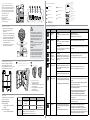
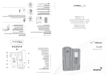
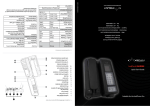
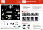
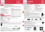
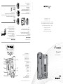
1. Oceana 800 Equipment Overview
Back Panel Connectors
11.
Mini USB Port
10.
Function Keypad
9.
Side SIM Card Port
(full size rapid user)
8.
Dial Keypad
7.
Screen Display
6.
Status LED
5.
Microphone
4.
Speaker
3.
Privacy Handset
2.
Interchangeable Mounting Cup
(Spring or Springless)
1.
a. RJ9 Privacy Handset
1
BEAM Communications Pty Ltd
8 Anzed Court, Mulgrave
Victoria, 3170, AUSTRALIA
5
6
2
3
7
8
9
4
b. RJ11/POTS interface
10
c. Auxiliary Device Port
d. DC power and accessory input
Quick Start Guide
11
e. Instant Messaging
Oceana 800
a
b
c
d
e
2. Close the SIM door, and ensure that it
“clicks” shut. This indicates the water
resistant seal has been engaged.
1. Turn the Terminal’s power OFF. Failure to turn
it OFF can result in corruption of your SIM card
memory.
1. Insert the SIM with gold contacts
facing down.
If your Service Provider has not installed the SIM card for you, follow these
steps to install.
The Side SIM port can be used on its own,
or in addition to the Rear port.
REAR SIM CARD
SIDE SIM CARD
2. SIM Installation
2. The Rear SIM is accessed from the rear of the
terminal. Undo the screw and remove the
cover.
3. Power the terminal back ON.
4. The SIM will automatically register on
the SIM service of the Side SIM.
Web: www.beamcommunications.com
3.
Information: [email protected]
Support: [email protected]
Tel: +61 3 8588 4500
Fax: +61 3 9560 9055
NOTE
Gold contacts on SIM must be facing downwards.
4.
The Side SIM Port only accepts full size SIM. If required, you can refit your SIM
to the outer card using adhesive tape as illustrated below:
3. Slide the tray guide into the open position.
(Refer to Image 3.)
www.beamcommunications.com
PART #: USRQSG006601
4. Once opened, raise the SIM tray and gently
insert the SIM card into the tray slot making
sure that the golden contacts are facing
downwards.
(Refer to Image 4.)
5.
5. Lower the tray and slide the tray guide into the
lock position.
6. Replace the SIM cover.
b
a
c
d
e
WARNING
DO NOT pull with force on the cables from the
rear of the Oceana 800. Please install strain relief
clamping for the antenna cables where required.
Correct installation of the antenna system is a
vital part of the Oceana 800 system, to ensure
reliable functionality, and drop-free calls.
2. Connect the antenna cable labelled “GPS” to
the SMA antenna connector labelled “GPS”.
Connect the antenna cable labelled “Inmarsat” to
the SMA antenna connector labelled “ISAT”.
SMA
GPS
Antenna
Cable
SMA
2
3
SMA
4
5
TNC
Satellite
Antenna
Cable
WARNING
Changes or modifications not expressly approved
by Beam Communications could void the
terminals warranty.
WARNING
To satisfy FCC RF exposure requirements for mobile
transmitting devices, a separation distance of
55cm or more should be maintained between the
antenna of this device and persons during device
operation. To ensure compliance, operations at
closer than this distance is not recommended.
There are eight (8) fixing holes available
for mounting the bracket to a wall. It is
recommended that at least 3 screws are used to
ensure the Terminal is mounted securely.
Alarm set
New voicemail
Call divert on
Missed call
Unread message
Bluetooth on
Status bar
Network
Signal strength
Screen
Info
Contacts
Left selection key
Navigation keys
Right selection key
Red key
Centre selection key
9. Oceana 800 Function Keys
1. Refer to the antennas installation guide
for antenna mounting and location
requirements.
5. Wall Mounting & Locking Bolt
USB connection
05:56
Green key
4. Antenna Connection
5. Connect the TNC (F) antenna cable end to
the Oceana 800 satellite connector
Keypad locked
Menu
a. RJ9 Privacy Handset
b. RJ11/POTS Interface
c. Auxiliary Port
d. DC power and accessory input
e. Instant messaging
4. Connect the GPS-SMA (F) cable end to the
Oceana 800 SMA connector
Local time
Oceana 800
Inmarsat
For the Oceana 800, the external cable
interfaces are at the rear of the terminal. The
cover panel creates the IP54 rating for the
electrical interface and retains the cables in
their respective channels. The cover panel is
fixed in place by 6 screws.
3.
Product name
7. Oceana 800 Dial Keypad
3. Access to rear connector bay
1
Fit the three (3) hooks on the mount
bracket into the three (3) large mounting
holes on the back of the terminal
2
3
Location
Button Mode
Action
LED/Sound
Mute Press
on/off
In a Call:
Mute the microphone (uplink) on the privacy
handset.
LED turns RED - Muted
LED turns OFF - Not muted
LED flashing Yellow - RJ11/POTS in use
Up/Down
In a Call:
Increase/decrease volume on speakerphone
or privacy handset.
Audio will sound louder/quieter with each press.
Out of Call:
Increase/decrease volume of incoming ring
tone on the speakerphone.
A beep will sound indicating the increased/decreased ring
tone volume
Brightness
dual button
simultaneous
press
(1 second)
Out of Call:
Enter LED brightness change mode. Press UP
and DOWN arrows to vary intensity. Mode will
automatically exit after 5 seconds after the last
button press.
All LED’s will change to WHITE and a single beep will sound
when entering brightness change mode.
Speakerphone
press ON/OFF
In a Call:
Terminate call if speakerphone mode is active
Activate speakerphone mode if Privacy Handset mode is active.
OR
+
A short double beep will sound when exiting change mode.
Slide the terminal down to “lock”
Final “lock” position
LED turns GREEN - Speakerphone mode active
LED turns OFF - Speakerphone mode not active
Out of Call:
Answer inbound call in speakerphone mode
Instant
Message (IM)*
Locking Bolt Installation
1. Remove the mounting cup
(See MANUAL for details)
2. Insert the bolt into the hole beneath the cup
and screw into place
3. Ensure the Terminal will not slide up off the
mounting bracket
4. Replace the mounting cup.
When Instant Message enabled/configured a
0->3 second press triggers an instant message.
A 7 second press will clear the instant message.
IM functionality disabled – No backlight, no colour
When Instant Message disabled no functionality.
IM button pressed LED changes from GREEN to solid RED (a
beep will sound when triggered)
Once first emergency message has been sent LED changes
from solid RED to flashing RED
Once remote acknowledgement of instant message, LED
changes from flashing RED to slow flashing YELLOW.
If audio tones for instant message is enabled:
8.Status LED
The Status LED indicates the terminal registration
state or any error conditions:
Special Modes of Operation
RED
In firmware upgrade mode all LED’s will
flash RED.
Transceiver (USB Bridge) Mode
•
In this mode all LED’s will flash GREEN.
No signal
Not registered
No SIM card
YELLOW
GREEN
A beep will sound from the buzzer when the Instant Message is triggered
DTR present on data
port
Unit registered and can
place a call.
A double beep will sound from the buzzer when the
Instant Message is cleared
Data call in progress
Call in progress OR
ILLUMINATED
•
•
•
FLASHING
Firmware upgrade mode
active
ALTERNATING
Red/Yellow - Short circuit on SAT antenna input
Firmware Upgrade Mode
•
IM functionality enabled but not triggered – LED should
be Green
Red/Green - Short circuit on GPS antenna input
Red/Yellow/Green - Internal communications error
Transceiver Upgrade Mode
Tracking*
When tracking enabled a momentary press
results in a tracking message being queued
for sending.
When tracking disabled no functionality.
LED On and Red - Tracking enabled and NO GPS fix
LED on and Green - Tracking enabled and GPS fix
LED Flashing Green - Track button has been pressed (beep
will sound from the buzzer). Will stay flashing for 5 seconds to
indicate message sending. OR Transceiver upgrade mode active.
LED Flashing Red - Firmware upgrade mode active
*This action is optional, only when the Tracking mode of your Oceana 800 is configured and activated.