1
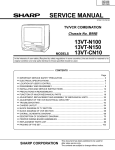
Service Manual
MT1130C
13” Color Television
VOLUME
CHANNEL
DOWN UP
DOWN UP
POWER
REMOTE SENSOR
THIS SERVICE MANUAL IS FOR MT1130C SUFFIX A , B ,
C AND D CRT USAGE
SUFFIX A
SUFFIX B
SUFFIX C
SUFFIX D
V451
5721-014ST37N
(37GDA86X)
5721-37CN030T
(370KSB22(SYB))
5721-026TT37N
(A34JFQ90X)
5721-030ZT37N
(A34JXV70X)
DY501
4993-117
4993-052
4993-110
4993-124
( ADJUSTMENT BY REMOTE CONTROL )
ADJUSTMENT MODE
The following adjustment items can be performed from menus by Remote Control as shown
below :
NOTE: The button combination and position on the Remote Control to select the
adjustment items is given on page 4.
1. Press the SHIFT + ADJ. MODE buttons on the Remote Control simultaneously to bring up
the adjustment mode menu screens shown below.
2. From the menu screen, press the + or - button on the Remote Control to select the item to
be adjusted.
3. Press the MENU button on the Remote Control to enter adjustment mode for the item
selected, and the display shown below appears :
OR
COLOR
32
RED CUTOFF
127
Example:
4. Use the + or - button on the Remote Control to adjust the data for the item selected.
5. When adjustment has been completed, press the SHIFT + ADJ. MODE buttons on the
Remote Control simultaneously to return to the main menu.
-3-
REMOTE CONTROL LAYOUT
VIDEO
METHOD OF RECALL V-BLOCK PASS NUMBER
If user forgets the V-Block Pass Number, call recall by the Service Remote Control or User
Remote Control.
1. If use the Service Remote Control, at the Pass Number entry menu, while holding down
[SHIFT] button and press the [Q.REV] button repeatedly four times.
2. If use the User Remote Control, at the Pass Number entry menu, while holding down
[VOLUME DOWN] button on the TV set and press number [3] button on the remote control
repeatedly four times.
3. The blinking “?” will be replaced with “!” after each press.
4. Release the [SHIFT] button or [VOLUME DOWN] button and then press [MENU] button. “VBLOCK SET” menu will be appearing on-screen with the user setting pass number.
-4-
IC, TRANSISTOR AND CRT COMPLEMENT
INTEGRATED CIRCUITS
IC101 TA87C-B6
IC102 CAT24CO4
IC301 TA1268N
IC311 NJ7809FA
Microcomputer
EEPROM
IF/Video/Chroma/Deflection
Voltage Regulator
IC501 AN5512
IC601 STR30130
IC671 NJ7805LD
Vertical Deflection Output
AVR
Voltage Regulator and Reset
Vertical Synchronizing
Horizontal Synchronizing
SD Signal Buffer
SIF Signal Buffer
Video Buffer Amplifier
Video Out
Service Mode Switching
Red Color Driver
Q452 2SC1473A(R)
Q453 2SC1473A(R)
Q551 2SC1473A(R)
Q552 2SD 1 877
Q601 2SC945(P)
Q801 2SC945(P)
Q802 2SA950(0)
Q803 2SC2120(0)
Blue Color Driver
Green Color Driver
Horizontal Driver
Horizontal Driver
Power On/Off Relay Driver
Audio Amplifier
Audio Amplifier
Audio Amplifier
TRANSISTORS
Q101 DTC143ZS
Q102 2SC945(P)
Q173 2SC945(P)
Q301 2SC945(P)
Q302 2SA733(P)
Q303 2SC945(P)
Q351 DTC143ZS
Q451 2SC1473A(R)
PICTURE TUBE
V451 37GDA86X
CRT (SUFFIX A)
V451 370KSB22(SYB) CRT (SUFFIX B)
V451
V451
A34JFQ90X
A34JXV70X
CRT (SUFFIX C)
CRT (SUFFIX D)
CHASSIS REMOVAL
1.
2.
3.
4.
5.
6.
Remove 4 screws (183) from Cabinet Back (AB) and remove Cabinet Back from rear.
Discharge anode lead at CRT chassis ground through a 10kohm resistor.
Disconnect anode lead from CRT.
Disconnect CRT Socket P.C. board (PCB-2) from CRT(V451).
Disconnect 3 connectors (CN501 (DY501), CN601 (L601) and LCN801) from Main P.C.
board (PCB-1).
When replacing chassis, reverse the above procedure making certain that all leads are
fastened in their original places.
CRT REMOVAL
CAUTION: Wear shatterproof goggles and exercise proper handling precautions when working
around high vacuum picture tubes.
1. Remove chassis per instructions under CHASSIS REMOVAL.
2. Remove Convergence Magnet Assembly (MG451) from neck of CRT.
3. Remove Deflection Yoke (DY501) from neck of CRT
4. Remove 3 wedges (158) from CRT
5. Remove Degaussing Coil (L601) from CRT
6. Remove braid wire (331) and spring (157) from CRT
7. Lay cabinet face down on some protective material.
8. Remove 4 CRT mounting screws (174).
9. Remove CRT from Cabinet Front (AA).
10. To install new CRT, reverse above procedure.
11. Perform purity and convergence adjustments.
-5-
INSTALLATION AND SERVICE INSTRUCTION
CAUTION: Use an isolation transformer when performing any service on this chassis.
SHUTDOWN CIRCUIT:
When the high voltage rises, there are simultaneous voltage increase
developed at terminal 6 of the Horizontal Output Transformer ( T671 ) and applied to pin 29 of IC301. If
excessive high voltage is produced, the increased voltage developed exceeds the rating of zener diode
D552 causing the Horizontal Oscillator to stop functioning and the high voltage system to shut down.
AFT ( AUTOMATIC FINE TUNING ) ADJUSTMENT
1.
2.
3.
Connect TV Test Pattern Generator (NTSC signal, Monoscope signal, 70dBu, channel 2) to EXT.
Antenna Terminal (TE1) through TV Channel Signal Generator.
Connect wire (+) of DC Digital Voltmeter to TP6 and wire (-) to TP4. (Figure 1)
Adjust T202 so that the DC Digital Voltmeter reading is 2.0V ± 0.1V.
FIG. 1
SUB COLOR AND SUB TINT ADJUSTMENT
1.
Connect TV Test Pattern Generator (NTSC signal, Color Bar signal, 70dB u , channel 6) to EXT.
Antenna Terminal (TE1) through TV Channel Signal Generator.
2. Connect positive lead of Oscilloscope to TP14 and negative lead to TP10.
3. Set Tint control to center position. (by Remote Control).
( NOTE: For steps 4, 5 and 6 below, refer to page 3 for Adjustment By Remote Control Method).
4. Go to Adjustment Mode (1) by remote control.
5. Select SUB COLOR and SUB TINT from Adjustment Mode (1) menu screen.
6. Adjust SUB COLOR and SUB TINT level (by using + or - button on remote control) so that waveform 1
& 4 (for SUB COLOR) and waveform 2 & 3 (for SUB TINT) is the same as shown in Figure 2.
FIG. 2
-6-
SOUND IF ADJUSTMENT
1.
2.
3.
Connect TV Test Pattern Generator (NTSC signal, 70dB u , channel 2) to EXT. Antenna Terminal
(TE1) through TV Channel Signal Generator. (Standard modulation is 400Hz at 25kHz deviation for
sound signal.
Connect positive lead of DC Digital Voltmeter to TP7 and negative lead to TP9.
Adjust T203 so that the DC Digital Voltmeter reading is 4.0V.
COLOR PURITY ADJUSTMENT
For best results, it is recommended that the purity adjustment be made in the final receiver location. If
the receiver will be moved, perform this adjustment with it facing East.
The receiver must have been operating 15 minutes prior to this procedure and the face plate of the CRT
must be at room temperature. The following procedure is recommended while using a Dot/Bar
Generator.
1. Check correct location of all neck components. ( Refer to Figure 3 )
2. Rough -in the static convergence at the center of the CRT, as explained in the static convergence
procedure.
3.
Set the Contrast control to minimum position and Brightness control as far maximum as possible
without causing the picture to “bloom”.
4. Apply green raster signal from Dot/Bar Generator to receiver.
5. Loosen the deflection yoke clamp screw and pull the deflection yoke toward the rear of the CRT.
6. Begin the following adjustment with the tabs on the round purity magnet rings set together. Slowly
separate the two tabs while at the same time rotating them to adjust for a uniform green vertical
band at the center of the CRT screen.
7. Carefully slide the deflection yoke forward to achieve green purity (Uniform green screen).
NOTE: Center purity is obtained by adjusting the tabs on the round purity magnet rings. Outer edge
purity is obtained by sliding the deflection yoke forward.
8. Check for red and blue field purity by applying red and blue raster signal alternately from Dot/Bar
Generator to receiver. Repeat steps 2 through 7, if required.
9. Tighten deflection yoke clamp screw.
10. Perform BLACK AND WHITE ADJUSTMENT procedure.
( CW : clockwise, CCW : counterclockwise )
FIG. 3
-7-
STATIC CONVERGENCE ADJUSTMENT ( Refer to Figure 3 and 4 )
IMPORTANT: Before proceeding, make sure the location of the convergence magnet assembly on the
neck of the CRT is as shown in Figure 3. The rear edge of this assembly must be positioned 65 mm
from the tip of the CRT base. If not properly positioned, convergence adjustment may be difficult, if not
impossible.
1. Apply dot or crosshatch pattern from Dot/Bar Generator to receiver. Reduce setting of Brightness
and/or Contrast controls to eliminate any blooming in pattern.
2. Observe the blue and red pattern appearing on the CRT screen. Locate the 4 pole magnet rings
and separate their adjusting tabs approximately the width of one tab.
3. Now rotate this pair of magnet rings as a unit without re-adjusting the spacing between the tabs.
This will minimize the separation between the blue and red dots (lines).
4. If the blue and red dots are not completely converged at this point, readjust the spacing between the
two tabs to complete convergence of the blue and red dots (lines), thus producing magenta dots
(lines).
5. If necessary, repeat step 2, 3 and 4 until proper convergence is achieved.
6. Observe the magenta (B/R) and green pattern now appearing on the CRT screen.
7. Locate the 6 pole magnet rings and separate their adjusting tabs approximately the width of one tab.
8. Rotate this pair of magnet rings as a unit without re-adjusting the spacing between the tabs. This
will minimize the separation between the magenta (B/R) and green dots ( lines).
9. If the magenta and green dots (lines) are not completely converged at these points, readjust the
spacing between the two tabs to complete convergence of the magenta and green dots (lines).
10. If necessary, repeat step 7, 8 and 9 until proper convergence is obtained.
To prevent accidental mis-adjustment of the magnets, apply a stripe of paint across all six rings and
onto the neck of the CRT.
FIG. 4
DYNAMIC CONVERGENCE ADJUSTMENT ( Refer to Figure 5)
Dynamic convergence (convergence of the three edges of the CRT screen) is accomplished by proper
insertion and positioning of three rubber wedges between the edges of the deflection yoke and funnel of
the CRT. This is accomplished in the following manner.
1. Turn the receiver ON and allow it to warm up for 15 minutes.
2. Apply crosshatch pattern from Dot/Bar Generator to receiver. Observe spacing between lines around
edges of CRT screen.
3. For the misconvergence shown in Figure 5 ( A ), tilt the deflection yoke down and insert wedge A
between deflection yoke and CRT.
4. For the misconvergence shown in Figure 5 ( B ), tilt the deflection yoke up and insert wedge B
between deflection yoke and CRT.
5. For the misconvergence shown in Figure 5 ( C ), tilt left side of the deflection yoke and slightly insert
wedge C between deflection yoke and CRT. Then, deeply insert wedges A and B between deflection
yoke and CRT.
6. For the misconvergence shown in Figure 5 ( D ), tilt right side of the deflection yoke and deeply insert
wedge C between deflection yoke and CRT. Then, slightly insert and/or extract wedges A and B
between deflection yoke and CRT.
7. Alternately change spacing between and depth of insertion of the three wedges until proper dynamic
convergence is obtained.
8. Use a strong adhesive tape to firmly secure each of the three rubber wedges to the funnel of the
CRT.
-8-
GREEN
RED
BLUE
GREEN
BLUE
RED
WEDGE B
RED
GREEN
BLUE
WEDGE C
RED
GREEN
BLUE
WEDGE A
DEFLECTION YOKE REAR VIEW
(A)
GREEN
BLUE
RED
BLUE
GREEN
RED
RED BLUE
GREEN
WEDGE A
DEFLECTION YOKE REAR VIEW
(C)
GREEN
RED
BLUE
WEDGE B
WEDGE B
BLUE
GREEN
RED
WEDGE C
BLUE
GREEN
RED
RED
GREEN
BLUE
(B)
DEFLECTION YOKE REAR VIEW
BLUE RED
GREEN
(D)
WEDGE A
DEFLECTION YOKE REAR VIEW
Fig. 5
FOCUS ADJUSTMENT
Adjust focus control, located on the Horizontal Output Transformer (T671), for maximum overall definition and fine
picture detail with Brightness and Contrast controls set at normal viewing levels.
BLACK AND WHITE ADJUSTMENT (CUTOFF / WHITE BALANCE)
The purpose of this procedure is to adjust the bias applied to the color picture tube for reproducing a quality
monochrome picture at all brightness levels and also to achieve maximum usable brightness. Confirm that proper
purity and AGC adjustments have been completed before starting this adjustment.
1.
Connect the TV test pattern generator (Monoscope pattern) to the EXT. antenna terminal via TV VHF/UHF
signal generator (NTSC signal, 70dB u).
2. Select Cutoff Mode by remote control, (refer to page 4 for remote control key combination and position) and
CUT OFF will be displayed on top-right screen for about 3 seconds. At the same time the data readings for
Cutoff and Gain in Adjustment Mode (2) will become as follows:
R CUTOFF: 50, G CUTOFF: 50, B CUTOFF: 50, G GAIN: 127, B GAIN: 127
3. Select Service Mode by remote control, (refer to page 4 for remote control key combination and position) and
TV screen becomes horizontal line.
4. Turn the Screen control (located under the flyback transformer) clockwise until any blue, green or red color
line appears.
5. Check the color of the line which appeared first, then turn the Screen control (located under the flyback
transformer) fully counterclockwise.
6. Adjust the cutoff level of the color which appeared first by remote control, (refer to page 4 for remote control
key combination and position) so that voltage between TP16 and TP15 (blue), TP14 (green) or TP13 (red) is
20 ± 1V.
7. Turn the Screen control (located under the flyback transformer) clockwise so that the bright color line can just
be seen.
8. Adjust cutoff levels other than the above by remote control, (refer to page 4 for remote control key combination
and position) so that the line color is white.
9. Press again Service Mode key by remote control, (refer to page 4 for remote control key combination and
position) to return to TV position. Monoscope pattern will appear on TV screen.
10. Adjust the contrast and brightness controls to make the picture dim. Adjust the Green and Blue Cutoff levels
by remote control, (refer to page 4 for remote control key combination and position) so that the picture is white.
11. Adjust the contrast and brightness controls to make the picture bright. Adjust the Green and Blue Gain levels
by remote control, (refer to page 4 for remote control key combination and position) so that the picture is white.
12. Repeat steps 10 and 11 so that the picture is white in both dim and bright conditions.
-9-
HORIZONTAL PHASE ADJUSTMENT
1. Connect TV Test pattern Generator (NTSC signal 70dB u, Monoscope Pattern) to Antenna T erminal
(TE) through TV Channel Generator.
(NOTE: For steps 2, 3 and 4 below, refer to page 3 for Adjustment By Remote Control Method).
2. Go to Adjustment Mode (2) by remote control.
3. Select H. PHASE from Adjustment Mode (2) menu screen.
4. Adjust H. PHASE level (by using + or - button on remote control) so that horizontal reading of test pattern
becomes the same value.
VERTICAL PHASE ADJUSTMENT
1. Connect TV Test pattern Generator (NTSC signal 70dB u, Monoscope Pattern) to Antenna Terminal
(TE) through TV Channel Generator.
(NOTE: For steps 2, 3 and 4 below, refer to page 3 for Adjustment By Remote Control Method).
2. Go to Adjustment Mode (2) by remote control.
3. Select V. PHASE from Adjustment Mode (2) menu screen.
4. Adjust V. PHASE level (by using + or - button on remote control) so that vertical reading of test pattern
becomes the same value.
VERTICAL AMPLITUDE ADJUSTMENT
1. Connect TV Test pattern Generator (NTSC signal 70dB u, Monoscope Pattern) to Antenna Terminal
(TE) through TV Channel Generator.
(NOTE: For steps 2, 3 and 4 below, refer to page 3 for Adjustment By Remote Control Method).
2. Go to Adjustment Mode (2) by remote control.
3. Select V. AMP from Adjustment Mode (2) menu screen.
4. Adjust V. AMP level (by using + or - button on remote control) so that picture fills the picture opening from top
to bottom and is proportionate to the width.
RF AGC ADJUSTMENT
1. Connect TV Channel Signal Generator to Antenna Terminal (TE).
2. Connect positive lead of DC Digital Voltmeter to TP5 and negative lead of DC Digital Voltmeter to TP4.
3. Adjust level of TV Channel signal Generator so that the output level is 57dB u. (Monoscope Pattern)
(NOTE: For steps 4, 5 and 6 below, refer to page 3 for Adjustment By Remote Control Method).
4. Go to Adjustment Mode (2) by remote control.
5. Select RF AGC from Adjustment Mode (2) menu screen.
6. Adjust RF AGC level (by using + or - button on remote control) so that the DC Digital Voltmeter reading is 6.0V
± 0.2V.
SUB BRIGHTNESS ADJUSTMENT
1. Connect TV Test Pattern Generator (NTSC signal, Color Bar Signal, 70dB u) to EXT. Antenna Terminal through
TV Channel Signal Generator.
(NOTE: For steps 3, 4 and 5 below, refer to page 3 for Adjustment By Remote Control Method).
2. Go to Adjustment Mode (1) by remote control.
3. Set the COLOR and CONTRAST of the TV set to minimum and the SUB CONTRAST and SUB BRIGHT to
'0' (using + or - button on remote control).
4. Adjust SUB BRIGHT level (by using + or - button on remote control) to obtain a dim pattern. (Refer to Fig.6)
DIM LIGHT
Fig. 6
- 10 -
TEST POINT
- 11 -
VOLTAGE CHART ( all in volts )
OPERATION CONDITION :
IC101
IC102
IC301
IC311
IC501
IC601
IC671
Q101
Q102
Q173
Q301
Q302
Q303
Q351
Q451
Q452
TERMINAL No
Volt
TERMINAL No
Volt
TERMINAL No
Volt
TERMINAL No
Volt
TERMINAL No
Volt
TERMINAL No
Volt
TERMINAL No
Volt
TERMINAL No
Volt
TERMINAL No
Volt
TERMINAL No
Volt
TERMINAL No
Volt
TERMINAL No
Volt
TERMINAL No
Volt
TERMINAL No
Volt
TERMINAL No
Volt
TERMINAL No
Volt
B
Volt
0.1
-0.7
-0.1
3.9
1.5
1.6
0.0
2.5
2.3
1
4.9
11
0.0
21
0.0
31
2.1
41
0.7
1
0.0
1
0.0
11
6.3
21
2.3
31
0.7
41
3.1
51
0.0
1
12.1
1
0.0
1
0.0
1
10.3
E
Volt
0.0
0.0
0.0
3.3
2.1
1.0
0.0
2.3
2.2
TINT, BRIGHT and COLOR CONTROL……….. CENTER
CONTRAST ………………………………………. MAXIMUM
COLOR BAR SIGNAL
2
3
4
5
6
7
8
0.0
0.0
0.0
5.0
5.0
5.0
0.0
12
13
14
15
16
17
18
0.0
5.0
5.0
5.0
2.3
0.0
0.0
22
23
24
25
26
27
28
0.0
0.0
0.0
0.0
3.9
4.7
4.9
32
33
34
35
36
37
38
2.3
5.0
0.0
5.0
4.5
3.1
2.0
42
5.0
2
3
4
5
6
7
8
0.0
0.0
0.0
2.0
3.1
0.0
5.0
2
3
4
5
6
7
8
3.8
3.0
0.0
4.6
0.0
2.0
0.7
12
13
14
15
16
17
18
4.8
0.0
0.0
4.8
4.8
4.8
3.3
22
23
24
25
26
27
28
0.8
5.1
5.2
5.6
8.3
3.0
2.0
32
33
34
35
36
37
38
1.2
6.9
5.4
0.0
2.8
3.2
3.1
42
43
44
45
46
47
48
4.9
4.7
2.4
2.0
9.0
4.0
9.0
52
53
54
55
56
0.0
2.8
5.2
5.8
0.0
2
3
0.0
9.0
2
3
4
5
6
7
8
12.5
0.0
24.2
13.7
0.7
-0.3
1.2
2
3
4
5
131.0 160.0 131.0 0.0
2
3
4
5
6
7
8
0.0
5.5
0.0
0.0
5.0
0.0
5.0
C
Volt
4.7
3.9
4.5
9.0
0.0
9.0
9.0
122.6
129.3
Q453
Q551
Q552
Q601
Q801
Q802
Q803
- 12 -
B
Volt
2.3
0.3
-0.2
0.7
0.6
6.7
8.0
E
Volt
2.2
0.0
0.0
0.0
0.0
7.4
7.4
9
0.0
19
0.6
29
4.9
39
0.0
10
0.6
20
0.7
30
0.0
40
0.7
9
9.0
19
2.6
29
2.1
39
3.0
49
8.4
10
4.4
20
2.5
30
1.0
40
6.3
50
8.2
9
23.8
C
Volt
132.0
126.0
0.1
6.7
0.0
16.0
CHASSIS WAVEFORM
- 13 -
SCHEMATIC DIAGRAM
PCB2 CRT
C130
100p
31
30
C556
10
/50V
R555
15k
32
CONTRAST
TINT
C451
470p B
C455
1000p
/500V
D681
1F4-E
26
R192 1k
27
28
3 9V 1
2
IN
Q551
2SC1473A (R)
R558
330
D607
1SS133
IC311
NJ7809FA
VOLTAGE
REGULATOR
R559
330
WF-9
C557
680p
/500V
R804
10k
D559
RD9R1ES2
C553
0.01 ZF
C554
100 /16V
Q552
2SD1877
!
! TE 1
C803
2200p
R802
10k
D802
1SS133
Q801
2SC945 (P)
R810
2.2
C805
0.1
C682
2200
/6.3V
6
C681
0.1
MYL
3
2
4
!
5
R603
270
10W !
CEM
R604
12k 1/4W
R605
330k 1/4W
RESET
CD
4
C608
22 /160V
G
5
3
CRITICAL
COMPONENTS
C678
100
/25V
RELIABLE AND PERFORMANCE
FOR CONTINUED RELIABILITY AND PERFORMANCE EXACT FACTORY REPLACEMENTS
ARE RECOMMENDED FOR ALL OTHER PARTS REPLACED. IF A SUBSTITUTE MUST BE USED
BE SURE ITS QUALITY AND SPECIFICATIONS ARE IDENTICAL TO THEORIGINAL PART.
4.
R334
R333
120k 1/2W 120k 1/2W
4
2
1
!
!
P1
AC120V
60HZ
!
R611
680
1/2W
D605
RD12ES2
SAFETY REQUIREMENTS COMPONENTS IN ACCORDANCE WITH
PRESENT SAFETY REGULATIONS. THESE COMPONENTS. MOST
ONLY BE REPLACED BY ORIGINAL PARTS.
16
TH601
!
!
D603
R610 1N4002E
1.8k
5W
CEM
C616
0.01
/250V
SCHEMATIC DIAGRAM NOTES:
1. ALL RESISTANCE VALUES ARE IN
.
k = 1000 . M = 1000k .
2. THE WATTAGE OF RESISTORS ARE 1/8W UNLESS OTHERWISE NOTED.
3. ALL CAPACITANCE VALUES ARE IN uF UNLESS OTFHERWISE NOTED.
p = pF = u u F.
3
RL601
! RELAY
1
THE DESIGN OF RECEIVER CONTAINS MANY CIRCUITS AND COMPONENTS INCLUDED
SPECIFICALLY FOR SAFETY PURPOSES. FOR CONTINUED PROTECTION. NO CHANGES
SHOULD BE MADE TO THE ORIGINAL DESIGN AND COMPONENTS SHOWN IN !
ON THE SCHEMATIC SHOULD BE REPLACED WITH EXACT FACTORY REPLACEMENT PARTS.
THE USE OF UNAUTHORIZED SUBSTITUTE PARTS MAY CREATE A SHOCKFIRE X-RAY
RADIATION OR OTHER HAZARD. SERVICE SHOULD BE PERFORMED BY QUALIFIED
PERSONNEL ONLY.
!
!
L602
FILTER
C605
0.01
/250V
KH
Q601
2SC945
(P)
R607
4.7k
SAFETY CRITICAL DEVICE
SAFETY
!
C604
0.01
/250V
KH
!
FU601
4A
/125V
RESET OUTPUT
Q802
2SA950 (O)
!
7
2
!
D601
RS104
!
R601
2.7
5W
MTL
C607
470 /200V
SP801
8 OHM
SPEAKER
F. BACK
ROUT
8
VIN
CN801
VOUT
C804
220 /16V
ERROR
START
V
R606
47 1/4W
1
!
PROTECT
R809
2.2 1/6W
R801 C801
470 4.7 /50V
IC671
NJ7805LD
!
LCN801
TP2
8
C609
33
/160V
C614
0.01
/250V
KH
! R812
10 1/2W
C806
1000 /16V
R807
150
C802
47 /16V
D8
HZT33
TUNER
R808
1 1/6W
R803
1k
VHF/UHF/CATV
D801
1SS133
R806
150
2
TP1
130V
R615
D606
47 1/4W 1S2473
IF
G
R674
1.8k 1W MTL
33V
C8
22 /50V
! TU1
UHV/VHF
75
BT
1
R613
4.7k 2W MTL
5V
BP
D671
1F4-E
F
S
3
R561
3.3k 5W CEM
R612
4.7k 2W MTL
R381
820 1/2W
6
4
C671
3300p
/400V
FB551
R562
C558
0.5
560p
/500V T552 1/2W
3
4
1
R672
2.2 1W
D672
1F4-E
! R671 C675
1000
2.2
1/4W /25V
WF-8
OUT
C664
100 /16V
25
R614
680 1/4W
24
R191 1k
23
R518
27k
1/6W
G
22
R351
220
C346
100p
B
C345
100p
B
C344
100p
B
21
C552
2.2 /50V
20
C1
10 /50V
R1
220 1/4W
C7
330 /16V
R151
1k 1/4W
R4 180k
C4
4.7 /50V
R152
1k 1/4W
BM
C676
1000
/25V
H.VCC
19
C501
2.2 /50V
R350
470
18
6
5
7
C672
3300p
/400V
11V
IC601
!
STR30130
SDA
R453
15k
1W
MTL
C683
0.01/400V
BUS
R321 220
17
D310
1SS133
16
R319 220
X301
3.58MHz
15
R
R322
3.3k
14
9
160V
15V
3.3V
13
C322
0.47
/50V
Q803
2SC2120 (O)
C673
!
3300p R673
/400V 2.2
1/4W
D673
1F4-E
VC/D
V. RAMP
!
T671
HORIZONTAL
OUTPUT
HV
R509
1.5
1/4W
WF-3
C510
3.3
/50V
B
GND
!
29
AFC2
V-SEP.
CUTOFF
ANALOG RGB
C210 C208
0.01 0.47
ZF
/50V
R805
470
C509
2.2
/50V
L.L
R508
33k
R510
5.6k
MATRIX
12
Q351
DTC143ZS
C508
1000
/25V
R507
56k
H-SEP.
BRIGHT
LPF
C505
0.1
MYL
C504
470p B
R501
1k
R563
330
2W
MTL
7
C512
100p B
C503
0.033
MYL
X-RAY
AFC1
8
HC/D
WPL
DEMO
D309
1SS133
11
32fH
VCO
WF-6
R463
3.3 !
1W
CEM FUSE
R675
1M
R336
2.2k
C555
10
/50V
D301
1S2473
R335
C304 0.01 68k 1/6W
D303
1S2473
R340 1M
R302
1.8k
R329
5.6k
33
2
D554 R557
1SS133 1k
D552
RD6R8ES2
R554
47k
R330
220k 1/6W
Q302
2SA733 (P)
R391 C391
75k 1/50V
R570
390
34
D555
3.3V
C380
1/50V
10
R123 C220
390 2200p B
R212
10k
35
SHARP
R341
820
9
TP4
GND
36
D553
1SS133
5
H.RAMP
SMOOTH
B
VCXO
C209
47
/16V
SF201
45.75MHz
37
C551
0.01
ZF
H-OUT
APC
PIF
VCC
8
38
Y-DL
C381
0.01ZF
SW
C206
1000p
B
TP3
IF
R308
1k
ACC
KILL
7
39
C305
1 /50V
9
FLYBACK
GENERATOR
R505
470
1/4W
PULSE
SHAPER
1
TP11
X-RAY
R556
5.6k
D311
1SS133
1
DET
COLOR
6
40
R331
180k
1/6W
4
OUTPUT
STAGE
WF-4
H. VCC
C562
1 /50V
R551
2.2k
1/4W
X551
503KHz
BLACK
STRETING
WPS
3.58
TRAP
DC REST
AFT
C211
4.7 /50V
5
T203
C221
0.01
ZF
4
41
R320 220
90
PIF
GND
3
42
CLAMP
LOCK LOCK
DET DET
2
43
C331
0.01
D302
1SS133
3
DRIVER
STAGE
6
C506
100/25V
D315
1SS133
44
R303
1.8k 1/4W
R307
330
R305
3.3k
C303
0.1 MYL
C214
0.01 ZF
45
BPF
Q
DET
1
R361
1k
R214
56k
46
C315
2.2
/50V
R503
100
1/4W
D501
1N4002E
VCC
RF
AGC
S105
VOL-DOWN
1000p MYL
C361
47
R
R134
12k
48
SIF
VCC
LIMIT
IC301
TA1268N
R133
5.6k
FM
DET
49
VCO
C306
0.1
MYL
C343
0.1 /50V
50
C342
0.1 /50V
51
SIF
GND
G
52
R328
2.2k
C308
10
/50V
R342
820
53
C341
0.1 /50V
54
R343
820
55
D308 1S2473
56
R362
39K
GND
TP9
R344
10k
VSS
4
T202
VCO
C362
100p
D312 1SS133
SDA
3
C212
4.7
50V
C231
0.01 ZF
WC
SCL
2
E2
E1
E0
R132
3.3k
1
C213
4700p
B
C317
0.01
C319
10p CH
VCC
CF201 L203
4.5MHz 22uH TP7
BPF
SIF
C320
0.022 ZF
5
C232
47
/16V
R301
1.8k
6
C318
47
/16V
L361
5.6uH
C218
47p
CH
R220
1k
7
CF301
4.5MHz
TRAP
Q301
2SC945 (P)
3
WF-1
IC501
AN5512
VERTICAL
DEFLECTION
OUTPUT
C601
0.1
/AC125V
R110
22k
R131
3.3k
S101
POWER
8
IC102
M24C02
S102
CH-UP
Q303
2SC945 (P)
VIDEO
TP8
3
2
2
S103
CH-DOWN
R127
270k
1/4W
R129
10k
R179
18k
1/4W
R176
10K
1/4w
L301
15 uH
R306
330
1
SCL
JL102A
D561
1F4-E
C507
0.047
MYL
WF-5
R218
1k
AGC
JL102
CN501
R116
1k
C217
47p
CH
S104
VOL-UP
!
DY501
VERTICAL HORIZONTAL
DEFLECTION YOKE
WF-7
R105
1k
1
R3
10k
JL102B
R332
1k 1/4W
21
1
C326
1 /250V
20
3
C611
1000 /25V
!
!
D602
1N4004E
C602
0.01 /250V KH
!
L601
DEGAUSSING
19
4
CN601
18
4551-2011602D
WF-2
5
R178
56k
TP6
AFT
R113
10k
R112
22k
R114
1k
R105
1k
17
GND
R181
33k
R177
33k
6
R461 R462
330 1.5k
1/6W 1/4W
R459 R460
330 1.5k
1/6W 1/6W
C674
10
/250V
16
7
C560
0.39
/200W
15
TP10
8
C454
1000p
/2kV
24V
14
JL101
Q453
1473A (R)
GREEN
C561
680p/2KV
C559
4300p
1.6kV
13
D306
1SS133
R458
1.5k
1/4W
C511
100 /25V
12
Q173
2SC945 (P)
R180
68k
1/6W
9V
9V
R137
15k
C129
100p
B
R457
330
1/6W
! V451
CRT
9
TP14
Q452
1473A (R)
BLUE
R504
15k
11
C177
270p
Q101
DTC143ZS
C127
1000p B
R519
56k
1/6W
10
R
9
POWER
8
B
7
OSD CONT 2
6
OSD CONT 1
5
22
G
R120 1k
R121
5.6k 1/4W BLK
R122
B
5.6k 1/4W
R123
G
5.6k 1/4W
R124
R
5.6k 1/4W
BLK
4
23
ADJ MODE 3 HD-OSD
3
24
NC
2
TP5
AGC
R136
100k
C109
R119 1k 1/4W 8.2p CH
AFC
VD-OSD
OSC2
MENU COLOR
TEST
OSC1
KEY IN
XIN
VCHIP SEL
XOUT
1
R106
22k
MAIN/SAP
GND
RESET
L101
47uH
X101 8MHz
C103
4.7/50V
25
TV/VIDEO
26
REMOTE
27
NC
28
LANGUAGE
SCL
29
H. SYNC
30
SERVICE
31
ST/MONO
32
POWER IN
33
V-BLOCK
SDA
C112
680pB
C111
680pB
C102 0.1
GND
34
NC
35
VCC
C101 0.1
36
VIDEO INPUT
37
V-SYS
38
VIDEO INPUT
39
GND
40
Q102
2SC945 (P)
NC
41
C106
30p CH
C104
27p CH
C105
27p CH
R102
4.7k
R101
4.7k
C108
0.022
ZF
C107
100 /10V
IC101
TMPA8700CPN
U-COM
42
5V
Q451
1473A (R)
RED
JL101B
5P
R
G
B
JL101A
5P
R
G
B
!
SU451
R473
220
C126
560p B
R456
2.7k 1/4W
R455
2.7k 1/4W
C453
470p B
R126
22k
R128
2.2k
1/6W
5V
R104 100
R454
2.7k 1/4W
TP15
TP13
R472
220
GND
R146 1 k
R103 100
R452
15k
1W
MTL
RX101
REMOTE
SENSOR
VCC
R471
220
VOUT
C180
100p B
TP16
R451
15k
1W
MTL
R142
1k
1/4W
C452
470p B
4551-2011601D
C606
0.01 /250V
PCB1 MAIN