1
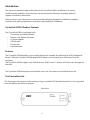
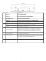
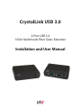
CrystalLink USB 3.0
2-Port USB 3.0
100m Multimode Fiber Optic Extender
Installation and User Manual
FCC Radio Frequency Interference Statement Warning
This device complies with Part 15 of the FCC rules. Operation is subject to the following two conditions:
(1) this device may not cause harmful interference, and
(2) this device must accept any interference received including interference that may cause undesired
operation.
CE Statement
The CrystalLink USB3.0 is in conformity with European Standard EN 55022, EN 55024, EN 61000-3-2, and EN
61000-3-3.
IC Statement
This Class B digital apparatus complies with Canadian ICES-003.
Contents
Introduction ............................................................................................................. 3
Product Contents ................................................................................................................................ 3
Features ................................................................................................................................................... 3
The Transmitter Unit .......................................................................................................................... 4
The Reveiver Unit ................................................................................................................................ 5
Installation Guide .................................................................................................... 6
Requirements ....................................................................................................................................... 6
Fiber Optic Link Cabling ................................................................................................................... 6
Installing the CrystalLInk USB3.0 System ................................................................................... 7
Preparing Your Site ............................................................................................................................. 7
Preparing Your Computer ................................................................................................................ 7
Connecting a USB 3.0 Device ........................................................................................................ 11
Installing the Receiver Unit ............................................................................................................ 11
Installing the Transmitter Unit ..................................................................................................... 11
Checking the Installation ............................................................................................................... 12
Compatibility ...................................................................................................................................... 12
Troubleshooting .................................................................................................... 13
Contacting Technical Support .............................................................................. 15
Warranty Information ........................................................................................... 15
Obtaining Warranty Service ................................................................................. 16
Contacting Sales .................................................................................................... 16
Contacting Technical Support .............................................................................. 16
Technical Glossary ................................................................................................. 17
USB Connectors ................................................................................................................................. 17
DupTransmitter LC Crossover ....................................................................................................... 17
Specifications ......................................................................................................... 18
Introduction
This document provides product information for the CrystalLink USB3.0, installation instructions,
troubleshooting guidelines, and instructions for contacting Rose Electronics regarding technical
support and warranty information.
The instructions in this document assume a general knowledge of computer installation procedures,
familiarity with cabling requirements, and some understanding of USB devices.
CrystalLink USB3.0 Product Contents
Your CrystalLink USB3.0 is packaged with:
•
Transmitter unit (Local Extender)
•
Receiver unit (Remote Extender)
•
AC power adapter
•
USB 3.0 cable
•
Power cable
•
User Document
Features
The CrystalLink USB3.0 enables users to extend beyond the standard 3m cable limit for USB 3.0 peripheral
devices. With the CrystalLink USB3.0, certain USB 3.0 devices can be located up to 100 meters from the
computer.
The CrystalLink USB3.0 supports only USB 3.0 devices. USB 2.0 and 1.1 devices will not function through this
extender.
The CrystalLink USB3.0 comprises two individual units: the Transmitter unit and the Receiver unit.
The Transmitter Unit
The Transmitter unit connects to the computer using a standard USB 3.0 cable. Power for this unit is provided
from the USB port on the host computer.
Front View
4
Rear View
ITEM TYPE
1
2
3
DESCRIPTION
Power ON
Unit is powered properly.
Power OFF
Unit is not powered or not powered properly.
Status Blinking (1Hz)
Waiting for connection to Receiver.
Status ON
Transmitter and Receiver are linked and operating normally.
Status OFF
Fault detected; power cycle required.
Host ON
SuperSpeed Host detected on upstream facing port.
Host OFF
SuperSpeed Host not detected.
Not required in normal operation. An optional 5V power supply can be
connected to the Transmitter unit to provide power if the USB port on
the host PC is not capable of delivering sufficient power to the unit.
4
Power Port (optional)
5
Configuration Port
Reserved for manufacturer use.
6
USB 3.0 Type B port
Used to connect the Transmitter unit to the host computer. Port accepts
locking or non-locking USB 3.0 Type B connectors.
7
Link Port (Dup Transmitter LC)
Extension link Dup Transmitter LC fiber optic transceiver port.
5
The RECEIVER Unit
The Receiver unit has two USB Type A ports for USB 3.0 devices. The RECEIVER unit allows you to connect up
to two USB 3.0 devices directly. The RECEIVER unit is powered by an external AC adapter and can supply up to
900mA to each USB port.
Front View
Front View
Rear View
Rear View
ITEM
TYPE
DESCRIPTION
USB 3.0 Type A ports
Used to connect USB 3.0 device(s) to the RECEIVER unit. Ports accept
locking or non-locking USB 3.0 Type A connectors.
Power ON
Unit is powered properly.
Power OFF
Unit is not powered or not powered properly.
Status Blinking (1Hz)
Waiting for connection to TRANSMITTER.
Status ON
TRANSMITTER/RECEIVER are linked and operating normally.
Status OFF
Fault detected; power cycle required.
Host ON
SuperSpeed Host detected on upstream facing port.
Host OFF
SuperSpeed Host not detected.
5
Power Port
Connects to the locking AC power supply. Required on the Receiver unit
for correct operation.
6
Config Port
Reserved for manufacturer use.
7
Link Port (Dup Transmitter
LC)
Extension link Dup Transmitter LC fiber optic transceiver port.
1
2
3
4
6
Installation Guide
Example Application
USB 3.0 Camera
Computer & Monitor
USB 3.0
up to 100m over
multimode fiber
TRANSMITTER
RECEIVER
Assembly Line
Requirements
To complete installation of the CrystalLink USB3.0, you will also require the following items that are not
included with the product:
• USB 3.0 compatible computer (host computer) with a USB 3.0 compliant operating system
• USB 3.0 compatible device
• 2-strand 50/125μm multimode (MMF) fiber optic cable with Dup Transmitter LC connectors
Fiber Optic Link Cabling
The Transmitter and Receiver units are interconnected by fiber optic cabling. This cabling must be:
• 50/125μm multimode fiber (MMF)
• Terminated with Dup Transmitter LC connectors
The following maximum distances are achievable depending on the application and cabling standard:
• Using OM3, up to 100m is achievable with USB 3.0 cameras, and up to 50m for all other applications.
• Using OM2, up to 50m is achievable for all applications.
These maximum distances include any fiber patch cords or patch panel interface.
If premise cabling will be used for the installation, then the distances provided above must be met when
measuring from Transmitter to Receiver, inclusive of the premise cabling and the patch cables. All cables
must meet the ratings specified. Patch cables must be terminated with Dup Transmitter LC connectors.
7
Installing the CrystalLink USB3.0 System
Preparing Your Site
Before you can install the CrystalLink USB3.0, you need to prepare your site:
1.
2.
3.
Determine where the computer is to be located and set up the computer.
Determine where you want to locate the USB device(s).
Ensure fiber optic cabling is in place, prepared, properly terminated, and within the maximum
distances as defined for the cabling standard used.
Preparing Your Computer
The CrystalLink USB3.0 does not support suspend modes of operation. As such, your computer
should be configured to not go into “suspend mode” or to “suspend” the USB ports.
To perform the changes:
Windows (7/8)
To disable “suspend” settings on your computer:
1.
Open Control Panel. Open Power Options.
8
a. Click on Change Plan Setting
2.
Select “Never” for “Put the computer to sleep” for all the configurations presented.
a. Click Change advanced power settings.
8
b. Expand “USB settings”
c. Expand “USB selective suspend setting”
3.
Select “Disabled”.
OS X
To disable “suspend” settings on your computer:
1.
Open System Preferences and select Energy Saver.
9
2.
For both Battery and Power Adapter power settings, move slider bar to “Never” for “Computer Sleep”.
3.
In the popup warning window, click OK.
10
Connecting a USB 3.0 Device
1.
2.
Install any software required to operate the USB device(s). Refer to the documentation for the USB
device(s), as required.
Connect the USB device to the device port on the Receiver unit. If you are using a USB3.0 Vision
compliant locking USB cable, then you can use the locking knobs to lock the cable to the port on
the Receiver.
3.
Check that the device is detected and installed properly in the operating system.
Installing the Receiver Unit
1.
2.
3.
Place the Receiver unit near the USB device(s).
Plug the power adapter into a suitable AC outlet.
Connect the power adapter to the Receiver unit and twist the connector to lock the power
connector into the Receiver unit.
Installing the Transmitter Unit
1.
Place the Transmitter unit near the computer.
2.
Connect the link cable to the Transmitter and the Receiver.
With Surface Cabling
• Plug one end of the fiber optic cabling (not included) into the Link port on the Transmitter unit.
• Plug the other end of the fiber optic cabling into the Link port on the Receiver unit.
With Premise Cabling
• Plug one end of a fiber optic patch cord (not included) into the Link port on the Transmitter unit.
• Plug the other end of the patch cord into the fiber optic information outlet near the host
computer.
• Plug one end of the 2nd fiber optic patch cord (not included) into the Link port on the Receiver
unit.
• Plug the other end of the 2nd patch cord into the fiber optic information outlet near the USB
device.
3.
Install the supplied USB 3.0 cable between the Transmitter and a USB 3.0 port on the host computer.
Checking the Installation
1.
On the Transmitter and Receiver units, check that the Power, Status, and Host LEDs are on and solid. If
the Host or Status LEDs are permanently off, then the cabling between the Transmitter and Receiver
unit may not be installed properly or is defective.
2.
For Windows users, open Device Manager to confirm that the CrystalLink USB3.0 has installed
correctly.
Expand the entry for Universal Serial Bus controllers by clicking the + sign. If the CrystalLink
USB3.0 has been installed correctly, you should find it listed as two “Superspeed Hub”s, or “3.0
Hub”s”.
3.
For Mac OS X users, open the System Profiler to confirm that the CrystalLink USB3.0 has installed
correctly.
In the left hand column under Hardware, select “USB” and inspect the right hand panel. If the
CrystalLink USB3.0 has been installed correctly, you should find it listed as a “Hub” under the USB
SuperSpeed Bus.
4.
If the CrystalLink USB3.0 is not detected correctly or fails to detect, please consult the
Troubleshooting section in this guide.
Compatibility
The CrystalLink USB3.0 complies with USB 3.0 specifications governing the design of USB devices. However,
Rose Electronics does not guarantee that all USB 3.0 devices are compatible with the CrystalLink USB3.0, as
there are a number of different configurations that may impact the operation of USB 3.0 devices over
extended distances.
12
Troubleshooting
The following table provides troubleshooting tips. The topics are arranged in the order in which they should
be executed in most situations. If you are unable to resolve the problem after following these instructions,
please contact Technical Support for further assistance.
PROBLEM
All LEDs on
TRANSMITTER
unit are off.
CAUSE
• The TRANSMITTER unit is not
SOLUTION
1. Ensure that the USB connection between
the TRANSMITTER and host computer is
properly installed.
receiving power from the USB
port or the (optional)
TRANSMITTER AC adapter.
2. Move the USB connector to another USB port on
the host computer.
All LEDs on
RECEIVER
unit are off.
• The RECEIVER unit is not
1. Ensure that the AC power adapter is properly
receiving power from the AC
adapter.
connected to the RECEIVER unit.
2. Check that the AC adapter is connected to a live
source of electrical power.
Status LEDs on
both the
TRANSMITTER
and RECEIVER are
blinking.
• There is no connection between
the TRANSMITTER unit and
RECEIVER unit.
• The TRANSMITTER unit is not
connected to
a USB 3.0 port
• The host computer does not
support USB 3.0
1. Ensure that the host computer supports USB 3.0,
refer to manual for the computer to confirm.
2. Ensure the TRANSMITTER unit is connected to a USB
3.0 port. The centre of the port should be blue.
Another colour, such as black usually indicates a USB
2.0 port
3. Ensure that a multimode fiber optic cable with
crossover is connected between the TRANSMITTER
and RECEIVER units.
4. Connect a fiber optic crossover patch cord
between the TRANSMITTER and RECEIVER
units. Recheck operation of the system.
Status LED is off
on one or both
units
• The computer went into
1. Power cycle the RECEIVER unit and the
suspend, hibernate or sleep
mode.
• The computer tried to suspend
the USB 3.0 port that the
TRANSMITTER is connected to.
devices connected to the RECEIVER
2. Power cycle the TRANSMITTER and RECEIVER
units, and the devices connected to the
RECEIVER
3. Follow the steps in “Preparing Your Computer” on
page 7 to disable suspend modes on your computer.
Refer to your operating system’s manual for
13
PROBLEM
Host LED on
TRANSMITTER/
RECEIVER units are
off.
CAUSE
• The host computer is not
SOLUTION
1. Disconnect all USB devices from the RECEIVER unit.
powered on.
2. Disconnect the TRANSMITTER unit from the
• The TRANSMITTER unit is not
computer.
connected to the computer
(when used with the optional
TRANSMITTER AC adapter).
• The CrystalLink USB3.0 is
3. Disconnect the RECEIVER unit from the AC power
adapter.
4. Reconnect the TRANSMITTER unit to the computer.
malfunctioning.
5. Reconnect the RECEIVER unit to the AC power
adapter.
6. In the Universal Serial Bus controllers section of
Device Manager, check that theCrystalLink USB3.0 is
recognized as two “Superspeed Hub”s or two 3.0
Hub”s
It may be recognized as “Superspeed Hub”, “3.0
Hub” or by other names, depending on the
operating system and driver installed.
14
All LEDs on both
the TRANSMITTER
unit and
RECEIVER unit are
on
but the USB device
does not operate
correctly, or is
detected as an
“Unknown Device” in
the operating
system.
• The USB device is
1. Disconnect the CrystalLink USB3.0 from
malfunctioning.
the computer.
• The computer does not
2. Connect the USB device directly to the USB port on
recognize the USB device.
the computer.
• The application software for
3. If the USB device does not operate properly,
the device is not operating.
consult the user documentation for the device.
• The CrystalLink USB3.0 is
4. Update your system BIOS, chipset, or USB Host
malfunctioning.
controller drivers from your System/Mother board
manufacturer’s website.
5. If the USB device operates properly when directly
connected to the computer, connect another
device (of a different type) to the CrystalLink
USB3.0. Connect the CrystalLink USB3.0 to the
computer.
6. If the second USB device does not operate, the
CrystalLink USB3.0 may be malfunctioning.
Contact Technical Support for assistance.
7. If the second USB device does operate properly, the
first device may not be compatible with
the CrystalLink USB3.0.
15
Contacting Technical Support
If you are experiencing problems not referenced in the Troubleshooting section, you may contact
Rose Electronics Technical Support.
16
Technical Glossary
USB Connectors
USB cables have two classes of connectors. The Type A connectors are used to connect the cable from a
USB device to a Type A port on a computer or hub. The Type B connectors are used to attach the USB cable
from a USB host to a USB device or hub. There are full-sized, mini, and micro variants of both type A and B
connectors.
USB 3.0 introduces changes to the connectors. USB 3.0 and USB 2.0 Type A connectors are the same shape
and size and are compatible with each other. However, the USB 3.0 Type B connector will not fit in a USB 2.0
Type B port, though a USB 2.0 Type B connector will fit into a USB 3.0 Type B port.
Type A USB 3.0 and 2.0 Port
Type A USB 2.0
Connector
Type B USB 2.0 Port
Type A USB 3.0
Connector
Type B USB 2.0
Connector
Type B USB 3.0 and 2.0 Port
Type B USB 3.0
Connector
DupTransmitter LC Crossover
When a crossover fiber-optic cable is called for, the cable has the transmit signal on one end connected to
the receive signal at the other end.
17
Specifications
Operating Distance
Up to 100m (330 ft)
USB Device Support & Throughputs
USB 3.0 up to 5Gbps
USB Host Support
xHCI controllers (Intel, AMD, Renesas (NEC), Fresco, AsMedia)
AC Adapters
100-240V AC Input, 5V DC Output, Locking
Power Available to USB Device at
Receiver
900mA for each USB Port
Transmitter Unit
USB Connector
1 x USB 3.0 Type B Locking Receptacle
Link Connectors
1 x Duplex LC Fiber Connector
Dimensions
100mm x 76mm x 26mm (3.94” x 2.99” x 1.02”)
Receiver Unit
USB Connectors
2 x USB 3.0 Type A Locking Receptacles
Link Connectors
1 x Duplex LC Fiber Connector
Dimensions
100mm x 76mm x 26mm (3.94” x 2.99” x 1.02”)
Environmental
Operating Temperature Range
0°C to 40°C (32°F to 104°F)
Storage Temperature Range
-20°C to 70°C (-4°F to 170°F)
Operating Humidity
20% to 80% relative humidity, non-condensing
Storage Humidity
10% to 90% relative humidity, non-condensing
Compliance
EMC
FCC (Class B), CE (Class B)
Machine Vision
AIA USB3 Vision (upon standard release)
Environmental
RoHS2
18