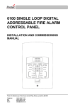
1
MODEL 132
VCG/NOISE
GENERATOR
@ - 1981
- Wavetek
THIS DOCUMENT CONTAINS INFORMATION PROPRIETARY TO
WAVETEK AND IS SOLELY FOR INSTRUMENT OPERATION AND
MAINTENANCE. THE INFORMATION IN THIS DOCUMENT MAY
NOT BE DUPLICATED IN ANY MANNER WITHOUT THE PRIOR
APPROVAL IN WRITING OF WAVETEK.
SAN DIEGO
9045 Balboa Ave., San Diego, CA 92123
P. 0 Box 651, San Diego, Calif. 92112
Tel 7141279-2200 TWX 91 O-335-2007
Manual Revision: 10181
Instrument Release: U-l 0180
CONTENTS
Section One
SPECIFICATIONS
Physical
Section Two
and
Electrical
Specifications
. . . . . . . . . . . . . .
OPERATION
......................
Inspection
Operating Controls ....................
......................
Operation
Section Three
Description
. . . . . . . . . . . . . . . . . . . .
11
MAINTENANCE
Introduction ......................
Recommended Test Equipment ................
Checkout and Calibration ..................
Troubleshooting .....................
Section Five
3
4
7
CIRCUIT DESCRIPTION
General
Section Four
1
13
13
13
16
DATA PACKAGE
Introduction ......................
................
Recommended Spare Parts List
21
21
SCOPE OF MANUAL
SCOPE OF EQUIPMENT
This manual contains instructions for operating, testing, and maintaining the Wavetek Model 132 VCG/
Noise Generator. The Wavetek product-improvement
program ensures that the latest electronic developments
are incorporated into the Wavetek instruments by the
addition of circuit and component changes as rapidly
as development and testing permit. Due to the time required to document and print this manual, it is not
always possible to incorporate these changes into the
manual. In this case, data will be found on engineering
change sheets at the back of the manual. If there are no
change sheets, the manual is correct as printed.
The Model 132 is a source of analog and digital noise,
as well as a precision source of sine, triangle and square
waveforms. Noise outputs, or waveforms can be used
individually, or combined to provide selectable, calibrated signal-to-noise and noise-to-signal ratios to
+60 dB. Waveforms can be varied over a frequency
range of 0.2 Hz to 2 MHz. Length of the digital sequence is selectable to a maximum of 220 - 1 bits.
Clock rates, variable from 160 Hz through 1.6 MHz,
give added versatility to the noise generator. These
clock rates allow selectable noise bandwidths variable
from 10 Hz to 100 kHz.
SAFETY
r
via the facil ty i powe rwiring. Do not
Thi s instrument i wire
s dfor earth g ounding
ith two wir extension
e
cords, plug adapter setc.
bYPa ss earth grou dingn w
BEFORE PLUGGING IN the instrument, comply with installation instructions.
t
sremoved.
MAINT ENANCE may requir power
e
on w thi th einstrumen cover
l
e of the elect rica hl azards.
shoul dbe don eonly by qualified personne awar
WARNING notes call attention t
operations.
possibleo injury or death hazards i
subsequentn
CAUTION notes call attention to possible equipment damage in subsequent operations.
1
SECTIO N
SPECIFICATIONS
VERSATILITY
HORIZONTAL PRECISION
Waveforms
Sine YJ , square I-I , triangle 2/ waveforms
and analog noise M.r , or digital noise l-u--L
Dial Accuracy
*2% of full scale, 1 Hz to 2 MHz
Frequency Range of Signal
0.2 Hz to 2 MHz in 6 decade ranges
Frequency Vernier
One turn equals 1% of full scale.
Ranges
x 10
X l 00
X1K
X10K
XIOOK
X1M
0.2 Hz to 20 Hz
2 Hz to 200 Hz
20 Hz to 2 kHz
200 Hz to 20 kHz
2 kHz to 200 kHz
20 kHz to 2 MHz
Function Outputs
Sine \ , square f-l~ , and triangle 2/ selectable,
with 60 d B step attenuator in 10 d B steps and overlapping calibrated vernier; 5Oa output impedance,
20 V p-p into open circuit and 10 V p-p into 5Oa
load from 5Oa source impedance.
Sync Output
Greater than 1 V p-p square wave into open circuit at
6OOa output impedance.
DC Offset
*5 V offset (22.5 V offset into 5Ofi load) controlled
from rear panel; peak amplitude limited by the dynamic range of the amplifier output.
VCG - Voltage Controlled Generator
Frequency of the generator may be dc-programmed,
or ac-modulated by external 0 to *5 V signal. Voltage
control circuitry is capable of 1000: 1 deviation. The
VCG amplifier has a 100 k H z bandwidth and a slew
rate of 0.1 V&s. The instantaneous frequency is the
result of the sum of the dial setting and the externally
applied voltage.
Stability
+0.05% for 10 minutes
Short term
+0.25% for 24 hours
Long term
Percentages apply to amplitude, frequency, and dc
offset.
Time Symmetry
*I % through XIOOK range
VERTICAL PRECISION
Sine Wave Frequency Response
Amplitude change with frequency less than:
0.1 d B from 0.2 Hz to 200 k H z
0.5 d B from 0.2 Hz to 2 MHz
PURITY
Sine Wave Distortion
Less than:
0.5% on X10, X100, X1K,X 1 0 K ranges
1.0% on XIOOK range
All harmonics 30 d B down on Xl MHz range
Square Wave Rise and Fall Time
Less than 50 ns terminated into SOQ
NOISE
outputs
Pseudo-random analog or digital noise
h
wit a maximum
of 20 V p-p excursion (open circuit) with 60 d B step
attenuator in 10 dB steps and overlapping calibrated
vernier.
Sequence Lengths
Push buttons on the front panel provide a sequence
length of 21° - 1, 215 - 1, or 220 - 1.
1
Noise Cl o c k Frequency
Switch selectable noise frequencies are listed
Analog Noise
Bandwidth
Clock Frequency
10 Hz
100 Hz
1 kHz
10 kHz
100 kHz
160 Hz
1.6 kHz
16 kHz
160 kHz
1.6 MHz
OPERATIONAL MODES
FUNC Function Mode - Provides the selected
form at the main output.
S/N Signal-to-Noise operation adds noise to a selected
signal of constant amplitude. The signal-to-noise ratio
is variable from 0 to +60 dB.
N/S Noise-to-Signal operation adds a selected signal
to a constant amplitude noise. The noise-to-signal ratio
is variable from 0 to +60 dB.
FM Frequency Modulation - Provides random modulation of the frequency of the generator. The S/N - N/S
(dB) ratio control also controls the amount of frequency deviation.
NOTE
When noise is added to the signal output,
specifications apply up to 200 kHz and
the square wave rise time is dera ted by
a factor of 10. In the clock range of
1.6 MHz, the maximum calibrated signalto-noise ratio is 30 d B
ENVIRONMENTAL
Temperature
All specifications listed, except stability, are for 25’C
*5’C. For operation from O°C to 55’C, derate all
specifications by factor of 2.
MECHANICAL
Dimensions
8% inches wide, 5% inches high, 11% inches deep
Weight
8 Ibs net, 12 Ibs shipping
Power
105 V to 125 V or 200 V to 250 V, 50 Hz to 400 Hz.
Less than 15 watts.
NOTE
All specifications apply for frequencies
obtained when dial is between 0. 1 and
2.0 and at 10 V p-p in to a 50 ohm load.
It is possible to stop the generator from
oscillating by applying a negative VCG
voltage when the dial is already set at
minimum frequency. VCG inputs up to
30 V will not permanently damage the
ins trumen t.
SECTION l
OPERATION
2.
3.
INSPECTION
The following procedures should be performed to assure the user that the instrument has arrived at its
destination in satisfactory operating condition. Complete calibration and checkout instructions are provided in Section 4 to determine compliance with electrical specifications.
4.
5.
6.
Checking Visually
7.
After carefully unpacking the instrument, visually inspect the external parts for damage to knobs, dials,
indicators, surface areas, etc. If damage is discovered,
file a claim with the carrier who transported the instrument. Retain the shipping container and packing
material for use in case reshipment is required.
8.
9.
10.
Checking Electrically
11.
NOTE
lnstrumen ts are normally shipped connected for 115 V power unless 230 V
power is ordered. Refer to the end of
this section for conversion instructions.
The steps in this paragraph provide a quick checkout
of the instrument operation. If electrical deficiencies
exist, refer to the WARRANTY in the front of this
manual. The following test equipment is recommended
for performing this electrical inspection:
Name
Required
Characteristics
12.
13.
14.
15.
16.
Oscilloscope
Plug-l n
Plug-l n
Counter-Timer
To 30 MHz
Dual channel
Peak mV measuring
capability
To 2 MHz with 5-digit
resolution
17.
18.
19.
1.
Turn FREQ HZ selector to the Xl K position.
(This connects ac power to the unit and establishes the frequency multiplier.)
Depress MODE - FUNC push button.
Connect oscilloscope to the 5Ofi OUT connector with a 5Oa terminator.
Set frequency dial to the 1.0 mark and FREQ
VERNIER to CAL position.
Set function selector to the yj position.
Set OUTPUT ATTEN (dB) and OUTPUT VERNIER (dB) to maximum clockwise (cw) position (no attenuation).
Check for 1 kHz sine wave with at least 10 V
p-p amplitude on oscilloscope.
Select 2/ and s with function selector
and check for 10 V p-p amplitude on oscilloscope.
Turn frequency dial from maximum counterclockwise (ccw) to maximum cw position and
check for frequency change.
Step OUTPUT ATTEN (dB) selector through
its range and verify attenuation at each step.
Rotate OUTPUT VERNIER (dB) control from
maximum cw to maximum ccw position and
check for decreasing amplitude.
Rotate FREQ VERNIER control and check for
frequency change.
Set FREQ VERNIER control at maximum cw
and frequency dial at 0.02. Set frequency to
20 Hz with counter. Connect a 0 to +5 Vdc
input to the VCG IN connector. Slowly increase
voltage input from 0 to +5 V and check that
frequency of output waveform increases from
approximately 20 Hz to 2 kHz.
Depress SEQUENCE LENGTH 2l* - 1 push
button.
Set NOISE FREQ HZ selector to the 16K/160K
position and vernier control fully cw.
Connect a BNC cable from the NOISE SYNC
connector (rear panel) to the external trigger
input of the oscilloscope.
Rotate the function selector to m and check
to assure oscilloscope displays digital noise.
Check to assure SEQUENCE LENGTH push
buttons vary the bits in the sequence length.
Step NOISE FREQ HZ selector through its
range and check to assure clock frequency
changes. (Use NOISE CLOCK connector on rear
panel.)
3
20.
21.
22.
23.
24.
25.
26.
27.
28.
Depress MODE - N/S push button and rotate
S/N - N/S (dB) selector ccw through each
position, checking for reduction in signal level.
Verify that the S/N - N/S (dB) vernier attenuates the signal approximately 10 dB between
each step of the S/N - N/S (dB) selector.
OPERATING CONTROLS
The operating controls and electrical connections for
the Model 132 are shown in Figures 2-I and 2-2. Each
of the following paragraph numbers corresponds to a
number appearing in Figure 2-1, front panel, or
Figure 2-2, rear panel. The listing below discusses each
control and its function.
FRONT PANEL
1.
2.
4
of full scale. When turned to the full cw position
(CAL), settings on the main dial will be calibrated.
Verify that NOISE FREQ HZ vernier control
provides approximately IO: 1 variation in clock
frequency at the NOISE CLOCK connector
(rear panel).
Rotate function selector to /‘=ltif’ position and
check to assure oscilloscope displays analog
noise.
Check to assure SEQUENCE LENGTH push
buttons vary the length of the sequence of
analog noise. (Use NOISE SYNC connector on
rear panel.)
Connect oscilloscope external trigger cable to
FUNCTION SYNC connector (rear panel) and
set function selector to I -I _I position.
Set S/N - N/S (dB) selector to -10 position
and vernier control fully ccw.
Depress MODE - FM push button and check
to assure square waveforms are frequency modulated by analog noise.
Release MODE - FM push button and depress
MODE - S/N push button. Check to assure
square wave and analog noise are mixed.
FREQ HZ/PWR OFF - Selects one of six decade ranges from X 10 to X1M for generator
frequency. This value multiplied by the frequency dial setting (3) gives the output frequency of the generator. Extreme ccw rotation will
place the switch in the PWR OFF position, turning off all power to the function and noise
generators. This control has no affect on the
noise frequency.
FREQ VERNIER - Allows precision electronic
control of the signal output frequency. A full
turn of the control is approximately equal to 1%
Frequency Dial - Allows coarse control of the
signal output frequency.
Frequency Index - Indicates the frequency dial
setting (3) by reading the dial position opposite
the scribe line on the frequency index. The index is illuminated when power to the unit is on.
Function Selector - Selects the desired function
or noise output. To select ‘1, , i*\./ , or I,
waveforms, or J/-IL_ or /‘-‘iv‘ noise, the FUNC
push button (7) must be depressed.
OUTPUT VERNIER (dB) - Provides vernier
control of 0 through -20 dB from the OUTPUT
ATTEN (dB) setting (12). This is the fine adjustment for the output signal and will attenuate
signal and noise.
MODE
FUNC - When depressed, this control allows
the selected waveform or noise, as determined
by the position of the function selector (5), to
be present at the 5Oa OUT connector (11).
This push button must also be in the depressed
position for the frequency modulation mode
(10).
S/N - Depressing this push button allows a
calibrated amount of analog noise to be added
to the selected signal, either 2/
wave. The signal-to-noise ratio (S/N) is
determined by the S/N - N/S (dB) attenuator
control (13). When in this mode, the peak to
peak signal amplitude is reduced internally, since
adding noise to the signal would overdrive the
output amplifier.
r
, 2/ , or
N/S - Depressing this push button allows a
calibrated amount of the selected signal, either
i
L
Ad , or ‘
L wave, to be added to the
analog noise. The noise-to-signal ratio (N/S) is
determined by the S/N - N/S (dB) attenuator
control (13). When in this mode, the peak to
peak signal amplitude is reduced internally, since
adding the signal to the noise would overdrive
the output amplifier.
,
7
I
WAVETEK
,,
VCG!NQISE
MO~EI.. 132
GENERATOR
Figure 2-l. Operating Controls, Front Panel
10.
11.
12.
FM - Depressing this push button along with
the FUNC push button (7) allows the selected
or z wave, to be
signal, either /‘\u , vA ,
pseudo-randomly frequency modulated, or jittered. The modulating signal is provided by
pseudo-random analog noise, and the S/N N/S (dB) controls frequency deviation. The
bandwidth of the modulating signal is controlled
by the NOISE FREQ HZ selector (15) and
vernier (16).
5Oa OUT - Provides the selected generator output function. The generator may operate into an
open circuit providing 20 V peak to peak maximum, or into a 5Oa load providing a 10 V peak
to peak output.
OUTPUT ATTEN (dB) - Attenuates the output
(both signal and noise) from 0 dB to -60 dB in
six calibrated 10 dB steps according to the following table:
Step
Attenuator
Position
0
-10
-20
-30
-40
-50
-60
*
13.
dB
dB
dB
dB
dB
dB
dB
Output peak to peak into 5Ofl Load
Maximum
Vernier
fully cw
10V
3 V
I V
0.3 v
0.1 v
0.03 v
0.01 v
Minimum
Vernier*
I
0.3
0.1
0.03
0.01
0.003
0.001
V
v
v
v
v
v
v
The values in this table are approximate. The OUTPUT VERNIER (dB) (6) will reduce the output
approximately 20 dB in all cases, as shown.
S/N - N/S (dB) - I n the S/N mode, this control
attenuatesthe analog noise from 0 to -50 dB in
five calibrated 10 dB steps. The selectable signal
5
amplitude remains constant, thus giving calibrated 0 to -50 d B signal-to-noise ratios. In the
N/S mode, the signal is attenuated with the
noise remaining unchanged, thus giving noiseto-signal ratios from 0 to -50 dB. The steps for
this control are indicated in black numerals on
the front panel.
14.
15.
16.
17.
S/N - N/S (dB) Vernier - Allows a calibrated
fine adjustment of the S/N - N/S (dB) step attenuator (13). This control is continuously variable over at least a 10 dB range. When added to
the coarse control (13), this amount equals the
total S/N or N/S ratio. Approximate values of
attenuation are indicated in red numerals on the
front panel.
NOISE FREQ HZ - This range control selects
the clock frequency, or bandwidth for the digital, or analog noise, respectively. When using the
digital noise function, clock frequencies from
160 Hz through 1.6 MHz (indicated in black
numerals and letters on the front panel) are
available. When using analog noise or the S/N,
N/S modes, the bandwidth of the analog noise
may be selected from 10 Hz to 100 kHz (indicated in red numerals and letters on the front
panel). In the FM mode, this control establishes
the bandwidth of the analog noise used for frequency modulation. There are four detent positions with an overlapping vernier control (16).
With the vernier in the full cw position, the
clock frequency, or bandwidth, is equal to the
value printed to the right of the detent mark.
NOISE FREQ HZ Vernier - As mentioned in
number 15, this control provides a continuous,
fine control between the detent positions of
thecoarse control. When in the full cw position,
the clock frequency, or bandwidth, is equal to
the value appearing at the right of the detent
mark. As the knob is rotated ccw, the clock
frequency, or bandwidth, is decreased. In the
full ccw position, the actual value will be at
least 10: 1 (and as much as 100: 1) lower than
the value to the right of the detent mark.
VCG IN - This connector allows external voltage control of function generator frequency. Up
to 1000:1 frequency change may be obtained.
A positive voltage increases frequency and a
negative voltage decreases frequency. Refer to
“Operation as a Voltage Controlled Generator.”
SEQUENCE LENGTH
21°
18.
- 1 - Depressing this push button will
provide 1,023 counts of the selected clock frequency, or bandwidth, determined by the
N O I S E FREQ HZ controls (15 and 16), for
generation of a digital, or analog noise pattern.
At the end of each sequence, the pattern is
automatically repeated.
19.
215 - 1 - Depressing this push button will
provide 32,767 counts of the selected clock
frequency, or bandwidth, determined by the
N O I S E FREQ HZ controls (15 and 16), for
generation of a digital, or analog noise pattern.
At the end of each sequence, the pattern is
automatically repeated.
20.
220 - 1 - Depressing this push button will
provide 1,048,575 counts of the selected clock
frequency, or bandwidth, determined by the
NOISE FREQ HZ controls (15 and 16), for
generation of a digital, or analog noise pattern.
At the end of each sequence, the pattern is
automatically repeated.
REAR PANEL
21.
DC OFFSET - This control adjusts the *5 V
base line above or below ground (k2.5 V offset
into 5Oa load). The OFF position gives normal
vertical symmetry. Peak amplitude is limited by
the dynamic range of the amplifier output.
22.
FUNCTION SYNC - This connector provides a
synchronizing signal output at the same frequency of the main generator; that is, at the
same frequency as the sine, triangle or square
wave. The amplitude is greater than 1 V peak to
peak square wave into open circuit at 6OOa
output impedance.
23.
NOISE SYNC - This connector provides a synchronizing output signal for monitoring the digital or analog noise. A sync signal is generated at
the beginning of each repetitive cycle for the
selected sequence length of digital or analog
noise.
24.
NOISE CLOCK - This connector provides an
external output of the basic clock frequency
used to generate the digital sequence and analog
noise.
_
SAN OILGQ
l
CALfFORNfA
PAT. NO X268.738
OTHER PAT PEND.
MAN fp1 tt.S,A.
115 VAC 114 AMP
23OVAC 7htAMP
Figure 2-2. Operating Controls, Rear Panel
OPERATION
Operation as a Voltage Controiled Generator
No preparation for operation is required beyond completion of the initial installation previously stated in
this section. It is recommended that a one-half hour
warm-up period be allowed for the associated equipment to reach a stabilized operating temperature and
for the Model 132 to attain stated accuracies.
The VCG input connector can be used to externally
control the frequency of the generator. If a positive
voltage is applied to the VCG input terminal, the
frequency will increase from the dial setting, A negative voltage will cause the frequency to decrease from
the dial setting. The VCG range of the Model 132 is
1000:1.
Operation as a Function Generator
1.
1.
2.
Terminate 5Oa OUT connector with 5Oa *I%,
2 watt termination.
Select the desired waveform by setting function
selector to \ , 2/ , or ?_1 ,
Set frequency dial and FREQ HZ range multiplier for desired output frequency.
Depress MODE - FUNC push button.
Select output signal amplitude by setting OUTPUT ATTEN (dB) control to appropriate attenuation position and fine adjusting signal to desired amplitude with OUTPUT VERNIER (dB)
control.
A positive or negative dc offset may be applied
to the waveform by setting the DC OFFSET
(Rear Panel) to the desired level. The peak
signal value plus the offset cannot exceed k5.0 V
into 50 ohms.
2.
3.
4.
Terminate 5Oct OUT connector with 50 ohm
+l%, 2 watt termination.
Select the desired waveform by setting function
selector to $ , /YJ , or ‘1~ .
Set FREQ HZ selector to desired multiplier.
Connect external voltage source (dc programming or wideband ac signal) to VCG IN connector.
NOTE
VCG input requires 0 to % volts for
operation over full-scale range, but can
withstand many times maximum input.
5.
Set frequency dial as follows:
a. For frequency modulation with ac input, set
dial for center frequency.
7
6.
b. For increasing frequency sweep with positive
dc input, set dial to lower frequency limit.
c. For decreasing frequency sweep with negative dc input, set dial to upper frequency
limit.
To sweep the audio range from 20 Hz to 20 kHz,
set the controls to 20 Hz as follows:
a. Set the main dial to 0.02.
b. Set the frequency vernier to the full ccw
position.
c. Introduce a 0 to +5 V ramp into the VCG
inputconnector.
In example 1, the dial is set at 1.0 and 0 voltage is
applied to the VCG input. Extend a straight line from
1.0 (dial setting) through 0 voltage (VCG voltage) and
obtain a dial frequency of 1.0. For the total output
frequency, multiply the range by 1 with the same dial
setting. Example 2 shows the results of using a ramp
from -1 volt to +2.5 volts for the VCG voltage. This
results in a swept output from 0.6 to 2.0 on the dial.
Remember to multiply the dial times the range.
Operation as a Calibrated Signal-to-Noise Source
1.
The maximum frequency which may be obtained, when
using the VCG input, is the range multiplier times the
value at the top of the dial (2.0). The minimum frequency is the range multiplier times the value at the
bottom of the dial (0.002 - frequency vernier must
be in ccw position). Verify this using the nomograph
in Figure 2-3.
2.
3.
4.
5.
VCG IN
VOLTAGE
MAIN DIAL
SETTING
5Ofi OUT
FREQUENCY
6.
.02
.2
7.
.4
Select the desired signal waveform by setting
f u n c t i o n s e l e c t o r t o \ , 2/ , or z .
Set frequency dial and FREQ HZ range multiplier for desired signal output frequency.
Depress MODE - S/N push button.
Select noise bandwidth by setting NOISE FREQ
HZ control to desired range and fine adjusting
bandwidth by turning the noise frequency Hz
vernier control.
Select desired SEQUENCE LENGTH by depressing appropriate push button.
Select signal-to-noise ratio by setting S/N - N/S
(dB) control to appropriate attenuation position
and fine adjusting attenuation to desired value
with S/N - N/S vernier control.
Select total output amplitude by setting OUTPUT ATTEN (dB) control to appropriate attenuation position and fine adjusting signal to desired amplitude with OUTPUT VERNIER (dB)
control.
.6
Operation as a Calibrated Noise-to-Signal Source
.8
1.
2.
3.
4.
1.6
5.
1.8
6.
2.0
A
B
C
7.
Figure 2-3
-
VCG
Voltage-to-Frequency
Nomograph
Select the desired signal waveform by setting
f u n c t i o n s e l e c t o r t o Q , 2/ , or z ,
Set frequency dial and FREQ HZ range multiplier for desired signal output frequency.
Depress MODE - N/S push button.
Select noise bandwidth by setting NOISE FREQ
HZ control to desired range and fine adjusting
bandwidth by turning the noise frequency Hz
vernier control.
Select desired SEQUENCE LENGTH by depressing appropriate push button.
Select noise-to-signal ratio by setting S/N - N/S
(dB) control to appropriate attenuation position
and fine adjusting attenuation to desired value
with S/N - N/S vernier control.
Select total output amplitude by setting OUTPUT ATTEN (dB) control to appropriate attenuation position and fine adjusting signal to de-
sired amplitude with OUTPUT VERNIER (dB)
control.
4.
5.
Operation as a Random FM Source
Before using the generator as a random FM source,
please note the following.
The frequency of the generator is being varied or
modulated by a changing voltage in the same way as
described in “Operation as a Voltage Controlled Generator.” However, instead of using a dc ramp, or ac
signal, a random analog voltage is used. When the FM
push button is depressed, the analog noise is injected
internally into the VCG circuit; therefore, the modulation is created by random noise. The S/N - N/S (dB)
knob controls the maximum amount of frequency
deviation, since it controls the amplitude of the noise.
Bandwidth of the FM signal is controlled by the
NOISE FREQ HZ control. Using the generator in the
FM mode may be accomplished as follows:
1.
2.
3.
4.
5.
6.
7.
Select the desired signal waveform by setting
function selector to ‘
b , 2/ , or ‘1J .
Set frequency dial and FREQ HZ range multiplier for desired center output frequency.
Depress MODE - FUNC and FM push buttons.
Select the bandwidth by setting NOISE FREQ
HZ control to desired range and fine adjusting
frequency by turning the noise frequency Hz
vernier control.
Select desired SEQUENCE LENGTH by depressing appropriate push button.
Select signal frequency deviation by setting
S/N - N/S (dB) control to appropriate attenuation position and fine adjusting attenuation to
desired deviation with S/N - N/S vernier control.
Select output signal amplitude by setting OUTPUT ATTEN (dB) control to appropriate attenuation position and fine adjusting signal to desired amplitude with OUTPUT VERNIER (dB)
control.
Operation as a Digital or Analog Noise Source
1.
2.
3.
Set function selector to digital or analog noise
position.
Depress MODE - FUNC push button.
Select clock frequency for digital or bandwidth
for analog noise by setting NOISE FREQ HZ
control to desired range and fine adjusting frequency by turning the noise frequency Hz vernier control.
Select desired SEQUENCE LENGTH by depressing appropriate push button.
Select noise amplitude by setting OUTPUT
ATTEN (dB) control to appropriate attenuation
position and fine adjusting noise to desired
amplitude with OUTPUT VERNIER (dB) control.
Connect Signal and Chassis Grounds
The instrument is shipped from the factory with the
signal ground floating above chassis ground, unless
otherwise specified. A common signal/chassis ground
can be obtained as follows:
1.
2.
3.
Remove power cord.
Loosen two captive thumb screws on rear panel
and remove panel.
Solder a jumper wire between the ground lugs
(green wires) of the SYNC OUT connector and
the power connector (Figure 2-4).
ADD
JUMPER
A/
POWER
TRANSFORMER
T1
POWER
CONNECTOR J1
BRACKET
SYNC
OUT
CONNECTOR J3
DC OFFSET
R 172/SW4
Figure 2-2. Common Ground Connection Diagram
Converting Output Impedance to 600 Ohms
Unlessotherwise specified, this instrument was shipped
with 50 ohm output impedance, but can be converted
to 600 ohm output if needed. Place a 55Oa resistor
in series with the wire leading from the center tap of
the 5Ofi OUT BNC and the attenuator control.
9
Converting to 230-Volt Line Power
instruments are shipped from the factory with the
power transformer connected for 1 15-volt line power,
unless ordered for 230-volt use. Converting a 115-volt
unit for 230-volt operation is a simple matter.
1.
10
Remove power cord.
2.
3.
4.
Loosen two captive thumb screws on rear panel
and remove panel.
The conversion switch is located on the chassis.
Use a thin-bladed screwdriver to move the 115230 switch to the 230 position.
Replace 1/4-ampere fuse with a 1/8-ampere fuse
of the same type.
SECTION 3
CIRCUIT DESCRIPTION
GENERAL
of the integrator is fed into the hysteresis switch.
The hysteresis and output switches function like a
Schmitt trigger with the limit points set at the waveform extremes, firing when the triangle wave reaches
+1.25 volts and -1.25 volts. When firing occurs, the
hysteresis and output switches are set, reversing the
square wave fed into the integrator. Reversal of the
square wave causes the triangle wave to reverse direc-
DESCRIPTION
Refer to the block diagram of the Model 132 VCG/
Noise Generator, Figure 3-l.
Basically, a square wave is applied to the input of an
integrator composed of a wide-band differential dc
amplifier, integrating resistor and capacitor. Output
VCG
FUNC
) SYNC
OUT
HYSTERESIS x
OUTPUT
L
SWITCH
VCG
Cl RCUIT
I
POWER
SUPPLIES
I
+5 v
.
.
9
+15 v
-15 v
<
II
ATTENUATOR
SINE
L
+ CONVERTER
%
r
MODE
b
b SWITCHING 4
c CIRCUIT
t
DIGITAL
FILTER
I
I
I
I
23
I--~-~---~--- -_-.
NOISE
l SYNC
b NOISE
CLOCK
Figure 3-l. Functional Block Diagram
11
tion. The result is simultaneous generation of a square
wave and triangle wave of the same frequency with
the positive half cycle of the square wave coincident
with the negative slope of the triangle wave.
The magnitude of the capacitor across the integrator
and amplitude of the current into the integrator determine the frequency of oscillation. Capacitance across
the integrator is changed by rotating the frequency Hz
selector. Amplitude of the current into the integrator
is determined by four parameters which are summed
in the VCG circuit: (1) hysteresis switch output, (2)
the frequency dial voltage, (3) the frequency vernier
voltage, (4) the VCG analog voltage input and (5) the
analog noise when in the FM mode.
The sine wave is produced by feeding the triangle
wave into a shaping network composed of resistors
and diodes. As the triangle wave voltage passes through
zero, loading of the triangle wave is minimal and thus
the slope is maximum. As the triangle voltage increases, diodes with current limiting resistors conduct
and successively cause the slope of the output to be
reduced.
Since the diode break points are mathematically computed and fitted to the true sine shape, the resultant
waveform resembles a pure sine wave. Using a complementary pair of diodes on each break point, the
circuitry is completely symmetrical about ground. The
sine wave, produced by shaping, is considerably less
in amplitude than the triangle wave input and is thus
amplified to be equal to the triangle wave.
12
Either square, triangle, or sine waveforms can be selected as a signal source. The noise source is derived
from a digital filter. A clock oscillator of 160 Hz to
1.6 MHz range functions as a trigger source for the
digital pseudo-random sequence generator (P RSG).
Output of the PRSG is a random binary signal that
can function as digital noise. The number of bits in
each sequence can be selected by the SEQUENCE
LENGTH controls. Parallel data is fed from the PRSG
to the digital-to-analog converter where the information is summed and filtered to provide a random
analog noise signal.
The selected sine, triangle, square, analog noise, or
digital noise signal is routed to the mode control
circuitry where one of the following modes of operation is selected: Function (FUNC); frequency modula
tion (FM); signal-to-noise (S/N) ; or noise-to-signal
(N/S). I n the signal-to-noise and noise-to-signal modes,
one signal is fed to the S/N attenuator and then mixed
with the other signal in the S/N summing amplifier in
a known dB ratio selected by the S/N attenuator. Output of the mode switching circuit is coupled to the
output amplifier. From the output amplifier the signal
is fed to the precision output attenuator and finally to
a 5Ofl output connector.
All circuits, except for the hysteresis switch, output
amplifier, and PRSG, operate from +I5 volt supplies.
The hysteresis switch and power amplifier require
*6 volts and *22 volts, respectively. Operation of the
PRSG requires a +5 V supply.