1
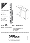
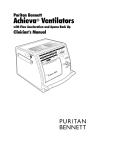
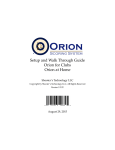
n° 51BL1802
Mod. ZF 420A
ZF 520A
EFFICIENCY
RULES
n° 51BL1801DR
Mod. Z 420A
Z 520A
n° 51BL1803DR
Mod. ZF 420A
ZF 520A
HIGH EFFICIENCY
n° 51BL1800
Mod. Z 420A
Z 520A
WALL-MOUNTED
COMBINATION BOILERS
CE
EXAMINATION
CERTIFICATES
SERIES
Mod. Z 420A – Z 520A – ZF 420A – ZF 520A
INSTRUCTIONS FOR:
USE AND MAINTENANCE.
INSTALLATION.
TO OBTAIN THE BEST PERFORMANCE FROM THE BOILER, PLEASE READ THESE INSTRUCTIONS CAREFULLY.
THIS BOOKLET MUST BE KEPT WITH THE COMBINATION BOILER SO THAT IT CAN BE CONSULTED BY THE USER AND QUALIFIED
PERSONNEL.
SARIgas Zoom Z – ZF
Page 1
Rev.0
USER INSTRUCTIONS
- Control panel, mod. Zoom Z 420A – Z 520A – ZF 420A – ZF 520A
Page 3
- Turning the boiler on and off mod. Zoom Z 420A – Z 520A – ZF 420A – ZF 520A
Page 4
- Useful tips for using the appliance
Page 5
- Maintenance
Page 5
- Changing gas
Page 5
- Ventilation in the room
Page 6
- Useful safety and installation tips
Page 6
- Working problems
Page 7
INSTALLATION INSTRUCTIONS
- Technical specifications
Page 8
- Installation procedures
Page 9
- Dimensions
Page 10
- Layout pre-assembly template fittings
Page 11
- Air intake-fume exhaust connection systems
Page 12
- Coaxial pipe connection example
Page 13
- Separate pipes connection example
Page 14
- Max. permitted lengths for the coaxial pipe
Page 15
- Max. permitted lengths for the separate pipes
Page 15
- Ventilation of the rooms boilers type B11BS – B22
Page. 16
- System piping
Page 17
- Gas and electric supply
Page 17
- Starting up – Before starting up the boiler
Page 18
- Bleeding the system – antifreeze precautions
Page 19
- Regulation with external control – connection diagram
Page 19
- Wiring diagram mod. Zoom Z 420A – Z 520A
Page 21
- Wiring diagram mod. Zoom ZF 420A – ZF 520A
Page 22
SARIgas Zoom Z – ZF
Page 2
Rev.0
USER INSTRUCTIONS
You have placed your trust in a firm specialised in heating and producing hot water for domestic use. This boiler has
been designed to respond to European standards. It has been manufactured with utmost care, conforming to current
safety standards.
Each appliance has been tested when working, and the inspector who carried out the tests has signed the warranty
certificate enclosed with the appliance documents.
In the case of problems, please return the warranty card (the original or a copy) to assist our research.
IMPORTANT:
- The boiler and document packaging material (foamed polystyrene, plastic bags) must be kept out of the
reach of children, as they are a potential source of danger.
- Children or the disabled must not use the appliance without supervision.
- Yearly maintenance must be carried out on the boiler together with a two-yearly check of the heating
system, controlling the safety components.
- The sealed components must not be interfered with or removed.
- Do not store chemical and/or inflammable substances in the room where the boiler is installed.
USE:
- Incorrect use of the boiler can cause breakdown or poor working of the appliance.
- If there is a smell of gas, do not touch the switches or any other electric appliances (telephone – intercoms
– electric fans - etc.).
Immediately open all the doors, windows and any other opening to grant rapid ventilation of the room.
Turn off the central gas outlet valve on the meter or the bottle valve. Immediately call a qualified
technician to check the problem.
BEFORE USING THE BOILER
-
The first start up of the boiler must be carried out by an authorised technician and the warranty certificate
must be correctly filled in.
-
Read these instructions carefully. By so doing, you will obtain the maximum performance from the boiler, saving
in energy too.
Control panel Zoom Z 420A – Z 520A – ZF 420A – ZF 520A
Fig.1
A – On/Off hot water selection switch
B – Summer/Winter heating setting selector switch
C – Heating water missing pilot light
D – Ready for working pilot light
SARIgas Zoom Z – ZF
E – Boiler reset pilot light button
F – Pressure gauge
G – Boiler thermometer
H – Programming clock (optional)
Page 3
Rev.1
STARTING UP THE BOILER
IGNITION OF THE MAIN BURNER (Fig. 1)
- Check that the water pressure to the system is 1 bar (pressure gauge F, Fig. 1). If the pressure is below 0.5 bar, fill
the boiler again (Fig.23/B).
- If the gas tap is installed, check it is open.
- Turn off the electric bipolar supply switch to the boiler, which is fitted on the outside of the appliance.
- Turn knob A to position I.
- The boiler is now ready to work normally. Main burner ignition is controlled by the boiler thermostat and/or the room
thermostat in the WINTER programme, or by drawing off running water, if required.
WORKING
Winter position HEATING PROGRAMME
- Turn knob B to the WINTER position (to the temperature you desire) and check that you can hear the circulation
pump working.
- If the system has a room thermostat fitted, it must be set to the maximum temperature.
- The burner fires automatically and the heating cycle starts up.
- Set the room thermostat to the desired temperature.
HOT WATER REQUIRED
- Turn on any hot water tap.
- When the requirements for hot water exceed 2.8
l./min., the boiler automatically goes into hot water
production.
- Turn the temperature setting knob A to the
temperature you think best.
The temperature of the hot water coming from
the boiler, depending on the drawn off water
capacity (with cold water intake at 59°F)
Summer position HOT WATER ONLY PROGRAMME
- Turn the knob B to the SUMMER programme .
- Turn on any hot water taps.
- When the requirements for running hot water exceed
2.8 l./min., the boiler automatically gets ready to
produce hot water.
- Turn the temperature setting knob A to the
temperature you think best
.
Fig.2
TURNING OFF
For short periods (12 – 24 hours)
- Turn the selector switch A to position 'O'.
For long winter periods
The Zoom series of boilers are fitted with an "automatic antifreeze protection system" in the heating and hot water
circuit, which triggers when temperatures fall below 3 – 5°C.
This function activates the pump and the gas burner (at minimum rated output), as long as the boiler is electrically
driven and the knob A, Fig, 1, is turned to "I". When a temperature of around 35°C is reached in the heating circuit, the
"antifreeze system" is automatically deactivated. It is good practice, however, to protect the heating circuit with a
suitable, specific chemical additive (antifreeze).
If the system is not protected with antifreeze, and the gas valves must be turned off upstream and the electrical supply
to the boiler turned off, empty the heating and the hot water circuits to avoid damage to the various components, the
heating system (pipes, radiators, etc.) and the hot and cold water supply pipes.
SARIgas Zoom Z – ZF
Page 4
Rev.0
USEFUL SUGGESTIONS FOR USING THE BOILER
Central heating
If a room thermostat has not been installed
- Set the boiler temperature on the basis of the room temperature.
If a room thermostat has been installed
- Set the boiler temperature (knob B, Fig. 1) between 50 - 80 °C
- Turn the room thermostat to the desired temperature
Water pressure in the system (see F Fig.1)
- Pressure, when cold, must not go below 0,7 bar.
- Pressure, when hot, must be not exceed 2 bar.
- Too frequent fillings, can be caused by boiler leaks. In this case, call out the installing firm.
N.B. If the system is subject to frequent emptying and, therefore, frequent filling, the water must be duly treated and
the "hardness" of the water, cause of lime scaling that damages the boiler, must be reduced to a minimum.
Producing hot water (see A Fig.1)
- If the main temperatures are kept at satisfactory levels, gas is saved and the life span of the specific
exchanger is extended, as the formation of lime is considerably reduced.
- Set the outlet hot water temperature directly on the boiler it isn’t advisable to reduce the water taking to low levels
because the burner could switch off or the temperature couldn’t keep the fixed valve.
- If the system has a "single command" type valve, the valve must be completely turned to the "hot" position, this
way the temperature of the outlet water is stabilised.
If the boiler locks-out repeatedly:
- If after a few attempts at unblocking the ignition device E Fig.1, the burner does not fire, it could be due to a fault or
due to a failure in the gas supply, call out the installing firm.
N.B. Do not insist in attempts at unblocking, unless at least 10 minutes have passed between one attempt and
another. The continuous outlet of gas during ignition can cause an elevated build up of gas in the combustion
chamber and therefore, when it lights up, an explosion. After repeated attempts, we recommend ventilating the
room by opening the doors and windows and immediately calling a qualified technician.
MAINTENANCE
External cleaning
- To clean the outside of the boiler, we advise using non-abrasive detergents.
- Do not use solvents or inflammable products.
- Use protective gloves for cleaning, against sharp or cutting edges.
- We advise cleaning only once the boiler has been turned off for at least 30 minutes, to avoid exposure to
overheated parts.
Boiler maintenance
- The minimum compulsory maintenance involves a yearly visit by a qualified technician who ascertains the correct
working of all the safety devices, and cleans the internal working parts, checks and sets if necessary.
- This yearly maintenance is prescribed and compulsory by Law, and guarantees the perfect working of the
appliance and constant high performance.
- Request the maintenance chart from an Authorised Service Centre.
Maintenance agreement
The yearly visit can be carried out on the basis of a subscription, which can cover spare parts, labour, consumption
material.
Fumes exhaust pipe
The fumes exhaust pipe must be controlled yearly (by a qualified technician) who checks the efficiency of the pipe
both for air-tightness and draft. He also inspects the ventilation grid in the boiler room.
GAS CHANGE
If the supply gas to the boiler is changed, certain changes must be made to inside parts of the boiler, and the gas
settings must be carried out again. Qualified and authorised technicians can only carry out these changes.
SARIgas Zoom Z – ZF
Page 5
Rev.0
VENTILATION OF THE ROOMS
VENTILATION OF THE ROOM IS COMPULSORY AND INDISPENSABLE FOR THE FOR SERIES
“Zoom” Z 420A Z 520A (Class B11BS appliances)
“Zoom” ZF 420A ZF 520A (Class B22 appliances) for installation see Page 14,15.
These boilers must be installed in suitable surroundings, which guarantee the correct level of air intake for
combustion; they must be connected to a flue gas evacuation circuit (flue pipe).
Adhere to local legislation regarding the ventilation required for the room.
Air vents on the outside walls of the where the boiler is installed:
-
Must have a free net air passage that conforms to current legislation in size;
Must be made in such a way that the inside and outside vents cannot be covered or blocked.
Must be protected with grids or wire net, etc., but the protection must not reduce the size of the passage as
indicated above.
- Correct aeration can be obtained from several vents, as long as the total net air passage corresponds to current
legislation.
- If the vents cannot be made near to the floor, the section of the vent opening must be increased, as indicated in
the specific standards.
- If there are other elements in the boiler room that draw in air to work, the section of the vent opening must be
adequately increased.
- If the boiler is installed in a room that contains a cooking hob without safety device, as it does not use an open
flame, the ventilation vents must be increased.
- The suction hood is always to be considered as an electric fan.
- An open fireplace must have its own air draft, otherwise gas appliances of the B11BS type cannot be installed in the
room.
If an external opening cannot be made, air flow from an adjacent room is allowed as long as the room is not in
negative pressure due to the presence of another draft (fireplace or stove) or another suction appliance, and it is not
used as a bedroom.
Zoom Z 420A – Z 520A boilers are fitted with a flue gas safety thermostat which, if there is poor draft in the flue
passes, permanently blocks the gas flow to the main burner .If the flue gas safety thermostat triggers, turn the boiler off
and immediately contact a qualified technician to test the boiler.
IMPORTANT: Under no circumstances must the flue gas safety thermostat be
blocked, interfered with or removed (see Fig. 3).
The opening must not be even partially blocked, to maintain adequate hygiene
and safety levels in the room; if the boiler room (Zoom Z 420A – Z 520A) is not
well ventilated, the main burner could halt frequently, triggering the flue gas
safety device of the boiler. If this happens, contact a qualified technician
immediately to carry out the necessary tests.
Fig.3
IMPORTANT
“B22” (ZF 420A; ZF 520A) boilers require suction of the combustion air directly from the room where they are installed.
Therefore, it is essential that the air suction grids, fig. 11 page 12, are never blocked for the boilers to work properly.
Do not close the boiler in hanging cupboards that are not sufficiently ventilated, and do not place other items on top of
the boiler.
Any electric, hydraulic and gas circuit parts must only be replaced with original SARIgas spare parts.
Only authorised and qualified SARIgas technicians must replace any faulty parts.
SARIgas declines all responsibility for damage caused by the improper use, faulty installation and the use of spare
parts that are not originals for the boiler.
SARIgas Zoom Z – ZF
Page 6
Rev.0
WORKING PROBLEMS
(For tests to be carried out inside the boiler contact the Authorised Service Centre).
THE BOILER DOES NOT WORK AND THE PILOT LIGHT "D", FIG. 2, IS TURNED OFF
Fault with the supply wire; contact the Authorised Service Centre.
If the supply wire is damaged, it must be replaced with a special wire that can be supplied by from the
Manufacturer or by an Authorised Service Centre.
THE BOILER WORKS INTERMITTENTLY AND THE PILOT LIGHT "D" FIG. 1, FLASHES ON AND OFF
-
The electronic circuit of the boiler automatically controls the correct working of some of the internal components,
and the high and low temperature alarms of the heating circuit, by flashing the pilot light "D" fig. 1, on and off. If this
light is flashing and the boiler works intermittently, wait at least 30 minutes, after which if the pilot light is still
flashing call the Authorised Service Centre to carry out the necessary checks.
THE MAIN BURNER DOES NOT FIRE FOR HEATING OR FOR PRODUCING HOT WATER
-
Knobs A and B Fig. 1, of the boiler are set too low.
The room thermostat (if fitted) is set too low.
The safety limit thermostat has triggered.
The manually rearmed flue gas safety limit thermostat has triggered (for models Zoom Z 420A - Z 520A).
Gas supply blocked, for all models (the E pilot light comes on, Fig. 1).
The ignition and flame control device is faulty (contact the Authorised Service Centre).
Water capacity too low (less than 2.8 l./min.).
Faulty electronic card (contact the Authorised Service Centre).
THE MAIN BURNER DOES NOT REMAIN ALIGHT
-
Poor gas supply in the pipes to the meter/boiler or low gas pressure to the burner.
The minimum gas pressure to the burner or ignition is too low.
The electric PHASE /NEUTRAL line is not correctly connected to the boiler (inverted) or the earth connection is
missing.
THE MAIN BURNER GOES OUT AFTER BEING ALIGHT FOR JUST A FEW MINUTES
(Just models Zoom Z 420A - Z 520A)
-
The fumes safety thermostat (Fig. 3) has triggered. Contact an Authorised Technician immediately to check the
boiler and/or the flue.
THE BOILER IS NOISY WHEN THE MAIN BURNER IS ALIGHT
-
Elevated gas pressure to the burner.
Water circulation to the heating system is too low.
Faulty circulator.
Exchanger scaled with lime.
Boiler valves (if fitted) are closed.
Electricity supply could be less than 195 V.
SMELL OF GAS
-
Turn off the main gas valve.
Open the doors and windows to aerate the room.
Do not turn on any switches or any other electrical appliance (telephone – intercom – electric fans – etc.).
Immediately call the Authorised Technician to carry out the necessary checks to the system.
SARIgas Zoom Z – ZF
Page 7
INSTALLATION
Rev.1
INSTRUCTIONS
IMPORTANT: The packing elements (foamed polystyrene, plastic bags) must be kept out of the reach of children, as
they are a potential source of danger.
This boiler has been designed to respond to European standards. It has been manufactured with greatest care, in compliance with
safety regulations. Each appliance has been tested when working, and the inspector who carried out the tests has signed the
warranty certificate enclosed with the appliance documents.
Check that the boiler supplied corresponds perfectly with its intended use.
-Indications of the type of boiler and gas to be used are given on the plate fitted behind the control panel, outside the boiler and on
the boiler packaging.
The products described in this manual have been correctly manufactured in conformity with current legislation.
The boilers are manufactured in accordance with EN specific safety Standards for fuel gas, as per Directive 90/396/CEE regarding
gas appliances and Directive 92/42/CEE regarding performance levels of new hot water boilers, that are driven by liquid or gas
fuels.
This appliance must be installed in accordance with the following Statutory Regulations and British Standards Codes of Practice:
Building Regulations (England and Wales). The Buildings Standards (Scotland) Regulations. Gas Safety (Installation and Use)
Regulations 1984. Current I.E.E. Wiring Regulations and Local Water Authority By-Laws.
Codes of practice: BS.6891 –Installation of low pressure gas pipework;
BS.6798 –Installation of gas fired hot water boilers of a rated input not exceeding 60 kW.
BS.5449:1 –Forced circulation hot water system (domestic central heating system smallbore and microbore).
nd
BS.5546 –Installation of gas hot water supplies for domestic purposes (2 family gases).
BS.5440:1 –Flues (for gas appliances of rated input not exceeding 60 kW).
BS.5440:2 –Air supply (for gas appliances of rated input not exceeding 60kW).
TECHNICAL SPECIFICATIONS
Btu / h - kW
Btu / h - kW
Btu / h - kW
Btu / h - kW
%
Working thermal efficiency at 30% of rated power (P.C.I.)
Lose of heat from casing (∆t 50°C)
Lose of heat through the chimney with the burner alight
Lose of heat through the chimney with the burner turned off
Max. working pressure of the heating circuit
Adjustable temperature in heating mode
Expansion tank – total volume
Rated heat throughput in sanitary mode (P.C.S.) D.H.W.
Reduced heat throughput in sanitary mode D.H.W.
Rated heat output in heating mode D.H.W.
Reduced heat output (working) in sanitary mode D.H.W.
Adjustable temperature in sanitary mode
Max. water available with continuous working (∆t 35°C)
Specific flow rate (EN 625)
Minimum sanitary water flow rate
Minimum / maximum D.H.W. sanitary water pressure
Electric connections
Rated absorption
Electric appliance protection
Maximum electricity consumption
CO2 content (methane) “B” type boilers
CO2 content (methane) “C” type boilers •••
CO2 content (LPG G30) “B-C” type boilers
Flue flow rate in weight (methane: G20)
Flue flow rate in weight (LPG: G30)
Fume temperature (methane: G20)
Fume flow rate in weight (LPG: G30)
Mod. Zoom
Z 420A – Z 520A
B11BS
Configuration
Rated heat throughput (P.C.S.)
Reduced heat throughput (P.C.S.)
Rated heat output working
Reduced heat output working
Working thermal efficiency at rated power (P.C.I.)
Energy efficiency
%
%
%
%
P.S.I. - bars
°F - °C
gals - litres
Btu / h - kW
Btu / h - kW
Btu / h - kW
Btu / h - kW
°F - °C
gals - litres/min
gals - litres/min
gals - litres/min
P.S.I. - bars
V / Hz
A
IP
W
% rated – reduced
% rated – reduced
% rated – reduced
g/s rated – reduced
g/s rated – reduced
°C rated – reduced
°C rated - reduced
97,490 – 28.6
47,275 – 13.86
80,000 – 23.45
36,845 – 10.8
90.2
87.4
2.5
5.8
0.8
42.67 - 3
86 / 176 - 30 / 80
1.32 / 1.54 - 6 / 7
97,570 – 28.6
36,504 – 10.7
80,000 – 23.45
31,727 – 9.3
95 / 131 - 35 / 55
2.13 – 9.6
2.51 - 11.3
0.62 – 2.8
0.02 / 1.55 - 0.1 / 7
230 / 50
0.5
X4 D
90
4.8 – 2.7
--------6 – 3.6
20.6 – 17.2
19 – 15
105 – 90
104 – 83
••• With coaxial pipe, max. length 3 metres.
SARIgas Zoom Z – ZF
Page 8
ZF 420A – ZF 520A
C12 C32 C42 C52 B22
97,490 – 28.6
48,745 – 14.3
80,170 – 23.49
38,210 – 11.2
90.4
88
2
6.5
1.1
42.67 - 3
86 / 176 - 30 / 80
1.32 / 1.54 - 6 / 7
97,570 – 28.6
36,504 – 10.7
80,716 – 23.62
31,727 – 9.3
95 / 131 - 35 / 55
2.13 – 9.6
2.51 - 11.3
0.62 - 2.8
0.02 / 1.55 - 0.1 / 7
230 / 50
0.8
X4 D
140
--------5.75 – 2.75
6.95 – 3.85
17.5 – 17.4
16.7 – 14.5
102 – 93
116 – 105
Rev.0
INSTALLATION REGULATIONS
- Installation must by carried out by a qualified technician in conformity with current legislation, local standards and with all due
dilegence.
- The boiler must not be installed in rooms used for storing inflammable substances (paper, rags, solvents, polystyrene, plastic,
etc.).
- Do not install the boiler in spaces where it is exposed to direct contact with cooking steam, in damp spaces, in rooms subject to
chemical vapours, such as laundries, hairdressers, etc.
POSITIONING THE BOILER
- This depends on the position of the fume exhaust duct fitting (fig. 4, 5 and 7) and it must be installed in a covered and
protected area, in accordance with local legislation.
FUME EXHAUST
- The flue pipe must be sized conforming to current legislation, and made of suitable materials.
- It is important that the first stretch of the pipe is vertical, with a length not less than 2 times the diameter of the flue pipe coming
from the boiler (for "B11BS" with natural draft).
- The connector pipe, from the boiler attachment to the flue pipe stack, must be of an adequate section, equal to that one of the
boiler connector. It must be adequately waterproofed.
- Installation must allow free expansion and dismantling of the materials.
- The stretch between the connector pipe and the flue pipe must be protected so that condensation water, which could form in the
flue pipe, cannot return to the boiler.
FUME EXHAUST FOR BOILERS WITH OPEN CHAMBER FORCED EXPULSION, TYPE "B22"
" B22" boilers work by taking the air to be burnt directly from the room where the boiler is installed, and connected in accordance
with the specifications on page 12, fig. 11.
FUME EXHAUST FOR BOILERS WITH SEALED CHAMBER FORCED EXPULSION, TYPE "C"
The "C" type boiler works by drawing the air to be burnt directly from the outside.
- Wall boilers with forced draft can be fitted with either the modular outlet system "COAXIAL FLUE" or with
"SEPARATE FLUES", see figs. 9-10 on page 12, and in accordance with the distances given in the tables on page
15.
In both cases, the flue gases can be expelled and the air drawn in either horizontally or vertically from the wall or
the roof, or through a double chamber flue pipe (only for versions with separate flues, configuration “C42”).
IMPORTANT:
It is ESSENTIAL to guarantee that the products of combustion coming from the flue pipe cannot return into the building or in any
other nearby room, through the ventilators, windows, doors, natural air infiltration or through forced ventilation air conditioning
systems.
POSITIONING THE FUME EXHAUST TERMINALS
FORCED FLOW SEALED CHAMBER APPLIANCES WITH CONFIGURATION TYPE C12-C52 B22
Terminal position
A
Below a window
600 mm
B
Below an air vent
600 mm
C
Below the gutter
300 mm
D
Below a balcony (1)
300 mm
E
From an adjacent window
400 mm
F
From an adjacent air vent
600 mm
G
From vertical or horizontal pipes or outlets (2)
300 mm
H
From a corner of a building
300 mm
I
From a recess in the building
300 mm
L
From the ground or another walkway
2500 mm
M
Between two terminals arranged vertically
1500 mm
N
O
Between two terminals arranged horizontally
From a front surface facing outwards without apertures or
terminals within a radius of 3 metres from the fume outlet
From a front surface facing outwards with apertures or
terminals within a radius of 3 metres from the fume outlet
1000 mm
2000 mm
P
Fig.4
3000 mm
NOTE
1)
2)
Terminals below a balcony must be positioned so that the total path of the fumes, from the point at switch they are emitted to the outlet on the
external perimeter of the balcony, is no less than 2000 mm.
The terminal must be positioned no less than 500 mm from materials sensitive to the action of the combustion products (for example, plastic
gutters or downspouts, wooden jetties etc.) unless these material are adequately screened.
Air supply for combustion and ventilation must be provided in accordance with BS.5440:2 regulations.
SARIgas Zoom Z – ZF
Page 9
Rev.0
DIMENSIONS
Mod. Zoom
Width
Height fittings centre distance
Depth
Stack Ø
Distance between stack axis-wall
Connection centre distance
Distance between gas fittings
/wall centre line
H Distance between water fittings /
wall centre line
A
B
C
D
E
F
G
Z 420A
ZF 420A
Z 520A
ZF 520A
in. - mm
in. - mm
in. - mm
in.- mm
in. - mm
in. - mm
in – mm
16.73 - 425
26.50 - 673
11.42 - 290
5.12 - 130
6.77 - 172
14.60 - 371
4.80 - 122
16.73 - 425
26.50 - 673
11.42 - 290
3.94 - 100
7.91 - 201
14.60 - 371
4.80 - 122
19.68 - 500
26.50 - 673
9.05 - 230
5.12 - 130
4.37 - 111
15.43 - 392
2.40 - 61
19.68 - 500
26.50 - 673
9.05 - 230
3.94 - 100
5.51 - 140
15.43 - 392
2.40 - 61
in. - mm
5.04 - 128
5.04 - 128
2.64 - 67
2.64 - 67
NATURAL DRAUGHT BOILER (Mod. Z 420A - Z 520A)
B 11BS boilers that draw the air directly from the room where they are installed.
OPEN CHAMBER FORCED DRAUGHT BOILER configuration B22 (Mod. ZF 420A - ZF 520A).
Boilers that work by drawing the air directly from the room where they are installed.
For the length of the flue pipes, follow the instructions given in the table on page 15 and figures 11-17.
ATTENTION: Permanent ventilation is required for the boiler room, in accordance with current laws.
Z 420A
Z 520A
Fig. 5
KEY
PREASSEMBLY TEMPLATE FITTINGS LAYOUT (optional)
HD - Heating delivery Ø ¾”
SWO - Sanitary water outlet Ø ½”
HR - Heating return Ø ¾”
SWI - Sanitary water inlet Ø ½”
SV - Safety valve 3 bars (42.67 P.S.I.)
Fig. 6
SARIgas Zoom Z – ZF
Page 10
FORCED DRAUGHT BOILERS (Mod. Zoom ZF 420A - ZF 520A)
Boilers for C12 - C32 – C42 - C52 type configuration taking the air directly from the outside.
For C42 configuration, refer to EN 483 standards, Chapter 8.2.1.4. paragraph "I".
ATTENTION: Ventilation of the room in accordance with current laws.
Boiler with coaxial flue pipe
Boiler with separate flue pipes
Wall
ZF 420A
ZF 420A
Wall
ZF 520A
ZF 520A
Fig. 7
Layout of fittings
KEY
1)
2)
3)
4)
5)
6)
(HR) Heating return
(SWI) Sanitary water inlet
(GAS) Gas inlet
(SWO) Sanitary water outlet
(HD) Heating delivery
(SV) Safety valve 3 bars (42,67 P.C.I.)
Fig. 8
SARIgas Zoom Z – ZF
Page 11
Rev.0
Rev.1
AIR SUCTION / FLUE DISCHARGE CONNECTION SYSTEMS
SUCTION AND DISCHARGE COAXIAL SYSTEM
If horizontal coaxial pipes are chosen, the boiler must be fitted with a coaxial curved connector (1) Fig. 9, with vertical
coaxial pipes, must be fitted Fig. 9 connector (2).
SUCTION AND DISCHARGE WITH SEPARATE FLUE SYSTEMS configuration C12 C32 C42 C52
Air suction and flue discharge can be effected through two separate pipes; in this case, the boiler must be fitted with a
special connector for both suction and discharge. For this version too, a vertical or horizontal wall/roof terminal can be
fitted by using the relative connectors (3) Fig. 10.
SYSTEM WITH JUST THE FLUE EXPULSION PIPE configuration B22
Air is drawn in directly from the boiler room.
The suction connector (3) must be fitted with a protection net as given in Fig. 11.
N.B. the suction / discharge connection systems must not exceed the maximum lengths allowed and specified
in the instructions (tables A.B.C. page 15).
Fig.9
Fig.10
Coaxial pipe
Separate pipes
Fig.11
Fumes exhaust pipe duet
3) Suction / discharge collector kit ∅80 3) Suction / discharge collector kit ∅80
mm for separate pipes, complete with
mm. for separate pipes complete with
gaskets (Art.01156)
gaskets (Art.01156)
Or:
4) Protection net (Art.0239)
suction / discharge adapter kit
∅80/100 mm for separate pipes,
Flue gases outlet ∅ 60 mm.
complete with gaskets (Art.01184).
A. Drawing off point for combustion
Air suction ∅ 100 mm.
products and combustible air.
A. Drawing off point for combustion A. Drawing off point for combustion D. Air diaphragm ∅ 46 mm. to fit into
the end of the ventilator as per Table
products and combustible air.
products and combustible air.
“B” page 15.
D.
Air
diaphragm
∅
46
mm
to
fit
into
D. Air diaphragm ∅ 46 mm to fit into
the
end
of
the
ventilator
as
per
Tables
the end of the ventilator as per table
“B - C” page 15.
“A” page 15.
1) Elbow coaxial connector
(Art.00419)
2) Straight coaxial connector
(Art.00742)
SARIgas Zoom Z – ZF
Page 12
Rev.1
CONNECTION EXAMPLES FOR COAXIAL PIPES FOR TYPE "C" BOILERS (with pipes ∅60/100 mm)
This solution allows a max. length of the flue pipes of 3 metres for the horizontal pipe and 4 metres for the vertical pipe. Each
extra 90° connector that is fitted reduces by 1 metre the max. extension of the piping.
Fig.12
C 12
Horizontal outlet with elbow connector and extension pipe
Fig.13
C 12
Horizontal outlet with straight connection and extension pipe
Fig.14
C 32
Vertical outlet with extension pipes
Fig.15
C 32
Vertical outlet with elbow connector and extension pipes
SARIgas Zoom Z – ZF
Page 13
Rev.4
CONNECTION EXAMPLES OF SEPARATE PIPES FOR TYPE "C" BOILERS (with piping of ∅80 mm)
This solution allows a max. length of the flue expulsion pipes plus air suction of 30 metres.
The air suction pipe however, must not exceed 10 metres in length. In case of distances exceeding 10 metres (20 metres for the
pipe ∅100mm) remove the drawing on the intake hole of the comburent air (Fig.11 Ref. 5).
Fig.16
C 32
Vertical outlet with elbow connector and extension pipes
Fig.17
(The pipes cannot be fitted onto opposite walls)
B22
C52
If the B22 configuration boiler is installed, part
Art.00239 must be fitted to the air suction pipe
(Art.01156).
.
Fig.19
C 42
Horizontal/Vertical flue outlet with elbow connectors and extension pipes
For the C42 configuration refer to EN 483 Standard, Chapter 8.2.1.4.,
paragraph "I".
SARIgas Zoom Z – ZF
Page 14
Wall outlets with elbow
connectors, extension pipes and
separate terminals.
Rev.2
MAXIMUM LENGTHS ALLOWED FOR THE PIPING WITH "COAXIAL" AIR INTAKE EXHAUST
FUME SYSTEMS C12 C32 C42
The maximum length of the piping for the straight coaxial pipe is 3 metres for the horizontal pipe and 4 metres for the
vertical version.
With length less than 0.7 metre., a diaphragm of ∅ 46 mm must be fitted into the opening of the ventilator, which is
supplied by us (see Figs. 9-10-11 page 12.).
Coaxial exhaust flue pipes diameter 60/100 mm
Minimum length
Maximum length
With diaphragm ∅ 46 mm
0,2 m
0,7m
Without diaphragm
0,7 m
4 m (vertical)
Table “A”
MAXIMUM LENGTHS ALLOWED FOR PIPING WITH "SEPARATE" AIR INTAKE EXHAUST
SYSTEMS C12 C32 C42 C52 B22
-
The maximum length of the piping is obtained by adding the flue expulsion pipe to the length of the air suction pipe.
The sum of the two lengths must not exceed 30 metres, each direction change reduces the available length in the
pipes by the following ratio:
For 45° angles, reduction is 0.5 metre per unit (for ∅ 80 mm pipes).
For 90° angles, reduction is 1 metre per unit (for ∅ 80 mm pipes).
Separate exhaust flue pipes, diameter 80 mm C12 C32 C42 C52
Table “B”
With ∅ 46 mm. diaphragm
Without diaphragm
Minimum length
Maximum length
0,2 m +0,2 m
5m+5m
5m+5m
10 m + 20 m
Only exhaust flue pipe, diameter 80 mm B22
Maximum length
With ∅ 46 mm. diaphragm
16 m
Without diaphragm
23 m
Separate exhaust flue pipes, diameter 100 mm C12 C32 C42 C52
Table “C”
Without diaphragm
N.B.
Minimum length
Maximum length
(above 30 m)
20 m + 70 m
: the air suction pipe cannot exceed a maximum distance of 10 metres per pipe ∅ 80 mm and 20 metres for
pipes of ∅ 100 mm. In case of distances exceeding 10 metres (20 metres for the pipe ∅100mm) remove the
drawing on the intake hole of the comburent air (Fig.11 Ref. 5).
For a 45° bend, reduction is 0.5 metre per unit (for ∅ 100 mm pipes).
For a 90° bend, reduction is 1 metre per unit ( for ∅ 100 mm. pipes).
- The maximum lengths for the flue pipes refer to material supplied by us.
- SARIgas declines all responsibility for poor working of the boiler, damage to people and things caused by the use of
material not supplied by us.
- The condensation limit at 32°F is 5 metres. (flue outlet pipe length).
IMPORTANT: if necessary, insulate the flue outlet pipe to avoid temperature drop of the fumes along the pipes. Max.
drop allowed per metre of pipe must be less than 34°F.
SARIgas Zoom Z – ZF
Page 15
Rev.0
ROOM VENTILATION FOR NATURAL DRAUGHT BOILERS, TYPE “B11BS ” mod. Z 420A - Z 520A
mod. ZF 420A ZF 520A (Class B22 appliances) for installation refer to pages 14,15.
These boilers must be installed in suitable environments, which guarantee the right level of combustible air
intake; they must be connected to a exhaust flue outlet pipe.
For ventilation, refer to local legislation.
B11BS Boilers are the open chamber type, designed for connecting to exhaust pipe for the combustion products to the
outside of the room: combustible air is taken directly from the room where the boiler is installed.
Air vents on the outside walls of the boiler room:
- Must have a free net air passage that conforms to current legislation in size;
- Must be made in such a way that the inside and outside vents cannot be covered or blocked.
- Must be protected with grids or wire net, etc., but the protection must not reduce the size of the passage as indicated
above.
- Correct aeration can be obtained from several vents, as long as the total net air passage corresponds to current
legislation.
- If the vents cannot be made near to the floor, the section of the vent opening must be increased, as indicated in the
specific standards.
- If there are other elements in the boiler room that draw in air to work, the section of the vent opening must be
adequately increased.
- If the boiler is installed in a room that contains a cooking hob without safety device, as it does not use an open flame,
the ventilation vents must be increased.
- The suction hood is always to be considered as an electric fan.
- An open fireplace must have its own air draft, otherwise gas appliances of the B11BS type cannot be installed in the
room.
If an external opening cannot be made, air flow from an adjacent room is allowed as long as the room is not in
negative pressure due to the presence of another draft (fireplace or stove) or another suction appliance, and it is not
used as a bedroom.
Zoom Z 420A – Z 520A boilers are fitted with a manual reset flue gas safety thermostat which, if there is poor draft in
the flue pipe, permanently blocks the gas flow to the main burner. Therefore before beginning installation check the
working features (flue pipe draft, "flue"), the sizes, such as the ∅ of the flue opening, and the inside section which must
be adequate to support the output of the boiler.
If the flue safety thermostat triggers while the boiler is working, turn off the boiler and the electric supply to the
boiler, remove the blocking clamp of the electric plug connected to the thermostat (Fig. 20), press the red thermostat
rearm button with your finger. Reconnect the previously removed plug, replace the previously removed clamp and carry
out a new flue draft test.
IMPORTANT: Under no circumstances must the flue safety thermostat be blocked, interfered with or removed from its
original position (see Fig.20).
ATTENTION:
To ventilate the rooms fitted with mod. ZF 420A, ZF 520A
boilers, with configuration B22, refer to the specific
Standards for "B" type appliances.
Follow the instructions given on pages 14-15 to install the
flue pipes.
Fig.20
SARIgas Zoom Z – ZF
Page 16
HEATING ALTERNATIVELY, A FUSED DOBLLE POLE PIPING SYSTEM
Rev.0
- The section of the piping depends on the methods currently used, using the curve given in the diagram (Figs. 21-22).
We recommend using a capacity that keeps the temperature difference between delivery and return from the heating
system between 41°F and 50°F.
Available head and capacities for heating systems at
the boiler fittings
Diagram of pressure drops of the sanitary water
circuit to the boiler fittings
Fig.21
Fig.22
HEATING ELEMENTS
- Radiators, convectors or fancoil heaters can all be used.
- The maximum temperature of the boiler grants calculating the exchange surface for a temperature of 176°F.
however we recommend calculating the exchange area by taking a lower temperature as reference value, thus
allowing to improve comfort and reduce energy consumption.
- The radiators must be fitted with adjustable input connectors, which allow balancing the system, and manual
bleeders on the top points.
CONNECTING THE GAS PIPES
The section of the pipes, between the metre and the boiler, must be of a size to reach the supply pressure given on
the label. It must be possible to close the piping if the boiler is dismantled, by fixing an interception valve between the
boiler and the gas pipe. For installation and the materials to be used, refer to local legislation. Ensure that the boiler is
compatible with the gas supplied.
ELECTRICITY SUPPLY
The electric supply wire to the boiler must be fuse the supply at 3 A unswitched schuttered socket outlet to the
requirements of BS 1363 switch, which guarantees complete disconnection of the supply, with contacts having an
opening of at least 1/8 in. Connect to a power supply of 230 Volt 50 Hz, respecting the phase "L" and neutral "N".
Consult the relative wiring diagram on page 19, Fig. 25.
- The earth wire must be connected to the earth terminal marked by the symbol
.
A multiple PVC wire type H05 VV-F or H05 VVH2-F, must be used for the electricity supply wire, with a section of 3 x
2
0,75 mm , and the earth wire to the boiler must be longer than the supply wires.
N.B. If the correct polarity is not respected, the boiler will halt and the block alarm will come on (lighted button E, Fig.
1). If there is minimum electric voltage (5 -10 V), between Neutral and Earth the boiler will not work correctly.
SARIgas Zoom Z – ZF
Page 17
Rev.0
START UP
WARNINGS BEFORE STARTING UP
Important:
Before filling the system, check that the pump is not blocked.
- If the pump is blocked, remove the protective cap and use a screwdriver to rotate the pump rotor pin to the right
and left (Fig. 23/A).
- With the gas valve closed, check that the metre does not record the passage of gas for at least 10 minutes.
- Check that all the bleed valves on the system are open.
- Open the filling valve (Fig. 23/B) until the pressure given on the pressure gauge F, Fig. 1, indicates at least 1 bar
(14.22 P.S.I.).
- Close all the bleed valves in the system as soon as water starts to come out.
- At the end, close the filling valve when the pressure given on the pressure gauge is above 1.2 bar (max.1.5 bar)
17P.S.I. (max..21.33 P.S.I.): knob A Fig. 1, must be in position "O" to carry out this operation.
- Any future bleeding should be done with knob A in position "O".
Bleeding the boiler
Before filling the system with water, loosen the plastic cap of the automatic bleeding valve to remove the air
contained inside the boiler and heat exchanger.
Do not force manually the automatic valve outlet, as the water that comes out deposits micro particles of dirt on the
housing of the seal, and therefore dripping is unavoidable.
When the boiler is working, the bleeding valve cap must always be loose.
BEFORE STARTING UP THE BOILER
Carry out the following sequence, referring to figures 1-23:
1) If the gas valve is fitted to the boiler, turn it off.
2) Open the inlet cold water valve (if fitted).
3) Correctly fill the central heating system with water (see Fig. 23/B) and check that the pressure gauge (F fig. 1)
gives a pressure of at least 1.2 bar (17 P.S.I.). No water must flow out from the safety valve evacuation hole (fig. 8,
ref. 6).
4) Carry out the wiring connections to the boiler to 230 Volt - 50 Hz, according to the wiring diagrams on page 19,
Fig. 25. Wiring schould be in 3 core PVC cable not less than 0,75 mm to BS 6500 table 16, wiring external to the
boiler must be in accordance with the current I.E.E. wiring regulations and any local regulations which apply
5) Before opening the gas valve tap, the pump must be turned for a few minutes, by turning knob A to "I" and
knob B to WINTER , after about ten minutes open the gas valve tap, press button E Fig. 1, to start up the cycle.
Zoom
Fig. 23/A
Fig. 23/B
SARIgas Zoom Z – ZF
Page 18
Rev.1
BLEEDING THE SYSTEM
If the air has not been completely bled from the system, the boiler will not work correctly. When the boiler has been
working in heating mode a few hours, bleed the system again as given on page 18.
If necessary, the system can be topped up with water.
PRECAUTIONS AGAINST FREEZING (house empty in the winter)
For short periods (12 – 24 hours)
- Turn the selector switch A to 'O'.
For long winter periods
The Zoom series of boilers are fitted with an "automatic antifreeze protection system" in the heating and hot water
circuit, which triggers when temperatures fall below 3 – 5°C.
This function activates the pump and the gas burner (at minimum rated output), as long as the boiler is electrically
driven and the knob A, Fig, 1, is turned to "I". When a temperature of around 35°C is reached in the heating circuit, the
"antifreeze system" is automatically deactivated. It is good practice, however, to protect the heating circuit with a
suitable, specific chemical additive (antifreeze) in a maximum proportion of 30% of the total water volume.
If the system is not protected with antifreeze, and the gas valves must be turned off upstream and the electrical supply
to the boiler turned off, empty the heating and the hot water circuits.
REGULATION WITH EXTERNAL CONTROL (optional)
The combination boiler can be controlled by an external regulation composed by:
- Remote Control; (code – set remote control 20572)
The remote control permits the control and the regulation of the combination boiler and the faults signalling (led).
The maximum distance between the combination boiler and the remote control must be 300 metres (Fig.26).
The remote control must be linked to the combination boiler using an independent electric pipe without cables under
voltage.
The remote control is easy to install and to use and it permits to the user to check the operating faults through the
luminous leds.
There are also other leds that permits to check the consumption of the boiler in real time. It’s also possible to link an
ambient thermostat to the remote control (see instructions below Fig.27 and 28).
- Ambient thermostat; It’s advisable to choose an high quality thermostat (with low differential). This ambient
thermostat must be linked to the connectors C and D of the regulation circuit (Fig.24). The electrical connection
must be cut off using a cable composed by two wires (in conformity with the local rules).
- Time clock; The time clock can be installed directly in the combination boiler using the set of components supplied
by SARIgas in order to make the installation easier. The time clock must be linked to the wires C and D after having
removed the existing electrical connection (Fig.29).
Warning: The wrong connection of the circuit “R1” with the circuit “M2” electrically connected, can cause
permanent damages on both circuits. Before connecting the electrical connection it is advisable
to verify visually the right position of both connectors.
WARNING: Before making the connections it’s necessary to disconnect the power supply.
WIRING DIAGRAM TO THE ROOM THERMOSTAT
WARNING:
WIRING DIAGRAM TO THE POWER SUPPLY
Fig.24
In this king of connection, the existing connection wire
must be cut off from the connector C-D of the circuit M2.
SARIgas Zoom Z – ZF
Fig.25
WARNING:
The connecting wire to the C-D terminal must not be powered,
and must be connected to a "clean" On-Off contact.
Faulty connection of the C-D terminal: if the electric wire is
powered at 230 volt the adjustment card will burn out and
consequently cancel the guarantee terms.
Page 19
WARNING: Before making the connections it’s necessary to disconnect the power supply.
CONNECTION TO THE REGULATION CIRCUIT “M2”
WITH REMOTE CONTROL (OPTIONAL) Cod.20572
WARNING:
Fig.26
In this type of connection, the connectors C-D must be linked
to the regulation circuit M2 and the connector C1-D1 of the
regulation circuit R2.
Warning: Connect and disconnect the circuit “R1” only after
having removed the existing electrical connection of
the combi boiler.
CONNECTION TO THE REGULATION CIRCUIT “M2”
WITH REMOTE CONTROL AND AMBIENT
THERMOSTAT (linked to the connector C1-D1 of the
regulation circuit ”R2”)
WARNING:
Fig.28
In this type of connection, the connector C-D of the regulation
circuit “M2” must be linked.
Warning: Connect and disconnect the circuit “R1” only after
having removed the existing electrical connection of
the combi boiler.
SARIgas Zoom Z – ZF
Rev.1
CONNECTION TO THE REGULATION CIRCUIT “M2”
WITH REMOTE CONTROL AND AMBIENT
THERMOSTAT (linked to the connector C-D of the
regulation cicuit “M2”)
WARNING:
Fig.27
In this type of connection, the connector C1-D1 of the
regulation circuit R2 must be linked.
Warning: Connect and disconnect the circuit “R1” only after
having removed the existing electrical connection
of the combi boiler.
CONNECTION TO THE REGULATION CIRCUIT “M2”
WITH DAILY TIME CLOCK Cod.20573
WARNING:
Fig.29
In this king of connection the cables of the time clock (M1M2) must be linked to the power supply of the circuit (L-N),
as indicated in the drawing.
Page 20
Rev.2
INTERNAL WIRING DIAGRAM FOR NATURAL DRAUGHT AUTOMATIC IGNITION BOILERS,
SERIES Zoom Z 420A – Z 520A
Signals on the "P.C.B." card
A.
B.
E.
•
•
F.
•
G.
•
S.W.F.D. – Sanitary flow detector
S.T.P. – Sanitary temperature probe
H.T.P. – Heating temperature probe
S.T.
– Safety thermostat
M.R.L.T. – Manual reset limit thermostat
I.R.B. – Luminous reset button
R.O.L. – Ready for operation light
C.P.
– Circulation pump
KEY:
SARIgas Zoom Z – ZF
Gas valve opening consent
Heating pump activation
Led permanently “ON”: exchanger
temperature > 90°C
Led flashing (ON/OFF). Warning threshold
for antifreeze pump activation
Led brief flashing (ON/OFF):
Warning threshold for antifreeze pump and
gas valve activation.
Led permanently “ON”:
Hot water programme active.
Led flashing (ON/OFF):
Fault for the sanitary water probe.
Led permanently “ON”:
heating programme active.
Led flashing (ON/OFF):
Fault for the heating system probe.
W.S.P.S. – Water safety pressure switch
W.S.L. – No water signalling light
I.E.
– Ignition electrode
D.E.
– Detector electrode
I.C.U.
– Ignition control unit
P.C.B. – Printed circuit board (Cod.01131)
R.L.
– Remote light no ignition (max 3 mA)
Page 21
Rev.2
INTERNAL WIRING DIAGRAM FOR FORCED DRAUGHT AUTOMATIC IGNITION BOILERS,
SERIES Zoom ZF 420A – ZF 520A
Signals on the "P.C.B." card
A.
B.
E.
•
•
F.
•
G.
•
S.W.F.D. – Sanitary flow detector
S.T.P. – Sanitary temperature probe
H.T.P. – Heating temperature probe
S.T.
– Safety thermostat
F.S.P.S. – Fan safety pressure switch
F.
– Fan
I.R.B. – Illuminated reset button
R.O.L. – Ready for operation light
KEY:
SARIgas Zoom Z – ZF
Gas valve opening consent
Heating pump activation
Led permanently “ON”: exchanger
temperature > 90°C
Led flashing (ON/OFF). Warning threshold
for antifreeze pump activation
Led brief flashing (ON/OFF):
Warning threshold for antifreeze pump and
gas valve activation.
Led permanently “ON”:
Hot water programme active.
Led flashing (ON/OFF):
Fault for the sanitary water probe.
Led permanently “ON”:
heating programme active.
Led flashing (ON/OFF):
Fault for the heating system probe.
C.P.
– Circulation pump
W.S.P.S. – Water safety pressure switch
W.S.L. – No water signalling light
I.E.
– Ignition electrode
D.E.
– Detector electrode
I.C.U.
– Ignition control unit
P.C.B. – Printed circuit board (Cod.01131)
R.L.
– Remote light no ignition (max 3 mA)
Page 22
Rev.0
NOTE
____________________________________________________
____________________________________________________
____________________________________________________
____________________________________________________
____________________________________________________
____________________________________________________
____________________________________________________
____________________________________________________
____________________________________________________
____________________________________________________
____________________________________________________
____________________________________________________
____________________________________________________
____________________________________________________
____________________________________________________
____________________________________________________
____________________________________________________
____________________________________________________
____________________________________________________
____________________________________________________
____________________________________________________
____________________________________________________
____________________________________________________
____________________________________________________
____________________________________________________
____________________________________________________
____________________________________________________
____________________________________________________
SARIgas Zoom Z – ZF
Page 23
02-05 Cod.01253
Authorized Servicing Centre
Via Olanda, 1 – 37069 Villafranca di Verona (VR)– Italia – Tel – 045/8520650 – Fax – 045/8520761
www.sarigas.it E-Mail: [email protected]
SARIgas Zoom Z – ZF
Page 24