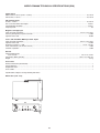
1
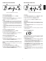
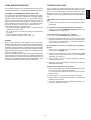
Model PM4400 User Guide INTEGRATED AMPLIFIER ITALIANO ENGLISH WARRANTY GARANZIA For warranty information, contact your local Marantz distributor. RETAIN YOUR PURCHASE RECEIPT Your purchase receipt is your permanent record of a valuable purchase. It should be kept in a safe place to be referred to as necessary for insurance purposes or when corresponding with Marantz. L’apparecchio è coperto da una garanzia di buon funzionamento della durata di un anno, o del periodo previsto dalla legge, a partire dalla data di acquisto comprovata da un documento attestante il nominativo del Rivenditore e la data di vendita. La garanzia sarà prestata con la sostituzione o la riparazione gratuita delle parti difettose. Non sono coperti da garanzia difetti derivanti da uso improprio, errata installazione, manutenzione effettuata da personale non autorizzato o, comunque, da circostanze che non possano riferirsi a difetti di funzionamento dell’apparecchio. Sono inoltre esclusi dalla garanzia gli interventi inerenti l’installazione e l’allacciamento agli impianti di alimentazione. Gli apparecchi verranno riparati presso i nostri Centri di Assistenza Autorizzati. Le spese ed i rischi di trasporto sono a carico del cliente. La casa costruttrice declina ogni responsabilità per danni diretti o indiretti provocati dalla inosservanza delle prescrizioni di installazione, uso e manutenzione dettagliate nel presente manuale o per guasti dovuti ad uso continuato a fini professionali. IMPORTANT When seeking warranty service, it is the responsibility of the consumer to establish proof and date of purchase. Your purchase receipt or invoice is adequate for such proof. FOR U.K. ONLY This undertaking is in addition to a consumer's statutory rights and does not affect those rights in any way. FRANÇAIS GARANTIE PORTUGUÊS Pour des informations sur la garantie, contacter le distributeur local Marantz. CONSERVER L'ATTESTATION D'ACHAT GARANTIA L'attestation d'achat est la preuve permanente d'un achat de valeur. La conserver en lieu sur pour s'y reporter aux fins d'obtention d'une couverture d'assurance ou dans le cadre de correspondances avec Marantz. Para informações sobre a garantia, contactar o distribuidor Marantz local. GUARDAR O RECIBO DE COMPRA O recibo é o registo permanente da compra que fez. Deve ser guardado num local seguro, para ser apresentado em questões relacionadas com o seguro ou para quando tiver de contactar a Marantz. IMPORTANT Pour l'obtention d'un service couvert par la garantie, il incombe au client d'établir la preuve de l'achat et d'en corroborer la date. Le reçu ou la facture constituent des preuves suffisantes. IMPORTANTE Quando procurar assisténcia técnica ao abrigo da garantia, é da responsabilidade do consumidor estabelecer a prova e data de compra. O recibe é prova adequada. DEUTSCH ESPAÑOL GARANTIE Bei Garantiefragen wenden Sie sich bitte an Ihren Marantz-Händler. GARANTIA HEBEN SIE IHRE QUITTING GUT AUF Para obtener información acerca de la garantia póngase en contacto con su distribuidor Marantz. Die Quittung dient Ihnen als bleibende Unterlage für Ihren wertvollen Einkauf Das Aufbewahren der Quittung ist wichtig, da die darin enthaltenen Angaben für Versicherungswecke oder bei Korrespondenz mit Marantz angeführt werden müssen. GUARDE SU RECIBO DE COMPRA Su recibo de compra es su prueba permanente de haber adquirido un aparato de valor, Este recibo deberá guardarlo en un lugar seguro y utilizarlo como referencia cuando tenga que hacer uso del seguro o se ponga en contacto con Marantz. WICHTIG! Bei Garantiefragen muß der Kunde eine Kaufunterlage mit Kaufdatum vorlegen. Ihren Quittung oder Rechnung ist als Unterlage ausreichend. IMPORTANTE Cuando solicite el servicio otorgado por la garantia el usuario tiene la responsabilidad de demonstrar cuá¥do efectuó la compra. En este caso, su recibo de compra será la prueba apropiada. NEDERLANDS GARANTIE SVENSKA Voor inlichtingen omtrent garantie dient u zich tot uw plaatselijke Marantz. UW KWITANTIE, KASSABON E.D. BEWAREN GARANTI Uw kwitantie, kassabon e.d. vormen uw bewijs van aankoop van een waardevol artikel en dienen op een veilige plaats bewaard te worden voor evt, verwijzing bijv, in verbend met verzekering of bij correspondentie met Marantz. För information om garantin, kontakta Marantz lokalagent. SPAR KVITTOT Kvittot är ett inköpsbevis på en värdefull vara. Det skall förvaras säkert och hänvisas till vid försäkringsfall eller vidkorrespondens mod Marantz. BELANGRIJK Bij een evt, beroep op de garantie is het de verantwoordelijkheid van de consument een gedateerd bewijs van aankoop te tonen. Uw kassabon of factuurzijn voldoende bewijs. VIKTIGT Fö att garantin skall gälla är det kundens sak att framställa bevis och datum om köpet. Kvitto eller faktura är tillräokligt bevis fö detta. DANSK GARANTI Henvend dem til Deres MARANTZ-forhandler angående inrformation om garantien. GEM DERES KVITTERING Deres købskvittering er Deres varige bevis på et dyrt køb. Den bør gemmes godt og anvendes som bevis, hvis De vil tegne en forsikring, eller hvis De kommunikerer med Marantz. VIGTIGT Det påhviler forbrugeren at skaffe bevis for købet og købsdatoen, hvis han eller hun ønsker garantiservice. Deres købskvittering eller faktura er et fuldgyldigt bevis herpå. 1 CONTENTS LIST English .................................................................................................................................... page 4 Français .................................................................................................................................. page 9 Deutsch ................................................................................................................................. Seite 14 Nederlands ..........................................................................................................................pagina 19 Italiano .................................................................................................................................pagina 24 Português ............................................................................................................................página 29 Español ...............................................................................................................................página 34 Svenska ................................................................................................................................ sidan 39 Dansk .................................................................................................................................... page 44 Specifications ........................................................................................................................ page 49 Figures .................................................................................................................................. page 50 CE MARKING English This PM4400 is in conformity with EMC directive and low-voltage directive. Français Le PM4400 est conforme à la directive EMC et à la directive sur les basses tensions. Deutsch Das Modell PM4400 entspricht den EMC-Richtlinien und den Richtlinien für Niederspannungsgeräqte. Nederlands De PM4400 voldoet ann de EMC-eisen en de vereisten voor laagspanning. Italiano Il PM4400 è conforme alle diettive CEE ed a quelle per i bassi voltaggi. Português O PM4400 conforma com as diretrizes EMC e de baixa voltagem. Español El PM4400 está de acuerdo con las normas EMC y las relacionadas con baja tensión. Svenska PM4400 tillverkad i enlighe med EMC direktiven och direktiven för låvoltsutrusing. Dansk Model PM4400 er i overensstemmelse med EMC-direktiveet og direktivet om lavspænding. 2 English To ventilate the unit, do not install the unit in a rack or bookshelf, and note the followings. - Do not touch the top of the enclosure during operation. - Do not block the openings in the enclosure during operation. - Do not insert objects beneath the unit. - Do not block the ventilation slots at the top of the unit. Do not place anything about 1 meter above the top panel. - Make a space of about 0.2 meter around the unit. Italiano Perch é l'unità possa essere sempre ben ventilata, non installarla in scaffali o librerie e tenere presente quanto segue. - Non toccare la parte superiore del rivestimento durante il funzionamento. - Non bloccare le aperture sul rivestimento durante il funzionamento. - Non inserire oggetti al di sotto dell'unità. - Non bloccare le fessure di ventilazione sopra l'unità. Non posare nulla per circa un metro sopra il pannello superiore. - Lasciare 0,2 metro liberi tutto intorno l'unità. Français Pour que l'appareil puisse être correctement ventilé, ne pas l'installer dans un meuble ou une bibliothèque et respecter ce qui suit. - Ne pas toucher le dessus du coffret. - Ne pas obstruer les ouïes de ventilation du coffret pendant le fonctionnement. - Ne placer aucun objet sous l'appareil. - Ne pas obstruer les ouães de ventilation du panneau supérieur. Ne placer aucun objet à moins d'un mètre environ du panneau supérieur. - Veiller à ce qu'aucun objet ne soit à moins de 0,2 mètre des côtés de l'appareil. Português Para ventilar o aparelho, não instalá-lo dentro duma estante ou algo similar, e observar as seguintes recomendações: - Não tocar a parte superior do aparelho durante a operação. - Não bloquear as aberturas do aparelho durante a operação. - Não insertar objectos debaixo do aparelho. - Não bloquear as aberturas de ventilação na parte de cima do aparelho. Deixar um espaço completamente livre de cerca de 1 metro acima do painel superior. - Deixar um espaço de cerca de 0,2 metro ao redor do aparelho. Deutsch Um eine einwandfreie Belüftung des Geräts zu gewährleisten, darf das Gerät nicht in einem Gestell oder Bücherregal aufgestellt werden; die folgenden Punkte sind besonders zu beachten: - Während des Betriebs das Oberteil des Gehäuses nicht berühren. - Während des Betriebs die Öffnungen im Gehäuse nicht blockieren. - Keine Gegenstände in das Gerät einführen. - Die Belüftungsschlitze an der Oberseite des Geräts dürfen nicht blockiert werden. Darauf achten, daß über dem Gerät ein Freiraum von mindestens 1 meter vorhanden ist. - Auf allen Geräteseiten muß ein Zwischenraum von ungefähr 0,2 meter vorhanden sein. Svenska För att ventilera enheten, ställ den inte i ett ställ eller bokhylla och tänk på följande. - Vidrör inte ytterhöljets ovansida under pågående drift. - Blockera inte öppningarna i ytterhöljet under pågående drift. - Stick inte in föremål under enheten. - Blockera inte ventialtionshålen ovanpå enheten. Placera inte någonting närmare än 1 meter ovanför apparaten eller enheten. - Se till att det finns omkring 0,2 meter fri plats runt omkring enheten. Nederlands Installeer het toestel niet in een rek of boekenkast waar de ventilatie mogelijk wordt gehinderd. Let tevens op de volgende punten: - Raak de bovenkant van het toestel niet aan als het in gebruik is. - Blokkeer de openingen van het toestel niet als het in gebruik is. - Plaats geen onderwerpen onder het toestel. - Blokkeer de ventilatie-openingen aan de bovenkant van het toestel niet. Zorg dat er tenminste 1 meter vrije ruimte boven het toestel is. - Zorg dat er 0,2 meter vrije ruimte rond het toestel is. Dansk Anbring ikke apparatet i et rack eller en boghylde, da dette kan bloke luftcirkulationen omkring apparatet. Iagttag ligeledes følgende: - Berør ikke oversiden af kabinettet under anvendelsen. - Bloker ikke åbningerne i kabinettet under anvendelsen. - Stik ikke genstande ind under apparatet. - Bloker ikke ventilationsåbningerne ovenpå apparatet. Anbring ikke noget nærmere end 1 m over apparatets overside, - Sørg for, at der er et frit område på omkring 0,2 m omkring apparatet. Español Para ventilar la unidad no la instale en una estantería ni estante para libros, y tenga en cuenta lo siguiente: - No toque la parte superior de la caja durante el funcionamiento. - No tape las ranuras en la caja durante el funcionamiento - No ponga objetos debajo de la unidad. - No tape las ranuras de ventilación de la parte superior de la unidad. No ponga nada a menos de 1 metro por encima del panel superior. - Deje un espacio de unos 0,2 metro alrededor de la unidad. 3 ABOUT THIS USER GUIDE Refer to the Figures on the pages at the rear of this user guide. The callout numbers on the Figures correspond to those found in the text. All references to the connections and controls that are printed in BOLD type are as they appear on the unit. This section must be read before any connection is made to the mains supply. English WARNINGS PRECAUTIONS Do not expose the equipment to rain or moisture. The following precautions should be taken when operating the equipment. Do not remove the cover from the equipment. Do not insert anything into the equipment through the ventilation holes. GENERAL PRECAUTIONS When setting the equipment ensure that: — the ventilation holes are not covered — air is allowed to circulate freely around the equipment — it is on a vibration free surface — it will not be exposed to interference from an external source — it will not be exposed to excessive heat, cold, moisture or dust — it will not be exposed to direct sunlight — it will not be exposed to electrostatic discharges In addition, never place heavy objects on the equipment. If a foreign body or water does enter the equipment, contact your nearest dealer or service center. Do not pull out the plug by pulling on the mains lead, hold the plug. It is advisable when leaving the house, or during a thunder-storm, to disconnect the equipment from the mains supply. Do not handle the mains lead with wet hands. Do not cover the ventilation with any items such as tablecloths, newspapers,curtains,etc. No naked flame sources,such as lighted candles,should be placed on the equipment. When disposing of used batteries, please comply with governmental regulations or environmental public instruction’s rules that apply in your country or area. EQUIPMENT MAINS WORKING SETTING Your Marantz product complies with the household power and safety requirements in your area. “N”or “UK” Version product can be powered by 230 V AC only. CONNECTIONS (Figure 1) CONNECTION OF TUNER Connect the output jacks of your stereo tuner to the TUNER jacks of this unit. COPYRIGHT Recording and playback of any material may require consent. For further information refer to the following: — Copyright Act 1956 — Dramatic and Musical Performers Act 1958 — Performers Protection Acts 1963 and 1972 — Any subsequent statutory enactments and orders CONNECTION OF COMPACT DISC PLAYER Connect the output jacks of your CD player to the CD jacks of this unit. CONNECTION OF TURNTABLE Connect the L (Left) output cord of the turntable to the “L” PHONO jack of this unit, and connect the R (Right) output cord to the “R” PHONO jack. Also be sure to connect the turntable’s grounding wire to the GND jack of this unit. The GND jack does not have to be connected if the turntable is not provided with a grounding wire. CONNECTION OF MD/TAPE DECK Connect the IN (recording input) jacks of the tape deck to the TAPE OUT jacks of this unit, and connect the OUT (playback output) jacks of the tape deck to the MD/TAPE IN jacks of this unit. CONNECTION OF CD recorder Connect the IN (recording input) jacks of the CD recorder to the CD-R OUT jacks of this unit, and connect the OUT (playback output) jacks of the CD recorder to the CD-R IN jacks of this unit. 4 CONNECTION OF SPEAKER SYSTEMS This unit is equipped with two sets of SPEAKER SYSTEM terminals––SYSTEM 1 terminals and SYSTEM 2 terminals. Usually connect your speaker system to the SYSTEM 1 terminals. ¡ The speakers in the speaker system should have an impedance between 8 and 16 ohms. If speakers with an impedance of less than 8 ohms are connected, the protection circuitry may be activated during play. ¡ Connect the Right channel speaker to the R terminals, and the Left channel speaker to the L terminals. ¡ The output terminals have positive (+: Red) and negative (–: Black) polarity, and each speaker also has the same polarity (+ and –). When connecting the speaker, be sure to connect the terminals with the same polarity (+ with +, – with –). English FOREWORD CONTROLS, CONNECTORS, AND INDICATORS English !5 q PHONO INPUT JACKS Connect the output jacks of a turntable to these jacks. MUTING INDICATOR Light up when the MUTING button in the remote control unit is pressed. w GND (GROUND) TERMINAL Connect the grounding wire from the turntable to this terminal. NOTE: Be sure to check the VOLUME control setting before pressing this switch to cancel muting. If the muting is canceled while the volume setting is high, the speakers could be damaged. e CD PLAYER INPUT JACKS Connect the output jacks of a Compact Disc player to these jacks. !6 LOUDNESS SWITCH The LOUDNESS switch compensates for human hearing characteristics by boosting the bass and treble response at low volume levels to achieve a more pleasing tonal balance. r TUNER INPUT JACKS Connect the output jacks of the tuner to these jacks. t AUX/DVD INPUT JACKS These are auxiliary input jacks which can be used to connect the audio outputs of AV components such as DVD players, TV multiplex/stereo audio tuners, VCRs, and laserdisc players. !7 VOLUME CONTROL Adjusts the volume level. Turn the knob clockwise to increase the volume. y MD/TAPE IN/OUT JACKS Connect the play (output) jacks and record (input) jacks of MD or tape decks to these jacks. !8 BALANCE CONTROL Turn the knob to correct an unbalanced program source such as stereo broadcast or to vary the output level of the left or right channel. Note that, if the BALANCE control is turned fully in one direction, the sound will not be heard from the speaker on the other side. u CD-R IN/OUT JACKS Connect the play (output) jacks and record (input) jacks of CD Recorder to these jacks. !9 SPEAKERS 1 / 2 SWITCHES These switches are used to select the speaker system(s) connected to the SPEAKER SYSTEM 1 / 2 terminals on the rear panel. If both the 1 and 2 switches are pressed to the low positions, two speaker systems can be used at the same time. When headphones are used for listening, set both switches 1 and 2 to OFF (high positions). i SPEAKER SYSTEMS 1 / 2 TERMINALS Connect your speaker system(s) to these terminals. o REMOTE CONTROL BUS TERMINALS (REMOTE CONT. BUS) Another item of audio equipment with a remote control bus terminal can be connected to these terminals by using a specialpurpose cable. The bus OUT terminal is used to send signals to another item of equipment. The bus IN terminal is used to receive signals from another item of equipment. @0 BASS AND TREBLE TONE CONTROLS Adjusts the tone by controlling the levels of two frequency bands. Turn each control toward (+) to enhance the corresponding frequency band, or toward (–) to attenuate it. TREBLE: Adjusts the high frequency level. BASS: Adjusts the low frequency level. !0 POWER CORD Connect to a household power outlet. @1 REC SELECTOR SWITCH Selects the tape dubbing mode between tape decks or the signal output at the REC OUT jacks. !1 POWER SWITCH Pressing once switches the power ON, and pressing again switches it OFF. The POWER indicator lights when the POWER switch is ON, and go out when the POWER switch is OFF. @2 REMOTE SENSOR The remote sensor receives the infrared commands from the remote control unit. When an infrared signal is received from the remote control unit. The remote control unit must always be pointed directry at the remote sensor. !2 INPUT SELECTOR Selects the program source to be recorded or played from the PHONO, CD, TUNER, AUX/DVD, CD-R, and MD/TAPE. @3 PHONES JACK Insert the standard phone plug of the headphones into this jack. !3 STANDBY INDICATOR Lights up when the unit is in the stand-by mode. !4 TONE DEFEAT SWITCH ¡ When the switch is not depressed, the audio signals are applied to the tone control circuit and the tone can be adjusted using the tone control knob. ¡ When the switch is depressed, the audio signals bypass the tone control circuit and the tone control knob does not function. 5 English (Figure 2) OPERATION PROCEDURES RECORDER OPERATION INTEGRATED AMPLIFIER PM4400 VOLUME English PHONO CD TUNER TONE DEFEAT ON PHONES STANDBY SOURCE CD-R INPUT SELECTOR VOLUME MD/TAPE PHONO MUTE LOUDNESS TONE DEFEAT BASS TREBLE ON OFF REC SELECTOR OFF POWER ON/OFF AUX/DVD ON OFF MIN 1 SPEAKERS MAX BALANCE CD POWER ON/OFF PHONES STANDBY AUX/DVD CD-R MD/TAPE MUTE LOUDNESS BASS TREBLE ON OFF REC SELECTOR OFF 2 PHONO SOURCE OFF MIN 1 SPEAKERS MAX BALANCE 2 PHONO CD CD TUNER COPY TUNER TUNER AUX/DVD COPY – + – + ON OFF L AUX/DVD R – + – + ON OFF L R REC SELECTOR Operate each equipment to start play. Control used for operating the tape deck. TO PLAY AN ANALOG DISC PLAYBACK 1. Set the INPUT SELECTOR switch q to PHONO. 1. Set the INPUT SELECTOR switch A to MD/TAPE or CD-R. 2. Play a disc on the turntable. 2. Play a prerecorded disc or tape on the recorder. 3. Adjust the volume with the VOLUME control w and adjust the tone with the BASS and TREBLE controls e. 3. Adjust the volume with the VOLUME control B. 4. Adjust the tone with the BASS and TREBLE controls C. NOTES: ¡ Set the VOLUME control to the minimum position before placing the stylus on the disc or before replacing the cartridge. ¡ Do not apply shock or vibration to the turntable during play, as this may cause the stylus to jump and the analog disk to be damaged. ¡ If the turntable is installed too close to the speakers, the volume may not be able to be increased to a high level due to howling. ¡ Do not switch the power OFF while the stylus is on the disc surface. RECORDING The playback sound of a program source component, such as a turntable, a tuner, or a CD player, can be recorded on disc or tape as follows. 1. Set the INPUT SELECTOR switch A to the program source to be recorded. 2. Play the program source. 3. Operate the recorder(s) to record the playback sound on disc(s) or tape(s). TO LISTEN TO FM/AM BROADCASTS Using REC SELECTOR switch 1. Set the INPUT SELECTOR switch q to TUNER. REC SELECTOR OFF SOURCE 2. Tune in the desired station on the tuner. MD/TAPE →CD-R 3. Adjust the volume with the VOLUME control w and adjust the tone with the BASS and TREBLE controls e. CD-R→ MD/TAPE COPY TO PLAY A DVD OR COMPACT DISC PHONO CD TUNER AUX/DVD The REC SELECTOR switch is used when copying a recorded disc or tape to another disc or tape, or recording a CD onto a recordable disc or cassette tape. 1. When the switch is in the OFF position, the signal is not output at the REC OUT jacks. It is not necessary to output the signal at the REC OUT jacks when the signal is not recorded onto disc or tape. By setting the switch to OFF, the signal path inside the unit can be shortened and crosstalk, etc., can be reduced. 1. Set the INPUT SELECTOR switch q to CD. 2. Play a CD on the CD player. 3. Adjust the volume with the VOLUME control w and adjust the tone with the BASS and TREBLE controls e. TO PLAY A DVD OR COMPONENT CONNECTED TO AUX JACKS The component connected to the AUX jacks on the rear panel can be played as follows. 1. Set the INPUT SELECTOR switch q to AUX. 2. In the SOURCE position, the signal selected with the INPUT SELECTOR switch can be recorded onto disc/tape. 3. In the COPY positions, the MD/TAPE signal can be recorded onto CD-R or vice versa. 2. Play the component connected to the selected input. 3. Adjust the volume with the VOLUME control w and adjust the tone with the BASS and TREBLE controls e. 4. In the COPY position, the program source selected with the INPUT SELECTOR switch can be monitored through the speakers. 6 English INTEGRATED AMPLIFIER PM4400 INPUT SELECTOR REMOTE CONTROL UNIT RC4200PM USING THE REMOTE CONTROL UNIT z MAIN POWER SOURCE ON OFF POWER 1. Remote control Operate the remote control unit within a distance of approx. 5 m from the infrared signal reception window (remote sensor) on the front of the Amplifier. Remote control operation may not be possible if the remote control unit's transmitter is not pointing in the direction of the remote sensor or if there is an obstruction between the transmitteote sensor. AMP PHONO CD TUNER CD-R AUX DVD TAPE MD 1 2 3 F/P 4 5 6 õ -/-- 7 8 9 MODE – 0 + MEMO z x x Remote control operating range Amplifier Approx. 5 m –MODE– SCROLL CANCEL TEXT TIME MUTE OPEN/ VOLUME CLOSE v c 60° SYSTEM REMOTE CONTROLLER RC4200PM Remote control unit z x c v POWER ON/OFF buttons a. MAIN POWER ON button Turns the PM4400's power on when it is in the stand-by mode. b. MAIN POWER OFF button Sets the PM4400's power to the stand-by mode when it is set to the power-on mode. c. SOURCE POWER button Switching the mode of a CD player, tuner, CD-R or other Marantz component equipped with a power stand-by function between power-on and stand-by is enabled by pressing this button after the FUNCTION SELECT button corresponding to the component has been pressed. When this button is pressed after pressing the TUNER button, the tuner's power is turned on; when it is pressed again, the tuner is set to the stand-by mode. When this button is pressed after pressing the AMP button, the PM4400 is switched from the power-on mode to the stand-by mode or vice versa. 2. Loading batteries Batteries in this remote control unit have a life of approximately 1 year under normal operating conditions. When the remote control unit is not to be used for an extended period of time, remove the batteries. Also, when you notice that the batteries are starting to run down, replace them as soon as possible. (1)Remove the battery cover. Remote control unit Rear side FUNCTION SELECT button PHONO button : When this button is pushed the input of PHONO is selected. CD button : When this button is pushed the input of CD is selected. TUNER button : When this button is pushed the input of TUNER is selected. CD-R button : When this button is pushed the input of CD-R is selected. AUX button : When this button is pushed the input of AUX/DVD is selected. DVD button : When this button is pushed the input of AUX/DVD is selected. TAPE button : When this button is pushed the input of MD/TAPE is selected. MD button : When this button is pushed the input of MD/TAPE is selected. (2)Insert batteries with correct + / – orientation. Two AA (R6)-size batteries VOLUME UP/DOWN button UP button : VOLUME knob turns when this button is pushed and the volume level is grows. DOWN button : VOLUME knob turns when this button is pushed and the volume level is falls. (3)Close the battery cover until it clicks shut. MUTE button When this button is pushed, the sound is not temporarily emitted from the speakers. When this button is pushed again, MUTE is released. Moreover, when up/down of the volume is operated by remote control, MUTE is released. Other buttons are not applied to PM4400. Please see at the owners manual of other equipment’s about the operation of button. 7 English English The RC4200PM can be used to control a Marantz AV component equipped with a remote sensor as well as other Marantz components connected to the first component through the Remote Control Bus. The buttons of the RC4200PM are laid out on its control panel according to the functional groups as described below. TROUBLE SHOOTING This section describes the care and maintenance tasks that must be performed to optimize the operation of your Marantz equipment. In case of trouble or abnormal operation of the unit, check the following before contacting service personnel. What may seem to be a serious malfunction is often the result of a simple operation mistake. If the trouble persists after checking the following, please contact your dealer or nearest Marantz distributor. CLEANING OF EQUIPMENT EXTERNAL SURFACES The exterior finish of your PM4400 will last indefinitely with proper care and cleaning. Never use scouring pads, steel wool, scouring powders or harsh chemical agents (e.g., lye solution), alcohol, thinners, benzine, insecticide or other volatile substances as these will mar the finish of the equipment. Likewise, never use cloths containing chemical substances. If the equipment gets dirty. wipe the external surfaces with a soft, lint-free cloth. If the equipment becomes heavily soiled: — dilute some washing up liquid in water, in a ratio of one part detergent to six parts water — dip a soft, lint free in the solution and wring the cloth out until it is damp. — wipe the equipment with the damp cloth. — dry the equipment by wiping it with a dry cloth. The amplifier does not operate and the indicators do not light. 1. Check to see if the power cord is inserted properly into the power outlet. The indicators light but the amplifier does not operate. 1. Check to see if the SELECTOR,SPEAKER switches and VOLUME control are properly set. Sound is heard from only one of the speakers. 1. Check to see if the BALANCE control is properly set. 2. Switch the power of the unit to OFF, and change the connections of the left and right speaker cords. If the sound from the same speaker is still not heard, its connection cord or the speaker itself may be defective. REPAIRS Only the most competent and qualified service technicians should be allowed to service the equipment. The Marantz company and its factory-trained warranty station personnel have the knowledge and special facilities needed for repair and calibration of this precision equipment. After the warranty period has expired, repairs will be performed for a charge if the equipment can be returned to normal operation. In the event of difficulty, refer to your dealer or write directly to the nearest location to you that is listed on the Marantz Authorised Service Station list. If writing, please include the model and serial number of the equipment together with a full description of what you think is abnormal about the equipment’s behaviour. Considerable hum noise is heard when the turntable is played. 1. Check to see if the plugs from the turntable are properly connected to the PHONO jacks. 2. Connect the grounding wire of the turntable to the GND terminal on the rear panel of this unit. If it has already been connected, try removing it. 3. Check to make sure that the phono cartridge is attached securely to the tonearm. 4. Unplug the power cord and plug it in again after inverting the orientation of the blades. Remote control operation is not possible. 1. Is the remote control unit's transmitter pointed correctly at the remote sensor on the front of the Amplifier? Or, is there an obstruction between the transmitter and the remote sensor? 2. Are the batteries in the remote control unit exhausted? 3. Is there another strong light (from a window, etc.) striking the Amplifier remote sensor? 4. Is an RCA cord connected to the "REMOTE CONTROL IN" jack on the Amplifier rear panel? 8 English English CARE AND MAINTENANCE MODEL PM4400 TECHNICAL SPECIFICATIONS (DIN) Power output RMS 8 Ohms/4 Ohms (40 Hz – 20 kHz) .................................................................................................................................. 30 / 40 W DIN 8 Ohms / 4 Ohms ............................................................................................................................................................... 35 / 45 W IHF dynamic power 8 Ohms / 4 Ohms ..................................................................................................................................................................... 50 / 80 W THD at 8 Ohms RMS rated output .............................................................................................................................................. 0.005% Intermodulation distortion ............................................................................................................................................................. 0.005% Damping factor ..................................................................................................................................................................................... 80 Magnetic cartridge input Input sensitivity impedance ...................................................................................................................................... 2.5 mV / 47 k ohms Accuracy of frequency response to RIAA ..................................................................................................................................... 0.5 dB Signal to noise ratio ....................................................................................................................................................................... 80 dB Tuner / CD / Aux/DVD / MD/Tape / CD-R inputs Input sensitivity impedance ..................................................................................................................................... 150 mV / 20 k ohms Signal to noise ratio ..................................................................................................................................................................... 105 dB Frequency response (–1 dB) ......................................................................................................................................... 10 Hz – 50 kHz Tone characteristic (100 Hz and 10 kHz) ....................................................................................................................................... ±6 dB Channel separation ........................................................................................................................................................................ 70 dB General Power Requirements N, UK version ........................................................................................................................................................ 230 V AC, 50 Hz Dimensions (MAX) (WxHxD) ................................................................................................................................... 440 x 116 x 343 mm Weight ............................................................................................................................................................................................ 6.0 kg Accessories Remote control unit (RC4200PM) .......................................................................................................................................................... 1 AA type Batteries ................................................................................................................................................................................... 2 Registration Card ................................................................................................................................................................................... 1 User’s Guide .......................................................................................................................................................................................... 1 Specifications subject to change without prior notice. 20 343 23 Dimensions (unit : mm) 14 116 440 49 Tuner Turntable MD or Tape deck INPUT OUTPUT OUTPUT GND SPEAKER SYSTEMS SYSTEM 1 : 4 -16 OHMS SYSTEM 2 : 4 -16 OHMS SYSTEM 1+2 : 8 -16 OHMS SYSTEM 2 R PHONO CD TUNER AUX/DVD MD/TAPE L CD-R L R IN OUTPUT OUT IN OUT R L SYSTEM 1 OUTPUT OUTPUT INPUT CD recorder CD player Analog output jacks of DVD player, AV components, video disc player, etc. SPEAKER SYSTEMS SYSTEM 1 : 8 -16 OHMS SYSTEM 2 : 8 -16 OHMS SYSTEM 1+2 : 16 OHMS 5 mm SYSTEM1 R L R L SYSTEM2 Loosen the terminal Inset the core Connection of speaker cable Figure 1 50 Tighten the terminal Model PM4400 N Version GND SPEAKER SYSTEMS SYSTEM 1 : 4 -16 OHMS SYSTEM 2 : 4 -16 OHMS SYSTEM 1+2 : 8 -16 OHMS ∼ SYSTEM 2 R PHONO CD TUNER AUX/DVD MD/TAPE REMOTE CONTROL L IN CD-R OUT L R IN OUT IN R OUT L SYSTEM 1 qwe r t y u !2 !1 i !3 !0 o !4 !5 !7 !6 INTEGRATED AMPLIFIER PM4400 INPUT SELECTOR VOLUME PHONO CD TUNER TONE DEFEAT ON PHONES STANDBY SOURCE MUTE LOUDNESS BASS TREBLE ON OFF MIN 1 SPEAKERS MAX BALANCE 2 CD CD-R→ MD/TAPE TUNER COPY AUX/DVD – @2 MD/TAPE PHONO MD/TAPE →CD-R @3 CD-R OFF REC SELECTOR OFF POWER ON/OFF AUX/DVD + @1 – @0 Figure 2 51 + ON OFF !9 L R !8 www.marantz.com You can find your nearest authorized distributor or dealer on our website. JAPAN Marantz Japan, Inc. 35-1 Sagami Ohno 7-Chome, Sagamihara-shi, Kanagawa 228-8505, Japan U.S.A. Marantz America, Inc. 1100 Maplewood Drive, Itasca, IL 60143, U.S.A. EUROPE Marantz Europe B.V. P.O. Box 8744, 5605 LS Eindhoven, The Netherlands is a registered trademark. Printed in China 2003/03 MITs 25AW851310