1
CONTROLS, CONNECTORS,
AND INDICATORS
English
!5
q PHONO INPUT JACKS
Connect the output jacks of a turntable to these jacks.
MUTING INDICATOR
Light up when the MUTING button in the remote control unit is
pressed.
w GND (GROUND) TERMINAL
Connect the grounding wire from the turntable to this terminal.
NOTE:
Be sure to check the VOLUME control setting before pressing
this switch to cancel muting. If the muting is canceled while the
volume setting is high, the speakers could be damaged.
e CD PLAYER INPUT JACKS
Connect the output jacks of a Compact Disc player to these jacks.
!6
LOUDNESS SWITCH
The LOUDNESS switch compensates for human hearing characteristics by boosting the bass and treble response at low
volume levels to achieve a more pleasing tonal balance.
r
TUNER INPUT JACKS
Connect the output jacks of the tuner to these jacks.
t AUX/DVD INPUT JACKS
These are auxiliary input jacks which can be used to connect the
audio outputs of AV components such as DVD players, TV
multiplex/stereo audio tuners, VCRs, and laserdisc players.
!7
VOLUME CONTROL
Adjusts the volume level. Turn the knob clockwise to increase the
volume.
y MD/TAPE IN/OUT JACKS
Connect the play (output) jacks and record (input) jacks of MD or
tape decks to these jacks.
!8
BALANCE CONTROL
Turn the knob to correct an unbalanced program source such as
stereo broadcast or to vary the output level of the left or right
channel. Note that, if the BALANCE control is turned fully in one
direction, the sound will not be heard from the speaker on the
other side.
u CD-R IN/OUT JACKS
Connect the play (output) jacks and record (input) jacks of CD
Recorder to these jacks.
!9
SPEAKERS 1 / 2 SWITCHES
These switches are used to select the speaker system(s)
connected to the SPEAKER SYSTEM 1 / 2 terminals on the rear
panel. If both the 1 and 2 switches are pressed to the low
positions, two speaker systems can be used at the same time.
When headphones are used for listening, set both switches 1 and
2 to OFF (high positions).
i
SPEAKER SYSTEMS 1 / 2 TERMINALS
Connect your speaker system(s) to these terminals.
o
REMOTE CONTROL BUS TERMINALS
(REMOTE CONT. BUS)
Another item of audio equipment with a remote control bus
terminal can be connected to these terminals by using a specialpurpose cable. The bus OUT terminal is used to send signals to
another item of equipment. The bus IN terminal is used to receive
signals from another item of equipment.
@0
BASS AND TREBLE TONE CONTROLS
Adjusts the tone by controlling the levels of two frequency bands.
Turn each control toward (+) to enhance the corresponding
frequency band, or toward (–) to attenuate it.
TREBLE: Adjusts the high frequency level.
BASS: Adjusts the low frequency level.
!0 POWER CORD
Connect to a household power outlet.
@1
REC SELECTOR SWITCH
Selects the tape dubbing mode between tape decks or the signal
output at the REC OUT jacks.
!1
POWER SWITCH
Pressing once switches the power ON, and pressing again
switches it OFF.
The POWER indicator lights when the POWER switch is ON, and
go out when the POWER switch is OFF.
@2
REMOTE SENSOR
The remote sensor receives the infrared commands from the
remote control unit. When an infrared signal is received from the
remote control unit. The remote control unit must always be
pointed directry at the remote sensor.
!2 INPUT SELECTOR
Selects the program source to be recorded or played from the
PHONO, CD, TUNER, AUX/DVD, CD-R, and MD/TAPE.
@3
PHONES JACK
Insert the standard phone plug of the headphones into this jack.
!3
STANDBY INDICATOR
Lights up when the unit is in the stand-by mode.
!4 TONE DEFEAT SWITCH
¡ When the switch is not depressed, the audio signals are
applied to the tone control circuit and the tone can be adjusted
using the tone control knob.
¡ When the switch is depressed, the audio signals bypass the
tone control circuit and the tone control knob does not function.
5
English
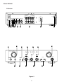
(Figure 2)