1
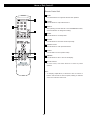
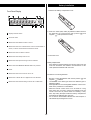
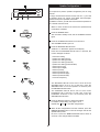
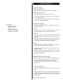
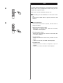
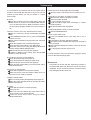
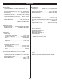
RV2600 DTS
AV Digital Home Theater Receiver
OWNER’S MANUAL
Contents
Thank you for choosing TEAC. Read this manual carefully to
get the best performance from this unit.
Contents . . . . . . . . . . . . . . . . . . . . . . . . . . . . . . . . . . . . . . . . . 2
Before Use . . . . . . . . . . . . . . . . . . . . . . . . . . . . . . . . . . . . . . . 3
How to Reset the Settings to the FACTORY DEFAULTS . . . . 3
Connection (FM antenna) . . . . . . . . . . . . . . . . . . . . . . . . . . . . 4
Connection (AM antenna) . . . . . . . . . . . . . . . . . . . . . . . . . . . . 5
Connection . . . . . . . . . . . . . . . . . . . . . . . . . . . . . . . . . . . . . . . 6
Speaker Connections . . . . . . . . . . . . . . . . . . . . . . . . . . . . . . 10
Positioning of the Speakers. . . . . . . . . . . . . . . . . . . . . . . . . . 11
Names of Each Control . . . . . . . . . . . . . . . . . . . . . . . . . . . . . 12
Battery Installation . . . . . . . . . . . . . . . . . . . . . . . . . . . . . . . . . 15
Speaker Configuration. . . . . . . . . . . . . . . . . . . . . . . . . . . . . . 16
Basic Operation . . . . . . . . . . . . . . . . . . . . . . . . . . . . . . . . . . . 20
Dubbing from VIDEO 2 or 3 to VIDEO 1 . . . . . . . . . . . . . . . . 24
Dubbing the audio and video signals separately . . . . . . . . . . 24
Surround Mode . . . . . . . . . . . . . . . . . . . . . . . . . . . . . . . . . . . 25
DOLBY PRO LOGIC IIx MUSIC parameters . . . . . . . . . . 29
Dynamic Range Compression. . . . . . . . . . . . . . . . . . . . . . . . 30
Tuner . . . . . . . . . . . . . . . . . . . . . . . . . . . . . . . . . . . . . . . . . . . 31
Preset Tuning . . . . . . . . . . . . . . . . . . . . . . . . . . . . . . . . . . . . 32
RDS . . . . . . . . . . . . . . . . . . . . . . . . . . . . . . . . . . . . . . . . . . . . 34
RDS Search. . . . . . . . . . . . . . . . . . . . . . . . . . . . . . . . . . . . . . 35
PTY Programs . . . . . . . . . . . . . . . . . . . . . . . . . . . . . . . . . . . 36
Troubleshooting. . . . . . . . . . . . . . . . . . . . . . . . . . . . . . . . . . . 37
Specifications . . . . . . . . . . . . . . . . . . . . . . . . . . . . . . . . . . . . 38
“DTS”, “DTS-ES” and “Neo:6” are trademarks of Digital
Theater Systems, Inc.
Manufactured under license from Dolby Laboratories.
“Dolby”, “Pro Logic” and the double-D symbol are
trademarks of Dolby Laboratories.
CAUTION Regarding Placement
To maintain proper ventilation, be sure to leave a space
around the unit (from the largest outer dimensions including
projections) equal to, or greater than, shown below.
CAUTION
The product shall not be exposed to dripping or splashing
and that no object filled with liquids, such as vases, shall be
placed on the product.
Left and Right Panels: 10 cm
Rear Panel
: 10 cm
Top Panel
: 50 cm
Do not install this equipment in a confined space such as a
book case or similar unit.
2
Before Use
Read this before operation
• As the unit may become warm during operation, always
leave sufficient space around the unit for ventilation.
The ventilation holes should not be covered. Make sure
there is at least 50 cm of space above and at least 10 cm of
space on each side of the unit. Do NOT place anything on
top of the unit.
• The voltage supplied to the unit should match the voltage
as printed on the rear panel. If you are in any doubt
regarding this matter, consult an electrician.
• Choose the installation location of your unit carefully. Avoid
placing it in direct sunlight or close to a source of heat. Also
avoid locations subject to vibrations and excessive dust,
heat, cold or moisture.
• Do not place the unit on the amplifier/receiver.
• Do not open the cabinet as this might result in damage to
the circuitry or electrical shock. If a foreign object should get
into the unit, contact your dealer or service company.
• When removing the power plug from the wall outlet, always
pull directly on the plug, never yank the cord.
• Do not attempt to clean the unit with chemical solvents as
this might damage the finish. Use a clean, dry or slightly
damp cloth.
• Keep this manual in a safe place for future reference.
How to Reset the Settings to the FACTORY DEFAULTS
Memory Backup
If the power supply is interrupted for 14 days or longer, the
settings kept in memory (such as preset stations and
speaker settings) will be erased.
Restoring factory settings
If you have made a lot of changes to the setup, and want to
restart from a known set of options, restore the unit to the
factory settings as follows:
1. With the unit in the standby mode, briefly press the
STANDBY/ON switch while holding down the
MEMORY/ENTER button.
• Release the MEMORY/ENTER button immediately after
pressing the STANDBY/ON switch.
The model name, etc. appears on the display.
2. Press the MEMORY/ENTER button.
The unit turns standby.
3. Press the POWER switch to turn the unit off.
All memories are erased, and the unit returns to the factory
settings.
3
Connection (FM antenna)
CAUTION:
• Switch off the power to all equipment before making
connections.
• Read the instructions of each component you intend to use
with this unit.
• Be sure to insert each plug securely. To prevent hum and
noise, avoid bundling the signal interconnection cables
together with the AC power cord or speaker cables.
A
A FM Indoor Antenna
In an area with strong FM signals, the T-type FM antenna
provided with this unit is sufficient.
Extend the antenna into a “T” shape and connect the two
wires at the base of the “T” to the provided matching
transformer, as shown.
After completing connection, plug the transformer into the
“FM 75Ω” socket. Extend the top of the “T” and tune the
tuner to your favorite station (see page 31). Adjust the
antenna in a suitable location like a window frame or wall
until the reception is best and then affix the antenna in that
position using thumb tacks, push pins or any other
suitable means.
B FM Outdoor Antenna
In an area where FM signals are weak, it will be necessary
to use an 75-ohm unbalanced-type outdoor FM antenna.
Generally, a 3-element antenna will be sufficient; if you
live in an area where the FM signals are particularly weak,
it may be necessary to use one with 5 or more elements.
B
•Disconnect the FM indoor antenna when using an outdoor
antenna.
4
Connection (AM antenna)
AM Indoor Loop Antenna
The high-performance AM loop antenna provided with this
unit is sufficient for good reception in most areas.
To stand the loop antenna on a surface, fix the claw to the
slot in the antenna base.
Connect the loop antenna’s wires to the AM antenna
terminals.
How to connect:
Press the lever, insert the end of the cord, then release
the lever. Make sure it is fastened securely by pulling the
cord lightly. Make sure only the bare, stripped wire is
inserted in the jack and that no plastic insulation is
preventing contact between the antenna wire and
terminal.
AM Outdoor Antenna
Antenne AM extérieure
Antena exterior AM
Place the antenna on a shelf or hang it on a window
frame, etc., in the direction which gives the best reception.
Keep all other wires such as power cords, speaker wires
or interconnect wires as far away as possible from the
antenna.
AM Loop Antenna
Antenne-cadre AM intérieure
Antena de cuadro de AM interior
• If the AM loop antenna provided does not deliver sufficient
reception (often due to being too far from the transmitter
or in a concrete building, etc.), it may be necessary to use
an outdoor AM antenna.
Use either a high quality commercial AM antenna or, if not
available, an insulated wire more than 5 m long, strip one
end, and connect this to the terminal as shown.
The antenna wire should be strung outdoors or indoors
near a window. For better reception, connect the GND
terminal to a reliable ground.
Note:
Even when using an outdoor AM antenna, do not
disconnect the AM loop antenna.
5
Connection 1
CD-R, MD, etc.
CAUTION:
• Switch off the power to all equipment before making
connections.
• Read the instructions of each component you intend to use
with this unit.
• Be sure to insert each plug securely. To prevent hum and
noise, avoid bundling the signal interconnection cables
together with the AC power cord or speaker cables.
DVD, CD, etc.
Connection to audio/video components
A
B
A DIGITAL IN terminals
Used for the input of digital audio signals. Connect these
digital input terminals to the appropriate digital output
terminals of the digital audio source unit such as a DVD or
CD player.
Use a good quality RCA coaxial cable or optical digital
cable.
C
C
B DIGITAL OUT terminal
The digital signals coming in through the DIGITAL IN
terminals are sent out through this terminal.
Connect to the digital input terminal of a digital recording
device such as a CD recorder using a commerciallyavailable optical digital cable.
When inserting the plug of the optical cable, the protective
shutter of the terminal will open and you should hear it
click into position when fully inserted. Be careful that you
do not force the plug, because this could result in damage
to the protective shutter, the cable, or the unit itself.
TAPE
C AUDIO IN/OUT jacks
D
Analog 2-channel audio signal is input or output from
these jacks. Connect the component with commerciallyavailable RCA cables.
Make sure to connect:
white plug
white jack (L: left channel)
red plug
red jack (R: right channel)
D EXTERNAL IN jacks
If your DVD player or decoder has 6 or 7-channel analog
audio outputs, connect them with good quality RCA
cables.
If the component to be connected has only 6 channel
outputs, do not use the SURROUND BACK jack.
DVD player or Decoder
6
F
E
H
G
DVD, VCR, etc.
TV (MONITOR)
Connection 2
Connection to a TV and video components
G AC OUTLET (switched)
Not available for AUSTRALIA, UK model.
This outlet is active only when the unit is on.
E COMPONENT IN/OUT jacks
COMPONENT VIDEO provides the best video quality and
should be used as your first choice.
Caution:
Make sure that the total power consumption of all
equipment connected to the outlet(s) does not exceed 100
watts.
If your DVD player and TV (or monitor) have
COMPONENT VIDEO jacks, connect them with quality
component video cables.
H AC Power Cord
F S-VIDEO or VIDEO jacks
After all other connections are complete, connect the plug
to the AC wall socket.
S-VIDEO connection is your second choice and is
superior to the standard composite video connection.
If the component has an S-VIDEO jack, connect it with a
high quality S-VIDEO cable.
If you are not going to use the unit for some time,
disconnect the power cord from the wall socket. (Leaving
the power cord unconnected for longer than 14 days will
cause the tuner memory presets to be lost.)
If neither COMPONENT VIDEO nor S-VIDEO is available,
connect the component with a high quality RCA cable
designed for video applications.
Be sure to connect the power cord to an AC outlet which
supplies the correct voltage.
Hold the power plug when plugging or unplugging the
power cord.
The video signal from COMPONENT, S-VIDEO or VIDEO
jacks cannot be mixed.
For example, the signal input into the COMPONENT IN
jacks is output from the COMPONENT OUT jacks only.
Be sure to connect all the components via the same kind
of jacks.
7
Example: Connection to a DVD player
8
Example: Connection to Video Cassette Recorders
9
Speaker Connections
Caution:
To avoid damaging the speakers with a sudden high-level
signal, be sure to switch the power off before connecting
the speakers.
Caution:
The metal portions of the two separate wires should not
touch or an electrical short can occur. Shorted wires can
create a fire hazard or induce a failure in your equipment.
How to connect:
Check the impedance of your speakers. Connect speaker
with an impedance of 6 ohms or more.
1. Turn the terminal cap counterclockwise to loosen it. The
speaker terminal caps cannot be fully removed from the
base.
The black speaker terminals are
(negative).
Generally, the
side of the speaker cable is marked to
make it distinguishable from the
side of the cable.
Connect this marked side to the
terminal and the
unmarked side to the black
terminal.
2. Insert the wire into the terminal fully and turn the terminal
cap clockwise to securely connect it:
Prepare the speaker cables for connection by stripping off
approximately 10 mm or less of the outer insulation.
(Removing too much insulation may lead to a short circuit if
the bared wired should come in contact with each other.)
Twist the strands of the stripped wires tightly together :
Make sure none of the wire insulation is under the terminal,
only the bare, stripped wire.
3. Make sure it is fastened firmly by pulling the cable lightly.
10
Positioning of the Speakers
The positioning of speakers differs according to the size
and acoustics of the listening room. While actually listening
to a program source, try various speaker positions to
determine which layout provides the best surround effect.
• Ideally, position all the speakers in a circle, with the same
distance from your listening position.
• Place the speakers connected to “L” to your left, and “R” to
your right.
A Front speakers
A
B
Use magnetically shielded speakers, if you are using them
near your TV.
Place the front speakers in front of the listening position, to
the left and right of a TV.
Front speakers are required for all surround modes.
A
E
B Center speaker
Use a magnetically shielded speaker if you are using it near
your TV. Place a center speaker between the front
speakers, on or below the TV. This speaker stabilizes the
sound image.
C
C
C Surround Left and Right speakers
Install these speakers above the level of the listener’s ears,
directly to the left and right (or slightly behind) of your
listening position.
D
D Surround Back speaker
Place the surround back speaker at the back of the listening
position facing the front at a slightly higher position than the
surround left and right speakers. Point slightly downward.
E Subwoofer
Reproduces powerful and deep bass sounds.
Use a sub-woofer with built-in amplifier referred to as a
“powered sub-woofer”. Subwoofers are most effective when
placed on or near the floor and in a corner of the room.
Refer to the instructions that came with your sub-woofer for
placement suggestions.
11
Names of Each Control 1
Front Panel
Remote Control Unit
12
A POWER
O PARAMETER
Press this switch to turn the unit standby or off.
Use this button to change parameters of DOLBY PRO
LOGIC IIx MUSIC.
The equipment draws nominal non-operating power from
the AC outlet with its POWER switch in the OFF position.
P PHONES
For private listening, insert the headphones plug into this
jack, and adjust the volume by turning the MASTER
VOLUME knob.
B STANDBY/ON
When the POWER switch of the main unit is depressed, use
this button to turn the unit on or standby.
Q CHANNEL SELECTOR
C SPEAKER
Select a speaker by pressing this button repeatedly, and
adjust the level using the LEVEL buttons.
Use this button to turn on or off the speakers.
on : Sound is output from the speakers.
off : No sound is output from the speakers.
R SELECT/LEVEL
Use these buttons to adjust the level of each speaker, etc.
D DIGITAL INPUTS
S TONE MODE
Use this button to select one of the digital input terminals.
Use this button to select a tone mode.
E Standby indicator
T SPEAKER SETUP
This indicator lights when the unit is in the standby mode.
When the unit is turned on, it goes off.
Use this button to start speaker configuration.
F Speaker indicator
U DYNAMIC RANGE
This indicator lights when the SPEAKER button is set to on.
Use this button to compress the dynamic range during
playback of a disc recorded in Dolby Digital.
G Remote Sensor
V MEMORY/ENTER
When operating the remote control unit, point it towards the
remote sensor.
Use this button to store preset channels into memory.
H Display
W TUNING/PRESET
When the unit is on, the current status of the unit is
displayed.
In the manual tuning mode, use these buttons to tune in a
station.
In the preset tuning mode, use these buttons to select a
preset channel.
I MASTER VOLUME
Turn this knob (or press the VOLUME buttons of the remote
control unit) to adjust the master volume.
X TUNING MODE
Use this button to select a tuning mode.
J INPUT SELECTOR
Y FM MODE
Use this buttons to select a source.
In FM tuner mode, use this button to select stereo or
monaural.
K EXTERNAL IN
Use this button to select the source connected to the
EXTERNAL IN jacks.
Z BAND
Use this button to select FM or AM.
L AUTO
a VIDEO 3 INPUT jacks
Use this button to change the decoding mode of digital
signals.
You can connect a component such as a portable CD,
game player, etc. to these jacks.
When using these jacks, remove the cap. When you don’t
use them, leave the cap in place.
M DSP
Use these buttons to select a surround mode.
N STEREO
b Buttons for RDS function (European models only)
Use this button to select stereo mode. Sound is output only
from the front speakers (and the sub-woofer).
In FM tuner mode, use these buttons for RDS function.
RDS is available in European countries only.
13
Names of Each Control 2
Remote Control Unit
A LEVEL
Use these buttons to adjust the level of each speaker.
B T.TONE
Use this button to output the test tone.
C SELECT
After pressing the SP SETUP or the PARAMETER button,
use these buttons to change the setting.
D SLEEP
Use this button to set sleep timer.
E MUTING
Use this button to mute the sound temporarily.
F PRESET SCAN
Use this button to scan preset channels.
G ENTER
Use this button to save speaker setup.
H DIMMER
Use this button to dim or turn off the display.
I Numeric buttons
In tuner mode, use these buttons to select a preset
channel.
Note:
• To simplify explanations, instructions refer to names of
buttons and controls on the front panel, making no mention
of the use of remote control unit.
14
Battery Installation
1. Remove the battery compartment cover.
Front Panel Display
VS
2. Insert two “AAA” (R03, UM-4) dry batteries. Make sure that
the batteries are inserted with their positive “ ” and
negative “ ” poles positioned correctly.
a displays current status.
b surround mode
c illuminates when RDS function is active.
d illuminates when the multi-channel sound is downmixed to
stereo, or when an FM stereo broadcast is tuned.
e illuminates when a station is tuned.
3. Close the cover.
f illuminates when sleep timer is set.
g illuminates when preset tuning mode is selected.
Battery Replacement
If the distance required between the remote control unit and
main unit decreases, the batteries are exhausted. In this
case replace the batteries with new ones.
h blinks when the MEMORY/ENTER button is pressed.
i meter
j illuminates when tone control is set to off.
Precautions concerning batteries
k illuminates or blinks when a digital source is selected.
• Be sure to insert the batteries with correct positive “ ” and
negative “ ” polarities.
• Use batteries of the same type. Never use different types of
batteries together.
• Rechargeable and non-rechargeable batteries can be used.
Refer to the precautions on their labels.
• When the remote control unit is not to be used for a long
time (more than a month), remove the batteries from the
remote control unit to prevent them from leaking. If they
leak, wipe away the liquid inside the battery compartment
and replace the batteries with new ones.
• Do not heat or disassemble batteries and never dispose of
old batteries by throwing them in a fire.
l illuminates when the decoding mode is set to “IN-AUTO”.
15
Speaker Configuration 1
It is important to perform speaker configuration prior to using
the unit.
To enjoy multi-channel surround sound, such as 5.1, you need
5 speakers (Front Left, Center, Front Right, Surround Right,
Surround Left) and a powered sub-woofer.
In addition to above, you will need a surround back speaker for
6.1 channel surround sound.
• When no action is taken for 8 seconds, the Speaker Setup
mode will be cancelled.
1
1 Press the POWER switch.
The unit enters standby mode, and the STANDBY indicator
lights.
2 Press the STANDBY/ON switch to turn the unit on.
The STANDBY indicator goes off.
2
3 Press the SPEAKER SETUP button.
“SUB-W Y” or “SUB-W N” appears on the display.
Each time the SPEAKER SETUP button is pressed, the
mode is changed as follows:
sub-woofer setting
speaker size setting (Front)
speaker size setting (Center)
speaker size setting (Surround)
speaker size setting (Surround Back)
distance (Front Left)
distance (Front Right)
distance (Center)
distance (Surround Left)
distance (Surround Right)
distance (Surround Back)
Crossover Frequency
3
4
• The SPEAKER SETUP button will not work when the
SPEAKER button is set to off. In that case, press the
SPEAKER button to turn the speakers on and then press
the SPEAKER SETUP button.
• The SPEAKER SETUP button will not work when
EXTERNAL IN is selected. In that case, press the
EXTERNAL IN button to turn it off and then press the
SPEAKER SETUP button.
5
4 Press the SELECT buttons to change the setting.
For details of each setting, see page 17 to 19.
Repeat step 3 and 4 to set other configurations.
5 When all the configurations has been finished, press the
MEMORY/ENTER button to save the changes and exit the
Speaker Setup mode.
Be sure to press the MEMORY/ENTER button within 8
seconds, or the changes will be cancelled.
16
Speaker Configuration 2
Subwoofer Setting
SUB W-Y (Subwoofer-Yes):
Select this when a powered sub-woofer is connected.
SUB W-N (Subwoofer-No):
Select this when no sub-woofer is connected.
• If you select “SUB-W N (no subwoofer)”, the front speaker
is automatically set to “L”.
• To enjoy the full home theater experience, we recommend
the use of a powered sub-woofer.
Speaker Size Setting
Abbreviations
FRONT L: front left
FRONT R: front right
CENTER: center
SURR L: surround left
SURR R: surround right
SURR-B: surround back
Each time the SELECT button is pressed, the setting is
changed as follows:
L (Large):
Select this when the connected speakers can fully
reproduce sounds below the Crossover Frequency.
S (Small):
Select this when the connected speakers are rather small
and cannot reproduce sounds below the crossover
frequency.
When this setting is selected, bass frequencies below the
crossover frequency are output from the sub-woofer (if no
sub-woofer is connected, from the front speakers).
N (None):
Select this when no speaker is connected. The sound is
output from the front (or surround) speakers.
• Depending on your selection, settings available for each
speaker changes.
• When the surround left and right speakers are set to “SURR
N (none)”, the surround back speaker is also set to “SURRB N (none)” automatically.
Distance (front, center, surround)
Input the distance from your listening position to front,
center and surround speakers. The delay time is
automatically adjusted to improve the surround effect.
You can change the setting from 0.1 to 9 meters, at 0.1
meter’s step.
Crossover Frequency
You can change the setting from 40 to 130 Hz in 10 Hz
steps.
When the speaker size is set to “Small”, bass frequencies
below the crossover frequency you set here are output from
the sub-woofer (if no sub-woofer is connected, from the
front speakers).
The default setting is 80 Hz.
17
Speaker Configuration 3
Balancing relative volume between speakers using
Test Tone
1
The test tone function is useful to adjust the relative volume
between speakers.
Once the balance is set, you don’t have to change the
balance as long as the speakers aren’t moved.
• It is also possible to adjust the relative volume during
playback of DVD. See 19 page for details.
• Use the remote control from your listening position.
• The T.TONE button will not work when the SPEAKER
button is set to off. In that case, press the SPEAKER button
to turn the speakers on.
• The T.TONE button will not work when EXTERNAL IN is
selected. In that case, press the EXTERNAL IN button to
turn it off.
2
1 Press the T.TONE button.
The test tone is emitted from each speaker in the following
order at 2.5-second intervals.
FL, C, FR, SR, SB, SL, SW
• If certain speakers are not being used, (for example, no
center speaker) the noise sequencer will automatically skip
over that channel.
3
2 Adjust the master volume to the normal listening level.
3 Adjust the volume of each speaker so that the test tone
from each speakers sounds the same.
• The level of the speaker emitting the test tone can be
changed by pressing the LEVEL buttons.
• The level can be adjusted in 1 dB steps from –15 dB to +15
dB.
• If you press the CH.SEL (CHANNEL SELECTOR) button,
the test tone stays there. To go to the next speaker, press
the CH. SEL button again.
4
4 When the setting has been finished, press the T.TONE
button to stop the test tone.
18
Speaker Configuration 4
Balancing relative volume between speakers during
playback of DVD
1 (During playback of DVD,) press the CH.SEL (CHANNEL
SELECTOR) button.
Each time the CH.SEL button is pressed, the channel is
changed as follows:
1
REF.1 or REF.2: stored setting
USER: “USER” appears only when the current setting is
different from REF.1 or REF.2.
If the balance has already been set using the test
tone function, you don’t have to change the setting of
speakers.
If you want to change the LFE level for Dolby Digital or
DTS, press the CH.SEL button repeatedly until “DD L
(Dolby Digital LFE)” or “DTS L (DTS LFE)” appears on the
display.
(LFE: Low Frequency Effect)
• A speaker set to “None” or “No” will not appear on the
display.
• When STEREO or Virtual Surround is selected, or when the
SPEAKER button is set to off, only the front speakers will
appear on the display.
2
2 Within 5 seconds, press the LEVEL buttons to change the
level.
• The level of speakers can be adjusted in 1 dB steps from
–15 dB to +15 dB.
• The LFE level can be adjusted in 1 dB steps from –10 dB to
0 dB. The default setting is 0 dB. Lower the LFE level if
necessary.
Repeat step 1 and 2 to change other settings.
When all the configurations have been finished, leave the
unit idle for 5 seconds to exit the Channel Select mode.
How to store your channel level setting
1. When all the settings have been finished in step 2, press
the MEMORY/ENTER button of the main unit.
“1” blinks on the display.
2. Within 5 seconds, press the LEVEL button to select “REF.1”
or “REF.2”.
3. Within 3 seconds, press the MEMORY/ENTER button to
save and exit.
How to call the stored setting
1. Press the CH.SEL button to display USER, REF.1 or REF2.
19
2. Press the LEVEL button to select “REF.1” or “REF.2”.
Basic Operation 1
1 Press the POWER switch.
The unit enters standby mode, and the standby indicator
lights.
2 Press the STANDBY/ON switch to turn the unit on.
The power indicator lights, and the standby indicator goes
off.
1
3 Select a source by pressing one of the INPUT SELECTOR
buttons(or pressing one of the INPUT SEL buttons of the
remote control unit).
The selected source is shown on the front panel’s display.
2
• If one of the INPUT SELECTOR buttons or EXT IN button
of the remote control unit is pressed in the standby mode,
the unit is turned on with the selected source automatically.
• If the source is connected to EXTERNAL IN jacks, press
the EXTERNAL IN button and proceed to step 5 .
4 When you selected VIDEO(1, 2 or 3) or CD in step 3 ,
3
press the DIGITAL INPUTS button repeatedly to select the
terminal.
o1: Select this when the source is connected to DIGITAL
IN (OPTICAL 1) terminal.
c1: Select this when the source is connected to DIGITAL
IN (COAXIAL 1) terminal.
c2: Select this when the source is connected to DIGITAL
IN (COAXIAL 2) terminal.
A: Select this when the source is connected to analog
AUDIO IN jacks.
• Each time the “AUDIO” button is pressed, the
input source changes as follows;
TUNER
CD
TAPE
AUX
• DIGITAL indicator blinks when the unit cannot perceive the
digital signal. In that case, connect a digital device to the
DIGITAL IN terminal, switch it on, and select the terminal by
pressing the DIGITAL INPUTS button.
(frequency display)
• Each time the “VIDEO” button is pressed, the
input source changes as follows;
VIDEO 1
VIDEO 2
VIDEO 3
• You can hear the sound from the selected DIGITAL IN
terminal as far as VIDEO (1,2 or 3) or CD has been
selected in step 3 .
4
5 Play the source, and gradually turn up the volume to the
required level by turning the VOLUME knob.
Recording a Source
1. Select a source to be recorded by pressing the INPUT
SELECTOR buttons (or pressing one of the INPUT SEL
buttons of the remote control unit).
5
2. Start recording.
• The volume and tone control have no effect on the
recording signals.
• The analog signals input from the EXTERNAL IN jacks
cannot be recorded.
20
Basic Operation 2
A
A Speaker On/Off
Press the SPEAKER button to turn the speakers on or off.
When ON is selected, the SPEAKER indicator lights.
B Headphones
B
For private listening, first reduce the volume level on the
receiver to minimum. Then insert the plug from your
headphones into the PHONES jack, and adjust the
volume by turning the VOLUME knob.
If you want to cut off the sound from speakers, press the
SPEAKER button to turn it off.
•When the SPEAKER button is set to off, the multichannel sound is downmixed to 2 channel automatically.
•When EXTERNAL IN is selected, only the front left and
right channels are output from the PHONES jack.
21
Basic Operation 3
C EXTERNAL IN (7 channel direct input)
C
If the source is connected to EXTERNAL IN jacks, press
the EXTERNAL IN button. “EXT IN” appears on the
display, and up to 7 discrete analog signals can be heard
from speakers.
Press the EXTERNAL IN button again (or select any other
source by turning the INPUT SELECTOR button) to
cancel the EXTERNAL IN function.
D Muting
D
To mute the sound temporarily, press the MUTING button.
Press the MUTING button again to restore the sound. If
you change the volume during the muting, the muting will
be cancelled.
MUTING
• While muting is engaged, “MUTE” blinks on the display.
E Dimmer
E
You can dim or turn off the front panel’s display by
pressing the DIMMER button:
• When the display is turned off, pressing any button will
turn the display on.
• This function will be cancelled when the STANDBY/ON or
the POWER switch is pressed.
• When you set the sleep timer, the display is dimmed
automatically.
22
Basic Operation 4
F
F Tone Control
1. Press the TONE MODE button.
“TONE OFF” or “TONE ON” appears on the display.
• If no button is pressed for 5 seconds, the tone mode will
be cancelled.
• The TONE MODE button will not work when EXTERNAL
IN is selected.
2. If the tone mode is off, press the LEVEL button to turn it
on.
3. Press the TONE MODE button to select “BASS” or
“TRBL”.
Each time the TONE MODE button is pressed, the mode
is changed as follows:
To adjust the level of low frequency sound range, select
“BASS”.
To adjust the level of high frequency sound range, select
“TRBL (treble)”.
4. Press the LEVEL buttons to change the setting.
The level can be adjusted in 1 dB steps from –10 to +10.
• If you want to turn off the tone mode, select “TONE ON”
and press the LEVEL button to turn it off. “DIRECT”
indicator lights.
• Tone control does not work when the digital signals of
DTS or Dolby Digital are input, or when EXTERNAL IN is
selected.
G Sleep Timer
G
The power can be switched off after a specified amount of
time.
Press the SLEEP button repeatedly until desired time
appears on the display.
SLEEP 10 (20 ... 90):
The power will be switched off 10 (20 ... or 90) minutes
later.
Normal display: the sleep timer is off.
When you set the sleep timer, the display is dimmed, and
the remaining time is displayed.
23
Dubbing from VIDEO 2 or 3 to VIDEO 1
1 Select VIDEO 2 or 3 by pressing the VIDEO button.
2 Start recording on the VCR connected to VIDEO 1 REC
jacks.
3 Start playback on the VCR connected to VIDEO 2 or 3
INPUT jacks.
The audio and video signals input from VIDEO 2 or 3 are
output from VIDEO 1 REC jacks.
• Copy protected DVD discs cannot be dubbed.
• The video signal from S-VIDEO or VIDEO jacks cannot be
mixed. Be sure to connect all the components via the same
kind of jacks.
Dubbing the audio and video signals separately
1
While dubbing the video signal of VIDEO 2 or 3, you can
replace the sound from VCR with the sound from an audio
source such as CD.
1 Select the video source to be recorded (VIDEO 2 or 3)
using the INPUT SELECTOR buttons of the remote control
unit.
2 Select the audio source to be recorded (CD, TAPE, etc.)
using the INPUT SELECTOR buttons of the remote control
unit. Do not turn the INPUT SELECTOR buttons of the main
unit, or the video source selection in step 1 might be
cancelled.
2
3 Start recording on the VCR connected to VIDEO 1 REC
jacks.
4 Start playback of the video and audio source to be
recorded.
The picture from the video component appears on the TV,
and the sound from the audio component is output from the
speakers.
24
Surround Mode 1
• When EXTERNAL IN is selected, the DSP and the AUTO
button do not work.
1 If a digital device is connected to DIGITAL IN terminals,
1
select desired decoding mode by pressing the AUTO
button.
Each time the AUTO button is pressed, the decoding mode
is changed as follows:
IN-AUTO (default):
The appropriate decoding mode is selected automatically.
Usually, select this.
IN-DTS:
Select this only when the input signal is DTS.
IN-PCM:
Select this only when the input signal is PCM.
• The AUTO button works only when the function is set to
VIDEO or CD and the digital input is selected.
• When IN-AUTO is selected, noise may be heard during
playback of a DVD recorded in DTS format. In this case,
select IN-DTS.
• If the selected decoding mode does not match with the
input signal, “DIGITAL” indicator will blink and no sound will
be heard.
2 Select the desired surround mode by pressing the DSP
2
button.
Each time the DSP button is pressed, the surround mode
changes.
A When Dolby Digital signals are input and IN-AUTO is
selected, the surround mode is set to DOLBY DIGITAL
automatically.
If you press the DSP button, you can select one of the
following surround modes:
When the source is Dolby Digital EX:
DOLBY DIGITAL EX, VIRTUAL NARROW, VIRTUAL
WIDE
When the source is Dolby Digital 5.1:
DOLBY DIGITAL, VIRTUAL NARROW, VIRTUAL WIDE,
DOLBY PRO LOGIC IIx MOVIE, DOLBY PRO LOGIC IIx
MUSIC
When the source is Dolby Digital 2-channel:
DOLBY PRO LOGIC IIx MOVIE, DOLBY PRO LOGIC IIx
MUSIC, DOLBY PRO LOGIC, VIRTUAL NARROW,
VIRTUAL WIDE
B When DTS signals are input and IN-AUTO or IN-DTS is
selected, the surround mode is set to DTS or DTS-ES
automatically.
If you press the DSP button, you can select one of the
following surround modes:
25
When the source is DTS-ES:
DTS-ES
When the source is DTS:
DTS, DTS+NEO:6
Surround Mode 2
C When MPEG signals are input and IN-AUTO is selected,
the surround mode is set to MPEG automatically. The DSP
button doesn’t work.
D When the source is PCM (2-channel stereo) and IN-AUTO
or IN-PCM is selected, or when analog stereo signals are
input, you can select one of the following surround modes:
DOLBY PRO LOGIC IIx MOVIE, DOLBY PRO LOGIC IIx
MUSIC, DOLBY PRO LOGIC, VIRTUAL NARROW,
VIRTUAL WIDE, DTS NEO:6 CINEMA, DTS NEO:6
MUSIC, THEATER, HALL, STADIUM
• When the DSP button is pressed once, the current surround
mode is displayed. Press the DSP button repeatedly to
select any other surround mode.
• When you press the DSP button, the sound is cut off for a
moment.
• When the surround back speaker is set to “None”, Dolby
Pro Logic II appears instead of Dolby Pro Logic IIx.
• DOLBY DIGITAL or DOLBY DIGITAL EX can be selected
only during playback of a DVD disc recorded in DOLBY
DIGITAL format.
• The DSP indicator lights when THEATER, HALL or
STADIUM is selected.
(DSP: Digital Signal Processor)
STEREO
Press the STEREO button to select the stereo mode.
“STEREO” is scrolled, and sound is output from front
speakers (and the sub-woofer if connected).
To cancel the stereo mode, select any other surround mode
by pressing the DSP button.
• If you select the stereo mode while the digital signal of
DOLBY DIGITAL or DTS are being input, the multi-channel
sound is downmixed to 2-channel.
• If the SPEAKER button is set to off while the digital signal of
DOLBY DIGITAL or DTS are being input, the multi-channel
sound is downmixed to 2-channel automatically. And when
the SPEAKER button is set to on, it will return to the
previous surround mode.
26
Surround Mode 3
Surround Mode 4
DTS (DTS Digital Surround)
DTS NEO:6
During playback of a DVD disc recorded in DTS format, the
surround mode is set to DTS automatically.
With the high precision digital matrix decoder used for DTSES Matrix 6.1, DTS NEO:6 gives you 6.1 multi-channel
surround sound from any stereo source.
• DTS NEO:6 will not work on monaural source.
DTS Digital Surround delivers up to 5.1 channels with lower
audio compression than Dolby Digital. It provides the clarity
and dynamics of the original master soundtrack.
DTS NEO:6 Cinema
This mode is optimized for movies.
Decoding is performed with emphasis on separation
performance to achieve the same atmosphere with 2channel sources as with 6.1-channel sources.
DTS-ES (Extended Surround)
This is a new multi channel digital signal format that greatly
improves the 360-degree surround impression and space
expression thanks to further expanded surround signals.
This format is compatible with the conventional DTS format.
In addition to the 5.1 channels of DTS, DTS-ES also offers
the surround back (sometimes also referred to as “surround
center”) channel for surround playback with a total of 6.1
channels. For the optimum playback of DTS-ES, you need
6 speakers and a powered sub-woofer.
DTS NEO:6 Music
This mode is suitable for music.
The front left and front right signals bypass the decoder and
are played directly so there is no loss of sound quality, and
the effect of the surround signals from the center, surround
left, surround right and surround back channels adds a
natural sense of expansion to the sound field.
• The surround back channel information is matrixed into the
surround left and right channels. When played with 5
speakers, the surround back channel signals are output
from the surround left and right speakers so that none of
the signal components are lost.
Dolby Digital
During playback of a DVD disc recorded in DOLBY
DIGITAL format, the surround mode is set to DOLBY
DIGITAL or DOLBY DIGITAL EX automatically.
There are two formats for DTS-ES:
Dolby Digital delivers up to 5 totally discrete, full frequency
audio channels (front left and right, center, and surround left
and right), plus 0.1 channel called LFE (Low-Frequency
Effects). LFE delivers a separate non-directional bass
signal to the sub-woofer for more dynamic deep bass sound
effects.
DTS-ES Discrete 6.1
Because the signals for 6.1 channels (including the
surround back channel) are fully independent, it is possible
to achieve a sense that the acoustic image are moving
about freely among the background sounds surrounding the
listener from 360 degrees.
Dolby Digital Surround EX
DTS-ES Matrix 6.1
With this format, the additional surround back channel
signals undergo matrix encoding and are input to the
surround left and surround right channels beforehand.
During playback, they are decoded to the surround left,
surround right and surround back channels.
This mode creates the back (sometimes also referred to as
“surround center”) signals from the surround left and right
signals in Dolby Digital 5.1 channel source using a matrix
decoder and provides 6.1 channel surround playback. With
this additional channel, you can experience more dynamic
and realistic moving sound.
When DTS-ES Discrete 6.1 or Matrix 6.1 sources are
decoded with a DTS-ES decoder, the format is
automatically detected upon decoding and the optimum
surround mode is selected.
• As the surround back channel is matrix-encoded onto the
left and right surround channels, no information is lost when
played with 5 speakers.
• When Dolby Digital EX sources are decoded with a Dolby
Digital EX decoder, the format is automatically detected
upon decoding and the Dolby Digital EX mode is selected.
However, some Dolby Digital EX sources may be detected
as Dolby Digital sources. In this case, the Dolby Digital EX
mode should be selected manually to play these sources.
27
Surround Mode 5
Surround Mode 6
THEATER
Dolby Pro Logic IIx and Dolby Pro Logic II
Dolby Pro Logic IIx technology processes any native stereo
or 5.1 signal into a 6.1- or 7.1-channel output, creating a
seamless, natural surround soundfield that immerses you in
the entertainment experience.
This mode provides a three dimensional surround effect
similar to that of movie theater.
HALL
This mode is suitable for orchestral music such as classical
music or opera.
Dolby Pro Logic II technology gives you 5.1-channel
surround sound from any stereo program material, as well
as Dolby Surround encoded material.
STADIUM
This mode provides the expansive sound field to achieve
the true stadium effect when watching baseball or
soccer games.
• When the surround back speaker is set to “None”, Dolby
Pro Logic II appears instead of Dolby Pro Logic IIx.
MOVIE mode:
This mode is optimized for movies or Dolby Surround
encoded materials. This mode is also appropriate for use
with video games.
MUSIC mode:
The Music mode creates a rich and enveloping surround
ambience from stereo sources such as music CDs.
Music mode also features three additional user controls:
Dolby Center Width adjusts the balance of the main
vocals in the center and front channels.
Dolby Panorama creates a seamless, wraparound
surround effect.
Dolby Dimension creates a deeper or shallower surround
sound field.
• DOLBY PRO LOGIC IIx and DOLBY PRO LOGIC II will not
work on monaural source.
Dolby Pro Logic
Dolby Pro Logic is a matrix decoder that decodes the four
channels of surround sound (front left, center, front right
and surround) that have been encoded onto the stereo
soundtracks of Dolby Surround encoded material such as
VHS movies. The surround channel is monaural, but is
played through two surround speakers.
Dolby Virtual
This mode employs sophisticated digital processing to
create the illusion of "phantom" speaker, this mode allows
you to experience surround sound effects from Dolby
Digital, Dolby Surround or 2-channel (recorded in digital
PCM or analog stereo) source, through just a single pair of
front speakers.
28
DOLBY PRO LOGIC IIx MUSIC parameters
You can adjust the parameters for DOLBY PRO LOGIC IIx
MUSIC.
1 Select DOLBY PRO LOGIC IIx MUSIC mode by pressing
1
the DSP button.
2 Select the parameter to be changed by pressing the
2
PARAMETER button.
Each time the PARAMETER button is pressed, the
parameter is changed as follows:
3 Within 8 seconds, press the SELECT button to change the
3
value.
PANO (panorama):
This mode extends the front stereo image to include the
surround speakers for an exciting wraparound effect with
side wall imaging. Select “ON” or “OFF”.
The default setting is “OFF”.
C-WID (center width control):
This adjusts the center image so it may be heard only
from the center speaker, only from the left/right speakers
as a phantom image, or from all three front speakers to
varying degrees.
The adjustable range is from 0 to 7. The default setting is
“0”.
DIMEN (dimension control):
This adjusts the sound-field either towards the front or
towards the rear. The adjustable range is from –4 to +2.
The default setting is “–1”.
Repeat step 2 and 3 to adjust other parameters.
When all the configurations have been finished, leave the
unit for 8 seconds to exit.
29
Dynamic Range Compression
In many listening situations, you may find loud passages
objectionable. Adjusting this setting allows you to compress
the sounds into a range that you may find more suitable for a
particular listening situation. Dolby Digital satisfies these
needs through the dynamic range controlling.
Select one of the followings to fit the individual listening
situation of the audience.
During playback of DVD, press the DYNAMIC RANGE button
repeatedly until desired setting appears on the display.
DYNR 0.0 (off):
Audio with uncompressed dynamic range. Select this
when you don’t want to compress the dynamic range.
DYNR 0.5:
Audio with partially compressed dynamic range.
DYNR 1.0:
Audio with fully compressed dynamic range.
• The default setting is “DYNR 0.0”.
• This function is effective only when playing back a DVD
disc recorded in Dolby Digital format on the DVD player
connected via DIGITAL IN terminal. This control has no
effect on other discs.
• This function may not work with some discs.
30
Tuner 1
1 Select TUNER by press the AUDIO button (or press the
TUNER button of the remote control unit).
Make sure the antennas have been connected (see page
4).
2 Select AM or FM by pressing the BAND button (or press the
TUNER button of the remote control unit).
• If the BAND button is pressed while the source other than
TUNER was selected, the source will be switched to
TUNER automatically.
1
3 Press the TUNING MODE button to select the tuning mode.
Each time the TUNING MODE button is pressed, the tuning
mode changes as follows:
Automatic tuning mode
(“AUTO” indicator lights on the display.)
Manual tuning mode
2
(no indicator)
Preset tuning mode
(“PRESET” indicator lights.)
Select the Manual tuning mode or the Automatic tuning
mode.
3
• When using the remote control unit, you can skip this step.
4 Press the TUNING/PRESET button to tune in a station.
In the Automatic tuning mode, the unit starts searching for a
station. When a station is tuned in, the tuning process will
stop automatically.
If you want to stop the tuning process, press the TUNING
MODE button.
4
In the Manual tuning mode, hold down the
TUNING/PRESET button and release it when the station is
tuned in.
When the TUNING/PRESET button is pressed
momentarily, the frequency changes by a fixed step (FM:
50 kHz steps, AM: 9 kHz steps).
31
Tuner 2
FM MODE Button
Pressing this button alternates between Stereo mode and
Mono mode.
Stereo:
FM stereo broadcasts are received in stereo and the “ST”
indicator lights in the display.
Mono:
To compensate for weak FM stereo reception, select this
mode. Reception will now be forced monaural, reducing
unwanted noise.
Preset Tuning 1
You can store up to 30 stations.
Manual Memory Presetting
1 Tune in a station you want to listen to (see steps 1 to 4 of
page 31).
2 Press the MEMORY/ENTER button.
2
3 While the “MEM” indicator is blinking, select a preset
channel to store the station using the TUNING/PRESET
buttons (or the PRESET buttons of the remote control unit),
and then press the MEMORY/ENTER button.
3
You can also use the numeric buttons to select a preset
channel.
Example:
To select channel No. 3:
To select channel No. 16:
To select channel No. 30:
For instance, to select preset number 25, press “2” and “5”.
To select numbers less than 10, press “0” and then the
number. As an example, to select number 5, press “0” and
“5”. (Optionally, you may press just the number “5” and then
wait a few seconds.)
When using the numeric buttons, the station is stored
automatically without pressing the MEMORY/ENTER
button.
To store more stations, repeat steps 1 to 3 .
32
Preset Tuning 2
How to select preset stations
1
1 If “PRESET” indicator isn’t lit, press the TUNING MODE
button to select the preset tuning mode.
• When using the remote control unit, you can skip this step.
2 Select a preset channel using the TUNING/PRESET
2
buttons (or the numeric buttons of the remote control unit).
Scanning preset stations
Press the PRESET SCAN button of the remote control unit.
Preset stations stored in memory are scanned at 5 seconds
intervals.
When the station you want to listen to is found, press the
PRESET SCAN button again to stop scanning.
33
RDS
The Radio Data System(RDS) is a broadcasting service which
allows stations to send additional information along with the
regular radio programme signal.
1
RDS works on the FM waveband in Europe only.
1 Select FM by press the TUNER button of the remote control
unit.
Each time the TUNER button is pressed, the FM or AM
changed.
2 Press the RDS button.
2
Each time the RDS button is pressed, the RDS mode is
changed as follows:
PS (Programme Service name)
displays PS or a station’s name. If there is no PS data,
“NO NAME” will be displayed.
PTY (Programme Type)
displays the programme type. If there is no PTY data, “NO
PTY” will be displayed.
CT (Clock Time)
displays the information about times provided from the
station.
If there is no time data, “NO TIME” will be displayed.
RT (Radio Text)
displays the news of stations composed of up to 64
symbols.
If there is no RT data, “NO TEXT” will be displayed.
34
RDS Search
A station can be searched by this function.
1
1 Select FM by press the TUNER button of the remote control
unit.
2 Press the SEARCH MODE button.
Each time the SEARCH MODE button is pressed, the
search mode is changed as follows:
RDS search
2
Select “RDS SRCH” by pressing the SEARCH MODE
button, and within 8 seconds press the SELECT button.
The unit starts searching and “RDS SRCH” blinks.
When a station offering RDS services is found, the station’s
name will be displayed.
If the station found is not the desired one, press the
SELECT button again while the RDS indicator is blinking.
If no RDS station is found, “NO RDS” will be displayed.
TP search
Select “TP SRCH” by pressing the SEACH MODE button,
and within 8 seconds press the SELECT button.
The unit starts searching for a station offering the traffic
programme, and “TP SRCH” blinks.
If no station is found or the signal is too weak, “NO TRAFF”
will be displayed.
PTY search
1. Select “PTY SRCH” by pressing the SEACH MODE button.
2. Within 8 seconds, select the desired PTY programme by
pressing the PTY SELECT button.
You can select from 31 kinds (see page 36).
3. Press the SELECT button.
The unit starts searching.
When the programme that you have selected is found,
searching will stop and the programme type will be
displayed.
If no station is found or if the signal is too weak, “NO
PROG” will be displayed.
35
PTY Programs
NEWS
: brief announcements, events, public opinion,
reports, actual situations.
AFFAIRS : a kind of suggestion including practical
announcements other than news, documents,
discussion, analysis and so on.
INFO
: daily information or reference such as weather
forecast, consumer guide, medical assistance
and so on.
SPORT
: sports related programs.
EDUCATE : educational and cultural information.
DRAMA : all kinds of radio concert and serial drama.
CULTURE : all aspects of national or local culture including
religious events, philosophy, social science,
language, theatre, and so on.
SCIENCE : programs on natural science and technology
VARIED : popular programs such as quiz, entertainment,
private interview, comedy, satire and so on.
POP M
: program on commercial, practical and popular
songs, and sale volume of discs, etc.
ROCK M : practical modern music generally composed and
played by young musicians.
EASY M : popular music usually lasting for less than 5
minutes.
LIGHT M : classical music, instrumental music, chorus, and
light music favored by non-professionals.
CLASSICS: orchestra including great operas, symphony,
chamber music and so on.
OTHER M : other music styles(Rhythm & Blues, Reggae, etc.)
WEATHER: weather reports, forecast
FINANCE : financial reports, commerce, trading
CHILDREN :
children’s programs
SOCIAL : social affairs
RELIGION : religious programs
PHONE IN : program in which the public expresses its view by
phone.
TRAVEL : travel reports
LEISURE : programs concerning recreational activities
JAZZ
: jazz music
COUNTRY: country music
NATION M : national music
OLDIES : music from the so-called golden of popular music
FOLK M : folk music
DOCUMENT : documentaries
TEST
ALARM
: a program notifying an emergency or a natural
disaster.
NONE
: No programme type or undefined.
36
Troubleshooting
Cannot view the on-screen display as it rolls rapidly.
The color system of the receiver does not match your TV.
If you experience any problems with the unit, please take a
moment to look through this chart and see if you can solve the
problem yourself before you call your dealer or a TEAC
service center.
Cannot listen to any station, or signal is too weak.
Make sure the antenna is properly connected.
Tune in the station properly.
If a TV is near the unit, turn it off.
Install the antenna again after relocating it to a better
reception position.
An external antenna may be required.
No power
Check the connection to the AC power supply. Check and
make sure the AC source is not a switched outlet and that,
if it is, the switch is turned on. Make sure there is power to
the AC outlet by plugging another item such as a lamp or
fan.
Though the broadcast is stereo, it sounds monaural.
Press the FM MODE button.
There is no sound or only a very low-level sound is heard.
Adjust the volume by turning the MASTER VOLUME
knob.
If the SPEAKER indicator isn’t lit, press the SPEAKER
button to turn it on.
Check that the speakers and components are connected
securely.
Check the operation of the connected component.
Check the audio output setting of your DVD player.
Select the proper source using the INPUT SELECTOR
buttons and the DIGITAL INPUTS button.
Select the proper surround mode (see page 25).
If “MUTE” is blinking on the display, press the MUTING
button to restore the sound.
Remote control doesn’t work.
Press the POWER switch of the main unit to turn it
standby.
If the batteries are dead, change the batteries.
Use remote control unit within the range (5m) and point at
the front panel.
Clear obstacles between the remote control unit and the
main unit.
If a strong light is near the unit, turn it off.
If normal operation cannot be recovered, unplug the power
cord from the outlet and plug it again.
No sound from surround or center speakers.
Check the speaker setting (see page 16).
Check the channel level setting (see page 18-19).
Select the proper surround mode (see page 25).
Check the audio output setting of your DVD player. Play a
multi-channel source.
Maintenance
If the surface of the unit gets dirty, wipe with a soft cloth or
use diluted mild liquid soap. Be sure to remove any excess
completely. Do not use thinner, benzine or alcohol as they
may damage the surface of the unit.
Severe hum or noise is heard.
Check that the speakers are connected securely.
Make sure the line cords and speaker cables are as far
away from the AC supply as possible.
“DIGITAL” indicator blinks.
The unit cannot perceive the digital signal (see page 20).
Select the proper decoding mode by pressing the AUTO
button (see page 25).
No picture.
Check that the system is connected properly.
Turn on the TV.
Make sure you have selected the proper video input on
the TV so that you can view the pictures.
Select the proper video source using the INPUT
SELECTOR buttons.
37
Specifications
AM Tuner Section
Tuning Range. . . . . . . . 522 kHz to 1,611 kHz (9 kHz steps)
Usable Sensitivity . . . . . . . . . . . . . . . . . . . . . . . . . 500 µV/m
Total Harmonic Distortion . . . . . . . . . . . . . 1.5% at 100 dB/m
Signal-to-Noise Ratio . . . . . . . . . . . . . . . 40 dB at 100 dB/m
Amplifier Section
Output Power (Stereo, 0.2 % THD, 20 Hz to 20 kHz, 6 Ω)
100 W + 100 W
Surround Output Power (0.7 % THD, 1 kHz, 6 Ω, only one
channel driven) . . . . . . . . . . . . . . . . . . . . 125 W per channel
Total Harmonic Distortion . . . . 0.09 % (at 95 W, 1 kHz, 6 Ω)
Audio Input Sensitivity/Impedance . . . *LINE: 200 mV/47 kΩ
Output Level/Impedance (TAPE REC) . . . . 200 mV / 2.2 kΩ
Frequency Response . . *LINE: 20 Hz to 50 kHz, +0 / –3 dB
Signal-to-Noise Ratio . . . . . . . . . . . . . *LINE: 90 dB (IHF-A)
Tone Control . . . . . . . . . . . . . . . . . BASS: ± 10 dB at 100 Hz
TREBLE: ± 10 dB at 10 kHz
General
Power Requirements . . . . . . . . . . . . . . . . . AC 230 V, 50 Hz
Power Consumption . . . . . . . . . . . 250 W (STANDBY : 3 W)
AC Outlet (except AUSTRALIA / UK model, total 100 W
max.) . . . . . . . . . . . . . . . . . . . . . . . . . . . . . . . . . switched x 1
Dimensions (W x H x D) . . . . . . . . . . . . 440 x 143 x 372 mm
Weight (net). . . . . . . . . . . . . . . . . . . . . . . . . . . . . . . . 10.4 kg
Digital Audio Section
Sampling Frequency . . . . 32 kHz, 44.1 kHz, 48 kHz, 96 kHz
Digital Input Level . . . . . . . . . . . . COAXIAL(75 Ω): 0.5 Vp-p
OPTICAL(660nm): –15 dBm to –21 dBm
Standard Accessories :
AM Loop Antenna x 1
FM T-type Antenna x 1
FM Matching Transformer x 1
Remote Control Unit x 1
Battery (AAA, R03, UM-4) x 2
Owner’s Manual x 1
Video Section
S-Video output
Y (luminance) - Output level . . . . . . . . . . . . 1 Vp-p (75 Ω)
C (color) - Output level. . . . . . . . . . . . . 286 mVp-p (75 Ω)
Jacks . . . . . . . . . . . . . . . . . . . . . . . . . . . . . S-VIDEO jack
* LINE means CD, TAPE, VIDEO.
Video output
Output level. . . . . . . . . . . . . . . . . . . . . . . . . 1 Vp-p (75 Ω)
Jacks . . . . . . . . . . . . . . . . . . . . . . . . . . . . . . . . . RCA jack
Component video output (Y, PB, PR)
Y-Output level . . . . . . . . . . . . . . . . . . . . . 1.0 Vp-p (75 Ω)
PB, PR-Output level . . . . . . . . . . . . . . . . . 0.7 Vp-p (75 Ω)
Jacks. . . . . . . . . . . . . . . . . . . . . . . . . . . . . . . . RCA jacks
• Design and specifications are subject to change without
notice.
• Weight and dimensions are approximate.
• Illustrations may differ slightly from production models.
FM Tuner Section (Without notes 100.1 MHz, 65 dBf)
Tuning Range . . . . . 87.5 MHz to 108.0 MHz (50 kHz steps)
Total Harmonic Distortion (1 kHz) Mono: 0.5%, Stereo: 0.8%
Frequency Response . . . . . . . . . . . . 30 Hz to 15 kHz, ±3 dB
Stereo Separation (1 kHz) . . . . . . . . . . . . . . . . . . . . . . 40 dB
Signal-to-Noise Ratio . . . . . . . . . . . . . . . . . . . . Mono: 70 dB
Stereo: 65 dB
38
5707-21128-041-0