1
Mechanical Overloading—The device should be level, stable, and
secure to prevent it from sliding or shifting out of position.
Circuit Overloading—Adding the device to the power outlet must not
overload that circuit.
Rack-Mount Placement
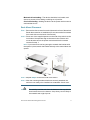
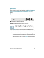
STEP 1 Remove the four screws from each side near the front of the switch.
Retain the screws for re-installation. (Do not remove the four screws
from each side near the back of the switch.)
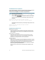
STEP 2 Place one of the supplied spacers on the side of the switch so the
four holes of the spacers align to the screw holes. Place a rack
mount bracket next to the spacer and reinstall the four screws
removed in step 1.
NOTE If your screws are not long enough to reattach the bracket with
the spacer in place, attach the bracket directly to the case without the
spacer.
STEP 3 Repeat Step 2 for the other side of the switch.
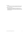
STEP 4 After the mounting hardware has been securely attached, the
switch is now ready to be installed into a standard 19-inch rack.
CAUTION
For stability, load the rack from the bottom to the top, with the
heaviest devices on the bottom. A top-heavy rack is likely to
be unstable and might tip over.
500 Series Stackable Managed Switches
3