1
INVERTER
INVERTER
Plug-in option
INVERTER
FR-A7ND E kit
IB(NA)-0600342ENG-C(1209) MEE
Printed in Japan
Specifications subject to change without notice.
INSTRUCTION MANUAL
HEAD OFFICE: TOKYO BUILDING 2-7-3, MARUNOUCHI, CHIYODA-KU, TOKYO 100-8310, JAPAN
C
FR-A7ND E kit
INSTRUCTION MANUAL
communication function
PRE-OPERATION INSTRUCTIONS
1
INSTALLATION
2
WIRING
3
INVERTER SETTING
4
FUNCTIONS
5
OBJECT MAP DEFINITIONS
6
OBJECT MAP
7
TROUBLESHOOTING
8
Thank you for choosing this Mitsubishi Inverter plug-in option.
This Instruction Manual gives handling information and
precautions for use of this equipment. Incorrect handling might
cause an unexpected fault. Before using the equipment, please
read this manual carefully to use the equipment to its optimum.
Please forward this manual to the end user.
This section is specifically about
safety matters
Do not attempt to install, operate, maintain or inspect this
product until you have read through this Instruction Manual and
appended documents carefully and can use the equipment
correctly. Do not use this product until you have a full
knowledge of the equipment, safety information and
instructions.
In this Instruction Manual, the safety instruction levels are
classified into "WARNING" and "CAUTION".
WARNING
CAUTION
Incorrect handling may cause
hazardous conditions, resulting in
death or severe injury.
Incorrect handling may cause
hazardous conditions, resulting in
medium or slight injury, or may
cause only material damage.
CAUTION level may even lead to a serious
The
consequence according to conditions. Both instruction levels
must be followed because these are important to personal
safety.
SAFETY INSTRUCTIONS
1. Electric Shock Prevention
WARNING
• While the inverter power is ON, do not open the front cover or
the wiring cover. Do not run the inverter with the front cover
or the wiring cover removed. Otherwise you may access the
exposed high voltage terminals or the charging part of the
circuitry and get an electric shock.
• Even if power is OFF, do not remove the front cover except for
wiring or periodic inspection. You may accidentally touch the
charged inverter circuits and get an electric shock.
• Before wiring or inspection, power must be switched OFF. To
confirm that, LED indication of the operation panel must be
checked. (It must be OFF.) Any person who is involved in
wiring or inspection shall wait for at least 10 minutes after the
power supply has been switched OFF and check that there
are no residual voltage using a tester or the like. The
capacitor is charged with high voltage for some time after
power OFF, and it is dangerous.
• Any person who is involved in wiring or inspection of this
equipment shall be fully competent to do the work.
• The plug-in option must be installed before wiring. Otherwise,
you may get an electric shock or be injured.
• Do not touch the plug-in option or handle the cables with wet
hands. Otherwise you may get an electric shock.
• Do not subject the cables to scratches, excessive stress,
heavy loads or pinching. Otherwise you may get an electric
shock.
A-1
2. Injury Prevention
3) Usage
WARNING
CAUTION
• The voltage applied to each terminal must be the ones
specified in the Instruction Manual. Otherwise burst, damage,
etc. may occur.
• The cables must be connected to the correct terminals.
Otherwise burst, damage, etc. may occur.
• Polarity must be correct. Otherwise burst, damage, etc. may
occur.
• While power is ON or for some time after power-OFF, do not
touch the inverter as they will be extremely hot. Doing so can
cause burns.
3. Additional Instructions
Also the following points must be noted to prevent an accidental
failure, injury, electric shock, etc.
• Do not modify the equipment.
• Do not perform parts removal which is not instructed in this
manual. Doing so may lead to fault or damage of the inverter.
CAUTION
• When parameter clear or all parameter clear is performed, the
required parameters must be set again before starting operations
because all parameters return to the initial value.
• Static electricity in your body must be discharged before you
touch the product. Otherwise the product may be damaged.
4) Maintenance, inspection and parts replacement
1) Transportation and mounting
CAUTION
• Do not install or operate the plug-in option if it is damaged or
has parts missing.
• Do not stand or rest heavy objects on the product.
• The mounting orientation must be correct.
• Foreign conductive objects must be prevented from entering
the inverter. That includes screws and metal fragments or
other flammable substances such as oil.
2) Trial run
5) Disposal
CAUTION
• This inverter plug-in option must be treated as industrial
waste.
6) General instruction
CAUTION
• Before starting operation, each parameter must be confirmed
and adjusted. A failure to do so may cause some machines to
make unexpected motions.
A-2
CAUTION
• Do not test the equipment with a megger (measure insulation
resistance).
Many of the diagrams and drawings in this Instruction Manual
show the inverter without a cover or partially open for
explanation. Never operate the inverter in this manner. The
cover must be reinstalled and the instructions in the inverter
manual must be followed when operating the inverter.
⎯ CONTENTS ⎯
1
PRE-OPERATION INSTRUCTIONS
1.1
Unpacking and Product Confirmation .............................................................................................1
1.1.1
1.1.2
1.2
1.3
1.4
2
2.1
2.2
2.3
3
3.1
3.2
4
4.1
4.2
1
SERIAL number.............................................................................................................................................. 1
Product confirmation....................................................................................................................................... 2
Parts ....................................................................................................................................................3
MNS LED (operation status indication) ...........................................................................................4
Specifications.....................................................................................................................................5
INSTALLATION
6
Pre-Installation Instructions .............................................................................................................6
Installation Procedure .......................................................................................................................6
Node Address Setting .....................................................................................................................12
WIRING
14
Connection to Network....................................................................................................................14
Wiring................................................................................................................................................15
INVERTER SETTING
20
Parameter List ..................................................................................................................................20
DeviceNet Data.................................................................................................................................21
I
4.2.1
4.2.2
4.3
Operation Mode Setting ..................................................................................................................25
4.3.1
4.3.2
4.4
5
Operation selection at communication error occurrence (Pr. 500 to Pr. 502) .............................................. 34
Alarm and measures .................................................................................................................................... 38
Inverter Reset ...................................................................................................................................40
Frequency and Speed Conversion Specifications .......................................................................42
FUNCTIONS
5.1
5.2
6
44
Object Model of DeviceNet Communication .................................................................................44
Response Level................................................................................................................................45
6.2.1
6.2.2
6.3
43
Output from the Inverter to the Network........................................................................................43
Input to the Inverter from the Network...........................................................................................43
OBJECT MAP DEFINITIONS
6.1
6.2
II
Communication EEPROM write selection (Pr. 342) .....................................................................................33
Operation at Communication Error Occurrence...........................................................................34
4.5.1
4.5.2
4.6
4.7
Operation mode indication............................................................................................................................ 25
Operation mode switching and communication startup mode (Pr. 79, Pr. 340) ...........................................26
Operation and Speed Command Source (Pr. 338, Pr. 339, Pr. 550) ............................................29
4.4.1
4.5
DeviceNet address (Pr. 345) ........................................................................................................................ 22
DeviceNet baud rate (Pr. 346)...................................................................................................................... 23
Response level of Polling I/O ....................................................................................................................... 45
Response level of explicit message ............................................................................................................. 46
Recommendation for Software Developers ..................................................................................47
7
OBJECT MAP
7.1
Class 0x01 (Identity-Object)............................................................................................................48
7.1.1
7.1.2
7.2
Class 0x2A Instance 1.................................................................................................................................. 70
Class 0x66 (Extended Object I).......................................................................................................79
7.8.1
7.9
Class 0x29 Instance 1 .................................................................................................................................. 68
Class 0x2A (AC Drive Object) .........................................................................................................70
7.7.1
7.8
Class 0x28 Instance 1 .................................................................................................................................. 67
Class 0x29 (Control Supervisor Object) ........................................................................................68
7.6.1
7.7
Class 0x05 Instance 1 Attribute (Explicit message connection) .................................................................. 60
Class 0x05 Instance 2 Attribute (Polling I/O connection) ............................................................................. 62
Class 0x05 Instance 4, 5, 6 Attribute (Explicit message connection) .......................................................... 65
Class 0x05 Instance 1, 2, 4, 5, 6 service...................................................................................................... 66
Class 0x28 (Motor Data Object) ......................................................................................................67
7.5.1
7.6
Output Instance 20/Input Instance 70........................................................................................................... 52
Output Instance 21/Input Instance 71........................................................................................................... 54
Output Instance 126/Input Instance 176....................................................................................................... 56
Class 0x05 (DeviceNet Connection Object)...................................................................................60
7.4.1
7.4.2
7.4.3
7.4.4
7.5
Class 0x03 Instance 1 .................................................................................................................................. 50
Class 0x04 (Assembly Object)........................................................................................................51
7.3.1
7.3.2
7.3.3
7.4
Class 0x01 Instance 0 .................................................................................................................................. 48
Class 0x01 Instance 1 .................................................................................................................................. 49
Class 0x03 (DeviceNet Object) .......................................................................................................50
7.2.1
7.3
48
Class 0x66 Instance 1 .................................................................................................................................. 79
Class 0x67 (Extended Object II)......................................................................................................84
III
7.9.1
Class 0x67 Instance 1 .................................................................................................................................. 84
7.10 Class 0x70 to 0x79 (Extended Object III) .......................................................................................86
7.10.1
Class 0x70 to 0x79 Instance 1, 2 ................................................................................................................. 86
7.11 Class 0x80 (Extended Object IV) ....................................................................................................87
7.11.1
Class 0x80 Instance 1 .................................................................................................................................. 87
7.12 FR-E5ND (FR-E500-KND) Compatible Mode..................................................................................89
8
TROUBLESHOOTING
92
APPENDIX
93
EDS File ............................................................................................................................................93
Error Code List.................................................................................................................................94
IV
1
PRE-OPERATION INSTRUCTIONS
1.1
Unpacking and Product Confirmation
Take the plug-in option out of the package, check the product name, and confirm that the product is as you
ordered and intact.
This product is a plug-in option for the FR-E700 series inverter.
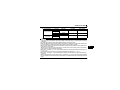
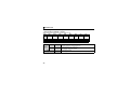
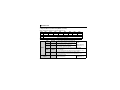
1.1.1
SERIAL number
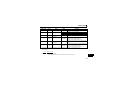
Check the SERIAL number indicated on the rating plate or package.
For the 200V class of FR-E700, this option can be used with the inverter having the following SERIAL
number or later. (For the 400V class of FR-E700, this option can be used with all inverters regardless of
SERIAL number.)
Type
SERIAL number
FR-E720-0.1K to 0.75K
FR-E720-1.5K to 5.5K
FR-E720-7.5K
FR-E720-11K, 15K
J7Y{{{{{{
K7Y{{{{{{
L7Y{{{{{{
G7Y{{{{{{
z SERIAL number check
Refer to the Instruction Manual of the inverter for the location of the rating plate.
Rating plate example
Symbol
7
Year
Y
Month
{{{{{{
Control number
SERIAL (Serial No.)
The SERIAL consists of one symbol, two characters indicating production year and month,
and six characters indicating control number.
The last digit of the production year is indicated as the Year, and the Month is indicated by
1 to 9, X (October), Y (November), or Z (December).
1
1
PRE-OPERATION INSTRUCTIONS
1.1.2
Product confirmation
Check the enclosed items.
Plug-in option
Mounting screw (M3 × 6mm)
Terminal block
.........................................................1 ........................ 2 (Refer to page 8, 10.) ......................... 1 (Refer to page 8, 10.)
78
23
23
78
901
456
901
456
X10
X1
Front cover for plug-in option
Option protective cover
Option small cover (Not used)
.........................................................1 ....................................................... 1* ......................................................... 1
*
Used with the FR-E720-3.7K (FR-E720-175) or less and FR-E740-7.5K (FR-E740-170) or less.
REMARKS
• DeviceNetTM is a registered trademark of ODVA (Open DeviceNet Vender Association, INC).
CAUTION
• In place of the inverter front cover, install a provided front cover for plug-in option.
2
PRE-OPERATION INSTRUCTIONS
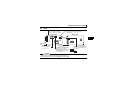
1.2
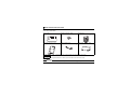
Parts
Connector for communication
Mount the accessory terminal
block to connect to the network.
MNS LED (operation status indication)
Lit/flicker/off of the LED indicate inverter
operation status. (Refer to page 4.)
78
78
456
X1 SW2
ON
456
SW1 X10
SHIELD
23
CAN-
901
1 2
23
V-
901
SW3
Front view
Rear view
LED1
2
1
MNS
FR-A7ND
Mounting
hole
1
SW4
CAN+
V+
Mounting
hole
Mounting hole
1 2
ON
Node address switch
Set the node address.
(Refer to page 12.)
Switch for manufacturer setting
Do not change from initially-set
status (OFF).
SW4
2
L
Connector
Connect to the inverter
option connector.
Compatible mode switch (SW3)
Switch over to the FR-E5ND
(FR-E500-KND) compatible mode.
(Refer to page 89.)
(In the initial status, the switches
1 and 2 are both OFF.)
O
N
CAUTION
• Set the compatible mode switch (SW3) before switching ON the inverter and do not change the setting
while the power is ON. Otherwise you may get an electric shock.
• Do not turn ON the switch 2 of the compatible mode switch (SW3).
3
PRE-OPERATION INSTRUCTIONS
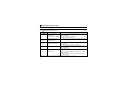
1.3
MNS LED (operation status indication)
The MNS LED indicates the operating status of the option unit by its indication status.
Check the position of LED on page 3.
LED
Indication
Operating Status
Note
· Turn inverter power on. Option unit will then complete duplicate
Inverter power off
station number test.
Off
Network power off
· Check the voltage of the network power.
Own node only on the network
· Add other nodes to the network.
Network and inverter power on The inverter power turns on and duplicate of node address is being
Green
Connection not yet
checked. However, a host has not yet established a communication
(flickering)
established by host
link.
Network and inverter power on A master device on the network has designated the option unit for
Green (lit)
Connection established by
communications.
host
LED holds the state also during communication.
Master designated the option unit for communication on the
Red (flickering) Connection time-out
network, but then sent no messages within the time limit * set in the
expected packet rate.
Check for the followings.
· Duplicate node address on the network
· Cable from option unit to network not connected or severed.
Red (lit)
Critical link failure
· Network damaged
Take the appropriate corrective action, then reset the inverter to
recover from the fault.
* Time limit = 4 × EPR (EPR = Expected Pack Rate Class 0x05 Instance 1 Attribute 9 (refer to page 61))
4
PRE-OPERATION INSTRUCTIONS
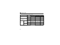
1.4
Specifications
Item
Specifications
Control power
Supplied from the inverter
supply
External power Input voltage: 11 to 28V
input
Consumption current: 90mA maximum
Conforms to ODVA DeviceNet Specification Release 2.0
Standard
(support UCMM)
Network topology
DeviceNet (linear bus with drop lines)
Communication cable
DeviceNet standard thick or thin cable (For a drop cable, use a thin cable.)
500m (125kbps)
Maximum cable length
250m (250kbps)
100m (500kbps)
Communication speed
125kbps, 250kbps, 500kbps
64 (including master)
Number of inverters
The number of inverters connectable is 64 - 1 = 63 when a minimum of one node as a
connected
master is connected.
Response time
Refer to page 45.
Power
supply
1
5
2
INSTALLATION
2.1
Pre-Installation Instructions
Make sure that the input power of the inverter is off.
CAUTION
Do not mount or remove the plug-in option while the power is being input. Otherwise, the
inverter and plug-in option may be damaged.
Static electricity in your body must be discharged before you touch the product. Otherwise the
product may be damaged.
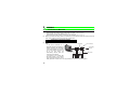
2.2
Installation Procedure
The FR-E700 series has one connection connector for the plug-in option.
CAUTION
•
•
Always perform wiring to the main circuit terminals and control circuit terminals
before installing the option. Wiring cannot be performed after installing the
option.
For wiring to terminals RUN, FU, and SE of control circuit terminal, run cables to
prevent them from being caught between the option board and control circuit
terminal block as shown in the right figure. In case cables are caught, the
inverter may be damaged.
When the inverter cannot recognize that the option unit is mounted due to
improper installation, etc., "
•
•
•
6
Plug-in
option
" (option fault) is displayed.
When mounting/removing an option, hold the sides of the circuit board. Do not
press on the parts on the circuit board. Stress applied to the parts by pressing, etc. may cause a failure.
Take caution not to drop a mounting screw during mounting and removal of the option.
Pull the option straight out when removing. Pressure applied to the connector and to the circuit board may
break the option.
INSTALLATION
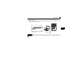
z For FR-E720-3.7K (FR-E720-175) or lower and FR-E740-7.5K (FR-E740-170) or lower
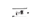
(1) Remove the front cover from the inverter. (For removing the front cover, refer to the FR-E700
instruction manual.)
(2) Remove the PU cover from the front cover. Open the PU cover with a driver, etc. and remove it in the
direction of arrow as shown below.
(1) Front cover
*
2
(2) PU cover
* Open the PU cover, then open it toward the arrow
direction to remove.
REMARKS
• Because the voltage class, model name and serial (only voltage class is written for FR-E740-5.5K (FR-E740-120)
or higher) are stated on the PU cover, replace a PU cover of a plug-in option front cover with the removed PU cover
from the inverter.
7
INSTALLATION
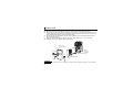
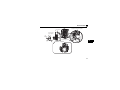
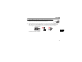
(3) Install the option protective cover.
(4) Securely fit the connector of the plug-in option to the inverter connector along the guides.
(5) Securely fix the both top and bottom of the plug-in option to the inverter with the accessory mounting
screws. (tightening torque 0.33N•m to 0.40N•m) If the screw holes do not line-up, the connector may
not have been plugged snugly. Check for loose plugging.
(6) Remove the PU cover provided on the front cover for plug-in option and install the other PU cover,
which was removed in (2).
(7) Mount the already wired terminal block to the plug-in option. (Refer to the chapter 3 for wiring.)
(8) Install the front cover for plug-in option to the inverter.
Front cover
for plug-in option
(4)
(8)
Option
connector
of inverter
(6) Replace
(3) Option protective cover
(7)
(5)
Mounting screws
REMARKS
•
8
When the option protective cover is not installed, the protective structure (JEM1030) changes to open type (IP00).
INSTALLATION
z For FR-E720-5.5K (FR-E720-240) or higher and FR-E740-11K (FR-E740-230) or higher
(1) Remove the front cover 1 and 2 from the inverter. (For removing the front cover, refer to the FR-E700
instruction manual.)
(2) Remove the PU cover from the front cover 2. For removing the PU cover, refer to page 7.
Front cover 1
Front cover 2
1)
1)
2
2)
PU cover
REMARKS
• Because the voltage class is stated on the PU cover, replace a PU cover of a plug-in option front cover with the
removed PU cover from the inverter.
9
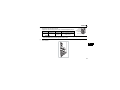
INSTALLATION
(3) Install the front cover 1 to the inverter.
(4) Securely fit the connector of the plug-in option to the inverter connector along the guides.
(5) Securely fix the both top and bottom of the plug-in option to the inverter with the accessory mounting
screws. (tightening torque 0.33N•m to 0.40N•m) If the screw holes do not line-up, the connector may
not have been plugged snugly. Check for loose plugging.
(6) Remove the PU cover provided on the front cover for plug-in option and install the other PU cover,
which was removed in (2).
(7) Mount the already wired terminal block to the plug-in option. (Refer to the chapter 3 for wiring.)
(8) Install the front cover for plug-in option to the inverter.
10
INSTALLATION
(4) Option connector of inverter
Front cover 1
(3)
Front cover for
plug-in option
(6)
(8)
Replace
(5) Mounting screws
2
(7)
Installation completed
11
INSTALLATION
2.3
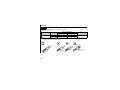
Node Address Setting
(1) Setting with node address switch
Set the node address between "0 to 63" using node address switches on the FR-A7ND (refer to page 3).
The setting is reflected when power turns on next or the inverter is reset.
Set Pr. 345 or Class 0x03 Instance 1 Attribute 1 to "63 (initial value)".
Set the arrow (×) of the corresponding switches to the number to set a desired address.
z Setting example
78
78
78
78
901
456
456
456
X1
901
456
23
X10
Node address 26:
Set the "×" of X10(SW1) to "2" and the
"×" of X1(SW2) to "6".
23
901
23
901
23
Node address 1:
Set the "×" of X10(SW1) to "0" and the
"×" of X1(SW2) to "1".
X10
X1
CAUTION
901
901
23
78
Bad
example
456
78
Good
example
23
456
• Set the inverter node address before switching on the inverter and do not change
the setting while power is on. Otherwise you may get an electric shock.
• Set the node address switch to the switch number position correctly. If the switch
is set between numbers, normal data communication can not be made.
• When the node address switch is set to values other than "0 to 63", they are regarded as "63".
• You cannot set the same node address to other devices on the network. (If different devices have the
same node address, the communication cannot be established properly.)
12
INSTALLATION
(2) Set with parameter (Pr. 345)
Use parameter (Pr. 345) of the inverter to set. Setting node address with parameter makes the node
address setting invalid. The setting is reflected at the next power-on or inverter reset. (Refer to page 22)
(3) Setting with master
Use Class 0x03 Instance 1 Attribute 1 to set from the master. The setting change is reflected to Pr. 345.
Setting node address from the master makes the node address switch setting invalid. (Refer to page 50)
All connections are released and a set value is immediately reflected.
2
13
3
3.1
WIRING
Connection to Network
(1) Be sure to check the following before connecting the inverter to the network.
· Check that the FR-A7ND is snugly inserted into the inverter. (Refer to page 6.)
· Check that the correct node address is set. (Refer to page 12.)
· Check that a drop cable is firmly connected to the FR-A7ND. (Refer to page 15.)
(2) Make sure that the terminating resistor is installed at each end (between CAN+ and CAN-) of the trunk
cable. These resistors must meet the following requirements.
Requirements of Terminating Resistors
R (resistance value) = 121Ω
1% metal film
0.25 W
(3) Connect drop cables to the trank
Trunk cable
Trunk connector
cable.
· If the trunk connector is a
DeviceNet sanctioned pluggable or
Terminating
sealed connector, the connection
resistor
to the active network can be made
at any time whether the inverter is
on or off. The option unit
Drop cable
Inverter
Inverter
automatically detects when the
connection is completed.
· If connecting to the network with
free wires, power to the network
and inverter should be shut off as a
safety precaution in case two or more signal wires are accidentally shorted together.
14
WIRING
3.2
Wiring
(1) Strip the insulation back about 40mm on the free wire end of the drop cable to
expose the four colored signal wires and the silver shield wire.
(2) Strip the insulation back of each signal cable to use. If the length of the sheath pealed is too long, a
short circuit may occur among neighboring wires. If the length is too short, wires might come off.
Wire the stripped cable after twisting it to prevent it from becoming loose. (Do not solder it.)
Cable stripping length
3
7mm
Use a blade type terminal as required.
15
WIRING
REMARKS
Blade terminals available on the market (as of February 2012)
zPhoenix Contact Co.,Ltd
Terminal Screw Size
Cable Size
(mm
2)
0.3 to 0.5
0.5 to 0.75
M3
Blade Terminal Model
With insulation
Without insulation
sleeve
sleeve
Al 0,5-6WH
A 0,5-6
Al 0,75-6GY
A 0,75-6
Crimping Tool Name
CRIMPFOX 6
Insert wires to a blade terminal, and check that the wires come out for about 0 to 0.5 mm from a sleeve.
Check the condition of the blade terminal after crimping. Do not use a blade terminal of which the crimping is
inappropriate, or the face is damaged.
ell
Sh
Sl
ee
ve
m
.5m
o0
0t
16
Unstranded
wires
ire
W
Damaged
Crumpled tip
Wires are not inserted
into the shell
WIRING
(3) Loosen the terminal screw and insert the cable into the terminal
according to the terminal arrignment.
Tighten each cable with fixing screws to the recommended tightening torque.
Screw Size Tightening Torque
M3
0.5N•m to
0.6N•m
Cable Size
Screwdriver
0.3mm2 to
Small flat-blade screwdriver
(Tip thickness: 0.4mm/tip
width: 2.5mm)
0.75mm
2
V- (black)
CAN- (blue)
Shielded cable
CAN+ (white)
V+ (red)
Terminal layout
CAUTION
• Undertightening can cause cable disconnection or malfunction. Overtightening can cause a short
circuit or malfunction due to damage to the screw or unit.
(4) Connect the terminal block to the connector for communication of the communication option mounted
on the inverter.
3
5
9
4
0
123
678
5
678
9
4
0
123
17
WIRING
(5) When wiring the FR-E700 series, if a hook of the front cover of the plug-in option impedes wiring, cut
off the hook and perform wiring.
Cut off with a
nipper, etc.
Cut off a hook at the bottom
of the option cover.
(Cut off so that no portion is left.)
REMARKS
•
18
When the option protective cover is not fitted or wire is not passed through even if the hook of the front cover of the
plug-in option has been cut off, the protective structure (JEM1030) changes to open type (IP00).
WIRING
(6) For wiring of FR-E720-5.5K (FR-E720-240) or higher and FR-E740-11K (FR-E740-230) or higher, pass
a cable on the inverter front cover as shown below. If a drop cable is passed through inside the inverter
front cover, the bending radius of the cable becomes small, stressing the cable.
3
CAUTION
When wiring, take care not to subject the cable to stress.
After wiring, wire offcuts must not be left in the inverter. They may cause a fault, failure or
malfunction.
19
4
INVERTER SETTING
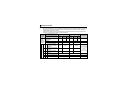
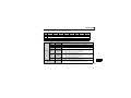
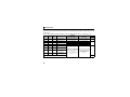
4.1
Parameter List
The following parameters are used for the communication option (FR-A7ND)
Set the values according to need.
Parameter
Number
79
338
339
340
342
345 *1
346 *1
349 *1
500 *1
501 *1
502 *2
550 *2
Name
Operation mode selection
Communication operation command source
Communication speed command source
Communication startup mode selection
Communication EEPROM write selection
DeviceNet address
DeviceNet baud rate
Communication reset selection
Communication error execution waiting time
Communication error occurrence count
display
Stop mode selection at communication error
NET mode operation command source
selection
Setting Range
Minimum
Setting
Increments
Initial
Value
Refer to
Page
0 to 4, 6, 7
0, 1
0, 1, 2
0, 1, 10
0, 1
0 to 4095
0 to 4095
0, 1
0 to 999.8s
1
1
1
1
1
1
1
1
0.1s
0
0
0
0
0
63
132
0
0
26
30
30
26
33
22
23
41
34
0
1
0
35
0, 1, 2, 3
1
0
36
0, 2, 9999
1
9999
29
*1 Parameters which can be displayed when the plug-in option (FR-A7ND) is mounted.
*2 The setting is reflected after inverter reset or at the next power-ON.
20
INVERTER SETTING
4.2
DeviceNet Data
DeviceNet communication startup data can be set with the inverter parameter without using a DeviceNet
configuration tool.
For the setting method with a EDS file (refer to page 93) DeviceNet configuration tool, refer to the
configuration tool manual.
4
21
INVERTER SETTING
4.2.1
DeviceNet address (Pr. 345)
Parameter
Number
345
Name
DeviceNet address
Setting Range
Minimum Setting
Increments
Initial
Value
0 to 4095
1
63
The definition of Pr. 345 is as follows.
Bit15
Bit14
Bit13
Bit12
Bit11
Bit10
Address Key (AKey)
Bit9
Bit8
Bit7
Not Available
Bit6
Bit5
Bit4
Bit3
Bit2
Bit1
Bit0
Device Node Address (Addr)
Communication continuation selection(ResCom)
Bit
0 to 5
11
Item
Device Node
Address (Addr)
Selection of
continuous
communication at
inverter reset
(ResCom)
12 to 15 Address Key (AKey)
22
Initial
Value
63
Setting
Range
0 to 63
Node Address (MAC ID) of device
is set between 0 to 63.
Set "63" (initial value) to set node
address with node address switch.
Node address can be set with
DeviceNet Object Class 0x03,
Instance1, Attribute1. (Refer to
page 50)
0
Reset the option unit in synchronization with the inverter.
When connection is timed out, communication may not resume
according to the master action. In this case, release connection and
reestablish to make communication enabled.
1
The option unit will not be reset even if the inverter is reset and
communication continues.
After inverter reset, preset a value other than "0" in Pr. 340 so that
the inverter starts in network operation mode.
0
Set "0" always. When a value other than "0" is set, the inverter
operates as when "63" (initial value) is set in Pr. 345.
0
0
Definition
INVERTER SETTING
4.2.2
DeviceNet baud rate (Pr. 346)
Parameter
Number
346
Name
Setting Range
Minimum Setting
Increments
Initial
Value
0 to 4095
1
132
DeviceNet baud rate
Set baud rate etc. to start DeviceNet communication.
Bit15
Bit14
Bit13
Bit12
Bit11
Baud Rate Key
Bit
0, 1
Item
Baud Rate (BR)
Bit10
Bit9
Bit8
Bit7
Input Assembly (IA)
Initial
Value
0
2 to 6
Output
Assembly (OA)
1
7 to 11
Input Assembly
(IA)
1
12 to 15 Baud Rate Key
0
Bit6
Bit5
Bit4
Bit3
Output Assembly (OA)
Setting Range
Bit2
Bit1
Bit0
Baud Rate
(BR)
Definition
0, 3
125kbps
1
250kbps
2
500kbps
This value can be set with DeviceNet
Object Class 0x03 Instance 1
Attribute 2. (Refer to page 50)
0
1
6
Other than the above
0
1
6
Other than the above
Output Instance 20 (0x14)
Output Instance 21 (0x15)
· Set the same value for input
Output Instance 126 (0x7E)
assembly and output assembly.
Output Instance 21 (0x15) · The value can be set with Control
Supervisor Class 0x29 Instance 1
Input Instance 70 (0x46)
Attribute 140, 141. (Refer to page
Input Instance 71 (0x47)
69)
Input Instance 176 (0xB0)
Input Instance 71 (0x47)
0
Set "0" always. When a value other than "0" is set, the inverter
operates as when "132" (initial value) is set in Pr. 346.
23
4
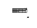
INVERTER SETTING
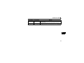
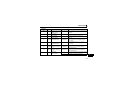
For Pr.346, determine its setting value according to the baud rate and output/input instances.
Output Instance/
Input Instance
20 / 70
21 / 71
126 / 176
0, 3
1
2
132 (Initial value), 135
133
134
792, 795
793
794
Baud Rate
125kbps
250kbps
500kbps
24
INVERTER SETTING
4.3
Operation Mode Setting
The inverter mounted with a communication option has three operation modes.
(1) PU operation [PU].............. Controls the inverter from the key of the operation panel on the inverter or
parameter unit (FR-PU07/FR-PA07).
(2) External operation [EXT] ... Controls the inverter by switching on/off external signals connected to the
control circuit terminals of the inverter.
(The inverter is factory-set to this mode.)
(3) Network operation [NET] ... Controls the inverter with instructions from the network via the
communication option.
(The operation signal and running frequency can be entered from the
control circuit terminals depending on the Pr. 338 Communication operation
command source and Pr. 339 Communication speed command source setting.
Refer to page 30.)
4.3.1
Operation mode indication
4
Operation panel
Operation mode indication
(The inverter operates according to the LED lit mode.)
PU: PU operation mode
EXT: External operation mode
NET: Network operation mode
25
INVERTER SETTING
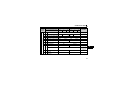
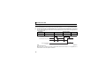
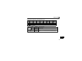
4.3.2
Operation mode switching and communication startup mode (Pr. 79, Pr. 340)
(1) Operation mode switching conditions
Before switching the operation mode, check that:
1) The inverter is at a stop;
2) Both the STF and STR signals are off; and
3) The Pr. 79 Operation mode selection setting is correct.
(Set using the operation panel of the inverter or parameter unit (FR-PU07/FR-PA07).)
Refer to the Instruction Manual of the inverter for details of Pr. 79.
(2) Operation mode selection at power on and at restoration from instantaneous power failure
The operation mode at power on and at restoration from instantaneous power failure can be selected.
Set a value other than "0" in Pr. 340 to select the network operation mode.
After started in network operation mode, parameter write from the network is enabled.
REMARKS
• Changes of the Pr. 340 setting become valid at powering on or resetting the inverter.
• Pr. 340 can be changed with the operation panel independently of the operation mode.
26
INVERTER SETTING
Pr. 340
Setting
Pr. 79
Setting
Operation Mode at Power on or Power
Restoration
Operation Mode Switchover
0 (initial
value)
1
Switching among the external, PU, and NET operation mode is
External operation mode
enabled *1
PU operation mode
PU operation mode fixed
Switching between the external and Net operation mode is enabled
2
External operation mode
0
Switching to the PU operation mode is disallowed
3, 4
External/PU combined operation mode
Operation mode switching is disallowed
(initial
Switching among the external, PU, and NET operation mode is
value)
6
External operation mode
enabled while running.
X12 (MRS) signal ON ..... external operation mode Switching among the external, PU, and NET operation mode is enabled *1
7
operation mode fixed (Forcibly switched to external
X12 (MRS) signal OFF ... external operation mode External
operation mode.)
0
NET operation mode
1
PU operation mode
2
NET operation mode
Same as when Pr. 340 = "0"
3, 4
External/PU combined operation mode
1
NET operation mode
6
X12 (MRS) signal ON .... NET operation mode
7
X12 (MRS) signal OFF ... external operation mode
0
NET operation mode
Switching between the PU and NET operation mode is enabled *2
1
PU operation mode
Same as when Pr. 340 = "0"
NET operation mode
NET operation mode fixed
2
10
3, 4
External/PU combined operation mode
Same as when Pr. 340 = "0"
Switching between the PU and NET operation mode is enabled while
6
NET operation mode
running *2
7
External operation mode
Same as when Pr. 340 = "0"
*1 Operation mode can not be directly changed between the PU operation mode and network operation mode.
*2 Operation mode can be changed between the PU operation mode and network operation mode with
of the operation panel and
X65 signal.
27
4
INVERTER SETTING
(3) Operation mode switching method
External operation
When "0 or 1" is set in Pr. 340
Switching with the PU
Switching through the network
Switch to external
operation mode through
the network.
Switch to network operation
mode through the network.
Press
on
the PU to light
Press
on
the PU to light
Network operation
When "10" is set in Pr. 340
PU operation
Press
on the PU to light
Network operation
PU operation
Press
on the PU to light
For the switching method with the external terminal, refer to the Instruction Manual of the inverter.
Refer to page 73 for a switching method through the network.
CAUTION
• When starting the inverter in network operation mode at power-ON or an inverter reset, set a value other
than 0 in Pr. 340. (Refer to page 26)
• When setting a value other than 0 in Pr. 340, make sure that the initial settings of the inverter are correct.
28
INVERTER SETTING
4.4
Operation and Speed Command Source (Pr. 338, Pr. 339, Pr. 550)
(1) Select control source for the network operation mode (Pr. 550)
A control location for the network operation mode can be selected from either the RS-485
communication with the PU connector or communication option.
When using a communication option, set "0 or 9999 (initial value)" in Pr. 550.
Parameter
Number
Name
Initial Value
Setting
Range
0
2
550
NET mode operation
command source selection
9999
9999
Description
Selects the communication option as
NET operation mode command
source.
Selects the PU connector as the NET
operation mode command source.
Automatic communication option
recognition
Normally, PU connector is the
command source. When a
communication option is mounted,
the communication option is the
command source.
Refer to the Instruction Manual of the inverter for details.
29
4
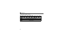
INVERTER SETTING
(2) Selection of control source for the network operation mode (Pr. 338, Pr. 339)
⋅ As control sources, there are the operation command source that controls the signals related to the
inverter start command and function selection and the speed command source that controls the
signals related to frequency setting.
⋅ In network operation mode, the commands from the external terminals and communication (PU
connector or communication option) are as listed below.
Operation Pr. 338 Communication operation
command source
Location
Pr. 339 Communication speed
Selection
command source
Fixed
function
(terminalequivalent
function)
Pr. 178 to Pr. 184 setting
Selective function
0
1
2
3
4
5
30
Running frequency from
communication
Terminal 2
Terminal 4
Low-speed operation
command/remote setting
RL
clear/stop-on contact
selection 0
Middle-speed operation
RM command/remote setting
function
High-speed operation
RH command/remote setting
function
Second function selection/
RT
stop-on contact selection 1
AU Terminal 4 input selection
JOG Jog operation selection
0: NET
0:
NET
1:
1: External
2:
External External
0:
NET
1:
2:
External External
NET
—
NET
NET
—
NET
—
External
—
—
External
—
—
External
—
External
NET
External
NET
External
NET
External
NET
External
NET
External
NET
External
NET
—
Combined
—
External
—
Remarks
Combined
External
Pr. 59 = "0"
(multi-speed)
Pr. 59 = "1, 2"
(remote)
Pr. 270 = "1"
(stop-on-contact)
Pr. 270 = "1"
(stop-on-contact)
INVERTER SETTING
Operation Pr. 338 Communication operation
command source
Location
Pr. 339 Communication speed
Selection
command source
OH
8
REX 15-speed selection
10
X10 Inverter run enable signal
PU operation external
X12
interlock
X14 PID control valid terminal
Brake opening completion
BRI
signal
PU-External operation
X16
switchover
X18 V/F switchover
Output stop
Pr. 178 to Pr. 184 setting
Selective function
14
15
16
18
24 MRS
NET
1:
2:
External External
0:
NET
1:
2:
Remarks
External External
External
NET
External
NET
External
Pr. 59 = "0"
(multi-speed)
External
External
NET
External
NET
NET
External
External
External
NET
Combined
PU operation interlock
Start self-holding
selection
Forward rotation
60 STF
command
25 STOP
0:
1: External
External thermal relay
input
7
12
0: NET
External
External
External
—
External
NET
External
Pr. 79 ≠ "7"
Pr. 79 = "7"
When the X12
signal is not
assigned
31
4
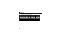
INVERTER SETTING
Pr. 178 to Pr. 184 setting
Selective function
Operation Pr. 338 Communication operation
command source
Location
Pr. 339 Communication speed
Selection
command source
61 STR
62 RES
65
X65
66
X66
67
X67
Reverse rotation
command
Inverter reset
PU/NET operation
switchover
External/NET operation
switchover
Command source
switchover
0: NET
0:
NET
1:
1: External
2:
External External
0:
NET
NET
1:
2:
Remarks
External External
External
External
External
External
External
[Explanation of table]
External
: Command is valid only from control terminal.
NET
: Command only from communication is valid
Combined : Command from both control terminal and communication is valid.
—
: Command from either of control terminal and communication is invalid.
REMARKS
• The command source of communication is as set in Pr. 550 and Pr. 551.
• The Pr. 338 and Pr. 339 settings can be changed while the inverter is running when Pr. 77 = "2". Note that the setting
change is reflected after the inverter has stopped. Until the inverter has stopped, communication operation
command source and communication speed command source before the setting change are valid.
32
INVERTER SETTING
4.4.1
Communication EEPROM write selection (Pr. 342)
When parameter write is performed from the communication option, write to RAM is enabled. Set when
frequent parameter changes are necessary.
Parameter
Number
342
Name
Communication EEPROM write
selection
Initial
Value
Setting
Range
0
0
1
Description
Parameter values written by
communication are written to the
EEPROM and RAM.
Parameter values written by
communication are written to the RAM.
⋅ When changing the parameter values frequently, set "1" in Pr. 342 to write them to the RAM.
Performing frequent parameter write with "0 (initial value)" (EEPROM write) set will shorten the life of the
EEPROM.
REMARKS
• When "1" (write to RAM only) is set in Pr. 342, powering off the inverter will erase the changed parameter values.
Therefore, the parameter values available when power is switched on again are the values stored in EEPROM
previously.
33
4
INVERTER SETTING
4.5
Operation at Communication Error Occurrence
4.5.1
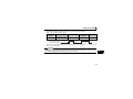
Operation selection at communication error occurrence (Pr. 500 to Pr. 502)
You can select operations at communication error occurrences by setting Pr. 500 to Pr. 502 under network operation.
(1) The set time from when a communication line error occurrence until communication error output
You can set the waiting time from when a communication line error occurs until it is recognized as a
communication error.
Parameter
Number
Name
Setting Range
Minimum Setting
Increments
Initial Value
500
Communication error
execution waiting time
0 to 999.8s
0.1s
0
Communication line status
Normal
Error
Normal
Error
Recognition
Communication error (E.OP1)
Pr. 500
setting time
Minor fault signal(LF)
(Pr. 502 = 3)
Pr. 500
setting time
ON
If the communication line error still persists after the time set in Pr. 500 has elapsed, it is recognized as
a communication error.
When the error is restored to normal communication within the set time, it is not regarded as a
communication error and operation continues.
34
INVERTER SETTING
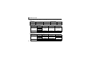
(2) Display and erasure of communication error occurrence count
The cumulative number of communication error occurrences can be indicated.
Write "0" to erase this cumulative count.
Parameter
Number
Name
Setting Range
Minimum Setting
Increments
Initial Value
501
Communication error
occurrence count display
0
1
0
Count timing depending on
communication line status
Normal
Error
Normal
Incremented by 1
Error
Incremented by 1
At the point of communication line error occurrence, Pr. 501 Communication error occurrence count
display is incremented by 1.
CAUTION
• The communication error count occurrence is stored into RAM temporarily. Since this data is stored in
EEPROM at one-hour intervals, performing power-on reset or inverter may cause the Pr. 501 data to be the
value stored in EEPROM the last time depending on the reset timing.
35
4
INVERTER SETTING
(3) Inverter operation selection at communication error occurrence
You can select the inverter operation if a communication line error or an error of the option unit itself
occurs.
Parameter
Number
Name
Setting Range
Minimum Setting
Increments
Initial Value
502
Stop mode selection at
communication error
0, 1, 2, 3
1
0
About setting
z Operation at error occurrence
Alarm Definition
Pr. 502 Setting
Operation
Indication
Alarm Output
Communication line
0
1
2
3
Continued *
Normal indication *
Not provided *
Communication
option itself
0, 3
1, 2
Coast to stop
Decelerated to stop
E. 1 lit
E. 1 lit after stop
Provided
Provided after stop
* When the error returns to normal communication within the time set in Pr. 500, it is not regarded as a communication line
error (E.OP1).
z Operation at error recognition after elapse of Pr. 500 time
Alarm Definition
Communication line
Communication
option itself
36
Pr. 502 Setting
Operation
Indication
Alarm Output
0
1
2
3
0, 3
1, 2
Coast to stop
E.OP1 lit
Decelerated to stop
E.OP1 lit after stop
Provided
Provided after stop
Continued
Coast to stop
Decelerated to stop
Normal indication
E. 1 lit
E. 1 lit after stop
Not provided
Provided
Provided after stop
INVERTER SETTING
z Operation at error removal
Alarm Definition
Pr. 502 Setting
Communication line
0
1
2
3
Communication
option itself
0, 3
1, 2
Operation
Indication
Alarm Output
Kept stopped
E.OP1 kept lit
Kept provided
Restart
Continued
Normal indication
Not provided
Kept stopped
E. 1 kept lit
Kept provided
CAUTION
• A communication line error [E.OP1 (alarm data: HA1)] is an error that occurs on the communication line,
and an error of the communication option unit itself [E. 1 (alarm data: HF1)] is a communication circuit error
in the option.
• The alarm output indicates alarm output signal (ALM signal) or alarm bit output.
• When the setting was made to provide an alarm output, the error definition is stored into the alarm history.
(The error definition is written to the alarm history when an alarm output is provided.)
When no alarm output is provided, the error definition overwrites the alarm indication of the alarm history
temporarily, but is not stored.
After the error is removed, the alarm indication is reset and returns to the ordinary monitor, and the alarm
history returns to the preceding alarm indication.
• When the Pr. 502 setting is "1" or "2", the deceleration time is the ordinary deceleration time setting (e.g. Pr.
8, Pr. 44, Pr. 45).
• The acceleration time at a restart is the ordinary acceleration time setting (e.g. Pr. 7, Pr. 44).
• When the Pr. 502 setting is "2", the operation/speed command at a restart is the one given before the error
occurrence.
• When a communication line error occurs at the Pr. 502 setting of "2", removing the error during deceleration
causes acceleration to restart at that point. (Acceleration is not restarted if the error is that of the option unit
itself.)
37
4
INVERTER SETTING
4.5.2
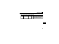
Alarm and measures
(1) The inverter operates as follows at alarm occurrences.
Alarm Location
Status
Inverter
operation
Inverter
Data
communication
Inverter
operation
Communication line
Data
communication
Communication Inverter
operation
option
connection
Data
communication
Communication error
option
Inverter
Error of
operation
communication
Data
option itself
communication
* Depends on the Pr. 502 setting.
38
Network Operation
Operation Mode
External Operation
PU Operation
Inverter trip
Inverter trip
Inverter trip
Continued
Continued
Continued
Inverter trip *
Continued
Continued
Stop
Stop
Stop
Inverter trip *
Inverter trip *
Inverter trip *
Continued
Continued
Continued
Inverter trip *
Continued
Continued
Stop
Stop
Stop
INVERTER SETTING
(2) Measures at alarm occurrences
Alarm Indication
Alarm Definition
E.OP1
Communication line
error
E.1
Option alarm
Measures
Check the LED status of the option unit and remove the cause of the
alarm. (Refer to page 4 for LED indication status)
Inspect the master.
Check the connection between the inverter and option unit for poor
contact, etc. and remove the cause of the error.
When alarms other than the above are displayed, refer to the Instruction Manual of the inverter and remove
the cause of the alarm.
4
39
INVERTER SETTING
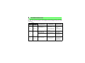
4.6
Inverter Reset
(1) Operation conditions of inverter reset
Which resetting method is allowed or not allowed in each operation mode is described below.
Resetting Method
Inverter reset (Class 0x2A Instance 1 Attribute 101)
Reset from the (Refer to page 72) *1
Pr.349 = 0
network
Error reset at inverter fault
(Refer to page 52) *2
Pr.349 = 1
Network
Operation
Allowed
Allowed
Turn on the inverter terminal RES (RES signal)
Enabled
Switch off inverter power
Enabled
Reset from the Inverter reset
Enabled
PU/operation
Reset at inverter fault
Enabled
panel
*1 Inverter reset can be made any time.
*2 Reset can be made only when the protective function of the inverter is activated.
Operation Mode
External
PU
Operation
Operation
Disallowed
Disallowed
Allowed
Disallowed
Enabled
Enabled
Allowed
Disallowed
Enabled
Enabled
Enabled
Enabled
Enabled
Enabled
CAUTION
• When a communication line error has occurred, reset cannot be made from the network.
• In the initial status, the inverter is set to the External operation mode when it has been reset in Network operation mode.
To resume the network operation, the inverter must be switched to the network operation mode again.
Set a value other than "0" in Pr. 340 to start in network operation mode. (Refer to page 26.)
• The inverter can not be controlled for about 1s after release of a reset command .
40
INVERTER SETTING
(2) Error reset operation selection at inverter fault
When used with the communication option, an error reset command* from network can be made
invalid in the External operation mode or PU operation mode.
Parameter
Number
349
Name
Communication reset
selection
Initial
Value
Setting
Range
0
0
1
Function
Error reset is enabled independently of operation
mode
Error reset is enabled only in the network
operation mode
* Class 0x04 Attribute 3 Instance 20, 21, 126 Byte0 Bit2 (Refer to pages 52, 54, 57.)
4
41
INVERTER SETTING
4.7
Frequency and Speed Conversion Specifications
For frequency setting and monitoring from FR-A7ND, frequency is set in 0.01Hz increments and displayed
on the monitor regardless of the Pr. 37 Speed display setting.
Speed setting and monitor values from FR-A7ND are calculated by the following formula.
Speed setting, monitor (1r/min increments) = frequency × 120 / number of motor poles (4*)
* Calculated on the assumption that the number of motor poles is 4.
REMARKS
• Refer to the Instruction Manual of the inverter for details of Pr. 37.
42
5
5.1
FUNCTIONS
Output from the Inverter to the Network
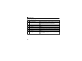
Main items to be output from the inverter (FR-A7ND) to the network and their descriptions are explained below.
Item
Inverter monitor
Operation mode read
Parameter read
Inverter status
Alarm definition
Description
Monitor various items such as inverter output frequency and output current.
Read the operation mode of the inverter.
Read parameter settings of the inverter.
Monitor the output signal of the inverter.
Monitor the alarm history of the inverter.
Refer to Page
78, 87
73
79, 84, 86
74
73
REMARKS
• Refer to the Instruction Manual of the inverter for functions controllable from the network in each operation mode.
5.2
Input to the Inverter from the Network
Main items which can be commanded from the network to the inverter and their descriptions are explained below.
Item
Description
Frequency setting
Set the running frequency of the inverter.
Operation mode write Set the operation mode of the inverter.
Set the control input command such as forward operation signal (STF) and
Run command
reverse rotation signal (STR).
Inverter reset
Reset the inverter.
Parameter write
Set parameters of the inverter.
Parameter clear
Return parameters to the initial values.
Refer to Page
52, 72
73
5
52, 73
49, 72
79, 84, 86
49, 72
REMARKS
• Refer to the Instruction Manual of the inverter for functions controllable from the network in each operation mode.
43
6
OBJECT MAP DEFINITIONS
6.1
Object Model of DeviceNet Communication
For DeviceNet communication, each node is modeled as collections of objects (abstraction of particular
functions of the products).
The following four terms are used to describe object.
Item
Class
Instance
Attribute
Service
Description
Collections of all objects which have same types of functions.
Generalization of object
Concrete expression of object
Expression of object characteristic
Function supported by object or class
The following explains object definitions for use of the FR-A7ND DeviceNet.
For details of the definitions, consult the DeveiceNet documentation available from ODVA.
Class
0x01
0x03
0x04
0x05
0x28
0x29
0x2A
Object Name
Identity Object
DeviceNet Object
Assembly Object
DeviceNet Connection Object
Motor Data Object
Control Management Object
AC Drive Object
In the following tables, Get and Set mean:
Get :Read from inverter
Set :Read from inverter
44
Page
Class
48
50
51
60
67
68
70
0x66
0x67
0x70 to 0x79
0x80
Object Name
Extended Object I
Extended Object II
Extended Object III
Extended Object IV
Page
79
84
86
87
OBJECT MAP DEFINITIONS
6.2
Response Level
6.2.1
Response level of Polling I/O
(1) Response level of DeviceNet bus
Request
Response
Within 1ms
(2) Reflect timing on the actual speed or speed monitor after speed setting
Speed
command
Speed
command B
Speed
command B
Speed monitor
Speed A
Inverter
Speed A
Speed
command B
Speed A
Speed
command B
Speed A
Speed B
Speed B
Within 30ms
6
45
OBJECT MAP DEFINITIONS
6.2.2
Response level of explicit message
(1) Reading
Request
Response
Within 50ms
(2) Writing
Request
Response
Within 50ms
(3) Parameter clearing
The inverter will not respond until parameter clear processing complete (about 5s) after sending
parameter all clear command.
46
OBJECT MAP DEFINITIONS
6.3
Recommendation for Software Developers
Please note the followings when developing designing.
(1) After sending request to the FR-A7ND, wait for response from the FR-A7ND, then send the next
request.
(2) Set waiting time between each message based on FR-A7ND response time on page 45.
For example, after sending a writing request by Explicit message, wait for more than 50ms, then send
the next request.
6
47
7
OBJECT MAP
7.1
Class 0x01 (Identity-Object)
7.1.1
Class 0x01 Instance 0
(1) Attribute
Attribute ID
Access
1
2
6
7
Get
Get
Get
Get
Description
Revision
Maximum Instance
Max Class Attributes
Max Instance Attributes
(2) Service
Service Code
0x0E
48
Description
Get Attribute Single
Data
Length
Attribute Value
Word
Word
Word
Word
1
1
7
7
OBJECT MAP
7.1.2
Class 0x01 Instance 1
(1) Attribute
*1
*2
*3
Attribute ID
Access
1
2
3
4
5
Get
Get
Get
Get
Get
Data
Length
Description
Attribute Value
Vendor ID (Mitsubishi electric)
Device Type (AC drive)
Product Code
Revision
Status
Word
161
Word
02
Word
49
Struct
1.YYY *1
*2
Word
Double
6
Get
Serial Number
xxxxxxxx
Word
7
Get
Product Name (FR-E700)
5 Byte
E700 *3
High byte of hexadecimal word data means integer and low byte means decimal.
For example, when the read data is 0x010A, it means version 1.010.
Bit definition
Bit0: 0 = allocated, 1 = not allocated, Bit2: 0, Bit8: 1 = minor fault occurrence, Bit9: 0, Bit10: 1 = LED is flickering
red, Bit11: 1 = LED is lit red
As the actual data, 0x04, 0x45, 0x37, 0x30, and 0x30 are stored. 0x04 means 4 byte data and the rest means
ASCII code of "E700".
(2) Service
Service Code
Symbol
Name
Setting Range
Description
0
*1
*2
Inverter reset *2
Inverter reset after all parameter
0x05
Reset
Reset *1
1
clear *2
0x0E
Get
Get_Attribute_Single
⎯
Get Attribute Single
As set in Pr. 75. Refer to the Instruction Manual of the inverter for details of Pr. 75.
If the inverter does not accept the command, neither inverter reset nor all parameter clear will be performed.
7
49
OBJECT MAP
7.2
Class 0x03 (DeviceNet Object)
7.2.1
Class 0x03 Instance 1
(1) Attribute
Attribute ID
Access
1
Get/Set
MAC ID *1
Name
Initial Value
*2
2
Get/Set
Baud Rate *1
00
Description
00 to 63: Node address value
00: 125kbps, 01: 250kbps,
02: 500kbps
Allocation Information
5
Get
Allocation Choice Byte
Master's MAC ID
8
*1
*2
Get
MAC ID Switch Value
00
0: G2Explicit, 1: Poll, 2: Bit Strobe,
3: Multicast Poll, 4: Change Of State,
5: Cyclic
0 to 63, 255:
Changed with Allocate only.
00 to 63: Node address switch value
Can be read with Class 0x67 Instance 1 Attribute 45 and 46 also. (Refer to page 84.)
The initial value differs according to the node address switch conditions.
(2) Service
Service Code
0x0E
0x10
0x4B
0x4C
50
Service
Get Attribute Single
Set Attribute Single
Allocate
Release
OBJECT MAP
7.3
Class 0x04 (Assembly Object)
Attribute ID
Access
Name
3
Get
Data
Initial Value Data Length
⎯
Description
Byte alignment Refer to page 52 or later.
Set I/O instance in either of the following methods.
y Pr.346 setting (Refer to page 23)
y Class 0x29, Instance 1, Attribute 140, 141 setting (Refer to page 69)
Output Instance
Input Instance
Refer to page
20 (4 byte)
21 (4 byte)
126 (6 byte)
70 (4 byte)
71 (4 byte)
176 (6 byte)
52
54
56
* Value in parenthesis is data length.
7
51
OBJECT MAP
7.3.1
Output Instance 20/Input Instance 70
1. Output Instance 20 (Master→inverter)
When using Output Instance 20, set Input Instance to 70.
Byte
Bit7
⎯
0
Bit6
⎯
Bit5
⎯
Bit4
⎯
Bit3
Bit2
Bit1
Bit0
⎯
Fault
Reset
⎯
Run Fwd
⎯
Speed reference (low byte)
Speed reference (high byte)
1
2
3
[Output Instance 20 details]
Bit0
Run Fwd
Bit2
Fault Reset
Byte0
Byte2
Byte3
52
Speed Ref
Forward rotation signal
(0:forward rotation off, 1:forward rotation on)
Reset request at an error occurrence
Valid only at in inverter trip
(0:no function, 1:fault reset request)
Speed reference (r/min)
(Refer to page 42 for conversion formula of speed and frequency. )
OBJECT MAP
2. Input Instance 70 (Inverter→master)
When using Input Instance 70, set Output Instance to 20.
Byte
Bit7
⎯
0
Bit6
Bit5
⎯
⎯
1
2
3
Bit4
⎯
Bit3
Bit2
Bit1
Bit0
⎯
Running
Fwd
⎯
Faulted
00
Speed actual (low byte)
Speed actual (high byte)
[Input Instance 70 details]
Bit0
Byte0
Bit2
Byte2
Byte3
Faulted
Running
Fwd
Speed
Actual
Inverter error signal
(0: inverter is under normal operation, 1: inverter is in a fault state)
Forward rotation
(0: other than forward rotation, 1: forward rotation)
Actual speed currently operating (r/min)
(Refer to page 42 for conversion formula of speed and frequency. )
7
53
OBJECT MAP
7.3.2
Output Instance 21/Input Instance 71
1. Output Instance 21 (initial value) (Master→inverter)
When using Output Instance 21, set Input Instance to 71.
Byte
Bit7
⎯
0
Bit6
Net Ref
Bit5
Net Ctrl
Bit4
⎯
Bit3
Bit2
Bit1
Bit0
⎯
Fault
Reset
Run Rev
Run Fwd
⎯
Speed reference (low byte)
Speed reference (high byte)
1
2
3
[Output Instance 21 details]
Bit0
Bit1
Bit2
Byte0
Bit5
Bit6
Byte2
Byte3
54
Forward rotation signal (0: forward rotation off,
1: forward rotation on)
Control related
Reverse rotation signal (0: reverse rotation off, signals
Run Rev
1: reverse rotation on)
Makes valid when
Reset request at an error occurrence
NetCtrl (Bit5) = "1"
Fault Reset Valid only at an inverter trip
(0:no function, 1:fault reset request)
Request permission bit of control related signals (Bit0 to Bit2)
0: Control related signals are invalid (It will not function even if a value is
NetCtrl
set in each bit.).
1: Control related signals are valid (it will not be reflected to Pr. 338).
Request permission bit of speed reference (Byte2, Byte3)
0: Speed related data is invalid (it will not function even if a value is set).
NetRef
1: Speed related data is valid (it will not be reflected to Pr. 339).
Speed reference (r/min)
Makes valid when
Speed Ref (Refer to page 42 for conversion formula of
NetRef (Bit6) = "1"
speed and frequency.)
Run Fwd
OBJECT MAP
2. Input Instance 71 (initial value) (Inverter→master)
When using Input Instance 71, set Output Instance to 21.
Byte
Bit7
Bit6
Bit5
0
At
Reference
Ref From
Net
Ctrl From
Net
Bit4
Bit3
Bit2
Bit1
Bit0
Ready
Running
Rev
Running
Fwd
⎯
Faulted
1
00
2
Speed actual (low byte)
3
Speed actual (high byte)
[Input Instance 71 details]
Byte0
Faulted
Bit2
Running Fwd
Forward rotation (0: other than forward rotation, 1: forward rotation)
Bit3
Running Rev
Reverse rotation (0: other than reverse rotation, 1: reverse rotation)
Bit4
Ready
Ready signal (0: operation preparation, 1: operation ready)
(Always "1" after power on)
CtrlFromNet
State of operation command source (Run/Stop)
(Same definition with Class 0x29 Instance 1 Attribute 15 Refer to page 69)
0: Command is enabled in operation other than network
1: Command is enabled in network operation
Bit6
RefFromNet
State of speed command source
(Same definition with Class 0x2A Instance 1 Attribute 29 Refer to page 71)
0: Command is enabled in operation other than network
1: Command is enabled in network operation
Bit7
AtReference
Up-to-frequency signal (SU signal)
(Same definition with Class 0x2A Instance 1 Attribute 3 Refer to page 70)
Speed Actual
Actual speed currently operating (r/min)
(Refer to page 42 for conversion formula of speed and frequency.)
Bit5
Byte2
Byte3
Inverter error signal
(0:inverter is under normal operation 1: inverter is in a fault state)
Bit0
7
55
OBJECT MAP
7.3.3
Output Instance 126/Input Instance 176
1. Output Instance 126 (Master→inverter)
When using Output Instance 126, set Input Instance to 176.
Byte
Bit7
0
Write
Param
1
2
3
4
5
56
Bit6
Net Ref
Bit5
Net Ctrl
Bit4
⎯
Bit3
Bit2
Bit1
Bit0
⎯
Fault
Reset
Run Rev
Run Fwd
Parameter Instance No.
Speed reference or parameter write data (low byte)
Speed reference or parameter write data (high byte)
Parameter class ID
Parameter attribute ID
OBJECT MAP
[Output Instance 126 details]
Byte0
Bit0
Bit1
Run Fwd
Run Rev
Bit2
Fault Reset
Bit5
NetCtrl
Bit6
NetRef
Bit7
Write Param
Byte1
Byte2
Byte3
Byte4
Byte5
Parameter
Instance No.
Speed Ref or
Parameter Write
Data
Parameter
Class ID
Parameter
Attribute ID
Forward rotation signal (0: forward rotation off, 1: forward rotation on) Control related
Reverse rotation signal (0: reverse rotation off, 1: reverse rotation on) signals
Reset request at an error occurrence
Makes valid when
Valid only at in inverter trip
NetCtrl (Bit5) = "1"
(0:no function, 1:fault reset request)
Request permission bit of control related signals (Bit0 to Bit2)
0: Control related signals are invalid (It will not function even if a value is set in each bit.)
1: Control related signals are valid (It will not be reflected to Pr. 338.)
Request permission bit of speed reference (Byte 2, Byte 3)
0: Speed setting value (Byte 2, 3) is invalid (It will not function even if a value is set.)
1: Speed setting value (Byte 2, 3) is valid (It will not refflected to Pr. 339.)
Request permission bit of speed reference or parameter write (Byte 2, Byte 3)
0: Byte 2, 3 are speed reference
1: Byte 2, 3 are written to parameter write data (It is written to parameter class and attribute
set with Byte 4, 5.)
Parameter Instance No. can be specified.
When 00 is specified, instance No. is regarded as "1".
Speed reference (r/min) or parameter write data
Selection conditions are determined according to a
combination of "NetRef (Bit6)" and "WriteParam
(Bit7)".
[When speed reference is selected]
Refer to page 42 for conversion formula of speed
and frequency.
Write
Param
Net
Ref
0
0
1
1
0
1
0
1
Selected Data
⎯
Speed reference
Parameter write
data
Class ID to access to the inverter parameter (class 0x2A, 0x66, 0x67 etc.)
7
Attribute ID to access to the inverter parameter
57
OBJECT MAP
2. Input Instance 176 (Inverter→master)
When Input Instance 176 is used, 16 bit parameter data is provided.
When using Input Instance 176, set Output Instance to 126.
Byte
0
1
2
3
4
5
58
Bit7
At
Reference
PrEnd
Bit6
Ref From
Net
Bit5
Ctrl From
Net
Bit4
Ready
Bit3
Running
Rev
Bit2
Bit1
Bit0
Running
Fwd
Run
command
mode
Faulted
00
Speed actual (low byte)
Speed actual (high byte)
Parameter read data (low byte)
Parameter read data (high byte)
OBJECT MAP
[Input Instance 176 details]
Bit0
Faulted
Bit2
Bit3
Run Command
Mode *
Running Fwd
Running Rev
Bit4
Ready
Bit5
CtrlFromNet
Bit6
RefFromNet
Bit7
AtReference
Bit7
PrEnd
Bit1
Byte0
Byte1
Byte2
Byte3
Byte4
Byte5
Speed Actual
Parameter
Read Data
Inverter error signal
(0: inverter is under normal operation, 1: inverter is in a fault state)
0: Command is disabled in network operation
1: Command is enabled in network operation
Forward rotation (0: other than forward rotation, 1: forward rotation)
Reverse rotation (0: other than reverse rotation, 1: reverse rotation)
Ready signal (0: operation preparation, 1: operation ready)
(Always "1" after power on)
State of operation command source (Run/Stop)
(Same definition with Class 0x29 Instance 1 Attribute 15 Refer to page 69)
0: Command is enabled in operation other than network
1: Command is enabled in network operation
State of speed command source
(Same definition with Class 0x2A Instance 1 Attribute 29 Refer to page 71)
0: Command is enabled in operation other than network
1: Command is enabled in network operation
Up-to-frequency signal (SU signal)
(Same definition with Class 0x2A Instance 1 Attribute 3 Refer to page 70)
Parameter write is completed
0: Parameter write is not performed
1: During parameter write processing (during inverter processing)
(This bit may change to 1 during Explicit message processing.)
Actual speed currently operating (r/min)
(Refer to page 42 for conversion formula of speed and frequency.)
Parameter write data specified by parameter class ID and parameter attribute ID of output
instance 126 is read. (Refer to page 57)
*Bit status in the run command mode is as follows. (For the operation/speed command source, refer to page 30.)
Inverter Status
Operation Mode
Pr. 338
NET
Other than NET
Pr. 339
Run Command Mode
0: NET
0: NET
1
0: NET
1: External
1: External
⎯
1: External
0: NET
1: External
⎯
0
7
59
OBJECT MAP
7.4
Class 0x05 (DeviceNet Connection Object)
FR-A7ND supports only Polling I/O and Explicit message, not Bit-Strobed I/O. In addition, Instance 4 to 6
are Explicit message Instance.
7.4.1
Class 0x05 Instance 1 Attribute (Explicit message connection)
Class 0x05 Instance 1
Attribute ID
Access
60
Name
Range
Definition
Non-existent
Established
Deferred Delete
Explicit message connection
0x83: Server Transport Class 3
(Example) 0x0740
Group 3 Explicit response message of Slave
Source MAC ID = 0
The value to be specified in the CAN Identifier Field when
this connection transmits
(Example) 0x0780
Group 3 Explicit request message of Master
Destination MAC ID = 0
The value distinguishes the received messages.
The value will be specified in the CAN Identifier Field of
messages that are to be consumed.
The value defines sent and received message groups.
0x21: Both send and receive messages are Group 2
message
This value specifies the maximum number of Message
Body bytes that a module is able to transmit across the
connection.
7: 7 byte
1
Get
State
2
3
Get
Get
Instance Type
Transport Trigger Class
00
03
05
00
00 to 0xFF
4
Get
Produced Connection ID
0 to 0xFFFF
5
Get
Consumed Connection
ID
0 to 0xFFFF
6
Get
Initial Command
Characteristics
7
Get
Produced Connection
Size
00 to 0xFF
0 to 0xFFFF
OBJECT MAP
Class 0x05 Instance 1
Attribute ID
Access
8
Get
9
Get/Set
12
Get/Set
13
Get
14
Get
15
Get
16
Get
Name
Range
Consumed Connection
Size
0 to 0xFFFF
Expected Pack Rate
(EPR)
0 to 0xFFFF
Watchdog Action
Produced Connection
Path Length
Produced Connection
Path
Consumed Connection
Path Length
Consumed Connection
Path
00
01
02
03
0 to 0xFFFF
Variable
0
Variable
Definition
This value specifies the maximum number of Message
Body bytes that a module is able to receive across the
connection.
7: 7 byte
(Example) 2500: 2500ms
Invalid
Auto Delete (Initial value)
Invalid
Deferred Delete
Specifies the number of bytes of information within the
produced_connection_path attriburte. (always 0)
Free
Specifies the number of bytes of information within the
produced_connection_path attriburte. (always 0)
Free
7
61
OBJECT MAP
7.4.2
Class 0x05 Instance 2 Attribute (Polling I/O connection)
Class 0x05 Instance 2
Attribute ID
Access
1
62
Get
Name
State
Range
00
01
03
04
01
2
Get
Instance Type
3
Get
Transport Trigger Class
4
Get
Produced Connection
ID
0 to 0xFFFF
5
Get
Consumed Connection
ID
0 to 0xFFFF
6
Get
Initial Command
Characteristics
7
Get
Produced Connection
Size
0 to 0xFFFF
8
Get
Consumed Connection
Size
0 to 0xFFFF
00 to 0xFF
00 to 0xFF
Definition
Non-existent
Configuring
Established
Timed out
Polling I/O connection
0x82: Server Transport Class 2
(Example) 0x03C0
Group 1 Polling I/O response mesagge of Slave
Source MAC ID = 0
The value to be placed in the CAN Identifier Field when
this connection transmits
(Example) 0x0405
Group 2 Polling I/O command message of Master
Destination MAC ID = 0
The value distinguishes the receive messages.
The value will be specified in the CAN Identifier Field of
messages that are to be consumed.
Source: Group 1 Message
Destination: Group 2 Message
Maximum amount of I/O data transmittable
4: Assembly Instance 70,71
6: Assembly Instance 176
Maximum amount of I/O data receivable
4: Assembly Instance 20,21
6: Assembly Instance 126
OBJECT MAP
Class 0x05 Instance 2
Attribute ID
Access
*1
Name
9
Get/Set
Expected Packet Rate
(EPR)
12
Get/Set
Watchdog Action
13
Get
Produced Connection
Path Length
14
Get
Produced Connection
Path
15
Get
Consumed Connection
Path Length
16
Get
Consumed Connection
Path
Range
Definition
0 to 0xFFFF (Example) 2500: 2500ms
0
1
2
Transition to time out (initial value)
Auto Delete
Auto reset
Specifies the number of bytes of information within the
0 to 0xFFFF
produced_connection_path attriburte
The value specifies Application Object of sent data. *1
0x62, 0x34, 0x36: Assmbly Instance 70
00 to 0xFF
0x62, 0x34, 0x37: Assmbly Instance 71
0x62, 0x42, 0x30: Assembly Instance 176
Specifies the number of bytes of information within the
0 to 0xFFFF consumed_connection_path attriburte
3: 3 byte
The value specifies Application Object of received data. *1
0x62, 0x31, 0x34: Assmbly Instance 20
00 to 0xFF
0x62, 0x31, 0x35: Assmbly Instance 21
0x62, 0x37, 0x45: Assmbly Instance 126
Since 2byte data is sent and received for Polling I/O message communication, the lowest byte is 0x00.
Produced Connection Path and Consumed Connection Path specifies Application Object of sent and received data. The
format is below.
0x62
0xMM
0xNN
Logic address Application Object data
This is ASCII Code which shows input/output instance value (hexadecimal).
7
63
OBJECT MAP
(Example) When Output Instance 21 and Input Instance 71 are used as sent and receive data
(a) Produced Connection Path (send data)
Input Instance 71 = 0x47
ASCII code: 4 = 034, 7 = 037
Therefore,
Produced Connection Path = 0x62 0x34 0x37
For changing Input Output Assembly, refer to page 68.
64
(a) Consumed Connection Path (receive data)
Output Instance 21 = 0x15
ASCII code: 1 = 0x31, 5 = 0x35
Therefore,
Consumed Connection Path = 0x62 0x31 0x35
OBJECT MAP
7.4.3
Class 0x05 Instance 4, 5, 6 Attribute (Explicit message connection)
Class 0x05 Instance 4, 5, 6
Attribute ID
Access
Name
Range
1
Get
State
2
3
Get
Get
InstanceType
Transport Trigger Class
00
03
05
00
00 to 0xFF
4
Get
Produced Connection ID
0 to 0xFFFF
5
Get
Consumed Connection
ID
0 to 0xFFFF
6
Get
Initial Command
Characteristics
7
Get
Produced Connection
Size
0 to 0xFFFF
8
Get
Consumed Connection
Size
0 to 0xFFFF
00 to 0xFF
Definition
Non-existent
Established
Deferred Delete
Explicit message connection
0x83: Server Transport Class 3
(Example) 0x0740
Group 3 Explicit response message of Slave
Source MAC ID = 0
The value to be placed in the CAN Identifier Field when
this connection transmits
(Example) 0x0780
Group 3 Explicit request message of Master
Destination MAC ID = 0
The value distinguishes the received messages.
The value will be specified in the CAN Identifier Field of
messages that are to be consumed.
The value defines sent and received message groups.
0x33: Both send and receive messages are Group 2
message
This value specifies the maximum number of Message
Body bytes that a module is able to transmit across the
connection.
7: 7 byte
This value specifies the maximum number of Message
Body bytes that a module is able to receive across the
connection.
7: 7 byte
65
7
OBJECT MAP
Class 0x05 Instance 4, 5, 6
Attribute ID
Access
7.4.4
9
Get/Set
12
Get/Set
Watchdog Action
13
Get
14
Get
15
Get
16
Get
Produced Connection
Path Length
Produced Connection
Path
Consumed Connection
Path Length
Consumed Connection
Path
Range
0 to 0xFFFF
00
01
02
03
0 to 0xFFFF
Variable
0
Variable
Definition
(Example) 2500: 2500ms
Invalid
Auto Delete (Initial value)
Invalid
Deferred Delete
Specifies the number of bytes of information within the
produced_connection_path attriburte. (always 0)
Free
Specifies the number of bytes of information within the
consumed_connection_path attriburte. (always 0)
Free
Class 0x05 Instance 1, 2, 4, 5, 6 service
Service Code
0x0E
0x10
66
Name
Expected Pack Rate
(EPR)
Definition
Get Attribute Single
Set Attribute Single
OBJECT MAP
7.5
Class 0x28 (Motor Data Object)
7.5.1
Class 0x28 Instance 1
(1) Attribute
Attribute ID
Access
3
Get/Set
Motor type
6
Get/Set
Rated motor
current (Pr. 9)
7
Get/Set
Name
Rated voltage
(Pr. 19)
Range
Description
7
Squirrel-cage induction motor (fixed value)
0 to
0xFFFF
[GET]
Return the Pr. 9 setting in 0.1A increments.
[SET]
Write the value to Pr. 9 in 0.1A increments.
0 to
0xFFFF
[GET]
· When Pr. 19 = "9999" or "8888",
return "200" for the 200V class and "400" for the 400V class.
· When Pr. 19 = "0 to 1000",
return the Pr. 19 setting. (decimal places are rounded)
[SET]
"0 to 1000", "65535(9999)", "65520(8888)"can be set.
(2) Service
Service Code
0x0E
0x10
Description
Get Attribute Single
Set Attribute Single
7
67
OBJECT MAP
7.6
Class 0x29 (Control Supervisor Object)
7.6.1
Class 0x29 Instance 1
(1) Attribute
Class 0x29 Instance 1
Attribute ID Access
Name
Initial
Value
3
Get/Set RUN1
00
4
Get/Set RUN2
00
5
Get/Set
NetCtrl
(operation command
source)
(Pr. 338)
Range
Description
0
1
0
1
5
6
7
0
Stop
Forward rotation
Stop
Reverse rotation
Other than DeviceNet
Actual state of
communication operation operation command
DeviceNet communication can be monitored
with Attribute 15.
operation
Startup
Not_Ready (during reset)
Ready (during stop)
Enabled (during acceleration, during constant
speed, during reverse deceleration)
Stopping (during deceleration)
Fault_Stop (during deceleration with Pr. 502)
Faulted (during alarm occurrence)
During stop
1
During forward rotation
0
During stop
1
During reverse rotation
0
1
1
1
2
3
6
7
8
68
Get
Get
Get
State
Running 1
(forward rotation
command)
Running 2
(reverse rotation
command)
3
0
0
4
OBJECT MAP
Class 0x29 Instance 1
Attribute ID Access
Initial
Value
Range
Description
During reset or alarm occurrence
Stop or running
No fault present
10
Get
Faulted
0
Fault occurred (latched)
Reset release at fault occurrence
FaultRst
12
Get/Set
0
(fault reset) *1
Reset execution at fault occurrence
Other than DeviceNet communication
CtrlFromNet
0
operation
15
Get
(operation command
1
source monitor) *2
1
DeviceNet communication operation
0x46 Input Instance 70
Instance ID of Input
0x47
140
Get/Set
0x47 Input Instance 71
Assembly *2, *3
(71)
0xB0 Input Instance 176
0x14 Output Instance 20
Instance ID of Output
0x15
141
Get/Set
0x15 Output Instance 21
Assembly *2, *4
(21)
0x7E Output Instance 126
After reset with 01 set, this value must be set to 00 before inverter reset may be performed.
This data is only updated after inverter reset or power-on reset.
When this ID is set, it is reflected to bit7 to 11 of Pr. 346 and Class 0x05 Instance 2 Attribute 7, 13, 14 .
When this ID is set, it is reflected to bit2 to 6 of Pr. 346 and Class 0x05 Instance 2 Attribute 8, 15, 16 .
9
*1
*2
*3
*4
Name
Get
Ready
1
0
1
0
1
0
1
(2) Service
Service Code
0x0E
0x10
Description
Get Attribute Single
Set Attribute Single
7
69
OBJECT MAP
7.7
Class 0x2A (AC Drive Object)
7.7.1
Class 0x2A Instance 1
(1) Attribute
Class 0x2A Instance 1
Attribute
Access
ID
3
4
AtReference
(up to frequency)
NetRef
Get/Set (operation command
source) (Pr. 339)
Get
DriveMode
(operation mode)
7
Get
SpeedActual
(actual speed)
8
Get/Set
6
70
Get
Name
SpeedRef
(speed setting value)
Range
0
1
0
1
0
Description
Output frequency has not reached the set
frequency
Output frequency has reached the set
frequency
Other than DeviceNet
communication
Actual state of
operation (Pr. 339 = "1") operation command
can be monitored with
DeviceNet
Attribute 29.
communication
operation (Pr. 339 = "0")
Always 0
The output frequency converted to speed is
returned. (1r/min increments)
0 to 32767r/min
(Refer to page 42 for conversion formula of speed
and frequency.)
Set speed (1r/min increments)
0 to 32767r/min (Refer to page 42 for conversion formula of speed
and frequency.)
OBJECT MAP
Class 0x2A Instance 1
Attribute
Access
ID
9
Get
15
Get
17
Get
18
Get/Set
19
Get/Set
20
Get/Set
21
Get/Set
29
Get
Name
CurrentActual
(actual current)
PowerActual
(actual power)
OutputVoltage
(output voltage)
Range
Description
0 to 3276.7A
The output current is monitored in 0.1A
increments.
0 to 65535W
Output power is monitored in 1W increments.
The output voltage is monitored in 1V
increments.
Acceleration time = Pr. 7 × (Pr. 1 / Pr. 20)
AccelTime
0 to 65535ms Set the increments in ms regardless of the
(acceleration time)
Pr. 21 setting.
Acceleration time = Pr. 8 × (Pr. 1 / Pr. 20)
DecelTime
0 to 65535ms Set the increments in ms regardless of the
(deceleration time)
Pr. 21 setting.
LowSpdLimit
Minimum speed (1r/min increments)
(minimum frequency) 0 to 65535r/min (Refer to page 42 for conversion formula of
(Pr. 2)
speed and frequency.)
HighSpdLimit
Maximum speed (1r/min increments)
(maximum frequency) 0 to 65535r/min (Refer to page 42 for conversion formula of
(Pr. 1)
speed and frequency.)
RefFromNet
(speed command
source monitor)
0 to 32767V
0
Other than DeviceNet communication operation
1
DeviceNet communication operation
7
71
OBJECT MAP
Class 0x2A Instance 1
Attribute
Access Range
ID
Description
101
Set
102
103
Set
Set
Inverter reset
Set a value other than "0" in Pr. 340 to start in network operation mode after
reset. (Refer to page 26) *1
0x965A Parameter clear *1
0x99AA All parameter clear *1
105
Set
0x5A96
106
Set
0xAA99 All parameter clear *1
Any
Clear parameters
*1
Communication parameters are not cleared. *3
0 to
Either write the set frequency to RAM or read
Set frequency (RAM) *2
0x9C40
from RAM. (0.01Hz increments)
Write the set frequency to EEPROM
0 to
Set frequency (EEPROM) *2
113
Set
(0.01Hz increments)
0x9C40
Error response is returned when the inverter will not accept the order.
The data written to Attribute 112, 113 can be read from Attribute 112.
The FR-A7ND E kit parameters (Pr.345, Pr.346) will be cleared on the FR-E700 series manufactured in or before
January 2009.
112
*1
*2
*3
72
Get/Set
OBJECT MAP
Class 0x2A Instance 1
Attribute
Access Range
ID
*
⎯
0
1
2
3
4
5
0x0010
0x0011
0x0014
114
Get/Set
120
Get/Set
141
Get/Set
⎯
142
143
144
145
146
147
148
Get
Get
Get
Get
Get
Get
Get
⎯
⎯
⎯
⎯
⎯
⎯
⎯
Description
Inverter status monitor/run command (Refer to page 74)
External operation
PU operation
External jog operation
Operation mode read (Get)
PU jog operation
Network operation
External/PU combined operation
External operation
Operation mode write (Set)
PU operation (when Pr. 79 = 6)
Input 2 byte data.
Network operation
Alarm definition (latest alarm)
Alarm definition all clear *
Alarm definition 2 (second alarm in past)
Alarm definition 3 (third alarm in past)
Refer to page 77 for alarm
Alarm definition 4 (fourth alarm in past)
description.
Alarm definition 5 (fifth alarm in past)
Alarm definition 6 (sixth alarm in past)
Alarm definition 7 (seventh alarm in past)
Alarm definition 8 (eigth alarm in past)
7
Writing any value will clear the alarm definition.
73
OBJECT MAP
Bit map of inverter status monitor/running command is as follows.
z Inverter status monitor (Get)
Bit
Signal
0
Running (RUN signal)
1
During forward rotation
2
During reverse rotation
3
4
5
Up to frequency (SU signal)
Overload alarm (OL signal)
⎯ (Not used)
6
Frequency detection (FU signal)
7
Alarm (ALM signal)
8 to 14 ⎯ (Not used)
15
74
Inverter operation ready
(RY signal)
Description
1 : Inverter output frequency reaches or exceeds Pr.13 Starting frequency.
0 : Other than forward rotation (stop, reverse rotation)
1 : During forward rotation
0 : Other than reverse rotation (stop, forward rotation)
1 : During reverse rotation
1 : Output frequency has reached the set frequency
1 : Overload alarm occurrence
(Always 0)
1 : Output frequency reaches or exceeds the frequency set in Pr. 42 (Pr.
43 for reverse rotation).
1 : Output when the inverter protective function is activated to stop the
output (major fault).
(Always 0)
1 : Output reset process is completed (when the inverter can be started
by switching the start signal on or while it is running) after powering
on the inverter.
OBJECT MAP
z Run command (Set)
Bit
Signal
0
⎯ (Not used)
1
Forward rotation command *2
2
Reverse rotation command *2
High speed operation command
(terminal RH function) *1
Middle speed operation command
4
(terminal RM function) *1
Low speed operation command
5
(terminal RL function) *1
6
⎯ (Not used)
Second function selection
7
(RT signal) *3
Terminal 4 input selection
8
(AU signal) *3
9
⎯ (Not used)
Output stop
10
(terminal MRS function) *1
11
⎯ (Not used)
12
Reset (terminal RES function) *1
13 to 15 ⎯ (Not used)
Description
(Always 0)
0 : Stop command
1 : Forward rotation start
0 : Stop command
1 : Reverse rotation start
A starting command is input to the
inverter when the signal turns on.
A stop command is given when both
signals turn on simultaneously.
3
Functions assigned to terminal RH, RM and RL are activated.
(Always 0)
1 : Second function is selected.
1 : Terminal 4 input is the main speed.
(Always 0)
Functions assigned to terminal MRS are activated.
(Always 0)
Functions assigned to terminal RES are activated.
(Always 0)
7
75
OBJECT MAP
*1
*2
*3
76
Signal names are initial values. Using Pr. 180 to Pr .184, you can change input signal functions. Note that some of
signals do not accept a command from the network according to the Pr. 338 and Pr. 339 settings. For example,
reset (terminal RES function) of Bit12 can not be controlled via the network. (refer to page 30)
Refer to the Instruction Manual of the inverter for details of Pr. 180 to Pr.184.
Signals of the Bit1 and Bit2 can not be changed. Even if signals are changed using Pr. 178 and Pr. 179, the settings
are invalid.
Refer to the Instruction Manual of the inverter for details of Pr. 178 and Pr.179.
When using polling I/O message together, do not use start command (forward rotation, reverse rotation) of polling.
(Turn off Bit5 (NetCtrl) of Byte0.)
Use start command of Class 0x2A, instance 1, attribute 114 stated in the table for start command (forward
rotation/reverse rotation).
Signals of the Bit7 and Bit8 can not be changed.
OBJECT MAP
zList of alarm definition
Refer to the Instruction Manual of the inverter for details of alarm definitions.
Data
0x00
0x10
0x11
0x12
0x20
0x21
0x22
0x30
0x31
0x40
0x52
0x60
0x70
0x80
0x81
0x90
0xA0
Definition
No alarm
E.OC1
E.OC2
E.OC3
E.OV1
E.OV2
E.OV3
E.THT
E.THM
E.FIN
E.ILF
E.OLT
E.BE
E.GF
E.LF
E.OHT
E.OPT
Data
0xA1
0xB0
0xB1
0xB2
0xB3
0xC0
0xC5
0xC7
0xC8
0xD8
0xD9
0xDA
0xDB
0xF1
0xF6
0xF7
0xFD
Definition
E.OP1
E.PE
E.PUE
E.RET
E.PE2
E.CPU
E.IOH
E.AIE
E.USB
E.MB4
E.MB5
E.MB6
E.MB7
E.1
E.6
E.7
E.13
7
77
OBJECT MAP
Class 0x2A Instance 1
Attribute ID Access
*1
170
171
172
174
176
Get
Get
Get
Get
Get
177
Get
178
Get
179
Get
Attribute ID Access
Description (Increments)
Output frequency (0.01Hz)
Output current (0.01A)
Output voltage (0.1V)
Frequency setting (0.01Hz)
Motor torque (0.1%)
Converter output voltage
(0.1V)
Regenerative brake duty
(0.1%)
Electronic thermal relay
function load factor (0.1%)
180
Get
181
Get
183
184
185
Get
Get
Get
189
Get
192
193
194
Get
Get
Get
Description (Increments)
Output current peak
value(0.01A)
Converter output voltage peak
value (0.1V)
Output voltage (0.01kW)
Input terminal status *1
Output terminal status *2
Cumulative energization time
(1h)
Actual operation time (1h)
Motor load factor (0.1%)
Cumulative power (1kWh)
Input terminal monitor details (when the terminal is ON: 1, when the terminal is OFF: 0, ⎯: undetermined value)
b15
⎯
*2
⎯
⎯
⎯
⎯
RES
⎯
MRS
⎯
RH
RM
RL
⎯
⎯
STR
b0
STF
Output terminal monitor details (when the terminal is ON: 1, when the terminal is OFF: 0, ⎯: undetermined value)
b15
⎯
⎯
⎯
⎯
⎯
⎯
(2) Service
Service Code
0x0E
0x10
78
Description
Get Attribute Single
Set Attribute Single
⎯
⎯
⎯
⎯
ABC
FU
⎯
⎯
⎯
b0
RUN
OBJECT MAP
7.8 Class 0x66 (Extended Object I)
7.8.1 Class 0x66 Instance 1
Set parameters of the inverter. Refer to the Instruction Manual of the inverter for details of the parameters.
REMARKS
• When reading/writing parameter, Class 0x70 to 0x79 (Extended object III) is recommended. (Refer to page 86)
(1) Attribute
Class 0x66 Instance 1
Attribute ID Parameters Access
10
Pr. 0
Get/Set
11
Pr. 1
Get/Set
12
Pr. 2
Get/Set
13
Pr. 3
Get/Set
14
Pr. 4
Get/Set
15
Pr. 5
Get/Set
16
17
18
19
Pr. 6
Pr. 7
Pr. 8
Pr. 9
Get/Set
Get/Set
Get/Set
Get/Set
20
Pr. 10
Get/Set
21
Pr. 11
Get/Set
22
Pr. 12
Get/Set
Name
Torque boost
Maximum frequency
Minimum frequency
Base frequency
Multi-speed setting (high
speed)
Multi-speed setting (middle
speed)
Multi-speed setting (low speed)
Acceleration time
Deceleration time
Electronic thermal O/L relay
DC injection brake operation
frequency
DC injection brake operation
time
DC injection brake operation
voltage
Class 0x66 Instance 1
Attribute ID Parameters Access
Name
23
Pr. 13 Get/Set Starting frequency
24
Pr. 14 Get/Set Load pattern selection
25
Pr. 15 Get/Set Jog frequency
Jog acceleration/deceleration
26
Pr. 16 Get/Set
time
27
Pr. 17 Get/Set MRS input selection
28
Pr. 18 Get/Set High speed maximum frequency
29
Pr. 19 Get/Set Base frequency voltage
Acceleration/deceleration
30
Pr. 20 Get/Set
reference frequency
Acceleration/deceleration
31
Pr. 21 Get/Set
time increments
32
Pr. 22 Get/Set Stall prevention operation level
Stall prevention operation
33
Pr. 23 Get/Set level compensation factor at
double speed
34
Pr. 24 Get/Set Multi-speed setting (speed 4)
35
Pr. 25 Get/Set Multi-speed setting (speed 5)
79
7
OBJECT MAP
Class 0x66 Instance 1
Attribute ID Parameters Access
Name
36
Pr. 26 Get/Set Multi-speed setting (speed 6)
37
Pr. 27 Get/Set Multi-speed setting (speed 7)
Acceleration/deceleration
39
Pr. 29 Get/Set
pattern selection
40
Pr. 30 Get/Set Regenerative function selection
41
Pr. 31 Get/Set Frequency jump 1A
42
Pr. 32 Get/Set Frequency jump 1B
43
Pr. 33 Get/Set Frequency jump 2A
44
Pr. 34 Get/Set Frequency jump 2B
45
Pr. 35 Get/Set Frequency jump 3A
46
Pr. 36 Get/Set Frequency jump 3B
47
Pr. 37 Get/Set Speed display
RUN key rotation direction
50
Pr. 40 Get/Set
selection
51
Pr. 41 Get/Set Up-to-frequency sensitivity
52
Pr. 42 Get/Set Output frequency detection
Output frequency detection
53
Pr. 43 Get/Set
for reverse rotation
Second acceleration/
54
Pr. 44 Get/Set
deceleration time
55
Pr. 45 Get/Set Second deceleration time
56
Pr. 46 Get/Set Second torque boost
57
Pr. 47 Get/Set Second V/F (base frequency)
Second stall prevention
58
Pr. 48 Get/Set
operation current
Second electronic thermal O/
61
Pr. 51 Get/Set
L relay
80
Class 0x66 Instance 1
Attribute ID Parameters Access
62
Pr. 52
Get/Set
64
Pr. 54
Get/Set
65
Pr. 55
Get/Set
66
67
68
69
70
71
72
73
75
Pr. 56
Pr. 57
Pr. 58
Pr. 59
Pr. 60
Pr. 61
Pr. 62
Pr. 63
Pr. 65
Get/Set
Get/Set
Get/Set
Get/Set
Get/Set
Get/Set
Get/Set
Get/Set
Get/Set
76
Pr. 66
Get/Set
77
Pr. 67
Get/Set
78
79
Pr. 68
Pr. 69
Get/Set
Get/Set
80
Pr. 70
Get/Set
81
82
83
84
Pr. 71
Pr. 72
Pr. 73
Pr. 74
Get/Set
Get/Set
Get/Set
Get/Set
Name
DU/PU main display data
selection
FM terminal function selection
Frequency monitoring
reference
Current monitoring reference
Restart coasting time
Restart cushion time
Remote function selection
Energy saving control selection
Reference current
Reference value at acceleration
Reference value at deceleration
Retry selection
Stall prevention operation
reduction starting frequency
Number of retries at fault
occurrence
Retry waiting time
Retry count display erase
Special regenerative brake
duty
Applied motor
PWM frequency selection
Analog input selection
Input filter time constant
OBJECT MAP
Class 0x66 Instance 1
Attribute ID Parameters Access
85
Pr. 75
Get/Set
87
Pr. 77
Get
88
Pr. 78
Get/Set
89
90
91
92
93
94
Pr. 79
Pr. 80
Pr. 81
Pr. 82
Pr. 83
Pr. 84
Get
Get/Set
Get/Set
Get/Set
Get/Set
Get/Set
99
Pr. 89
Get/Set
100
101
102
103
104
106
Pr. 90
Pr. 91
Pr. 92
Pr. 93
Pr. 94
Pr. 96
Get/Set
Get/Set
Get/Set
Get/Set
Get/Set
Get/Set
127
Pr. 117
Get/Set
128
Pr. 118
Get/Set
129
Pr. 119
Get/Set
130
Pr. 120
Get/Set
Name
Reset selection/disconnected
PU detection/PU stop selection
Parameter write selection
Reverse rotation prevention
selection
Operation mode selection
Motor capacity
Number of motor poles
Motor excitation current
Rated motor voltage
Rated motor frequency
Speed control gain
(Advanced magnetic flux
vector)
Motor constant (R1)
Motor constant (R2)
Motor constant (L1)
Motor constant (L2)
Motor constant (X)
Auto tuning setting/status
PU communication station
number
PU communication speed
PU communication stop bit
length
PU communication parity
check
Class 0x66 Instance 1
Attribute ID Parameters Access
131
Pr. 121
Get/Set
132
Pr. 122
Get/Set
133
Pr. 123
Get/Set
134
Pr. 124
Get/Set
135
Pr. 125
Get/Set
136
Pr. 126
Get/Set
137
Pr. 127
Get/Set
138
139
140
141
142
143
144
155
Pr. 128
Pr. 129
Pr. 130
Pr. 131
Pr. 132
Pr. 133
Pr. 134
Pr. 145
Get/Set
Get/Set
Get/Set
Get/Set
Get/Set
Get/Set
Get/Set
Get/Set
156
Pr. 146
Get/Set
157
Pr. 147
Get/Set
160
Pr. 150
Get/Set
Name
Number of PU
communication retries
PU communication check
time interval
PU communication waiting
time setting
PU communication CR/LF
selection
Terminal 2 frequency setting
gain frequency
Terminal 4 frequency setting
gain frequency
PID control automatic
switchover frequency
PID action selection
PID proportional band
PID integral time
PID upper limit
PID lower limit
PID action set point
PID differential time
PU display language selection
Built-in potentiometer
switching
Acceleration/deceleration
time switching frequency
Output current detection level
81
7
OBJECT MAP
Class 0x66 Instance 1
Attribute ID Parameters Access
82
161
Pr. 151
Get/Set
162
163
Pr. 152
Pr. 153
Get/Set
Get/Set
166
Pr. 156
Get/Set
167
170
Pr. 157
Pr. 160
Get/Set
Get/Set
171
Pr. 161
Get/Set
172
Pr. 162
Get/Set
175
Pr. 165
Get/Set
178
179
180
181
Pr. 168
Pr. 169
Pr. 170
Pr. 171
182
Pr. 172
183
184
188
189
190
191
Pr. 173
Pr. 174
Pr. 178
Pr. 179
Pr. 180
Pr. 181
Get/Set
Name
Output current detection
signal delay time
Zero current detection level
Zero current detection time
Stall prevention operation
selection
OL signal output timer
User group read selection
Frequency setting/key lock
operation selection
Automatic restart after
instantaneous power failure
selection
Stall prevention operation
level for restart
Parameter for manufacturer
setting (Do not set.)
Get/Set Watt-hour meter clear
Get/Set Operation hour meter clear
User group registered
Get/Set
display/batch clear
Get
User group registration
Get
User group clear
Get/Set STF terminal function selection
Get/Set STR terminal function selection
Get/Set RL terminal function selection
Get/Set RM terminal function selection
Class 0x66 Instance 1
Attribute ID Parameters Access
Name
192
Pr. 182 Get/Set RH terminal function selection
MRS terminal function
193
Pr. 183 Get/Set
selection
194
Pr. 184 Get/Set RES terminal function selection
RUN terminal function
200
Pr. 190 Get/Set
selection
201
Pr. 191 Get/Set FU terminal function selection
A,B,C terminal function
202
Pr. 192 Get/Set
selection
212
Pr. 232 Get/Set Multi-speed setting (speed 8)
213
Pr. 233 Get/Set Multi-speed setting (speed 9)
214
Pr. 234 Get/Set Multi-speed setting (speed 10)
215
Pr. 235 Get/Set Multi-speed setting (speed 11)
216
Pr. 236 Get/Set Multi-speed setting (speed 12)
217
Pr. 237 Get/Set Multi-speed setting (speed 13)
218
Pr. 238 Get/Set Multi-speed setting (speed 14)
219
Pr. 239 Get/Set Multi-speed setting (speed 15)
220
Pr. 240 Get/Set Soft-PWM operation selection
Analog input display unit
221
Pr. 241 Get/Set
switchover
224
Pr. 244 Get/Set Cooling fan operation selection
225
Pr. 245 Get/Set Rated slip
Slip compensation time
226
Pr. 246 Get/Set
constant
Constant-power range slip
227
Pr. 247 Get/Set
compensation selection
230
Pr. 250 Get/Set Stop selection
OBJECT MAP
Class 0x66 Instance 1
Attribute ID Parameters Access
231
Pr. 251
Get/Set
235
Pr. 255
Get
236
Pr. 256
Get
237
Pr. 257
Get
238
Pr. 258
Get
239
Pr. 259
Get
241
247
Pr. 261
Pr. 267
Get/Set
Get/Set
248
Pr. 268
Get/Set
249
Pr. 269
Get/Set
Name
Output phase loss protection
selection
Life alarm status display
Inrush current limit circuit life
display
Control circuit capacitor life
display
Main circuit capacitor life
display
Main circuit capacitor life
measuring
Power failure stop selection
Terminal 4 input selection
Monitor decimal digits
selection
Parameter for manufacturer
setting (Do not set.)
REMARKS
• Values "8888" and "9999" displayed on the parameter unit indicate 65520 (0xFFF0) and 65535 (0xFFFF)
respectively.
(2) Service
Service Code
0x0E
0x10
Description
7
Get Attribute Single
Set Attribute Single
83
OBJECT MAP
7.9
Class 0x67 (Extended Object II)
7.9.1
Class 0x67 Instance 1
Set parameters of the inverter. Refer to the Instruction Manual of the inverter for details of the parameters.
REMARKS
• When reading/writing parameter, Class 0x70 to 0x79 (Extended object III) is recommended. (Refer to page 86)
(1) Attribute
Attribute ID Parameters Access
84
Name
Attribute ID Parameters Access
Name
38
Pr. 338
Communication operation
Get/Set
command source
39
Pr. 339
Get/Set
Communication speed
command source
40
Pr. 340
Get/Set
Communication startup
mode selection
42
Pr. 342
Get/Set
Communication EEPROM
write selection
Get/Set Brake opening current
45
Pr. 345
Get
DeviceNet address
Brake opening current
detection time
46
Pr. 346
Get
DeviceNet baud rate
Stop-on contact control
selection
10
Pr. 270
Get/Set
15
Pr. 275
Stop-on contact excitation
Get/Set current low-speed
multiplying factor
16
Pr. 276
PWM carrier frequency at
Get/Set
stop-on contact
18
Pr. 278
Get/Set Brake opening frequency
19
Pr. 279
20
Pr. 280
Get/Set
21
Pr. 281
Get/Set Brake operation time at start
22
Pr. 282
Get/Set Brake operation frequency
23
Pr. 283
Get/Set Brake operation time at stop
26
Pr. 286
Get/Set Droop gain
27
Pr. 287
Get/Set Droop filter time constant
192
Pr. 500
Communication error
Get/Set
execution waiting time
193
Pr. 501
Get/Set
Communication error
occurrence count display
194
Pr. 502
Get/Set
Stop mode selection at
communication error
OBJECT MAP
Attribute ID Parameters Access
Name
202
C2
Terminal 2 frequency setting
Get/Set
bias frequency
(Pr. 902)
203
C3
Terminal 2 frequency setting
Get/Set
bias
(Pr. 902)
204
Pr. 125
Terminal 2 frequency setting
Get/Set
gain frequency
(Pr. 903)
205
C4
Terminal 2 frequency setting
Get/Set
gain
(Pr. 903)
206
C5
Terminal 4 frequency setting
Get/Set
bias frequency
(Pr. 904)
207
C6
Terminal 4 frequency setting
Get/Set
bias
(Pr. 904)
208
Pr. 126
Terminal 4 frequency setting
Get/Set
gain frequency
(Pr. 905)
209
C7
Terminal 4 frequency setting
Get/Set
gain
(Pr. 905)
REMARKS
• Values "8888" and "9999" displayed on the parameter unit indicate 65520 (0xFFF0) and 65535 (0xFFFF)
respectively.
(2) Service
Service Code
0x0E
0x10
Description
7
Get Attribute Single
Set Attribute Single
85
OBJECT MAP
7.10 Class 0x70 to 0x79 (Extended Object III)
7.10.1 Class 0x70 to 0x79 Instance 1, 2
Set parameters of the inverter. Refer to the Instruction Manual of the inverter for details of the parameters.
(1) Attribute
Class
Instance
Attribute
Parameters
Access
Description
0x70
0x71
0x72
0x73
0x74
0x75
0x76
0x77
0x78
1
1
1
1
1
1
1
1
1
1
2
10 to 109
10 to 109
10 to 109
10 to 109
10 to 109
10 to 109
10 to 109
10 to 109
10 to 109
10 to 109
10 to 49
Pr. 0 to Pr. 99
Pr. 100 to Pr. 199
Pr. 200 to Pr. 299
Pr. 300 to Pr. 399
Pr. 400 to Pr. 499
Pr. 500 to Pr. 599
Pr. 600 to Pr. 699
Pr. 700 to Pr. 799
Pr. 800 to Pr. 899
Pr. 900 to Pr. 999
Pr. 900 to Pr. 939
Get/Set
Get/Set
Get/Set
Get/Set
Get/Set
Get/Set
Get/Set
Get/Set
Get/Set
Get/Set
Get/Set
Parameter offset for calibration, gain
Analog value of calibration parameter
0x79
(2) Service
Service Code
0x0E
0x10
86
Description
Get Attribute Single
Set Attribute Single
OBJECT MAP
7.11 Class 0x80 (Extended Object IV)
7.11.1 Class 0x80 Instance 1
Inverter monitored value can be read. Refer to the Instruction Manual of the inverter for details of each
monitor.
(1) Attribute
Attribute
ID
Access
Description (Increments)
11
12
13
15
17
18
19
Get
Get
Get
Get
Get
Get
Get
20
Get
21
Get
22
Get
24
Get
Output frequency (0.01Hz)
Output current (0.01A)
Output voltage (0.1V)
Frequency setting (0.01Hz)
Motor torque (0.1%)
Converter output voltage (0.1V)
Regenerative brake duty (0.1%)
Electronic thermal relay function
load factor (0.1%)
Output current peak value (0.01A)
Converter output voltage peak
value (0.1V)
Output power (0.01kW)
*1
Access
Description (Increments)
25
26
30
33
34
35
62
63
64
71
72
73
Get
Get
Get
Get
Get
Get
Get
Get
Get
Get
Get
Get
Input terminal status *1
Output terminal status *2
Cumulative energization time (1h)
Actual operation time (1h)
Motor load factor (0.1%)
Cumulative power (1kWh)
PID set point (0.1%)
PID measured value (0.1%)
PID deviation (0.1%)
Motor thermal load factor (0.1%)
Inverter thermal load factor (0.1%)
Cumulative power 2 (0.01kWh)
Input terminal monitor details (when the terminal is ON: 1, when the terminal is OFF: 0, ⎯: undetermined value)
b15
⎯
*2
Attribute
ID
b0
⎯
⎯
STR
STF
Output terminal monitor details (when the terminal is ON: 1, when the terminal is OFF: 0, ⎯: undetermined value)
b15
b0
⎯
⎯
⎯
⎯
⎯
⎯
⎯
⎯
⎯
⎯
ABC
FU
⎯
⎯
⎯
RUN
⎯
⎯
⎯
⎯
RES
⎯
MRS
⎯
RH
RM
RL
87
7
OBJECT MAP
(2) Service
Service Code
0x0E
88
Description
Get Attribute Single
OBJECT MAP
7.12 FR-E5ND (FR-E500-KND) Compatible Mode
Switching to the FR-E5ND (FR-E500-KND) compatible mode enables DeviceNet communication with the
FR-E5ND (FR-E500-KND) specifications.
78
78
456
SHIELD
456
SW1 X10
23
CAN-
X1 SW2
ON
901
1 2
901
23
V-
SW3
(1) Switching procedure to the FR-E5ND (FR-E500-KND) compatible mode
LED1
2
1
MNS
FR-A7ND
CAN+
V+
ON
1 2
Compatible mode switch (SW3)
Turning on switch 1 and off switch 2 when the inverter
power is off, then turning on the inverter will switch to the
FR-E5ND (FR-E500-KND) compatible mode.
(Switch 1 and 2 are set to OFF in the initial status.)
CAUTION
• Set the compatible mode switch (SW3) before switching ON the inverter and do not change the setting while
the power is ON. Otherwise you may get an electric shock.
• Do not turn ON the switch 2 of the compatible mode switch (SW3).
89
7
OBJECT MAP
(2) Specification of the FR-E5ND (FR-E500-KND) compatible mode
The table below shows the differences between the FR-E5ND (FR-E500-KND) compatible mode and the
normal mode.
Refer to the FR-E5ND and FR-E500-KND manuals for details of each function of compatible mode
Class
ID
Instance Attribute
ID
ID
Name
0x03
1
1
0x28
1
6
Node address
setting (MAC ID)
Rated current (Pr.9)
0x28
1
7
Rated voltage
0x28
0x28
1
1
9
15
0x2A
1
7
Rated frequency (Pr.84)
Base speed (Pr.3)
SpeedActual
(actual speed)
0x2A
1
8
0x2A
1
20
0x2A
1
21
SpeedRef
(speed setting value)
LowSpdLimit
(minimum frequency)
(Pr. 2)
HighSpdLimit
(maximum frequency)
(Pr. 1)
Speed setting/monitor of the polling I/O
FR-E5ND
(FR-E500-KND)
Compatible Mode
Normal Mode
(FR-A7ND)
Available by re-powering on Available soon after writing to
after writing to MAC ID
MAC ID
0.01A increments
0.1A increments
Read from/write to Pr.83
Read from/write to Pr.19
0.1V increments
1V increments
{
×
{
×
When Pr.37 = "0", the number
of motor poles is always 4 and The number of motor poles is
the frequency is changed to always 4 and the frequency is
changed to the speed
the speed.
regardless of the Pr.37
When Pr.37 ≠ "0", the speed is
setting.
as set in Pr.37.
Refer to
page
50
67
70
45
({: Available, ×: Not available)
90
OBJECT MAP
Class
ID
Instance Attribute
ID
ID
0x2A
1
9
0x2A
1
17
0x2A
1
18
0x2A
1
19
0x2A
1
114
Name
CurrentActual
(actual current)
OutputVoltage
(output voltage)
AccelTime
(acceleration time)
DecelTime
(deceleration time)
Run command (Set)
FR-E5ND
(FR-E500-KND)
Compatible Mode
Normal Mode
(FR-A7ND)
0.01A increments
0.1A increments
0.1V increments
1V increments
Period of time from 0 to reach
Pr.20 Acceleration/deceleration
reference frequency (Pr.7, Pr.8)
0.1s increments
RT, AU, and RES are
not available
Period of time from 0 to reach
Pr.1 Maximum frequency
1ms increments
Refer to
page
70
RT, AU, and RES are
available
({: Available, ×: Not available)
7
91
8
TROUBLESHOOTING
If a fault occurs and the inverter fails to operate properly, locate the cause of the fault and take proper
corrective action by referring to the troubleshooting below. If the corresponding information is not found in
the table, the inverter has problem, or the component parts are damaged, contact your sales
representative.
Display
Operation
LED of
panel of
FR-A7ND
inverter
E.OP1
0.00
Blinking Red
Off
Possible Causes
Check Point
Connection time-out
⋅ Master sends messages
(Master did not send
within time limit.
messages within time limit (4 ×
EPR).)
⋅ Check for a break in the
cable and a disconnected
connector.
No good contact between
FR-A7ND is plugged firmly.
inverter and FR-A7ND
⋅ Network power is off.
⋅ No other node is on the
⋅
⋅
network.
0.00
92
Steady Red
⋅ Duplicate node address
⋅ Network cable offline
⋅
⋅
Corrective Action
⋅ Shorten the send
time interval of
master.
⋅ Check for a cable
and connector.
Plug in FR-A7ND.
(Refer to page 6.)
After checking
Network power is on.
required items at left
Other nodes are on the
box, power-on reset
network.
the inverter and
restart the network.
No duplicate node address After checking
required items at left
Check that all cables are
box, power-on reset
connected properly.
the inverter and
restart the network.
APPENDIX
EDS File
EDS file can be downloaded from the web site.
Download the EDS file that supports the mode to be used (normal mode / FR-E5ND (FR-E500-KND)
compatible mode). (Refer to page 89 for the mode switchover.)
Mitsubishi Electric FA Site
http://www.MitsubishiElectric.co.jp/fa/
The download is free.
Contact your sales representative for details.
REMARKS
• The EDS file has been constructed to ODVA standards on condition that a configuration software is used.
Consult your DeviceNet configuration software instruction manual for the proper installation of the EDS file.
93
APPENDIX
Error Code List
Error
Code
Name
0x00
Success
0x02
Resource unavailable
0x04
Path segment error
0x05
Path destination unknown
0x07
Connection lost
0x08
Service not supported
0x09
Invalid attribute value
0x0A
Attribute list error
0x0C
0x0D
0x0E
0x0F
Already in requested mode/
state
Object state conflict
Object already exist
Attribute not settable
Privilege violation
0x10
Device state conflict
0x0B
94
Description
Service was successfully performed by the object specified.
Resources needed for the object to perform the requested service were
unavailable.
The path segment identifier or the segment syntax was not understood by the
processing node.
The path referencing an object class and instance or structure element is not
known or is not contained in the processing node.
The messaging connection was lost.
The requested service was not implemented or was not defined for this
Object Class/Instance.
The requested service has an error in attribute data.
An attribute in the Get_Attribute_List or Set_Attribute_List responsse has a
non-zero status.
The object is already in the mode/state being requested by service.
The object cannot perform the requested service in its current mode/ state.
The requested instance of object to be created already exists.
A request to modify a non-modifiable attribute was received.
A permission /privilege check failed
The device's current mode/state prohibits the execution of the requested
service.
APPENDIX
Error
Code
Name
0x11
Reply data too large
0x13
0x14
0x15
0x16
0x18
Not enough data
Attribute not supported
Too much data
Object does not exist
No stored attribute data
0x19
Store operation failure
0x1C
Missing attribute list entry
data
0x1D
Invalid attribute value list
0x1F
0x20
0x27
Vender specific error
Invalid parameter
Unexpected attribute in list
0x28
Invalid Member ID
0x29
Member not settable
0x2A
Group 2 only server general
failure
Description
The data to be transmitted in the response buffer is larger than the allocated
response buffer.
The service did not supply enough data to perform the specified.
The attribute specified in the request is not supported.
The service supplied more data than was expected.
The object specified does not exist in the device.
The attribute data of this object was not saved prior to the requested service.
The attribute data of this object was not saved due to a failure during the
attempt.
The service did not supply an attribute in a list of attributes that was needed
by service to perform the requested behaviour.
The service is returning the list of attributes supplied with status information
for those attributes that was invalid.
A vender specific error has been encountered.
A parameter associated with the request was invalid.
An attempt was made to set an attribute that is not able to be set at this time.
The Member ID specified in the request does not exist in the specified Class/
Instance/Attribute.
A request to modify a non-modifiable attribute was received.
This error code may only be reported by group 2 only servers with 4K or less
code space and only in place of Service not supported, Attribute not
supported and Attribute not settable.
95
REVISIONS
*The manual number is given on the bottom left of the back cover.
Print Date
*Manual Number
Revision
Dec. 2007
IB(NA)-0600342ENG-A First edition
IB(NA)-0600342ENG-B
Addition
Sep. 2012
IB(NA)-0600342ENG-C
Dec. 2007
Compatible with the FR-E740-11K, 15K
96
IB(NA)-0600342ENG-C
Addition
⋅ FR-E5ND (FR-E500-KND) compatible mode
⋅ Class 0x80 Instance 1 Cumulative power 2 monitor
Modification
⋅ Plug-in option switch
⋅ Class 0x2A Instance 1 Parameter clear, All parameter clear
INVERTER
INVERTER
Plug-in option
INVERTER
FR-A7ND E kit
IB(NA)-0600342ENG-C(1209) MEE
Printed in Japan
Specifications subject to change without notice.
INSTRUCTION MANUAL
HEAD OFFICE: TOKYO BUILDING 2-7-3, MARUNOUCHI, CHIYODA-KU, TOKYO 100-8310, JAPAN
C
FR-A7ND E kit
INSTRUCTION MANUAL
communication function
PRE-OPERATION INSTRUCTIONS
1
INSTALLATION
2
WIRING
3
INVERTER SETTING
4
FUNCTIONS
5
OBJECT MAP DEFINITIONS
6
OBJECT MAP
7
TROUBLESHOOTING
8