1
THE
ALES'S
MICROSERIES
USER'SGUIDE
FEATURING
NN,trEi,||/I'EE/R'IJ
J fa-
aJaa-a
t-
^rr,trDl'ltt
t;rrrlF'D.@
tv
-ltaaa
I
a -!
aJaa-a
A'i',,!E,'|)'F,frJE'
tlltlt
rv
-
aJaaata
ft'r|'t'l)Ecl
-rlt
aJaa-a
^,I,^Ef)El'/l'AIIAED@
tv-taa
all'
aJaa-a
rt'r|l'if1),trrrE
aJaa-ra
t-
vtt-
!v-t
,.',tD
G.tJa.
I
INTRODUCTION
THEALESISMICROSERIES
The EssentialSignal Processing/MusicProductionSystem
MIcRoVERS9I,mlcno LIMITER9MIcRoGATEPMIcRoEQ.
M I C R OE N H A N C E R P a nMIC
O R OC U E AM P. Toger herr hey
represent
the culmination
of yearsof researchby Alesisto refine
t h e m o s t m u s ica lfu n cti o n so f th e si x most essentialm usic
production
toolsinto a powerful,integrated
system.Eachunit is
containedin a compact,cost-effective,
interlocking
one-thirdrack
spacepackage- designedfor maximumefficiency
with minimum
hassle.
Withthe MicroSeriesin yourstudio,recordqualitysoundscan
nowbe achieved.
And,of course,all six unitsare full stereo(with
the exceptionof MICROEQ), full bandwidth,and designedfor
fast,trouble-free
operation.
Belowyou'llfind a brief descriptionof each unit,followedby
setuphintsand application
ideasto helpyou get the mostfrom
yourgear...so youcangetthe mostfromyourmusic.
MICROVERBll has revolutionized
the recordingindustryby
pro v i d i n gt h e si n g l e mo st i mp o rta n aspect
t
of music - the
controlled
c r e a ti o no f a mb i e n ceU
. ti l i z ing16 bit linearPCM
processing,
places
MICROVERB
ll
awesomepowerin the hands
o f a n y e n g i n e e r,fro m 4 tra ck b e d ro omstudiohobbyiststo
workingin worldclassrecording
seasonedprofessionals
facilities.
T h e M I C R OL I M I T E R ,a s o f t - k n e ep, r o g r a m - d e p e n d e n t
greatly
compressor/limiter,
addspunchto vocalsand instruments,
improvesthe signalto noiseratioof tape recordedtracks,and
smoothsout fluctuating
dynamics.Attacktime and compression
ratio adjust automatically
so you won't waste valuabletime
for the mostmusically
searching
correctsettings.
The MICROGATE is a combinationnoisegate/specialeffects
processorthat is usefulfor eliminatingincessantbackground
noisebetweenmusicalpassages,for creatingspecialeffectslike
gatedreverb,and for tightening
up loosetimingin rhythmtracks.
INTRODUCTION
cont'd
(especially
kick drumsand bass guitars).The delay and rate
controlsallow you to set the lengthof time that the gate stays
openandthe slopeof the gateas it beginsto close.
equalizercompletewith
The MIGROEO is a 3 bandparametric
s w i t c h a b l eb a n d w i d t hc o n t r o l s .P e r f e c t l ys u i t e d f o r t h e
requirements
of stageand studio,the MICROEQ can be used
w it h a n y e l e c t r i cin stru me not r mi cro p honer equir ingtonal
alteration.
The MICROENHANCERcan be thoughtof as an automatic
equalizer,used duringtrackingand mixdownwhen you need to
add brillianceto instrumentsand to restorepresenceand clarity
lost in the recordingprocess.And the MICROENHANCERdoes
this withoutaddingdistortion,
a problemfound in othersignal
enhancers.
The MICROCUE AMP is a two channelheadphoneamplifier
that allowsyou to expandyour headphonemonitoringsystem.lt
alsofeaturesa secondinputwhichcan be usedwith a guitaror
keyboardfor privatepracticing.And you can even chain MICRO
CUE AMPS togetherto give you all the additionalheadphone
outputsthatyou needfor biggersessions.
Nexttime you listento a greatrecording,you will very likelybe
hearingthe Alesis MICROSERIESin use.Certainlyyou should
be usingall six MICROSERIESproductsin your studioand in
yournextliveperformance.
Thismanualwillshowyou how.
ACKNOWLEDGETAENTS
FORlr,ilCROEA p.37-/o
Reproduced
whhpermissionol the publisher,HowardW. Samsand Co. Modern
RecordingTechnioues
by RobertE. Runsteincopyright1974.
Reprintedwithpemissionfromthe NovemberDecember
issueof Recording
Engineer/Pmducer.
Ovedand
@yright 1972, IntertecPublishingCorporalion,
Park,Kansas.
TABLEOF CONTENTS
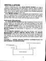
INSTALLATION
Beforeunpackingyour new Alesis MlcRo sERlEs unit,take a
momentto look throughthis instructionmanual.we've made it
brief and informative
and it will answerany questionsthat you
mighthave.some helpfulsetupthoughtsare inctudedalongwith
someapplication
hintsfor eachunit.
EachMlcRo sERlEs unit is designedand engineered
to give
you the highestlevel of professionalperformanceand quatity.
we've madeeach unit musicaland easy to use so that you can
get the most fromyour musicwiththe leastamountof effort.
lnstruments,Microphones
The Alesis MlcRo SERIEShas highimpedance
inputsthatare
ideallysuitedfor use eitherwith instrumentpickupsor line level
signals.Althoughmicrophones
can be connected
direcilyintoany
of the MICROSERIESunits,it is recommended
that they be
connectedto a mixingconsolefirst and then connectedto the
MfCROSERIESas describedin Figures2 or 3 for quietest
operation.
Of the MICROSERIESunits that are stereo,such as the
MICROVERBll, MICROLIMITER,MTCROGATE,and MTCRO
ENHANCER,
eitherleftor rightinputsmaybe used,butsignalwill
only appearon the same side output(example:left input-left
output)sincebothlettand rightchannelsare totallyisolated.See
tigure 1
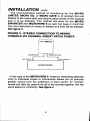
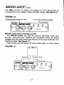
F I G U R E1 - M O N O M I C R O S E R I E S C O N N E C T I O NT O
INSTRUMENT
OR MICROPHONE
TOAMPLIFIER
OR MIXINGCONSOLE
INSTRUMENTOR
LEFTOUTPUT
INSTALLATION cont'd
This is NOTtrue of the MICROVERBll, however'lf the left input
ll is used,the inputsignalwillappearas
onlyof the MICROVERB
at the dry sideof the mixcontrol'
(present
in
channels)
both
mono
MixingConsotes
All of the MICROSERIESunits can handlemono or stereo
sends at all systemlevels.The input circuitryof the MICRO
SERIEScan easilyhandle+4dBvlevels(+20dBvpeaks),while
withthe extremely
havingenoughinputor outputgainto interface
recording
systems.
low signallevelsof budget
The MICROSERIESunits may be connectedto the mixing
consolein severalways.
ll, the
In the caseof the MICROENHANCERor MICROVERB
unit can be used to effectseveralinstrumentsat once by using
the auxiliarysend and returncontrolsof the console.Simply
connectan aux sendof the mixingconsoleto eitherof the inputs
ll (or 2 aux sends
of the MICROENHANCERor MICROVERB
co nnect e dt o b o t h th e l e ft a n d ri g h t i n p uts of the M ICRO
ENHANCERor MICROVERBll for stereooperation)and then
ll
or MICROVERB
connectthe outputof the MlcRo ENHANCER
in
back to eitherthe aux returnsor inputchannels.Remember,
this situation,the mix controlshouldalwaysbe set fully to the
for maximumeffect.Seefigure 2
right(clockwise)
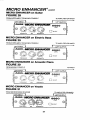
FIGURE2. STEREOCONNECTIONTO MIXING
CONSOLEVIA AUX SENDS
rry1622m
AUXSEND2 LEFTINPUT
RIGHTINPUT
M I C R OS E R I E S
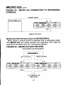
INSTALLATION contd
The recommended
methodof interfacing
for the MIGRO
LlMlrER,MlcRo EQ,or MlcRo GATEis to connectthe unit
directlyto the insertsendandreceivepatchpointsof thechannel
that is to be effected.This methodwill work for the MlcRo
ENHANCER
andMICROVERB
ll as well,but keepin mindthat
onlyoneinstrument
(in monoor stereo)at a timewillbe effected.
Seetigure 3
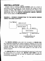
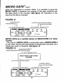
FIGURE3. STEREOCONNECTION
TO MIXING
CONSOLEVIA CHANNELINSERTPATCHPOINTS
as
INSERTSEND
1622u
INSERTRETURN
LEFTOUTPUT
ln the caseof the MICROVERBll, however,dedicatingseparate
units to individualvoices or instrumentsallowsyou to exercise
greatercontrolover the ambienceof each sound.An "overall"
reverbcan then be usedto tie all of the soundstogetherintothe
samespacefor uniformity.
See figwe 4
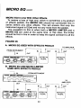
INSTALLATION cont'd
Anotherway to interfaceMICROSERIESunitsto a mixeror
recordingconsolewould be in-lineacrossthe outputof your
mixingconsole. See figure 4 This would be the case if you
neededto effectthe entire mix and would be an especially
appropriate
use for the MICROENHANCER,MICROLIMITER,
and in somecases,the MICROVERB
ll.
FIGURE4 - STEREOCONNECTION
TO THE MICROSERTES
USINGTHE MAINOUTPUTS
a'*.'1622re
MAINOUTLEFT
MICRO
SERIES
LEFTOUTPUT
RIGHTOUTPUT
The MICROSERIESunits(withthe exceptionof MTCROEe)
are especiallydesignedfor stereoprogrammaterialas all of the
unitsare trulystereowithcommonparameter
controlsto prevent
"centershifting",which means
that the balancebrieflyleans
towardsone side due to short term peakson one side of the
stereoprogram.
The MICROEQ canalsobe connected
thisway but 2 unitsmust
be used since it is a mono unit. MIGROCUE AMP(s)can be
connectedin this manneras well to expandyour headphone
monitori
ng capabilities.
6
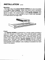
INSTALLATION cont'd
Mounting
All of the unitsin the Alesis MICROSERIESare rack-mountable
in the Micro Rack Adapter, where any three unitsfit perfectly.
Assemblyis quick and simplewith a singlescrewsecuringeach
devicein place.The uniquedesignof the MICROSERIEScase
allowsthe devicesto lock togetherto form a solid rack package,
or to standaloneas singleunits.
Power
The MIGROSERIESis poweredby a remotesupplyproviding9
volts AC througha 3.5mm plug. This externalpowersupply
approachkeepsstray magneticfieldsfrom interferingwith low
levelsignals,allowseasy conversionto alternatepowersources
(220V),and furtherreducesthe unit'sphysicalsize and valuable
panel space.Althoughmany MICROSERIESdevicescould be
poweredby a singlesupply,this is not advisable
as groundloops
couldpossiblyoccurbetweenunits,leadingto excessivehumand
noisein the system,
MICROVERBYI
aE-z .\
zlr-sts ltlGlllllrEEtZ"
.@:@@T@m
POWEN DEFEAT
o
o
\-/(
nuoc
l{
R (X
a
}(
\_/
\-/
\-/
ee25
ALESlscoRpoRATroN
)t
LOS ANGELES, CA
MADErNu s a
-
)(
\
tt
o
\-/
\_/
*#tE1::8yi8.,,j8.,.""6,11i,ilrt6".
PERSoNNEL
SEBVcE
Description
MICROVERBll is a revolutionin the developmentof digital
ratio
reverbin that it representsa phenomenalprice/performance
while reducingthe physicalsize from large,bulky hardwareto
what yo u c a n n o w h o l d i n th e p a l m o f y our hand.The 16
programsin MICROVERB
ll are the resultof yearsof exhaustive
of soundas it occurs
researchby Alesisinto the phenomenon
naturallyin space.Fromsmall,intimateroom settingsto large
spacesto usefulgatedreverbeffects,MICROVERB
unobstructed
powerful
levelof sonicflexibility
that will expandand
ll offersa
polishthe soundof any recording.
Set Computer)
Utilizing
the AlesisR.l.S.C.(ReducedInstruction
p
r
o
v
i
d
e
s
l
l
clean,quiet,
M
I
C
R
O
V
E
R
B
a r c h i t e c t u r et,h e
professional
with the cost and simplicityof
digitalreverberation
springunits.The entiredigitalprocessingsystemis containedon
a singlechip,developedby the AlesisResearchDepartment
s p e c i f i c a l l yf o r t h e M l c R o v E R B l l . U s i n g h i g h s p e e d
( CMOS)silicon
c omp l e m e n t a r y-me ta l -o xi d e -se mi conductor
processing,
the MICROVERBll chip replacesseveralcircuit
whileconsumingvery littlepower.
cardsof components
The reverbprogramswere developedon our interactiveroom
the objective
system.Philosophically,
simulationand development
of reverberationis to enhancea dramaticperformance,adding
MICROVERBYI contd
space,power,and depth.Naturalspacestend to sound more
pleasingthan the simulatedreverbtypes such as springsand
plates,andfor thisreason,we useroomterminology
in desiribing
our programs.The programscover a wide rangeof sizes and
qualities,and includesuch unnaturalconcepti as gated and
reversetypes.
Controls
The Input controlsets the levelof signalthat is appliedto the
MlcRovERB ll and shouldbe set so the overload Indicator
readsin the redonlyon occasionaltransients.
The Mix controldetermines
the amountof wet signal(reverb)or
dqysignalsentto the output. lf the Mix controlis set all the way
to the right,thenonlyreverbwillbe heard.lf the Mix controlis set
all the way to the left,then only dry (uneffected)
signatwill be
heard.The 12 o'clockpositionwill resultin a 50/50mixtureof dry
to reverbedsignal.
The Output controlsets the output level of both channelsof
MICROVERB
ll. Thisshouldbe set so thatthe unitbeingfed by
MICROVERB
ll is notoverloaded.
The Program Select selectsone of MICROVERBll's 16 reverb
programs.
ntCnOYERBllPrograms
SIALLI
AMBIENCE
SXALL2 AMBIENCE
STALL3 SMALLROOM
SIALT'
SMAII PI ATF
ED|UT T SMALL/MEOIUM
ROOM
TEDIUT2 SMALL/MEOIUM
ROOM
TEDIUU3 MEDIUMROOM
TEDIUT' MEDIUMPLATEi
STRONG
IMMEDIATE
ATTACK
TEDIUT5 MEDIUM/LARGE
ROOM
T€OIUX 6 MEDIUMPLATE/SOFTER
DELAYED
ATTACK
LANGE1 LOWDIFFUSION
VOCAIROOM
LARGE2MEDIUM/LARGE
ROOM
LARGE3 LARGEROOM
LANGE4ENDLESSSPACE
GATE.I POWERGATE
GAT€2 BRIGHTGATE
The OverloadIndicator is actuallya 3 coloredLED that shows
severalinputconditions.When the indicatorglowsamber,the
inputsignalto the MICROVERB
ll is too low and the lnput level
shouldbe increased.Whenthe indicatorglowsgreen,the signal
presentlybeingfed to the MICROVERBll is a usablelevel.
When the indicatorglows red, the MICROVERBll is being
MICROVERBYI contd
overloadedand the Input controlshouldbe decreased.
The Bypass Jack, locatedon the rear panel, bypassesthe
reverbsignaland allowsonly the dry signalat the outputs. Any
S PS T ty p e f o o t s wi tch(su ch a s th e re ve r bfootswitchthat
willworkfor thisfunction.
comeswithamplifiers)
sometimes
Operation
ll is easyto usein almostanyapplication.Simply
MICROVERB
do thefollowing:
1. Applya signalto eitherthe leftinputjackfor mono(usedwith
or bothleftand rightjacksfor stereo.
a singleinstrument),
2. Increasethe Input controluntilthe ReCLED brieflylights
"green"
on occasionalprogrampeaks.The LED should remain
most of the time. This indicatesthat there is sufficientlevelto
maintaina goodsignalto noiseratio.
3. Increasethe Output controluntilthere is sufficientoutput
level.
4. Adjustthe Mix controluntilthe desiredratioof dry to wet
s i g n a l i s a c h i e v e d . R E M E M B E R :l n c a s e s w e r e t h e
MTCROVERBlt is used with the aux sends of a recording
console,the Mix controlshouldremainallthe way to the right (ail
wet signal).
5. Selectyourprogramof choice.
A s a g o o d r u l e o f th u mbfo r se l e cti n gp rogr ams,r hythm ic
withostinato(quickly
instruments
suchas drumsand instruments
repeating)type patternsusuallywork bestwith smallerprograms.
Long melodiclines and pads generallysound betterwith larger
rooms.Remember,however,that thisis only a startingpoint. Use
your ears and selecttheprogramthatsoundsbest to you!
ll in your studio
Howto use MICROVERB
The 16 programsin MICROVERBll offer a wide rangeof
ambientspaces.lts compact,atfordableformatmeansthat even
the smallest4 trackstudiocan own morethan one MIGROVERB
ll. One of the greatestdifferencesbetweenhomerecordingsand
10
MICROVERBYI
contd
top flightrecordproductions
is in the qualityand numberof high
performancereverb processors.Simply stated,the big studios
havea lot of digitalreverbsand the smallerstudiosusuallydon't.
MICROVERB
ll changesail that.
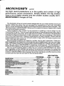
Theillustration
showsa typicalreverbassignment
for a no hotdsbarredrecordproduction.whilethissetupmaynotrepresent
thecapabilities
of yourownrecording
efforts,it doesillustrate
whymodernrecordings
soundsospaciouianddramatic.Th6
16bitprocessor
in MlcRor/ERBII allorvsyoutocreatethissenseof spacewithcrystallineclarityandgreatresolution.
Theseprogramswerechosenfor the purposeof creatinga 'soundstage'for the
performance.
musical
Thereisa welldefinedsenseof threedimensional
spacethatis
occupiedbyeachinstrument:
leftto rightandfrontto back.Theblocksintheillustration
indicatethe physicalplacementof eachinstrument,
and the spreadingof the sound
dueto the psychoacoustic
imagingcharacteristics
of eachprogram.Noticethatthe
smallprogramshavemoreof a centeredspatialimagewhilethelargeprogramsare
wider,moreopenandspacious.
Recornmended
progralrsare listedby numbernelitto each instrument.
Theseprogramsuggestions
arebasedoncurrentpopularusesof digitalrwerb,butuseyor imagF
ption_q1dpleaseexperiment.
Musicalstyle,personaltasteandcreativityare1rcurguid-elines.Thismix usesI MlcRovERBII programssimultaneously.
Theattoroaoifity
ot
MICROVERB
Ileasilybringsatleasta portion
ofthismixwithin
thereachofa//studios.
Themixcontrolsettingsapplyto eitherthemixcontrolon MICRoVERB
II lor stand
aloneoperation,
or thesettingscan applyto thesendsand receivesof a mixingconsole.IMPoRTANT!
whenusedwiththesendsandreceives
of a mixingconsolethbmix
controlon MIORoVERB
II shouldalwaysbe setfullyclockwise,
andthereturnson the
consolepannedhardleftandrightforthefullstereoeffect.
UIXCONTROL
PROGRAT
SNAREDRUM
.
LEAOVOCAL
BACKGROUNDVOCAIS
.....
%Dty
%h
GATEIoT2
. . . . . . . . M E D I U M 4 O R L A R G E6 10
..
MEDIUMs
LEAD INSTRUMENTS (guitiar,sax, svnth, etc.)
LARGE1
RHYTHMGUfTARANDKEYBOARDS... ..
SMALLlor2
HORNSECTION...,,
STRINGS
PERCUSSIONANDCYMBALS.
.ARGE2
LARGE 1
LARGEl OR
..
MEDIUM
2
BASSGUITAR...
SMALL2
H1H4T.............
S M A L Lo Tr 2
11
so-o
50-100
40-50
50-10()
Mtffi
I
I.IIfiNTil
^-
W
-
Rcldrlr dcFr otttp Soundd{p(afurcdon
l-l
o*
I.-,'
I
*tr
dwcudy
nh reUoild d.ill
ot ltvub pogrrn}
Thewithof €dlHod<rcprcen0stplefr btit*sbr€oi.ttEFg.Thefiontbbad(
dimersirn d each blod( representsfre rclalirreserce cf deptt ct€aied by €a.tl
HHT3ffiffiS'#ffi.ffi'ffiffi
mbqwtidrbdePedentmthe
MICROVERBYI
cont,d
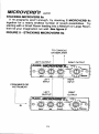
STACKINGMICROVERBils
lf 16 programsaren'tenough,try stacking2 MrcRovERB ils
togetherfor a nearlyendlessnumberof revbrbpossibilities.
Try
startingwitha small Roomfeedingintoa Mediumor LargeRoom,
then let yourimagination
runwild.See ligure 5
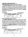
FIGURE5. STACKINGMICRoVERBIIs
TO CONSOLE
ORAMPLIFIER
t
l
I
rcrr oureur |
|
RIGHTOUTPUT
*#ffih-a
"@:.@:-.@i*'6j@
/
\
/
FROM MIXER OR
INSTRUMENT
N
13
\
/
\
S-_, I
MICROLIMITER'
R OulPUI
POWEN
r-\
\-/
svrc
{
\
)
,/
\
L
{
,/
)
"f&1R'"?tPS:^"'l"r
4#F
*"?r+HilFAmUi'A:tr
BACK
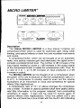
Description
T h e Al e s i s M I CR OL IMIT E Ri s a tru e ster eoin/ster eoout
whichis usedfor automaticgain riding,peak
compressor/limiter
limiting,and specialeffectson bothliveand recordedinstruments
andvocals.
A compressor/limiter,
whichcan be thoughtof as an automatic
fader,veryquicklyreducesgainand attenuates
the signalonceit
level.The numberof dB increaseof the
exceedsa predetermined
inputsignalneededto causea 1 dB increasein the outputsignal
is calledthe compression
rafio.Thus,for
of the compressor/limiter
a ratioof 4 to 1, an 8 dB increaseof inputproducesa 2 dB
increasein output.
when
The MICROLIMITERcan be thoughtof as a compressor
ratio(2:1
the greenLEDs are lit becauseof the low compression
is usuallyusedto even out the volume
to 8:1).A compressor
for special
fluctuations
instrument
of an
or vocaland sometimes
effects(SeeApplications).
ratioof 10:1or abovechangesthe compressor
A compression
intoa limiter.A limiteris usedto preventshorttermpeaks(which
add littleinformation
to the programmaterial)from overloading
amplifiersor tapes. lt also can be used for certaintypesof
specialeffects(See Applications).
Once the yellowLEDs are
fired,the unitbecomesa truelimiterwiththefourthLEDindicating
14
MICRO LIMITER@contd
a compression
ratioof about16:1.sincewe at Alesisfeelthatthe
MICRO LIMITERis more easily and quicktyset up by just
listening,we have eliminatedthesedesignations
from the front
panelof the unit.
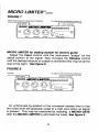
The MICROLIMITERemploysthe "soft-knee"approach,which
meansthat there is alwayssome compressionappliedto all
signals,regardlessof level,but the compressionratiois very low
for low level signalsand automatically
increasesas the signal
fevelincreases.See figure 6
FIGURE6
5
F
l
o
I N P U TL E V E L
The MICROLIMITERalso employsprogramdependentattack
timewhichallowsthe unitto be moremusicalsoundingthanother
compr e s s o r / l i m iteorsn th e ma rke t.B e causeof the unique
charact e r i s t i cosf i ts d e te cti o nci rcu i try which
,
have been
especiallytailoredfor use with a rhythmsection,the unit can be
thoughtof as a "powerbox",addingpunchto bass and drums
with very few of the undesirable
side effectsnormallyassociated
withcompressor/limiters.
Unlikemany other compressor/limiters
on the marketwhich
requireextensivetechnicalknowledgefor operation,the MICRO
LIMITERwas designedspecifically
withthe musicianin mindso it
is bothquickand easyto use and requireslittletrainingto achieve
the desiredresults.
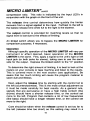
Controls
The input controlsets not only the level enteringthe MICRO
LllllTER, but alsodeterminesthe the amountof limitingwhichwill
be applied.Therefore,the more inputto the unit, the higherthe
15
MICRO LIMITER@cont'd
compressionratio. This ratio is indicatedby the input LED'sin
withthe graphon the frontof the unit.
conjunction
The releasetime controldetermineshow quicklythe limiter
recoversfrom a signalappliedto the input. Farthestto the left is
the fastestreleasetimewhilefull to the rightis the slowest.
The output controlis providedfor matchinglevelsso that no
signallevelis lostdue to the effectsof limiting.
An in/out switchallowsyou to bypassthe MIGROLIMITERfor
comparisonpurposes,if necessary.
Operation
Althoughspecificoperationof the MICROLIMITERwill vary per
instrumentor effect desired,basic operationof the MICRO
LIMITERis the same. First,applya signalto the unit'srightor left
inputjack (or bothjacksfor stereo),takingcare to use the same
sidefor the output. Depressthe in/out switchto the "in" position.
To determine
the rightamountof limiting,it is bestto lookat the
meterson your consoleor tape machineand listento the results.
This is coveredmore in the next section(see application).
Be
awarethat too much limitingwill causethe programmaterialto
seemdullandlifeless.
Next,adjustthe releasetime by startingwith the controlfull to
This is the mostcriticaladjustmentso
the left (counterclockwise).
it must be made carefullyfor best results.As a generalrule,
signalsthat are percussiveor have a high treblecontent(like
drums)shouldhave a shorterreleasetime, or the controlset
more to the left. Programthat containsa lot of low frequencies
(likebass)shouldhavea longerreleasetime,or the controlset
moreto the right.
Careshouldbe takenwhenthe releasecontrolis set too far to
the left (releasetime too short) as this setting may result in a
MICRO LIMITER@contd
slightamountof harmonicdistortion.Also,a phenomenacalled
"pumping"or "breathing"
mightoccur.This meansthat if a rapid
successionof peakswerefed intothe limiter(a staccatoguitaror
synthpart,for instance),the limiterwouldrespondto eachpeakof
the signal,causinga rapidrisein background
noiseas the gainis
increasedafter each peak. Both of these conditionsare a byproductof the limitingprocessand can occurwith any limiter.
However,theseconditionsmay neveroccurduringyour particular
use as they are dependent
on the typeof instrument
fed intothe
MICROLIMITER,and the styleof musicplayed,as well as the
settingof the release control.Simply turn the release control a
bit to the right and either the slight distortionor "pumping"and
"breathing"willgo away!
lf the releasecontrolis set too far to the right(releasetime too
long),the programmay sounddull and lifelessas a resultof
squasheddynamics. Whenin doubtas to how to setthe release
control, it'sbetter to keep it on a shortersetting(towardsthe left)
since fhe MICROLIMITERis most forgivingin operationat this
point and you will mostlikelyget the desiredresults.
Finally,set the output controlby switchingthe in/out controlin,
then out, and adjustthe output controluntilthe levelis the same
regardlessof the positionof the switch.
Application
The MICROLIMITERcan be made to performseveraldifferent
functions,
depending
uponcontrolsettings.
Theseare:
1. Even out the volume differencesbetweenregisterson
instruments.
An exampleof this wouldbe that some bass guitar
stringsare louderthanotherson someinstruments.
The useof a
MICROLIMITERproducesa smootherbassline by matchingthe
volumesof the differentnotes.
2 . M i n i m i z et h e c h a n g e si n v o l u m ew h e n a v o c a l i s to r
instrumentalist
momentarily
changeshis distancefromthe mike.
17
MICRO LIMITER@cont'd
3. Allow an instrumentto be recordedhotteronto tape by
preventingtransients(highlevelpeaks)frompinningthe meter.
"sit" better in the mix by
4. Make a vocal or instrument
decreasingthe signalpeaks and increasingthe lower volume
parts.This actuallyenablesthe signalto be made significantly
the overallsignallevelmeter
louderin the mix whileincreasing
onlyslightly
suchas bassor
5. lncreasethe "punch"of certaininstruments
drums,by allowingthe peak portionof the signalthroughwhile
limitingthe rest.
suchas electricguitar
6. lncreasethe sustainof an instrument
range.
its
dynamic
compressing
by
by controlling
7. Stopdistortiondue to temporaryoverloading
transients.
In the examplesbelow,we can bypassthe normaltechnical
explanationsby simply watchingthe meters and listening. This
will get you the best resultsfrom your MICROLIMITERwith the
leastamountof hassle.
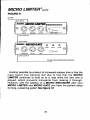
MICROLIMITERfor addingpunchto an instrument
Adjustthe input controluntil the instrument(or instruments)
beginsto brightenon the attackportionof the signal. This should
be at aboutthe first red LED. Be carefulnot to limitthe signaltoo
much as it will start to becomevery dull and lifeless. Also, be
carefulas to the settingof the Releasecontrol(Remember:more
bass = longersetting).The MICROLIMITER,unlikeany other
limiteron the market,is optimizedfor rhythmsectionwork (bass
and drums) allowingyou to add the maximumpunch while
sideeffectsto a minimum.See figure 7
keepingundesirable
18
MICRO LIMITER@cont,d
FIGURE7
F R O MI N S T R U M E NOTR M I X I N GC O N S O L E
T O A M P L I F I EO
RR M I X I N GC O N S O L E
L E F TI N P U T t
MICROLIMITERfor addingsustainfor electricguitar
Adjustthe Input controluntil the instrument',snaps"on the
attackportionof the signal.Now increasethe Releasecontrol
untilthedesiredamountof sustainis achieved(thismaybe all the
way to the right). Seefigure I
FIGURE8
GUITAR
T OA M P L I F I E O
R R M I X I N GC O N S O L E
LEFrf'rpur
]
An unfortunate
by-product
of the increasedreleasetime is that
the noiselevelwillgraduallysurgeto a highlevelwhenno signal
is present. This may be overcomeby insertinga MICROGATE
afterthe MfCROLIMITERto eliminatethe noise.Seetigure g
19
MICRO LIMITER@cont'd
FIGURE9
GUITAR
LEFTINPUT
LEFTOUTPUT
TOAMPLIFIEROR MIXINGCONSOLE
Anotherpossibleby-productof increasedreleasetime is thatthe
input s i g n a l m a y b e co med u l l d u e to fa ct that the MICRO
LIMITERcontinuesto hold on to a note while the next one is
pla y e d ,w h i c h p r e ve n tstra n si e n tsfro m makingit thr ough.
However,with the additionof a MICROENHANCERafteryour
MICROLIMITERand MICROGATEyou have the perfectsetup
for long,sustainingguitar!*e figure 10
20
MICRO LIMITER@cont,d
FIGURE1O
GUITAR
LEFTINPUT
TOAMPLIFIEROR MIXINGCONSOLE
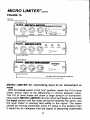
MICROLIMITERfor controlling level of an instrument or
vocal
Withthe in/out switchin the "out"position,watchthe VU or level
meter,and/orlistento the differencesin volumebetweennotes.
The VU or levelmeterwill show a largeamountof movement.
NowswitchIrllCROLIMITERintothe circuitand beginto increase
the Input controluntilthe notesallsound relativelythe same,and
the levelmeteris reactingless wildly to the signal.The meter
shouldbe movingsomewhat,
sinceif it staysin one positionthen
it wouldbe an indicationthat the signalis becomingoverlimited
21
MICRO LIMITER@cont'd
andwilllackdynamics.
Now adjustthe Releaseand Output controlsas in the section
markedoperation.Seetigure 11
As a guide,onlythe firstthreeor four LEDs shouldbe lit during
thisapplication.
F I G U R E1 1
MICROPHONE
OR MIXINGCONSOLE
INSTRUMENT.
,-*r*- 1
TOAMP OR MIXINGCONSOLE
LEFTOUTPUT
Whenset up in this manner,the MICROLIMITERwill act as a
veryeffectivepeaklimiter.This meansthat the MICROLIMITER
c a n b e u s e d t o sto p a n y d i sto rti o nfro m occur r ingin any
subsequenteffectsstages(any devicepluggedin after it) due to
overload.The MIGROLIMITERperformswell in this application
which
becauseof its "softknee"signaldetectioncharacteristics,
meansthat the higherthe signalpeakis, the morelimitingthere
willbe.
22
MICROGATE'
FRONT
POWEN
u
o
v
'vrc
?RGGER
(
R OUTA''
r (
) (
\*_-,/
\_/
\_/
ALE^s.ls_co^BpoFAIoru
--a-.815
LOSANGELES.CA.
ilioe,luse
L
R
) (
NruT
L
.-\
) (
\_/
\,
*#f*Effi.#ffff
*turE*FsNEL
o
iLTx
BACK
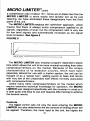
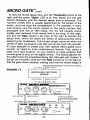
Description
The Alesis MICROGATE is a true stereoin/stereoout noise
gate.As the namesuggests,a noisegate is sort of an electronic
fence gate. When there is enoughpressureon the gate (the
signalis loudenough),the gatewillopento letthe signalthrough.
You can controlhow much level it will take to open the gate (or
how muchpressure),how longthe gate will stay open,and how
fast it will close.Becauseof this amountof control,the MICRO
GATEcan be set to eliminate
any noises,clicks,or buzzeswhich
mightbe a componentof the signalby closingthe gate (turning
off) eitherwhen a signalis not present,or whenthe signaldrops
belowa presetthreshold(or pressure).The MICROGATEwill not
actuallyeliminateall noisethat is a component
of the signal,just
the noisethat existswhenthe signalis not present.This is true of
anygatingdevice.
It can alsobe usedfor a varietyof specialetfectssuchas gating
the reverbon a snaredrumto achievethe popular80'sstyledrum
sound effect,or tighteningup the sound of a live drum kit by
suppressing
leakagebetweendrummics.
23
MICRO GATEtcont'd
Controls
The Thresholdcontrolsetsthe pointat whichthe MICROGATE
will open(letthe signalthrough).Turningthis controlclockwise(to
the right)lowersthe thresholdpoint,makingthe gate easierto
trigger.
The Rate controldetermineshow fast the MICROGATE will
close,with the fastestpositionbeing all the way to the right
(clockwise).
Thiscan alsobe thoughtof as a releasetimecontrol.
A Delay controlallowsthe user to determinehow long the
MICROGATEwill wait beforeclosingaftera signalhas dropped
belowthe threshold.
A series of coloredLEDs are also includedto indicatethe
current status of the MICRO GATE. A red "Close" LED
indicatesthat the gate is closedand no signalis beingallowed
through. A green "Open" LEDindicates
the the gateis open,
havingrisen above the thresholdpoint,and signal is flowing
freely throughthe unit.The yellow"Delay"LEDindicates
thatthe
signal has dropped below thresholdand the MICROGATEis
waiting for a period of time (determined
by the delaycontrol)
beforeclosing.
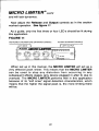
An ExternalTriggerinputcan alsobe foundon the rearpanel.
This inputis sometimescalleda "key"input.The functionof the
ExternalTrigger input is to allowthe MICROGATEto open by
beingtriggeredfroma sourceotherthanthe one pluggedintothe
inputs.An exampleof this is whenan instrument
track(suchas a
keyboard),whichhas beenplayedwith impreciserhythm,can be
tightenedup and the track savedby triggering(or "keying")from
whichwas playedwith moreprecisetime. ln
anotherinstrument
this case,the outputof the snaredrumtrackis pluggedintothe
Trigger Input of the MICROGATEwhichthen has the keyboard
track pluggedinto its normalinputs.Everytime the snare drum
hits, the gate will open allowingthe sound of the keyboard
throughin perfectsync. The lengthof time that the keyboard
stayson will be determinedby adjustingboththe Rateand Delay
24
MICRO GATEtcont'd
controfs. Seefigure 12
FIGURE12
KEYBOARD
TRACK
SNARETRACK
nrxeur
I rnrooe
An In/Out switchis providedto bypassthe MICROGATE if
purposes.
desired,or for comparison
Operation
After connectingyour MICROGATE (referto the sectionon
installation),
makesure that the unit is readyfor operationby
makingsurethatthe in/outswitchis depressed.Thisis important
sincethe status LED'swill flash even if the gate functionis
bypassed.
Whileapplyinga signalto the MICROGATE,turnthe Threshold
controlslowlyto the rightuntilthe green"Open"LEDflashes.Now
slowlyturn the Rate controlto the rightuntilthe gate turnsoff at
the exactmomentthatthe signalstops.Thisadjustment
is critical
sincethe signalwillsound"chopped"
if settoo far to the right,and
not enoughnoisewill be eliminated
if set too far to the left. As a
final step,turn the Delaycontrolslowlyto the right(startingfrom
full counterclockwise)
untilthe smoothesttransitionfrom opento
closedgateis achieved.
As a generalrule,percussive
(likedrums)
typesof instruments
will requireshorterrates,while sustainingtypes of instruments
(likeguitarsor pianos)will requirelongerrates.The Delaycontrol
is most usefulfor thesesustainingtypes of programsas it will
25
MICRO GATE@"ont'a
"chopped"
allowyou to maintainthe signallengthwithoutthe
effectwhilekeepingthe noisefloorto an absoluteminimum'
"chatter",
whichmeansthat
Be carefulalsothatthe gatedoesn't
noise,
clicks,and pops
gate
spurious
is beingtriggeredby
the
just
a bit too low.A cure for
causedby the Threshold beingset
this is to connecta MICROLIMITERbeforethe gate in orderto
true
set the signalto a strong,constantlevel.This is especially
picked
(toms
whengatingdrums,whenleakagefromotherdrums
willoftencausethe gateto
up by the kickdrummic,for instance)
openprematurely.
Application
The MICROGATEis usefulin manyeverydayrecordingand
performing
Beloware just a few of the mostcommon
situations.
waysto putthisdeviceto use.
Pleaserememberthat the controlsettingswill vary depending
used,the styleof musicbeingplayed,
uponthe actualequipment
The settingsare
playingstyleof the musician.
and the particular
nominallycorrecthowever,and shouldserve as a reasonably
goodstartingpoint.
MICROGATE with individualinstrumentsor microphones
(or "noise
The MICROGATEcan be usedas a noisesuppressor
gate")with eitherguitars,basses,keyboards,or microphones
the MIGRO
whenrecording
or playinglive.Whenset up correctly,
GATEwill turn off at the end of each signalenvelopethereby
keepingannoyinghumsandbuzzesout of thesystem.
directlyintoeither
or otherinstrument
Plugthe guitar,keyboard,
plug the same
Now
GATE.
MICRO
right
input
of
the
left
or
the
you
must
usethe right
sideoutput(if you usedthe rightinputthen
output)directlyintoeithera mixingconsoleor amplifier.
takingcare to set
Proceedas in the abovesection(Operation),
26
MICRO GATE@,onra
the Ratecontrolto wherethe signalof the instrument
or
microphone
is not"clipped"
whenthegatecloses.Seetigurel3
FIGURE13
FROMINSTRUMENT
ORMICROPHONE
TOAMPLIFIER
OR MIXINGCONSOLE
LEFTINPUT
LEFTOUTPUT
MICROGATEwith a mixing console
The MICROGATE can also be used to eliminatenoiseand
buzzes,and generally"tighten-up"recordedtracks by being
pluggedintothe insertsendand returnsof the inputchannelsof a
mixingconsole.Se tigure 14
lf the mixingconsoledoes not have insertjacks,or if the insert
FIGURE14
ats16122n
INSERT
SENO
INSERT
RETURN
LEFTINPUT
LEFTOUTPUT
27
I
MICRO GATE'cont'd
jacks are dedicatedto anothereffect,it is possibleto plug the
MICROGATE in betweenthe outputsof the tape machineand
the tape inputsof the console.See figure 15 Operationis the
sameas the aboveexample.
FIGURE15
FROMTAPEDECK
LEFTINPUI
TOTAPEINPUTSOF MIXINGCONSOLE
R I G H TI N P U T
LEFTOUTPUT
RIGHTOUTPUT
MICROGATEas a variable decay for MICROVERBll or other
reverbs
with a MICROVERBll
The useof a MICROGATEin conjunction
will openup a
or any otherreverbwithfixeddecaycharacteristics
See ltgure 16
wholenewrealmof flexibility.
F I G U R E1 6
MIXINGCONSOLE
FROM
LEFTINPUT
RIGHTINPUT
MICROVERB
IIOROTHER
REVERB
LEFTOUTPUT
LEFTINPUT
RIGHTOUTPUT
RIGHTINPUT
LEFTOUTPUT
MICRO GATE*contd
To varythe reverbdecaytime,turn the Thresholdcontrolto the
rightuntilthe green"Open"LED is lit, then slowlyturn the rate
controlclockwiseuntilthe desireddecaytime is achieved.The
"correct"reverbtime is
usuallydeterminedby the tempoof the
music,and how busythe arrangement
is. For example,if many
instrumentsuse the same reverb or the parts containfast
passageswith lots of 16th notes,the mix will usuallysound
muddyand confusedif the reverbtime is too long.ln this case,
just turn the Rate controla bit more to the right to shortenthe
decaytime,whichwill leavethe senseof spaciousness
while
lessening
the muddiness.
The correctlengthwouldbe whenthe
reverbof eachsuccessive
notediesjust as the nextnotesounds.
It's also possibleto createyour own specialeffectgateddrum
sounds,as heardon mostcontemporary
records.First,selecta
largeroomtype program(or any mediumor largeprogramthat
soundsgoodto you) on the digitalreverb. The bestprogramsfor
this effecthavethe smoothestdecaytails(thegatewill "chatter',if
the tail isn'tsmooth).Nowturnthe RatecontrolJar
to the rightso
thatthe gateclosesabruptly,makingsurethatthe reverblengthis
FROMMIXINGCONSOLE
L E F TI N P U TT I R I G H TI N P U T
FIGURE17
LEFTOUTPUT
LEFTINPUT
LEFTOUTPUT
LEFTINPUT
RIGHTOUTPUT
RIGHTINPUT
RIGHTOUTPUT
RIGHT
INPUT
TO MIXINGCONSOLE
LEFTOUTPUT
RIGHTOUTPUT
MICRO GATE'cont'd
notso longas to spilloverontothe nextdrumbeat.Varythe delay
controlfor a smootherreleaseif necessary.For an even more
strikingeffect,inserta MICROLIMITERbetweenthe reverband
the MICROGATE. Seefigure 17
The limitershouldbe set for maximum"punch"settingswith a
highdegreeof limiting(at leastthe firstred LEDshouldlight).Set
the releasetime startingat about halfway.The objecthere is to
set the releasetime (ratecontrol)as long as necessaryto keep
the reverb"tail"smooth.
MICROGATEusingthe triggerfunctionfor gatedreverb
Anotherway to achievea gatedinstrument
sound(likea snare
drum)witha minimumof gatechatteris to feedthetriggerinputof
whilegatingthe
the gate with the dry signalof the instrument
reverbin the abovefashion.Thisassuresthe ultimatein chatterfree operationas the rate is now controlled by the envelopeof
the instrumentitself. Seefigure 18
FIGURE18
FROMAUXSENDSOF CONSOLE
LEFTINPUT
LEFTOUTPUT
R I G H TI N P U T
R I G H TO U T P U T
TOMIXINGCONSOLE
LEFTINPUT
LEFTOUTPUT
R I G H TI N P U T
INPUT
TRIGGER
DBYSIGNALFROMINSTRUMENT
(EXAMPLE:
SNAREDRUM)
30
R I G H TO U T P U T
MICRO GATEtcontd
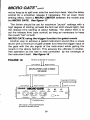
MICROGATEusing the trigger function for specialeffects
Althoughthe MICROGATEtriggerfunctionis usuallyusedfor
syncingetfectsbetweentwo instrumentssee figure 19, it can
a ls o b e u s e d f o r se ve ra l i n te re sti n gspecial effects and
enhancements.
The mostcommonof theseis thetuningandfatteningof a drum
(a kickdrum,for instance)
by addinga lowoscillator
toneof about
60hz(i.e.froma synthesizer)
to the drumwhichis thensyncedby
the MICROGATE. A signalfrom the drum is then appliedto
the Trigger inputcausingthe gate to openwhenthedrumhits.
The outputof the MICROGATEshouldthenbe mixedback into
the drum soundat the mixingconsole.By tuningthe oscillator
between40 and 80 Hz, you will be ableto add botha fullness
to thedrumas wellas tunethe drumto a specificpitch.
F I G UR E1 9
TOMIXINGCONSOLE
OSCILLATOR
OR SYNTHESIZER
L E F TI N P U T
DRUMTRACK
LEFTOUTPUT
TRIGGER
INPUT
A variationto the abovewould be to injectwhite noisefrom a
synthesizerinsteadof an oscillatortone. This would add more
snapor "snares"to a snaredrum.*e figure 19
31
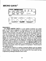
MICRO EQ
FRONT
FOW€F
O
tu^c
AtE:sls^991?gl|loN1Qt ee15
LVO AIIgELEJ,
UA.
MAOE IN U S A
oo.
*#EE$gV'€i,€!b"63n,H,"d*
SEfuICE 4FSqNEL
BACK
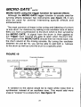
Description
The Alesis MICROEQ is a mono 3 band semi-parametric
equalizerwith sweepablefrequenciesand switchablebandwidth
controls.
Equalization,
or EQ, is the abilityto controlthe harmonic
bala n c e ,o r t i m bre ,o f a n i n stru me n t,and can be used to
compen$atefor frequencydeficienciesin either microphonesor
Therearethreedifferent
soundequipment.
all
typesof equalizers,
familiarwith.
of whichyouare probably
The mostcommontypeof equalizeris the Shelvingtype.This is
the simplebass and/ortreblecontrolnormallyfoundon stereo
systems,guitaramplifiers,etc. The term shelvingrefersto the
plateau,or shelf,beginning
amplitude
at the turnoverpoint(s)(100
Hz and 10kHzin the diagram)and extending
to the high(or low)
The frequencies
end limitof the equalizer.
below(or above)the
turnoverpointof the shelfare also atfected,but less and lessso
the furtherawayfromtheturnoverpoint.
Turnover
Frequencles
MICRO EQ cont'd
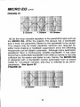
The secondtype of equalizeris the GraphicEqualizerwhich
mostpeoplehaveseenon soundsystems,somehomestereos,
and manyguitartype amplifiers.
This devicegets its namefrom
the fact that the controlsettingsactuallyform a graph of the
frequencyspectrum.Whileshelvingequalizers
work on broad
graphic
sectionsof the frequencybandwidth,a
equalizeris
slight l ym o r es o p h i sti ca teth
d a n th e S h e l vingequalizeras it
dividesthe frequencyspectruminto sectionscalledbands.See
figure 20
FIGURE20
Bands
The rangeof frequencies
boostedor cut in eachbandis referred
to as the bandwidth.This bandwidthis normallymeasuredin
musicaloctaves,so on a simplegraphicequalizer
containing
only
5 bands,each band would have a 2 octavebandwidth,and a
graphicequalizer
moresophisticated
with31 bandswouldhavea
1/3octavebandwidth.
Generallyspeaking,a 1l3rdoctaveequalizeris normallyused
for room tuningand feedbackcontrolwhile a 1 or 2 octave
equalizeris usedfor normaltonalshaping.See figure 21
33
MICRO EQ cont'd
FIGURE21
2 Octave
1 Octave
1/3 Octave
By far the mostversatileequalizeris the parametrictypesuchas
the MlcRo EQ. Whilethe graphicEQ alwayshas a bandwidth
that is fixed,the parametricallowsfor the bandwidthto be varied.
This meansthat far fewerequalizersectionsare requiredfor
sincethe offending
eithertonalshapingor feedbacksuppression
precisely.
manyparametric
Although
in
be
dialed
can
frequencies
variablebandwidth,it has been
equalizershave a continuously
foundthat a switchablebandwidthfromwideto narrowis not only
but far easierand fasterto use.Hence,the MICROEQ
sutficient
is designedwith a bandwidthcontrolswitchablelrom 2 octave
(wide)to llzoctave (narrow),and thus is referredto as semi'
parametric. Seeligure 22
FIGURE22
2 Octave
1/2Octave
34
MICRO EQ cont'd
Controls
Mid Freq Level
Frgq Select
Input Level
Freq Width
Low Freq Width
High Freq Width
The lnput controlsets the levelof signalthat is appliedto the
MICROEQ. Sinceaddinglarge amountsof equalization
can
sometimeslead to overloadof the units connectedafter the
MICROEQ, the Input controlwill serveto maintaina distortion
freesignalby controlling
the overallinputlevel.
An In/Out switchallowsthe user to bypassthe MICROEe for
comparisonpurposes.
The Lo Freq Select (the outer ring of the dual concentricknob)
alfowsyouto selectanyfrequencybetweenZ0 Hz and 1kHz.
The Lo Freq Level (the inner ring of the dual concentricknob)
allowsyou to eitherboostor attenuateany frequencyselectedby
the Lo Freq Selectknobup to a maximumof +15d8.
The Lo Freq Width controlsthe bandwidthcurve to selectthe
one best suitedfor your application.With the switchin the "out"
MICRO EQ cont'd
position,the bandwidthis 2 octavewhile with the switchin the
position,
is ll2octave.
the bandwidth
depressed
The Mid Freq Select (the outerring of the dual concentricknob)
allowsyou to selectanyfrequencybetween250 Hz and 6kHz.
knob)
The Mid Freq Level (the innerringof the dual concentric
by
frequency
selected
you
any
to eitherboostor attenuate
allows
+15d8.
the Mid FreqSelectknobup to a maximumof
to the Lo Freq Width
The Mid Freq Width operatesidentically
switch.
The Hi Freq Select (the outerring of the dual concentricknob)
between1.5kand20kHz.
allowsyouto selectanyfrequency
The Hi Freq Level (the innerring of the dual concentricknob)
allowsyou to eitherboostor attenuateany frequencyselectedby
the Hi FreqSelectknobup to a maximumof t15dB.
The Hi Freq Width operatesidenticallyto the Lo Freq Width
switch.
The Clip LED lightswhenthe MICROEQ is beingfed too hot a
Whenthisoccurs,turndownthe
overloaded.
signal,andtherefore
Inputcontroluntilthe Clip LEDno longerfires.
Operation
The bestwayto useyourMICROEQ is as follows:
1. Start by turningthe Level controlof the desiredfrequency
band(low,mid,or high)tomaximum.
with the FrequencySelect knob until
2. Sweepthe frequencies
you find the frequencythat you wish to cut. (lf the Clip LED
shouldlight,turndownthe Inputcontrol).
3. Now,backoff the Levelcontroluntilthenewamplituderesults
in a pleasingsound.
MICRO EQ cont'd
4. Depressthe Width switch(lo, mid,or high)to see if the result
is moresatisfying
in the l12octave(in)positionor2 octave(out).
lf youshouldfindthatyou are addinglargeamountsof Ee in all
3 bands,thenthe overalleffectis the sameas simplyraisingthe
volumelevel. In thiscase,do thefollowing:
1. Startby turningthe Levelcontrolof thedesiredfrequency
band(lo,mid,or high)tomaximum.
2. Sweepthe frequencies
withthe FrequencySelectknobuntil
you find the frequencythat you wish to cut. (lf the Clip LED
shouldlight,turndownthe lnput control)
3. Now,backoff the Level controluntilyou are cuttingthe level
insteadof boosting.
4. Depressthe Widthswitch(lo,mid,or high)to see if the result
is moresatisfying
in the 1/2octave(in)positionor 2 octave(out).
As with any signalprocessor,the MICROEe shouldbe used
with discretionsince too much EQ, indiscriminately
used, can
makethe soundworseinsteadof better.Althoughit is a wonderful
deviceand will helpyoursounda lot,rememberthat a littlegoes
a longway.
Belowis a chartthatwill helpyouzeroin on the keyfrequencies
of somepopularinstruments.
Remember:The chart seruesonly as a startingpoint. Ultimately,
you must useyour earsas a guide.
Bass Guitar
Attack or pluck is increasedat
700 or 1kHz, bottom added
at 60 or 80 Hz, string noise
at 2.5kHz
BassDrum
Slapat 2.5kHz,bottomat 60 or
80 Hz,air at 10kHz
37
MICRO EQ cont'ct
Snare
Fatnessat240Hz,crispnessat
1 to 2.5kHz,bottomat 60 or
80 Hz
Hi hat and CymbalsS h i m m e r a t 7 . 5 t o 1 0 k H z ,
clang or gong sound at
about 200 Hz
A tta ck a t S kHz, fullness at
Toms
Piano
24OHz
Attack at SkHz,fullness at 80
or 12OHz
Body at 24OHz, clarity at
2.SkHz
B o d y a t 240H2, clarity at
2.SkHz, b o ttom at 80 or
120H2
Bass at 80 or 12OHz,presence
Horns
at 2.5 to SkHz,air at 10kHz,
honky-tonk sound at 2.5kHz
as bandwidth is narrowed,
resonanceat 40 to 60hz
F u fl n e ss a t 120 or 240 Hz,
Floor toms
ElectricGuitar
AcousticGuitar
Voice
Harmonica
shrill at 7.5 or SkHz
Fuflnessat 12OHz,boominess
at 200 to 24OHz, presence at
SkHz,sibilanceat 7.5kHz,air
at12 to 15kHz
Fat at 24OHz
38
MICRO EQ cont'd
Conga
Resonantring at 200 to 240lHz,
presenceand slap at 5kHz
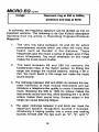
In summary,the frequencyspectrumcan be dividedup into six
importantsections.The followingis de Gar Kulka'sdescription
re p rin t e df r o m h i s a rti cl ei n R e co rd i n gEngineer /pr oducer
Magazine:
1 . T h e v e r y l ow b a ss b e tw e e n 1 6 and 60 Hz which
encompassessoundswhich are often felt more than
h e a r d , s u c h a s t h u n d e r i n t h e d i s t a n c e .T h e s e
frequenciesgivethe musica senseof powereven if they
occur infrequently.
Too much emphasison this range
makesthe musicsoundmuddy.
2. T h e b a s s be tw e e n 6 0 a n d 2 S O Hz contains the
fundamentalnotes of the rhythmsection,so Eeing this
rangecan changethe musicalbalance,makingit fat or
thin.Too much boost in this rangecan make the music
soundboomy.
3. The midrangebetween250 and 2000 Hz containsthe loworder harmonicsof most musicalinstrumentsand can
introducea telephone-like
qualityto musicif boostedtoo
much. Boostingthe 500 to 1000 Hz octave makesthe
instruments
soundhorn-like,whileboostingthe 1 to 2kHz
octave makes them sound tinny. Excessoutput in this
rangecan causelisteningfatigue.
4. The uppermidrangebetween2 and 4kHz can mask the
i m p o r t a n tsp e e ch re co g n i ti o nso unds if boosted,
introducinga lispingqualityinto a voice and making
soundsformedwith the lips such as "m", "b", and "v"
39
MICRO EQ ant'd
indistinguishable
T .o o m u c h b o o s t i n t h i s r a n g e ,
especiallyat 3kHz, can also cause listeningfatigue.
Dippingthe 3kHzrangeon instrumental
backgrounds
and
peaking
slightly
3kHz on vocalscan make the vocals
audiblewithouthavingto decreasethe instrumental
level
in mixeswherethevoicewouldotherwise
seemburied.
5 . The presencerangebetween4 and 6kHzis responsible
for
the clarityand definitionof voices and instruments.
Boostingthis rangecan makethe musicseem closerto
the listener.Adding6dB of boost at SkHzmakesa mix
soundas if the overalllevelhas been increasedby 3 db.
As a result of this effect, many recordcompaniesand
masteringengineersmakea practice of addinga few db
of boost at SkHzto make their productsound louder.
Reducingthe SkHzcontentof a mix makesthe sound
moredistantandtransparent.
6 . The 6 to 16kHzrangecontrolsthe brillianceand clarityot
sounds.Too muchemphasisin this range,however,can
producesibilanceon vocals.
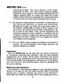
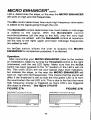
Application
Sincethe MICROEQ can be usedwith any electricinstrument
or microphonerequiringtonal alteration,here are some generic
s u g g e s t i o n as s to se tu p .S i n ce e a ch i nstr umentwill sound
differentdue to the uniqueness
of the instrumentitself,the typeof
musicbeingplayed,the arrangement,
and the touchof the player,
you must use your ears (and the abovechart)to ultimatelyfind
the correctsettings.
MICROEQ with Rockmanru
The Rockmanruhas becomea stapleof homerecordingstudios
thanksto its ease of use and great sounds.When connected
directlyinto a console,however,the soundof the Rockmanru
doesdifferfromwhatyou normallyhearin the headphones
due to
40
MICRO
EQ cont'd
pr ovide.
the t on a l c o l o r a t i o nth a t th e su p p l i e dh e adphones
Therefore,
ScholzR&Dsuggestthat you makethe followingEQ
whengoingdirect.
adjustments
+3 to +6 at 4kHz
+3 to +6 at 500H2
-4 to -6 at 200H2
The MICROEQ providesthe perfectaccompaniment
for the
RockmanrM,
restoring
the losttonalqualities
thatyou are usedto.
Use2 MICRO EQb tor stereo.
FIGURE23 - MICRO EO WITH ROCKMANTM
FROMGUITAR
ROCKMANTM
AtEts.s
lyHl}GllDriaFRa
+-lsnrsda |lrolu
O
'@;*@rffiH@'hl5
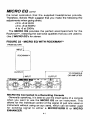
MICROEQ Gonnectedto a RecordingConsole
Generally
speaking,it is bestto usethe insertjacksof a console
when you want to use the MlcRo Ee on an instrument.
This
allowsfor the individual
controlof the signalof just one vocalor
instrument
withoutusingan aux send,whichcan be betterused
f o r s e n d i n gs i g n a lt o e i t h e ra M r c R o v E R B l l o r M l c R o
ENHANCER.
41
MICRO EQ cont'd
TO RECORDING
FIGURE24 - MICROEO CONNECTED
CONSOLE
SEND
INSERT
--l
atersl622
m
N
I
T
RETURN
INSERT
ll
MICROEQ With ReverbsSuch As MIGROVERB
bright.
Manytimesa reverbsoundis requiredthat is artificially
that mightbe
The MICROEQ can easilyprovideany coloration
follows:
your
as
mix.
Connect
requiredto enhance
FIGURE25 . MICRO EQ WITH REVERB
FROMMIXEROR INSTRUMENT
rrh4rrEDeol?
Es
o
|IACqOEA
'@;=-@='W-,@
---lf-
ourl
OR
TOCONSOLE
AMPLIFIER
42
rao-t-.w,rue ll,oou. @
T-l
low
MICRO EQ contd
MICROEQ In-LineWith Other Effects
To restorea loss of high end, whichis sometimesa by-product
of effectspedals,the MlcRo Ee should be connectedfirst in
series beforeany other etfects.This will ensurethat only the
instrument
signalis EQedand not any noisefromthe pedals.
The exceptionto this is when both a MlcRo LlMlrER and a
MlcRo EQ are used at the same time. In this case, the limiter
shouldbe firstin linein orderto keepthe signalconstantto all the
etfects.
FIGURE26
A. MICROEO USEDWITHEFFECTSPEDALS
TOAMPLIFIER
-l^
FROMINSTRUMENT
EFFECT
PEDAL
EFFECTS
PEDAL
B. MICROEQANDMICROLIMITER
USEDWTH EFFECTSPEDALS
t N
FROMINSTRUMENT
TO
AMPLIFIER
PEDAL
EFFECTS
PEDAL
MICROENHANCER'
FRONT
R
a)
r(r ' ' v (
ryrc
) (
\-/
^LSS|S aarooaD.rtu
LoSANGELES,cA.
)
{
t
\_-/
\__/
-
El=!c3
iloeuu
se
L
IiFI't
{
l
\_-/
rcEIS@CffiEW
EFSSmTTOUEO
$rcEffiI
BACK
Description
The Alesis MICROENHANCERis a stereoin/stereoout device
that adds high frequencyinformation(high end) to program
materialin a differentway thana normalhighfrequencyequalizer.
Unlikemost other equalizers,which boost noise as well as the
signal,the MlcRo ENHANCERonly booststreble information
when it alreadyexists in the programmaterial,thus addingthe
hig h e n d s p a r k l ew i th o u tb o o sti n gn o i se.Also, the MICRO
ENHANCERdiffersfrom, and is superiorto, other types of
psychoacoustic
enhancers on the marketsince others use a
distortionprocesswhichis ultimatelyobjectionable.
The MIGROENHANGER
can be thoughtof as a dynamicsemiparametricequalizer,in a boost only mode, as it is capableof
performingmanyof the functionsof a parametric.By varyingthe
balancebetweenthe Threshold,Mix, and Bandwidthcontrols,a
wide varietyof trebleboostetfectsmay be achieved,all without
the additionof any noisenormallyassociatedwith equalizers,or
distortionelementsnormallyassociatedwith psychoacoustic
enhancers.
Controls
The Threshold control,in conjunctionwith the multicolored
44
MICRO ENHANCER@,O't,A
LEDs, determines
the slope,or the way the MICROENHANCER
willworkon highand midfrequencies.
The Mix controldetermines
howmuchhighfrequency
information
is addedto the signalgoingthroughthe unit.
The Bandwidthcontroldetermines
howmuchtrebleor mid-range
is added to the signal. With the Bandwidth control
(all the way to the left),only the very high
counterclockwise
frequenciesare added; with the Bandwidthcontrolat maximum
(all the way to the right)upperand lower midrangefrequencies
are addedas well.
A n I n / O u t s w i t c h a l l o w st h e u s e r t o b y p a s st h e M I C R O
ENHANCER
purposes,
for comparison
if so desired.
Operation
Afterconnectingyour MICROENHANCER(referto the section
on installation),
beginby turningthe Thresholdcontrolto the right
(clockwise)
untilthe red LED lights.Make sure that the In/Out
switchhas beenpressedto the "in" positionor the LEDs will not
fire. This unit'sLEDs are not your typicalinputlevelindicators,
but indicatethe slope,or the way the MICROENHANCERwill
workon highand midfrequencies.
Thismeansthatthe soundwill
differif the thresholdis set so that the first greenLED is lit from
the soundwhenthe red LEDis lit.Thisis dueto thefactthatmore
highfrequencyenergyis triggeredas more LEDs are triggered
(theslopeis altered). Seetigure 27N278
FIGURE27A
FIGURE278
BANDWIDTHControlFullLeft
BANDWIDTH
ControlFullRioht
I
I
)uJ
tr
E
uJ
FREQUENCY
45
MICRO ENHANCER@"o,t'a
Now beginto turn the Mix controlto the right (clockwise)until
the desiredamountof highfrequencyboostis achieved.Youcan
thinkof the Mix controlas an amountcontrol,as this is the one
that will add the amountof high frequencyboostdesiredto the
.
signal(orsignals)thatyousendto the MICROENHANCER
Now turn the Bandwidthcontroluntilthe desiredbalanceof
Startwiththiscontrolall the way
highsand midrangeis achieved.
to the right(clockwise)or at full bandwidth,and adjustit untilthe
instrumentor microphonereachesthe point of greatestclarity.
Be careful to avoid adding excessive midrange which will make
an instrumentOR vocal sound harsh.See the next sectionfor
morespecificapplications.
In orderto comparethe enhancedsoundto the originalsound,
depressthe ln/Out button.
You shouldexperimentwith differentsettingsof the Threshold
controland LED indicatorsas the soundwill vary dramatically
betweenvarioussettingsof the Threshold,Mix, and Bandwidth
controls.Also,don'tbe afraidto drivethe unit hardso as to keep
the red LED on all the time as this is whenthe MICRO
is operating
at its maximum.
ENHANCER
Application
The MICROENHANCERis an extremelyversatiledeviceand
may be used in a varietyof applications.Duringrecordingor
playinglive,theMICROENHANCER
canbe usedas the ultimate,
guitars,
quietest
keyboards,and vocaland
and
trebleboosteron
mics.
instrument
and helpfulhints. Please
Here are just a few possibilities
will
rememberthat the controlsettings vary dependinguponthe
actualequipmentused,the styleof musicbeingplayed,and the
particularplayingstyleof the musician.The settingsare nominally
'correcthowever,and shouldserveas a reasonablygood starting
point.
MICRO ENHANCER@cont'd
MICROENHANCER
on Guitar
FIGURE28
FROMINSTRUMENT
ORMIXING
CONSOLE
TOAMPLIFIEFOR MIXER
MICROENHANCER
on ElectricBass
FIGURE29
FROMII.ISTRUMENT
OR MIXINGCONSOLE
TOAMPLIFIEBOR MIXER
MICROENHANCER
on AcousticPiano
FIGURE30
FROMMIXINGCONSOLE
TO MIXER
MICROENHANCER
on Vocals
FIGURE31
FROMMICROPHONE
OR MIXER
TOAMPLIFIEROR MIXER
47
MICRO ENHANCER',onra
MICROENHANCER
on Guitarthrougha RockmanrM
The MICROENHANCER
restoresthe highendthatis lostwhen
plu g g i n gt h e R o c kma n rM
d i re ctl yi n to a n am plifieror mixing
console.Thisis becausethereis a certainamountof trebleboost
providedby the headphones
suppliedwiththe RockmanrM
that is
missingwhenthe headphones
are not used.Now you can hear
yourguitar/RockmanrM
in all its glorywiththe helpof the MICRO
ENHANCER.See figure 32
FIGURE
32
L E F TI N P U TI I R I G H TI N P U T
ToAMPLTFTER
oRMrxER
LEFTOUTPUT
I I RIGHTOUTPUT
MICROENHANCER
during mixdown
The MICROENHANCER
can be usedto add highend sparkle
and presencewhen mixing.This is particularly
usefulin home
recordingformatswherelimitedbandwidthand distortionin the
processrobsimportanthighfrequencyinformation
recording
that
givespresence,
crispness,
andpunchto homerecording
efforts.
Connectthe leftand rightoutputsof the mixingconsoledirectly
to the inputsof the MICROENHANCER,
thenplugthe outputsof
the MICROENHANCERdirectlyinto the mixdowntape deck.
*e figure 33
FIGURE33
48
MICRO CUE AMP
FRONT
o,eooooo.
R INPUT1 L
o\lss:91?9l{loN
LVO AI\UELE>,
UA
STEREOUNEOUT F I}IPUT2 L
1Qr eq15
MADE IN U S A
*#*13'.8vl3'^f'.'""63f,H36"'
S E A V C TO I F S O \ T I .
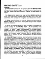
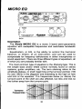
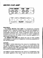
Description
T h e Al e s i s M I GR OC U E A MP i s a h eadphoneamplifier
equippedwith 2 separateheadphonechannelsand designedto
accept up to 2 stereo low level signalsand boost them to a
comfortable
listeninglevel.These2 separatestereoinputsare
c omp l e t ew i t h t h ei r o w n l e ve l co n tro l so n each headphone
channeland give you the abilityto mix 2 sourcestogetherfor a
widerangeof applications.
The MIGROCUE AMP also allowsthe userto chainmultiple
unitstogetherto expandthe headphonemonitoringcapabilities
of
any recordingsetup.
Gontrols
The Input 1 controldeterminesthe amountof amplification
that
the signalappliedto the input 1 jack on the back panelwill
receive.The left-handInput 1 controldeterminesthe levelfor the
Out t headphonejack.The right-handInput 1 controldetermines
jack.
the levelforthe Out 2 headphone
The Input 2 controldeterminesthe amountof amplification
that
the signal appliedto the input 2 jack on the back panel will
49
MICRO CUE AMP cont'd
the levelfor the
receive.The left-handInput 2 controldetermines
jack.
Out t headphone
the levelfor the Out 2
tnput 2 controldetermines
The right-hand
jack.
headphone
output
The MICROCUE AMP features2 separateheadphone
jacks,eachwith independent
levelcontroloverinputs1 and2.
by
outputwiththe volumecontrolled
Out 1 is a stereoheadphone
the leftInput 1 andInput2 controls.
Out 2 is a stereoheadphoneoutputwiththe volumecontrolledby
the rightInput 1 andInput2 controls.
thatthe unitis on.
ThegreenLEDindicates
The Input 1 Jacks on the backpanelare a stereoiackwhichcan
to the stereoauxiliarysendsof a mixing
beusedfor connection
suchas guitaror
inputfor an instrument
an
as
or
used
console,
practicing.
keyboardfor private
The lnput 2 Jackson the backpanelare a stereojackwhichcan
be used for connectionto the stereoauxiliarysendsof a mixing
suchas guitaror
console,or usedas an inputfor an instrument
k e y b o a r df o r p r i va tep ra cti ci n gT. h e In put 2 Jack is also
paralleled
withthe StereoLine Out Jack for chainingadditional
MICROCUEAMPStogether.
Stereo Line Out is usedfor chainingadditionalMICROCUE
to Input2 is
AMP unitstogether. Only the signalapplied
availableat the StereoLine Out.
Operation
yourMICROCUEAMP (referto the sectionon
Afterconnecting
into eitherOut 1 or
simplyinsertyour headphones
installation),
1 and/orInput 2
panel,
Input
the
and
turn
front
2
on
the
Out
MICRO
is
reached.
volume
controluntilthe desiredheadphone
eitherlow
driveanyset of headphones,
CUEAMPwilladequately
(8 ohms)or high(600ohms)impedance.
50
MICRO CUE AMP contd
Please Note: lf you are connecting just one source to your
MrcnO CUE AMP, make sure that the unused input control is
turnedcounterclockwise(to the left, or off). This wiil preventany
unwanted,stray noisesfrombeingheard.
Application
The Alesis MICROCUEAMP is a convenient
and inexpensive
time saver,suitablefor numerousapplications.
This litilebox will
come in handywhereveran extraset of headphonesis need,so
don'tlimityourselfonlyto theseexamples.
MICROCUEAMP Used For Additional HeadphoneOutputs
T h e M I C R O C U E A MP i s p e rfe ctfo r adding additional
headphoneoutputsto a system.Beloware severalmethodsto
accomplishthis. Femember:The MICROCUE AMp hasstereo
input jacks. Therefore, sends I and 2 or main outs must
terminatein a stereoplug.
FIGURE34 - MICROCUEAMP/CONSOLE
INTERFACE
A. USINGTHEAUXSENDS
AUXSEND1
TO OTHERMICRO
CUEAMPS
o
F*O
I
v
neaopHoues
B. USINGTHE MAIN OUTPUTS
MAINOUTLEFT
STEREOLINEOUT
g,@@g
HEADPHONES
51
MICRO CUE AMP cont'd
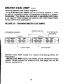
GhainingMICROCUEAMPSTogether
SeveralMICROCUEAMPSmay be connectedtogetherin order
to add an unlimitednumberof headphoneoutputsto a system.
Remember: The Stereo Line Out jack is paralleled with lnput
2, so lnput 2 must always be used as the main input when
being used in this application.
FIGURE35. CHAININGMICROCUE AMPS
-t
STEREOLINEOUT
FROMMIXINGCONSOLE
/
INPUT2
.48
lrccxD
G
/
-7-t
'
\
\
TOOTHER
M|CRO
cUEAMPS
\ . l t-----.---.-----
I|NPUT2
aE
@@9.@e9"
I
,roor*o*r,
HEADPHONES
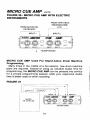
MI CR O C U E AMP U se d F o r Qu i e t P r acticing W ith An
Instrument
MICROCUE AMP makesthe perfectprivaterehearsalmonitor
system.Simplyconnectas shownon the next page,turn up the
volume,andgo for it!
52
MICRO CUE AMP cont'd
FIGURE36. MICROCUEAMPWITHELECTRIC
INSTRUMENTS
FROMTAPEDECK,
DRUMMACHINE,
ETC.
FROMGUITAROR
KEYBOARD
rNPUr
1
At.Cs.s lu!c'?fD
INPUT2
I
AE
M,
t@@.: -ffiffii oq
-p-p-
ourz
HEADPHONES
MI CR OC U E AM P U se d F o r S ta n d -A l oneDr um Machine
Programming
Manytimesin the middleof a hot session,newdrummachine
partsare required.
lnsteadof usingup valuablestudiotimefor
programming,
the MICROCUEAMP can be pressedintoservice
for a privateprogramming
sessionwhileyour expensivestudio
timeis betterusedon otherrecording.
FIGURE37
,a'.gs
ALESIS
HR-16/HR.168
|!c!r!
dE
AE
'@@.9,
-v:w
-A^A-
\ / / a
OUT 2
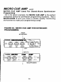
MICRO CUE AMP cont'd
M I C R O C U E A M P U s e d F o r S t a n d - A l o n eS y n t h e s i z e r
Programming
As in the aboveexample,the MICROCUE AMP is the perfect
programming
companion
devicefor synthesizer
situations.Add a
M I C R O V E R Bl l a n d y o u h a v e a s t u d i oq u a l i t ym o n i t o r i n g
environment
to makeyourprogramming
a snap.
FIGURE39. MICROCUEAMPFORKEYBOARD
PROGRAMMING
FROM
KEYBOARD
I
lnr
At.Ets FllrCHDArcltaDEgt
on*-. --..
",@.@-@%o)ru
/
\
/
\
/
\
. 6 _ r l
ot@
HEADPHONES
54
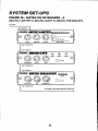
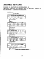
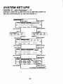
SYSTEMSET-UPS
FIGURE40 - GUITAROR KEYBOARDS.A
(MICROLIMITER
to MICROGATEto MICROENHANCER)
GUITAR
55
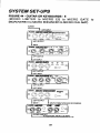
SYSTEMSET.UPS
-B
FIGURE41 . GUITAROR KEYBOARDS
(MICROLIMITER
to MICROEQto MICROGATE)
GUITAR
56
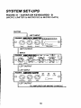
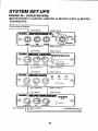
SYSTEMSET-UPS
FIGURE
42. GUITAR
ORKEYBOARDS.
C
(MlcRoLIM|TER
to MTCRO
EQro MTCRO
GATEto MtcRo
ENHANCER)
LEFTINPUT
LEFTOTJTPUT
TO AMPLIFIEROR MIXINGCOT,ISOLE
57
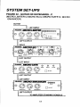
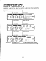
SYSTEMSET-UPS
FIGURE43 . GUITAROR KEYBOARDS.D
( M I C R O L I M I T E Rt o M I C R O E Q t o M I C R O G A T E
MICROVERB
llto MICROENHANCER)
-t
GUTTAR
LEFTNPUT
o .\__/
f ' ) ' - f ' ) -f' ) !l
,---@
\/
\J ,tVa ^*,
INPIT
AELEISE
OU|PUI
r-errotnrur
I
I rrurur
-J.15.1tu8 A=,oi
F!E|C3ID ClAr Frc
Mts
'@;*-@='ffinW;'
Lerrorrnn
I
I urrrurur
o
o
o
. MN
-
usr
aos
a :\g_,y4_.y4
R€;l-CaA:A
'
!,,,o'
lerrourrur
I LEFTNPUT
I
o
urrourrur
IT LEFTI.IPUT
58
l\v
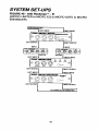
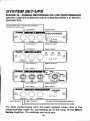
SYSTEMSET.UPS
FIGURE44. GUITAROR KEYBOARDS.
E
( M I C R O L I M I T E Rt o M T C R OE Q t o M T C R OG A T E t o
MICROVERB
ll to MICROENHANCER
to MTCRO
CUEAMp)
GUTlrAR
-1
'
LEFT INRJT
oooooo
I |€Frcurpur
[*r*
LEFrqnpur
J
I LEFTNRJT
I LEFrourpur
I r-errrrunrr
E:{}!G4o€tll.aFB
I
oooo
r-erra,rrnrr
I r.lRJTl
[,"r-r
59
r*rntopE oEcKoRcor{solE
SYSTEMSET-UPS
FIGURE45 - with RockmanrM- A
(MICROLIMITER
to MICROGATEto MICROENHANCER)
ROCKMAN
RIGHTINPUT
,'t€s's I;GBO !.s!!EP
g@..@@@@@O
f1 ,r,our
INPUTIEIEL
LEFTOUTPUT
RIGHTOUTPUT
LEFTINPUT
INPUT
RIGHT
A€S'=;ICFOG4trE
@ O
;,
',i"t
o
'- z6,_zA,_-A,_;
.W---W--NZ- v,*ou,
O
LEFTOUTPUT
RIGHTOUTPUT
LEFTINPUT
INPUT
RIGHT
,aLEsrs;;eFO EfllaffG=P
LFITEL
o
OUTPUT
@@@o
@
V,r,ou,
RIGHTOUTPUT
TOAMPLIFIER
OR MIXINGCONSOLE
60
SYSTEMSET-UPS
FIGURE46 - with Rockmanru- B
(MICROLIMITER
to MTCRO
Ee to MTCRO
GATEto MTCRO
ENHANCER)
a :&xf. n.
h d t . - " '
61
SYSTEMSET.UPS
FIGURE47 - with RockmanrM- C
(MICROLIMITERto MICROEQto MICROGATEto
ll)
MICROENHANCER
to MICROVERB
RIGHTOUIPUT
reHTFPUT
THTOUIPI'T
62
SYSTEM
SET.UPS
FIGURE48. GATEDREVERB
(MICROVERB
ll to MICROLIMITERto MTCRO
GATEto MTCRO
ENHANCER)
FROM MIXINGCONSOTE
LEFTINPUT
RIGHTINPUT
LEFTOUTPUT
RIGHTOUTPUT
LEFTINPUT
RIGHT
INPUT
LEFTOUTPUT
RIGHTOUTPUT
LEFTINPUT
RIGHT
INPUT
a'E== ;llGgoclE
o
;'
o A-.A:i6;"
o
@
"t*t
o
t=t
'n ' ou'
THRES/./oI-D
DELAY
RAIE
LEFTOUTPUT
RIGHTOUTPUT
LEFTINPUT
RIGHT
INPUT
,zx-EsrslleFOEf;|afGEF
@@@@
LANEL
V,ntow
LEFTOUTPUT
RIGHTOUTPUT
@
TO MIXINGCONSOLE
63
SYSTEMSET-UPS
FIGURE49. DURINGRECORDING
OR LIVEPERFORMANCE
(MICROLIMITER
llto MICRO
to MICROGATEto MICROVERB
ENHANCER)
FROMINSTRUMENT
OR MIXINGCONSOLE
LEFTINPUT
A€s=#eBO
INPUT
RIGHTINPUT
lJlllEP
NELEASE
6 @.@
@@@@@
OUTPIIf
INPU| LA/EL
LEFTOUTPUT
RIGHTOUTPUT
LEFTINPUT
RIGHTINPUT
A-es|s+lcPoctr,
@
e-(t-(t-o.;
-\-1"\7'-\-1'
,t9,
o
cl.osE
v
f1 ,*,our
LEFTOUTPUT
RIGHTOUTPUT
LEFTINPUT
RIGHT
INPUT
LEFTOUTPUT
RIGHTOUTPUT
LEFTINPUT
RIGHTINPUT
RIGHTOUTPUT
/A
TOAMPLIFIER
OR MIXINGCONSOLE
For best performancewith the least systemnoise,this is the
recommended
order for connectingall of the units of the llicro
Seriestogether.The settingsare up to you.
SPECIFICATIONS
MICROENHANCER
FREOUENCY
RESPONS92OHz
to 20kHz
DYNAMICRANGE/1OOdB
DISTORTION/<.1%
THDat lkHz OdB
SIGNALLEVELS/-10
DBto +4 dB nominal
INPUTIMPEDANCE/IMeg
Ohmeachchannel
phonejackinputs,2x114"
CONNECTIONS/2x114"
phonejackoutputs,1x1/8"
powerjackinput
POWER/9
voltsA.C.5 VoltAmperesexternallransformer
BANDWIDTH
OF ENHANCED
SlGNAUminl2kHzto 20kHzmax2kHzto
20kHz
MICROGATE
FREOUENCY
RESPONSE/2OHz
to 2OKHz
DYNAMICRANGE/1OOdB
ilSTORnONt<.zYoTHDat lkHz OdB
SIGNALLEVELS/-10
DBto +4 dB nominal
INPUTIMPEDANC9IMeg
Ohmeachchannel
phonejack inputs,2x1t4-phonejack outputs,1x1/4"
CONNECflONS/2x114'
phonejacktrigger,1x1/8"powerjackinput
POWER/9
voltsA.C.5 VoltAmperesexternaltransformer
ATTACKTIM9Ims
OPENING
TIME/Sms
DELAYTIME/min<2ms,max1.5sec.
CLOSINGTIME/min<2ms,max2 sec.
RELEASEmin20ms,max2.5 sec.
MICRO LIMITER
FREOUENCY
RESPONSS20Hz
ro 2okHzr 1 dB
DYNAMICRANGUlnput100d8,outputdependent
on Ratio
DfSTORnONk.2Y"THD
at lkHz OdB
SIGNALLEVELS/-10d8
to +4 dB nominal
phonejack inputs,2xll4 phonejack outputs,1x1/8"
CONNECflONS/2x1|4"
powerjack input
POWER/9
vohsA.C.5 VoltAmperesexternaltranslormer
ATTACKTIME/Programdependent
150msto 0.5ms
RELEASETlMBmin10ms,max500ms
RATIO/I:1to infinity
65
MICRO EQ
to ZokHz
RESPONSE/20H2
FREOUENCY
Freq -- ZoHzto 1kHz,Mkl Freq- 25OHzto 6kHz'
FREOUENCYRANGESTLow
HighFreq- 1.5kHzto 2OkHz-Allbandst15dB
at lkHz OdB
DfSTORTIONI<.1"/"THD
DYNAMICRANGE/1OOdB
phone iack input, lxll4 phonejack oulput, 'lx'l18
CONNECTIONS/Ix1/4'
poweriack input
voltsA.C.5 VoltAmperesexternaltransformer
POWER/9
dB to +4 dB nominal
SIGNALLEVELSF10
MegOhm
INPUTIMPEDANCFJI
MICROCUE AMP
to 2okHz
RESPONS92OHz
FREOUENCY
at lkHz 0dB
DfSTORTION/<.2Y"THD
SIGNALTO NOISERATIO/1OOdB
phonejack inputs,2x1/4'phoneiackoulputs,1x1l8"
CONNECflONS/2x114"
powerjackinpul,2x114'
ring-tip-sleeve
slereooutputs
POWER/9
vohsA.C.5 VoltAmperesexlernaltransformer
into600oHMS,260mWinto30 oHMS,95mWinto
oUTPUTPOWER/s1omW
sOHMS
Ohmeachchannel
INPUTIMPEDANCE/1Meg
MICROVERBII
(Dry),15kHz(Reverb)
i 2dB
RESPONSE/2OkHz
FREOUENCY
DYNAMICRANGE/9OdB
DlSTORTION
t .1% (Typicall
-10to +20dBVPeak,Output:+8.5dBVPeak(Reverb),
SIGNALLEVELS/lnput:
Output:+20dBVPeak(Dry)
channel,500kOHM,Monolnput
INPUTIMPEDANC9IMEGOHMeach
SCHEMBI6BitLinearPCM
CONVERSION
MEMORYR2
Kibbytes
PROCESSING
SPEED/3MillionOper./Sec.
PROCESSOR
MatrixedStereo,FulllmagedStereo
FORMAT/lnput:
SPSTSwitch(notsupplied)
DEFEAT/External,
Powerindication,
Green:SignalPresent,Red:
LEVELINUCAnON/Orange:
Overload
CONTROLS/lnpul
Gain,MixRatio,OulpulLevel,Program
PROGRAMS/16
lnputs:1/4' Phone,StereoOutpuls:1/4' Phone,Defeal:
CONNECnONS/Stereo
Phone
1/4"Phone,Power:3.5mm
POWEF/9V AC,SVoh-Amperes
66
ALES'S LIMITEDWARRANTY
ALEsls OORPORATIONCALESIS') wanants this p.oduct to b€ fr€€ ot d€tec'ts in matefiat
and
wofimanship for a period ol 90 days lrom the dats ot original retail purchase. rnis wananty
ii enrorceaure
only by the ofuinal retail purciasor.
. . . Io b€ Protected by th:iswananty, the puichaser must.complete and r€tum the endos€d wananty
card within 14 days of purchase.
Duringths wananty psriod ALESISshall, at its sole and absoluteoption,eithsr repairor replace
.
.
free of charge any prcduct that proves to b€ d€tectiv€ on inspection by AIESS or its autrJrizeo
servir:e
representative.
To obtainwananty s€rvice,th€ purchasermust tirst call or write ALESISat the addressand
telephonenumb€rprintedbelowto obtain a ReturnAuthorizationNumberand instructionsconcerning
whero lo retum the unit for service. Atl inqukies must be accompanied by a d€scription ol th6 problem.
All
authorized retums must b€ sent to ALESIS or an authorized ALESIS repair tacility postage prepaid,
insured
and prop€tly packaged. Proof ol purchas€ must be prosented in the form ot a bitt oi sateicancitted
ched< or
som€ olher form of positiveproot that the productis withinthe warrantyperiod.ALESISrasorvesth€ right
lo
update any unit return€d for repair. ALESIS reserves the right to change or improve design ot the prodr,€i
at
any time without prior notice.
This wananty do€s not cover claims for damage du€ to abuse, n€glecl, alteration or att€mptod
.
repah by unauthorizedp€rsonn€|,and is limit€dto lailuies arisingduring noimal use that ar€ due
to defects
in materialor workmanshipin ths product.
ANY IMPLIEDWARRANTIES,INCLUDINGIMPLIEDWARRANTIESOF MERCHANTABILITY
AND FITNESSFOR A PARTICULARPURPOSE,ARE LIMITEDIN DURATIONTO THE LENGTHOF THIS
LIMITEDWARRANTY.Som€ statesdo not allow limitationson how long an impliedwarrantylasts,so the
abov€ limitationmay not apply to you.
IN NO OTHER EVENTWILL ALESISBE LIABLEFOF INCIDENTAL,CONSEQUENTIALOR
OTHER OAMAGESHESULTINGFROM THE BREACHOF ANY EXPRESSOR IMPLIEDWARRANW,
INCLUDING,AMONGOTHER THINGS,OAMAGETO PROPERTY,DAMAGEBASEDON
INCONVENIENCEOR ON LOSS OF USE OF THE PRODUCT,AND, TO THE EXTENTPERMITTEDBY
LAW DAMAGESFOR PERSONALINJURY.Some states do not allow the exclusionor timitationof
incidental or cons€quential damages, so the above limitation or exclusion may not apply to you.
This warrantygives you speciliclegal rights,and you may also nave-otnerrilnis wirich vary from
.
state to stale.
This warranty applies only to products sold and used in th€ United States of America. For wananty
informalion in all other countries please reter to your local distriburor.
ALESIS
3630 Holdreg€Avenu€
Los Angeles,Calitornia90016
(213) &|6-7924
Your warranty wlll be In effect and you
wlll recelve waranty informailon
ONLY !F YOU SEND IN YOUR WARRANTYCARD
@
AICAIS COi?OnAnOX. tOS ANGELES:36itr Hot(h€dgsAy..riro, Loc Angd.q CA mrG$l
LONDON:AlesisCorporation,15 Letchworthpoint. Letchworth.HenlordshireSG6 tND
rerq
4022