1
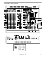
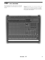
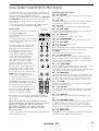
stereo powered mixer
716 S
716 S
stereo powered mixer
ENGLISH
FRANÇAIS
5 - 10
11 - 16
APPENDIX
specifications
block diagram
connections
example of connection
17 - 23
FRONT and REAR PANELS
34 27
STEREO EFF. RET.
XLR IN
pin 1 - GND
pin 2 pin 3 -
PHANTOM
EFF.SEND 1
EFF. 1
MUTE
EFF.SEND 2
EFF. 2
MUTE
2
3
4
5
6
7
8
9/10
9
MIC.
MIC.
LINE
MIC.
LINE
MIC.
LINE
MIC.
LINE
MIC.
LINE
18
MIC.
LINE
11/12
13/14
35
L
R/(MONO)
2
R
R
R
R
L
(mono)
L
(mono)
L
(mono)
L
(mono)
LINE
LINE
LINE
LINE
MIC.
LINE
ON
15/16
LINE
L
4
1
6
4
3
2
1
7
8
9
10
GAIN
-0+
2
15
H.F.
10
-0+
2
4
8
12
15
15
H.F.
.75
1.6
.18
1.6
.3
2
3 KHz
FREQ.
-0+
2
2
4
4
8
8
12
12
15
15 dB
.18
-0+
2
2
4
4
8
8
12
12
15
15 dB
L.F.
15
4
3
10
5
3
2
1
7
8
9
0
4
10
5
1
4
5
1
7
8
9
L
PAN
4
7
8
9
L
PAN
1
4
1
6
7
8
9
L
R
peak
PAN
5
4
1
7
8
9
L
PAN
3
1
6
7
8
9
L
R
peak
PAN
4
1
L
PAN
5
5
6
B
15
14
7
8
9
5
L
R
peak
PAN
6
15
4
7
8
9
10
-0+
6
4
3
2
1
7
8
9
10
GAIN
-0+
15
2
-0+
-0+
15
15
-0+
15
L.F.
15
5
4
6
5
4
1
5
2
1
10
5
4
5
6
7
8
9
5
6
6
3
3
0
0 dB
6
3
3
3
6
6
9
9
9
12
12
12
15
15
15
18
18
18
10
10
5
B
5
7
8
9
9
6
3
5
6
3
2
1
7
8
9
GAIN
4
ON
A
5
effect 1
9
12
B
4
7
8
9
0
10
3
2
1
B
7
15
16
L
L
R
peak
PAN
BAL
8
L
R
peak
BAL
9/10
L
R
peak
BAL
11/12
25
L
R
peak
BAL
13/14
L
R
peak
L
R
BAL
BAL
BAL
E2
E1
15/16
L
R
1
L
R
peak
29
10
5
BAL
STEREO EFFECTS
RETURNS
125
2
2
-0+
H.M.
2
2
4
8
12
H.M.
2
4
8
12
15
-0+
L.M.
A
2
4
7
8
9
10
0
2
4
4
8
12
5
B
L
MASTER
6
6
6
6
6
6
6
6
6
6
6
6
6
6
6
6
6
+
0
+
0
+
0
+
0
+
0
+
0
+
0
+
0
+
0
+
0
+
0
+
0
+
0
+
0
+
0
+
0
+
0
6
6
6
6
6
6
6
6
6
6
6
6
6
6
6
6
6
6
18
18
18
18
18
17
6
18
18
18
18
18
18
18
18
18
18
18
18
18
18
30
30
30
30
30
30
30
30
30
30
30
30
30
30
30
30
30
30
30
40
40
40
40
40
40
40
40
40
40
40
40
40
40
40
40
40
40
40
MANUFACTURED AND MADE IN ITALY BY
220V-240V
50 60Hz
48
7
8
9
42
44
43
45
R
PHONES OUT
600
52
40
48
L
POWER
6
10
0
PHONES
200
38
5
3
2
1
MONO
+
0
716S
4
7
8
9
10
0
6
46
6
3
2
1
15
L.F.
MONITORS
6
3
2
1
TAPE
IN
15
-0+
5
+
0
54 53
51
R
FLAT
EQ
37
-0+
15
L.F.
L
Hz
2
4
8
12
15
16K
15
4
8
12
2
4
8
12
15
-0+
15
2
4
8
12
8K
R
4
8
12
15
2
4
8
12
15
4K
4
8
12
2
4
8
12
L.M.
H.F.
2K
2
6
26
TAPE
IN
OUT
15
15
2
15
-0+
1K
-0+
4
8
12
4
8
12
15
500
2
4
8
12
4
8
12
6
R
peak
250
2
15
15
2
10
-0+
4
8
12
H.F.
30
31
32
5
63
6
10
7
8
9
0
M
R
peak
31
6
7
8
9
0
4
6
3
2
1
effect 2
0
3
2
1
A
5
7
8
9
GAIN
10
5
3
2
1
6
7
8
9
0
4
6
10
6
12
4
10
0
3
2
1
ON
3
9
L
6
7
8
9
41
0 dB
3
33
MOD.
12
3
Hz
4
10
R
6
6
7
8
9
0
L
6
10
5
B
9
dB 0
6
3
2
1
B
STEREO
EXTERNAL
EFFECTS
6
12
7
8
9
0
4
10
6
3
2
1
A
6
3
2
1
0
EXTERNAL
EFFECTS SEND
7
8
9
4
7
8
9
0
4
5
4
3
2
1
flat
tone
6
6
3
7
8
9
0
9
dB 0
20
5
3
2
1
A
7
8
9
0
10
20
10
3
2
1
2
3
10
4
3
2
1
flat
tone
6
3
2
1
1
10
7
8
9
10
10
0
5
9
A
3
4
7
8
9
0
4
7
8
9
0
5
24
6
3
2
1
2
B
10
5
0
+ 3
dB 0
6
3
2
1
6
7
8
9
4
7
8
9
0
5
0
6
3
2
1
10
4
3
2
1
15
3
2
1
4
10
5
+ 3
2
4
8
12
INPUT LEVEL
dB 0
15
-0+
23
A
6
7
8
9
0
B
10
4
10
5
3
2
1
6
7
8
9
0
4
7
8
9
0
10
6
INPUT LEVEL
4
8
12
15
22
PROGRAM
2
2
4
8
12
L.F.
7
8
9
0
4
7
8
9
0
5
3
2
1
A
6
3
2
1
6
3
2
1
2
B
6
10
5
10
5
3
2
1
7
8
9
4
7
8
9
5
0
4
7
8
9
0
4
10
3
2
1
1
A
6
7
8
9
0
6
3
2
1
10
5
5
4
7
8
9
0
3
2
1
B
10
0
6
3
2
1
6
10
5
-0+
15
PROGRAM
6
716 S
39
9
10
15
21
2
4
8
12
4
8
12
Montarbo
36
7
8
9
0
3
2
1
2
4
8
12
M.F.
2
4
8
12
-0+
15
2
4
8
12
4
5
3
2
1
1
4
4
8
12
H.F.
15
-0+
7
8
9
10
19
20
2
MONO OUT
R
49
STEREO DIGITAL
EFFECTS PROCESSOR
6
3
2
1
2
15
15
2
4
8
12
2
4
8
12
M.F.
2
4
8
12
L.F.
2
5
GAIN
4
8
12
15
H.F.
15
-0+
4
8
12
2
4
8
12
15
2
15
2
15
4
8
12
M.F.
4
8
12
15
2
4
8
12
2
15
4
8
12
L.F.
H.F.
2
4
8
12
2
-0+
2
4
8
12
15
15
4
7
8
9
0
M
2
4
8
12
M.F.
A
10
3
2
1
2
H.F.
6
7
8
9
0
4
-0+
4
8
12
4
10
5
3
2
1
1
2
4
8
12
6
7
8
9
0
4
6
3
2
1
GAIN
5
15
5
4
10
0
4
8
12
3
2
1
6
10
3
2
1
2
A
7
8
9
M
R
peak
5
2
3
2
1
13
10
0
4
7
8
9
6
7
8
9
0
-0+
4
6
10
5
3 KHz
FREQ.
4
8
12
L.F.
7
8
9
0
4
10
0
M
5
3
2
1
6
3
2
1
2
B
10
5
.18
-0+
2
2
4
4
8
8
12
12
15
15 dB
LEVEL
15
7
8
9
10
2
2
3
2
1
6
7
8
9
4
10
0
M
R
peak
5
5
0
15
4
7
8
9
4
1.6
MID.
4
3
2
1
2
2
3
2
1
A
6
10
-0+
4
8
12
4
7
8
9
0
12
4
8
12
L.F.
10
5
.75
3 KHz
FREQ.
-0+
2
2
4
4
8
8
12
12
15
15 dB
6
3
2
1
10
3
2
1
2
B
6
7
8
9
4
10
0
5
5
3
2
1
10
0
15
0
4
7
8
9
0
3
2
1
6
3
2
1
2
B
10
A
6
3
2
1
6
7
8
9
0
4
10
0
5
3
2
1
M
2
7
5
3
2
1
2
M
R
peak
B
10
10
15
15
.3
LEVEL
3
2
1
10
5
.18
MID.
2
4
8
12
4
6
7
8
9
0
4
7
8
9
0
5
L.F.
1.6
2
2
4
8
12
15
4
8
12
15
6
5
2
4
8
12
H.F.
5
GAIN
1.3
.75
LEVEL
-0+
15
.3
3 KHz
FREQ.
-0+
2
2
4
4
8
8
12
12
15
15 dB
2
3
2
1
A
6
3
2
1
6
7
8
9
0
1
10
0
5
3
2
1
6
3
2
1
2
M
5
6
5
4
10
0
4
10
4
6
10
5
.18
MID.
4
8
12
15
1.6
2
2
4
8
12
L.F.
7
8
9
0
4
10
15
5
3 KHz
FREQ.
-0+
1.3
.75
-0+
2
2
4
4
8
8
12
12
15
15 dB
-0+
15
H.F.
.3
LEVEL
3
2
1
A
6
7
8
9
0
B
7
8
9
0
10
5
3
2
1
6
3
2
1
6
3
2
1
2
5
4
10
10
4
6
7
8
9
0
4
.18
MID.
2
4
8
12
15
1.6
2
2
4
8
12
L.F.
15
4
7
8
9
10
2
4
8
12
6
3
2
1
GAIN
2
4
8
12
1.3
.75
3 KHz
FREQ.
-0+
2
2
4
4
8
8
12
12
15
15 dB
-0+
15
H.F.
4
7
8
9
-0+
5
11
10
2
4
8
12
6
3
2
1
GAIN
2
4
8
12
15
.3
LEVEL
3
2
1
A
6
7
8
9
0
B
7
8
9
0
10
5
3
2
1
6
3
2
1
7
8
9
0
4
.18
MID.
2
15
5
1.6
2
2
4
8
12
4
6
3
2
1
A
6
-0+
4
8
12
15
4
8
12
15
H.F.
-0+
2
5
4
7
8
9
10
1.3
.75
3 KHz
FREQ.
-0+
2
2
4
4
8
8
12
12
15
15 dB
L.F.
15
.3
LEVEL
15
5
4
7
8
9
0
4
.18
MID.
2
4
8
12
15
L.F.
1.6
2
2
4
8
12
6
3
2
1
A
B
4
15
5
-0+
2
4
8
12
15
H.F.
6
3
2
1
GAIN
2
4
8
12
1.3
.75
LEVEL
2
4
8
12
15
.3
3 KHz
FREQ.
MID.
LEVEL
-0+
15
H.F.
-0+
5
4
7
8
9
10
2
4
8
12
6
3
2
1
GAIN
2
4
8
12
1.3
.75
2
2
15
-0+
5
4
7
8
9
10
2
4
8
12
6
3
2
1
GAIN
2
4
8
12
1.3
.3
MID.
-0+
5
4
7
8
9
10
2
4
8
12
6
3
2
1
GAIN
2
4
8
12
1.3
2
4
7
8
9
2
4
8
12
6
3
2
1
GAIN
5
INSERT
50
28
5
PHANTOM
48 V DC
ON
A MONITORS B
47
5
2 x 350W Stereo Powered Mixer
&
2 x160 - Programs
Montarbo Digital Effects Processor
48V.
1
1
10
8
OUTPUTS
R
ELETTRONICA
Montarbo
I
350 W
s.r.l.
CAUTION !
AVIS !
TO PREVENT ELECTRICAL SHOCK,
DO NOT REMOVE COVERS
TO PREVENT RISK OF FIRE ALWAYS REPLACE
FUSES WITH SAME TYPE AND RATINGS
THIS APPARATUS MUST BE EARTHED
POUR PREVENIR TOUT RISQUE DE FEU REPLACER
^
TOUJOURS UN FUSIBLE DE MEME CARACTERISTIQUES
^
CET APPAREIL DOIT ETRE RELIE` A LA TERRE
POUR PREVENIR TOUT RISQUE DE CHOC
ELECTRIQUE, NE PAS OUVRIR
O
FUSE
F 6,3A
4
Pin 1 - GND
Pin 2 - signal
Pin 3 - n.c.
( min. load )
Montarbo
350 W
4
( min. load )
Pin 1 - GND
Pin 2 - signal
Pin 3 - n.c.
2 x 350W
STEREO POWERED MIXER
I.E.C. power supply socket:
fuse replacement
service fuse
reserve fuse
3
716 S
stereo powered mixer
The powered mixer 716S is compact and easy to install and
operate everywhere, it can be hooked up to your system in
a breeze.
La table de mixage amplifié 716S est synonyme de rationalité et de
rendement.
Caractérisé par une riche dotation de commandes et une grande
puissance de sortie, 716S réunisse la qualité sonore et la fiabilité
dans un système compact qui garantit les meilleures performances
de la plus grande facilité d'utilisation.
4
716 S
stereo powered mixer
The lighting flash with arrowhead symbol within an equilateral triangle, is intended
to alert the user to the presence of uninsulated "dangerous voltage" within the
product's enclosure, that may be of sufficient magnitude to constitute a risk of
electric shock to humans.
The exclamation point within an equilateral triangle, is intended to alert the user
to the presence of important operating and maintenance (servicing) instructions.
IMPORTANT ! Safety instructions
WARNING !
In order to protect your own and others' safety and to avoid
invalidation of the warranty of this product, please read this
section carefully before operating this product.
- This product has been designed and manufactured for being operated as
powered mixing console in the applications tipical of a sound reinforcement system or of a sound recording system. Operation for purposes and
in applications other than these has not been covered by the manufacturer
in the design of the product, and is therefore to be undertaken at end
user's and/or installer's sole risk and responsability.
To avoid the risk of fire and/or electric shock:
• Never expose this product to rain or moisture, never use it in proximity of
water or on a wet surface. Never let any liquid, as well as any object, enter
the product. In case, immediately disconnect it from the mains supply and
refer to servicing before operating it again.
• Before connecting this product to the mains supply, always make sure
that the voltage on the mains outlet corresponds to that stated on the
product.
• This product must be connected only to a grounded mains outlet
complying to the safety regulations in force via the supplied power cable.
In case the power cable needs to be substituted, use exclusively a cable of
the same type and characteristics.
• Never place any object on the power cable. Never lay the power cable
on a walkway where one could trip over it. Never press or pinch it.
• Never install the product without providing adequate airflow to cool it.
Never obstruct the air intake openings on it.
• In case the external fuse needs replacement, substitute it only with one
of the same type and rating, as stated on the product.
• Always make sure the On/Off switch is in its 'Off' position before doing
any operation on the connections of the product.
• Before attempting to move the product after it has been installed,
remove all the connections.
• To disconnect the power cable of this product from the mains supply
never pull the cable directly instead, hold the body of the plug firmly and
pull it gently from the mains supply outlet.
ENGLISH
CONTENTS
3
Front and rear panels
__________________________________________
4
Introduction
__________________________________________
__________________________________________
6-8
Controls and connections
__________________________________________
9
Important !
__________________________________________
9
Stereo graphic equalizer
__________________________________________
10
Dual stereo multieffect DSP
__________________________________________
17 - 23
Appendix:
__________________________________________
18
◗ Technical specifications
__________________________________________
19
◗ Block diagrams
__________________________________________
20 - 22
◗ Connections
__________________________________________
23
◗ Connection example
__________________________________________
CAUTION !
This product does not contain user serviceable parts.
To prevent fire and/or electrical shock, never remove its cover.
Maintenance and servicing must be carried out only by
Elettronica Montarbo srl or the official Montarbo Distributor
in your State or by qualified personnel specifically authorized
by them.
- Before placing the product on a surface of any kind, always make sure
that its shape and load rating will safely match the product's size and
weight.
- To avoid shocks always reserve a protected area with no access to unqualified
personnel as installation site of the product. In case the product is used near
children and animals closest supervision is necessary.
- This product in combination with headphones or speakers can generate
very high acoustic pressures which are dangerous for the hearing system.
Do not operate for a long period of time at a high or unconfortable volume
level. Never expose children to high sound sources.
5
CONTROLS AND CONNECTIONS
MONO INPUT CHANNEL
STEREO INPUT CHANNEL
1 ➤ GAIN: adjust the gain (sensitivity) of the line and mic inputs,
allowing connections of signal sources (both line and mic level)
having a wide range of signal level. As a practical rule, the GAIN
control must be set to the maximum allowable level that will not
activate the peak level indicator. This will maximize the signal to
noise ratio.
11 ➤ GAIN: same as in the mono channel.
2 ➤ H.F / MID FREQ. / MID LEVEL / L.F: 3-band equalizer with
parametric control of the mid range. While the High and Low
controls act on fixed frequency cuts, the Mid control allows to
choose the frequency to be lowered or raised.
H.F: adjusts the amount of boost or cut in the high frequency
range. Turning the control clockwise increases the amount of high
frequencies, counter-clockwise decreases it.
MID FREQ.: chooses the frequency to be lowered or raised.
MID LEVEL: adjusts the amount of boost or cut in the frequency
choosen by means of the MID FREQ. control.
Note: If the MID LEVEL control is set at '0' (centre) there will be no alteration in
the mid frequency band (independently of the MID FREQ. control setting).
L.F: adjusts the amount of boost or cut in the low frequency range.
Turning the control clockwise increases the amount of low frequencies, counter-clockwise decreases it.
3 ➤ A / B: monitor sends volumes (pre fader, post tone controls).
They set the level of that input channel in the monitor outputs.
12 ➤ H.F / M.F / L.F.: 3-band equalizer.
H.F: adjusts the amount of high frequencies giving up to 15dB of
boost or cut at 15kHz.
M.F: adjusts the amount of mid frequencies giving up to 15dB of
boost or cut at 600Hz.
L.F: adjusts the amount of low frequencies giving up to 15dB of
boost or cut at 50Hz.
Note: Turning the control clockwise increases the amount of high, mid or low
frequencies, counter-clockwise decreases it. The reaponse is flat at the center
position.
13 ➤ A / B: same as in the mono channel.
14 ➤ 1 / 2: same as in the mono channel.
15 ➤ BAL: stereo balance. Allows to adjust the level of the input
signal in the left or right master outputs. If the channel is used as
a mono channel it becomes a PAN control.
16 ➤ PEAK: same as in the mono channel.
17 ➤ Channel VOLUME fader.
● connections:
18 ➤ L/R: unbalanced jack line inputs for stereo instruments.
For 'mono' connections use 'L / mono' input.
4 ➤ 1 / 2: effect sends volumes (post fader and post tone controls).
They adjust the quantity of channel signal that is sent both to the
correspondent built-in effect and to an external effect connected
to the 'EFF SEND 1/2' and to the 'STEREO EFF. RET. 1/2' sockets.
Note: On the channels where you don't want to have neither the internal effect
nor the external effect, turn these knobs fully anticlockwise.
Should the external effect only be required, then turn off the internal effect.
5 ➤ PAN: this control allows to place the channel’s input signal
within the stereo image by assigning more or less of the signal
to the left or right master volume controls.
6 ➤ PEAK: peak LED indicator. It lights when the signal level is
approaching the maximum (clipping) allowable level. The signal
is sampled in two points of the channel's signal path: • after the
input amplifier (micro and line); • after the equalizer.
If the LED is continuously lighted, you must reduce the input GAIN
or modify the equalizer settings, reducing the boost introduced by
the level controls HF, MID LEVEL and LF.
7 ➤ Channel VOLUME fader.
8 ➤ PHANTOM 48V DC: pushbutton for on/off switching of the
48V phantom power supply on the channels 5, 6, 7, 8 (the phantom
power supply allows use of condenser microphones).
Note: Before pushing this button, make sure that the unit is turned off or that
all the slider controls are to their lowest settings.
● connections:
9 ➤ MIC: balanced XLR microphone input (for microphones).
10 ➤ LINE: unbalanced jack line input (for instruments and high
level sources).
Note: Do not use both the MIC and the LINE input of one channel at the
same time).
Do not connect instruments or other high level sources to the MICRO inputs
(this will result in distortion due to excessive signal level).
Do not connect microphones to the LINE inputs (the resulting signal will be
of low level and low quality) .
6
CONTROLS AND CONNECTIONS
DUAL MULTIEFFECT DSP
EXTERNAL EFFECTS SENDS AND RETURNS
With 56-bit internal DSP and 24-bit Delta-Sigma conversion, the
two internal effects (160 programs each) provide high performance
digital audio processing combined with extremely easy operation.
28 ➤ 1 / 2 external effects sends: level controls for the external
effects sends. They are the mixes of the signals sent from '1' and
'2' sends volumes on each channel and set the level of the signal
appearing at the 'EFF SEND 1' and 'EFF SEND 2' jack outputs.
19 ➤ Program LED display: shows the number of the currently
selected program.
20 ➤ PROGRAM: program selection keys allow to select any
memory number to call one of the 160 programs available.
▼ = decrement key
▲ = increment key
21 ➤ INPUT LEVEL: 5-segment input level LED indicator.
A good setting of the effect sends (1 and 2) on each channel will
produce continuous lighting of the green LED segments, while the
red segment must flash only occasionally.
☞ If the red LED is continuously lighted it indicates signal overload
and it is necessary to reduce the effect send volumes (1 and 2)
on individual channels.
22 ➤ TONE control: Turning this control clockwise produces a
gradual decrease in high frequencies. Fully anticlockwise the
response is flat.
23 ➤ A / B: monitor sends. Allow to adjust the level of the stereo
effect in the monitor mixed outputs 'A' and 'B'.
24 ➤ ON: effect on/off button, with green LED indicator.
25 ➤ BAL: balance. Allows to adjust the level of the stereo signal
in the L and R master outputs.
26 ➤ VOLUME fader.
● connections:
27 ➤ EFF 1 - EFF 2 / MUTE: jack sockets for connection of remote
footswitches. They allow remote control enabling/disabling of the
built-in effect processors. This is possible only when the "ON"
buttons are pushed.
The 'Mute' LED indicator lights when the effect is off.
Each one of the two STEREO RETURNS features
29 ➤ GAIN: adjusts the gain (sensitivity) of the effect return.
30 ➤ A / B: monitor sends controls. Set the level of the external
effect to be sent to the A and B monitor outputs.
31 ➤ BAL: stereo balance of the external effect. Allows to adjust
the level of the stereo signal of the effect in the L and R master
outputs.
32 ➤ PEAK: peak LED indicator.
33 ➤ VOLUME fader.
● connections:
34 ➤ EFF SEND 1/2: jack output sockets for the external effects
sends.
35 ➤ STEREO EFF RET 1/2: jack inputs for the external effects
returns.
■ Connect the inputs of the external effects to the EFF SEND 1/2
output sockets.
■ Connect the L and R outputs of the stereo external effects to the
L and R 'EFF RET 1' and 'EFF RET 2' inputs.
• For a mono effect connect its 'only effect' output to the 'R / mono' socket.
■ Use the controls 1 and 2 on each channel to determine the
quantity of channel's signal to be sent to the external effects, the
EXTERNAL EFFECTS SEND 1 and 2 controls (28) to determine the
quantity of signal to be sent to the EFF SEND 1 and 2 outputs, and
the GAIN, A, B and BAL (29, 30, 31) controls, of the 'stereo effects
returns' section, to adjust the effect return level in the 'A' and 'B'
monitor outputs and in the 'L' and 'R' master outputs.
In the channels where one or both external effects are not desired,
turn the correspondent control fully anticlockwise.
Note: The stereo inputs EFF RET 1 and 2 are normal stereo line inputs. You can
thus use them to connect any line signal (such as the L/R outputs of a second
mixer, instruments, expanders…).
☛ see fig. 4 page 22
7
CONTROLS AND CONNECTIONS
MASTER SECTION:
36 ➤ A / B: two 10 segment LED arrays give istantaneous reading
of A and B outputs levels.
37 ➤ HF / HM / LM / LF: 4-band equalizer.
• HF: adjusts the amount of high frequencies.
•HM and LM: adjust the amount of mid-high and mid-low frequencies.
• LF: adjusts the amount of low frequencies.
38 ➤ A/B MONITORS: volume faders for the A and B monitor
outputs.
39 ➤ L / R: two 10 segment LED arrays give istantaneous reading of
L and R outputs levels.
40 ➤ L/R MASTER: volume faders for the left and right master
outputs.
41 ➤ 10-band stereo graphic EQUALIZER.
42 ➤ EQ/FLAT: equalizer on/off switch.
43 ➤ MONO: level control for the mono preamplifier output
(pre-master).
44 ➤ TAPE IN: sets the level of the signal at the 'Tape in' socket of
the mixer.
45 ➤ PHONES: level control for the phones output.
46 ➤ POWER: mains power switch.
● connections:
47 ➤ A / B monitors: A and B monitor outputs with jack sockets.
■ Connect the A and B output sockets to the inputs of the self-
powered stage monitors. Adjust the A and B monitor send controls
on each channel, the tone controls (37) and the volume faders (38)
on the 'MONITORS' section. Each output can drive up to 10 parallel
connected powered monitors.
☛ see fig. 2 page 21
48 ➤ OUTPUTS L/R: output sockets for the internal power amplifiers.
Miniumum load impedance for each amplifier is 4Ω.
■ Connect one or two 8 Ohms speakers to each output.
Never use the internal power amplifiers with loads below 4 Ohms.
Adjust the volume fader on each channel as well as the L/R master
volume faders.
Note: Each output is fitted with 2 jack and 1 XLR sockets (parallel connected)
and features electronic and thermal protections, delayed power-up sequence,
automatic trouble-shooting and forced cooling.
☛ see fig. 1 page 20
49 ➤ L/R INSERT: these stereo jack sockets allow to connect an
external equipment (e.g. a graphic equalizer, a limiter, an audio
processor) directly to the L/R master outputs. They are post-master
controls.
☛ see fig. 3 A page 21
These sockets can also be used as preamp-outputs for connecting
powered speakers or external power amplifiers. It is possible to use
the line and power outputs at the same time. Take out the signal
from the insert sockets by means of two stereo jack plugs, in which
you have previously joined the RING with the TIP (see example in
page 49) and send it to the inputs of the active speakers by means
of mono jack plugs.
☛ see fig. 3 B page 21
Note: If you plug mono jack into the stereo insert sockets, the power outputs are
automatically excluded.
50 ➤ MONO: mono output (pre-master) for the connection to
mixers, studio consoles or any auxiliary equipment, external power
amplifiers or powered speaker enclosures. The mono output is not
affected by the master controls and has its own volume control.
☛ see fig. 5 page 22
51 ➤ L/R TAPE IN/OUT: PIN in-out sockets. They allow connection
to stereo tape recorder.
■ Connect the L/R TAPE OUT sockets to the inputs of the tape recorder (line in) and the outputs of the tape recorder (line out) to
the L/R TAPE IN sockets of the mixer. If the TAPE IN inputs are not
used, it is suggested to keep the volume control fully closed, to
keep output noise to the minimum value.
■ For playback: switch the recorder to play and adjust the TAPE IN
volume control on the mixer (and the output volumes of the tape
recorder, if available).
■ For recording: switch the recorder to the 'record' mode and
adjust the input volume of the tape recorder. Set the output
volume control of the tape recorder to its lowest setting. In case
your tape recorder has no output volume control, disconnect the
cables from the TAPE IN sockets. The signal sent to the tape
recorder is unaffected by the L/R master faders settings.
Note: The L/R Tape inputs accept any line signal. You can thus use them as 2
extra line inputs to connect instruments, expanders or the L/R outputs of a mixer.
☛ see fig. 6 page 22
52 ➤ PHONES OUT: output for stereo phones.
53 ➤ I.E.C power supply socket and mains fuse.
54 ➤ Auxiliary GROUND socket.
8
IMPORTANT!
CARE AND MAINTENANCE
☞ Never expose the mixer to heat sources such as radiators or other
products that produce heat.
☞ Never expose the mixer to direct sunlight, excessive vibrations or
mechanical shocks.
☞ Avoid operating and storing the mixer in damp or dusty places:
this will avoid malfunctions, premature degrading of specifications.
☞ Avoid using the mixer close to strong sources of electromagnetic
interferences (e.g. video monitors, high power electrical cabling).
This may lead to degradation of audio quality.
☞ Take care of the connectors cables, always coil them avoiding
knots and twists.
☞ Care should be taken so that objects do not fall and liquids are
not spilled into the mixer. In public event don't let people, musicians,
technicians or anyone put glasses, cups, ashtrays and cigarettes on
the mixer.
☞ Never apply excess force to the controls (knobs, sliders,
potentiometers).
☞ Use soft brush or a jet of air to clean the panel.
Do not use alcohol, solvents or detergents.
☞ If service is needed, refer to qualified service personnel only or
to the Montarbo distributor in your country.
INSTALLATION AND USE
☛ When connecting the mixer to the mains supply: • check that
mains voltage corresponds to the voltage indicated on the panel;
• use the 3-wire power cord supplied; • always connect it to a
grounded outlet.
☛ Always use quality cables and connectors.
☛ Use shielded cables for your connections to the micro and line
inputs, to the send/return sockets, to the monitor outputs, to the
tape in/out and L/R insert sockets and to the mono output.
☛ Use unshielded cables for the connection of passive speaker
enclosures to L/R powered outputs. Never operate the internal
power amplifiers with loads below 4 ohms each.
☛ Before switching on or off the mixer, 'close' (set to minimum the
outputs faders) the master outputs. This will avoid switching noises
that may cause damages to loudspeakers.
PRELIMINARY CONNECTIONS AND SETTINGS
❉ Connect the speaker enclosures, the microphones, the instruments.
❉ Before turning on the mixer, set the channel volume faders and
the master volume faders to their lowest settings and the sliders of
the graphic equalizer to the zero mark (center).
❉ Switch on the unit and turn the gain controls to their lowest
settings, the tone controls and panpots to the middle position, and
the monitor and effect sends anti-clockwise to their lowest settings.
☛ To optimize dynamics of each channel according to the various
signal sources, proceed as follows: • using a microphone (connected
to the XLR mic input) in conditions typical of the intended use, set
the GAIN control so as to cause the peak LED to illuminate; • now
reduce the GAIN just enough until the peak LED switches off and
adjust the volume. ☛ The channel's peak LED is affected only by
the GAIN control and the TONE controls.
Note: Repeat the above procedure for all the channels, one at a time, using the
signal source assigned to that channel and simulating real operating conditions
as closely as possible.
❉ Set the volume faders of the L/R master outputs and of the
internal effects near to the "0" setting and the monitor volume
controls to the middle position, and now adjust the volume of
each channel according to your requirements .
STEREO GRAPHIC EQUALIZER
Careful use of the graphic equalizer can help the overall system
sound more natural in less than perfect acoustic environments and
allows to reduce feedback. For a proper setting of the controls of
the graphic equalizer consider the following:
• Avoid settings with all sliders up or all sliders down. This would
involve a useless increase in noise or a reduction of dynamic range.
• Choose carefully the placement of loudspeakers and microphones to minimize feedback before using the equalizer, in order to
get the most volume before feedback is heard. Otherwise you risk
removing significant amounts of your program material and altering
too much your sounds.
• With the graphic equalizer’s controls set to the zero mark
(centered) adjust the tone controls of each channel until you get
the tonal color you want for each microphone or instrument.
Once you have adjusted the tone controls of each channel, start
adjusting the controls of the graphic equalizer to compensate for
the acoustic environment and speaker placement.
This will allow you to compensate for different acoustic environments acting only on the equalizer’s setting with no need of
altering too much the tone controls settings of each channel.
12
12
12
12
9
9
9
9
6
6
6
6
3
3
3
3
dB 0
0 dB
0 dB
dB 0
3
3
3
3
6
6
6
9
9
9
9
12
12
12
12
Hz
31
63
125
250
500
1K
2K
4K
8K
16K
6
Hz
31
63
125
250
500
1K
2K
4K
8K
16K
9
DUAL STEREO MULTIEFFECTS PROCESSOR
The built-in effects processor has been designed for maximum ease
of use. It sports a wide range of high quality programs, all carefully
tailored to today’s music production requirements.
At startup, programs 45 and 55 are auto-loaded: these ECHO+REV.
and VOICE REV. effects provide good results in the most different
music styles, so you will maybe want to use them as general
purpose effects.
To select the programs, you simply use the ▲ and ▼ pushbuttons
to scroll through programs up and down, respectively.
EFFECTS SETUP
STEREO DIGITAL
EFFECTS PROCESSOR
1 – Switch Effect 1 and Effect 2 to operation
by pushing their ON buttons.
A green LED lights up on each processor to
signal its status.
2 – Bring the effects faders E1/E2 and the L/R
master faders near to the '0' position on their
scale (at working level).
3 – Set the channel volume and the effects
sends levels with 1 and 2 controls on the
input channels you wish to add effects to.
4 – Carefully inspect the input levels on
the LED bargraphs of both processors:
• the red LEDs should blink occasionally
• if the red LEDs are constantly lit, you
could suffer severe distortion on the
effect signal. This isn’t due to the processor
itself, rather it is common on digital
processors of any price because of the
digital technology itself. In case, reduce
the levels of the 1 and 2 controls on the
input channels until the red LEDs of LED
bargraph light up only on loudest peaks.
5 – You can alter the effect timbre with the
TONE control on the effects processor:
turn it clockwise to 'brighten' the effects,
or counter-clockwise to 'darken' it.
6 – Route the effects to the main outputs
with the BAL control, and/or to the stage
monitors with the A and B controls, then set
their volume faders at the desired levels.
7 – Select the program you wish to use on
both processor with the ▼ and ▲ buttons.
Use the chart on the next column as a
reference to recognize the programs.
PROGRAM
PROGRAM
INPUT LEVEL
INPUT LEVEL
+ 3
+ 3
dB 0
dB 0
3
3
10
10
20
4
3
2
1
flat
tone
4
20
5
5
6
0
4
7
8
9
3
2
1
4
10
5
A
7
8
9
0
10
5
6
7
8
9
5
6
7
8
9
0
4
6
3
2
1
B
4
3
2
1
flat
tone
6
3
2
1
A
7
8
9
10
5
6
7
8
9
3
2
1
B
0
10
ON
ON
effect 1
effect 2
L
L
R
BAL
R
BAL
E2
E1
6
6
+
0
+
0
6
6
18
18
30
30
40
40
■ We suggest you start from the following program numbers so
you can listen to the most representative effects of each available
effect ranges.
05 (STEREO GEN), 20 (HALO), 35 (ECHO), 47 (ECHO + REVERB),
57 (VOICE REVERB), 66 (PERCUSSION REVERB), 75 (HALO + REVERB),
86 (PING PONG), 89 (BOUNCE), 93 (EARLY REFLECTIONS),
A9 (STEREO FLANGER), B3 (STEREO CHORUS), C5 (DETUNE),
D5 (DUAL PITCH), D9 (SINGLE PITCH), E8 (PITCH + REVERB),
F2 (REVERSE REVERB).
Feel free to experiment with any program until you get the sounds
that most satisfies your taste.
Programs and effects description
00 → 09 STEREO GEN.
Adds a short delay to the signal to create a pseudo-stereo effect out of
mono sources.
10 → 29 HALO
It’s a digital recreation of the effect built in the Montarbo reverb units
of the sixties, a vintage classic that never went out of fashion.
30 → 39 ECHO
Classic multiplex effect. Delay time increases with program number.
40 → 49 ECHO + REVERB
Delay and reverb blended together make for the impressive effect you
can listen on most contemporary productions.
50 → 59 VOICE REVERB
Reverbs specially tailored to enhance vocals’ character.
60 → 69 PERCUSSION REVERB
Ambience effects that enrich both acoustic and electronic percussions.
70 → 79 HALO + REVERB
Halo and reverb effects blended together.
80 → 88 PING PONG
Basically an auto-panned delay, popular on many rock hits, the samples
are being routed alternatively to full left and full right master.
89 BOUNCE
Repeats start widely spaced to become closer and closer.
90 → 99 EARLY REFLECTIONS
Generates the initial part of the reverb without the decaying 'tail' of
the effect. It makes for thicker and more aggressive sound without
increasing its decay time. Usually it is used to colour vocals or horns
solos in contemporary productions.
A0 → A9 STEREO FLANGER
It may be considered as a very intense chorus, with two voices crossing
their stereo image and with feedback acting as 'comb filter'.
The frequencies corresponding to the filter's notches and peaks change
continuously, producing thus the typical flanging sound.
B0 → B9 STEREO CHORUS
It produces a warm and rich sound. Three voices are derived from the
input signal and are sent to the Left and Right channels and to the center.
The result is that even the thinner voice will sound like an ensemble.
It is ideal to enliven a guitar accompainment and to 'fatten' a voice.
C0 → C9 DETUNE
Slightly alters the tuning of the source to simulate a 'doubling' effect
with increased tuning alterations.
D0 → D5 DUAL PITCH
A wonderful 'harmonizer' with two voices trasposing the input signal
pitch in real-time. Your voice will be automatically accompanied by a
chorus.
D6 → D9 SINGLE PITCH
'Harmonizer' with one voice trasposing the input signal pitch in realtime.
E0 → E9 PITCH CHANGE + REVERB
It's the combination of the two effects which most of all let your voice
sound warmer and thicker. Beside your voice, the Pitch Change
provides a voice in the center of the stereo image. To the resulting
'harmonizer' effect a warm Plate type Reverb effect, particularly suited
for voice, is added in cascade.
F0 → F9 REVERSE REVERB
Unmistakably a 'must' of many 80's records, starts at low level, builds
up and quit abruptly. Usually served with percussion.
10
716 S
stereo powered mixer
Le symbole représentant un éclair se terminant par une flèche dans un triangle
équilatéral indique la présence dans le boîtier d'un 'voltage dangereux' non isolé,
suffisamment important pour constituer un risque d'électrocution.
Le symbole représentant un point d'exclamation dans un triangle équilatéral renvoie
l'utilisateur à des instructions importantes relatives au fonctionnement et à l'entretien
de l'appareil.
IMPORTANT ! Normes de securité
ATTENTION !
Dans l'intérêt de la sécurité personnelle et des tiers, et pour ne
pas invalider la garantie, nous recommandons de lire
attentivement ces recommandations avant d'utiliser le produit.
- Cet appareil a été conçu et construit pour être utilisé en tant que table
de mixage amplifié dans le contexte typique d'un système d'amplification
sonore et/ou d'un système d'enregistrement sonore. L'utilisation pour des
objectifs différents de ceux-ci n'est pas contemplée par le constructeur et
s'effectue par conséquent sous la responsabilité directe de l'utilisateur/
installateur.
Pour eviter le risque d'incendie et/ou d'electrocution:
• Ne pas exposer le produit à la pluie, ne pas l'utiliser en présence d'humidité élevée ou près de l'eau. Ne pas laisser pénétrer de liquide à l'intérieur
de l'appareil, ni aucun autre objet solide. Dans le cas contraire déconnecter immédiatement l'appareil du réseau électrique et s'adresser à un service d'assistance qualifié avant de le réutiliser.
• Avant de relier l'appareil au réseau électrique, s'assurer que la tension
corresponde à celle indiquée sur l'appareil.
• Relier cet appareil exclusivement à une prise de courant dotée de contact de terre répondant aux normes de sécurité en vigueur au moyen du
câble d'alimentation en dotation. Au cas où le câble devrait être remplacé, utiliser exclusivent un câble possédant les mêmes caractéristiques.
• Ne poser aucun objet sur le câble d'alimentation. Ne pas le positionner
dans des lieux où il pourrait entraver les déplacements ou provoquer des
chutes. Ne pas l'écraser ni le piétiner.
• Installer cet appareil en prévoyant un espace suffisamment grand autour
pour la circulation de l'air nécessaire au refroidissement. Ne pas obstruer
les ouvertures ou les prises d'air présentes sur l'appareil.
• En cas de remplacement du fusible extérieur, utiliser exclusivement un
fusible de caractéristiques identiques, comme indiqué sur l'appareil.
• Avant d'effectuer toute opération de branchement, s'assurer que
l'interrupteur d'allumage de l'appareil soit en position 'Off' (éteint).
• Avant d'effectuer tout déplacement du produit déjà installé ou en
service, enlever tous les câbles de branchement.
• Pour déconnecter l'appareil du réseau électrique, ne jamais tirer le câble
mais le saisir par le connecteur.
FRANÇAIS
INDEX
Panneau frontal et postérieur
3
__________________________________________
Présentation
4
__________________________________________
__________________________________________
Contrôles et connections
12 - 14
__________________________________________
Important !!!
15
__________________________________________
Egaliseur graphique stéréo
15
__________________________________________
Double DSP multieffets stéréo
16
__________________________________________
Appendix:
17 - 23
__________________________________________
◗ Données Techniques
18
__________________________________________
◗ Schémas fonctionnelles
19
__________________________________________
◗ Connections
20 - 22
__________________________________________
◗ Exemple de branchement
23
__________________________________________
ATTENTION !
Cet appareil ne contient pas de pièces intérieures destinées à
l'intervention directe de la part de l'utilisateur. Pour éviter le
risque d'incendie et/ou d'électrocution, ne pas l'ouvrir.
Pour toute intervention d'entretien ou de réparation, s'adresser
à Elettronica Montarbo srl ou au distributeur de votre état
ou à un personnel hautement qualifié, spécifiquement
signalé par l'importeur.
- Au moment de la prédisposition de l'appareil à l'utilisation, s'assurer
que la forme et la capacité de la surface d'appui soient appropriées.
- Pour éviter les chocs utiliser pour l'installation du produit un lieu sûr comme une zone protégée d'accès interdit au personnel non qualifié.
Au cas où l'appareil serait utilisé en présence d'enfants et d'animaux, une
surveillance étroite est nécessaire.
- Cet appareil utilisé avec des écouteurs ou des baffles est en mesure de
générer des pressions acoustiques très élevées, dangereuses pour la santé
du système auditif. Par conséquent, éviter de l'utiliser longtemps à des
niveaux acustiques élevés. Ne pas exposer les enfants à des sources sonores trop élevées.
11
CONTROLES ET CONNECTIONS
CANAL D'ENTREE MONO
VOIE D'ENTREE STEREO
1 ➤ GAIN: contrôle le gain d'entrée, permettant le raccord à des
sources (microphone ou ligne) aux niveaux très différents. En règle
générale, afin de réduire le bruit au maximum, nous conseillons de
régler le GAIN au plus haut niveau possible, en évitant que le crètemetre s'allume.
11 ➤ GAIN: comme l'entrée mono.
2 ➤ H.F / MID FREQ. / MID LEVEL / L.F: Egalisation à 3 bandes, avec
contrôle parametrique sur les medium. Alors que les contrôles pour
les aigues et graves font fonction de coupures de fréquence fixes, le
contrôle des medium permet de choisir la fréquence à attenuer ou
à renforcer.
H.F: règle la quantité d'accentuation ou atténuation des fréquences
hautes. En tournant le bouton dans le sens des aiguilles d'une montre les aigues augmentent, alors qu'ils diminuent en tournant dans
le sens inverse.
MID FREQ: définit la fréquence à renforcer ou atténuer.
MID LEVEL: régle la quantité d'attenuation ou accentuation de la
fréquence prédéterminée à l'aide de la commande MID FREQ.
N.B: Si la commande MID LEVEL est en position centrale il n'y aura aucune altération de la bande moyenne, quel que soit le réglage de la commande MID FREQ.
L.F: règle la quantité d'accentuation ou atténuation des fréquences
basses. En tournant le bouton dans le sens des aiguilles d'une montre les graves augmentent, alors qu'ils diminuent en tournant dans
le sens inverse.
12 ➤ H.F / M.F / L.F: Egalisation à 3 bandes.
H.F: règle la quantité d'accentuation ou atténuation des fréquences hautes (15dB @ 15kHz).
M.F: règle la quantité d'accentuation ou atténuation des fréquences medium (15dB @ 600kHz).
L.F: règle la quantité d'accentuation ou atténuation des fréquences basses (15dB @ 50Hz).
N.B: En tournant le bouton dans le sens des aiguilles d'une montre on obtien
une accentuation, en tournant dans le sens inverse des aiguilles d'une montre
on obtien une atténuation. En position centrale la réponse est linéaire .
13 ➤ A / B: comme l'entrée mono.
14 ➤ 1 / 2: comme l'entrée mono.
15 ➤ BAL: balance stéreo. Règle la balance du signal envoyé aux
sorties master L et R. Si le canal est utilisé en mono, il devient une
commande de panorama.
16 ➤ PEAK: comme l'entrée mono.
17 ➤ VOLUME de la voie.
● connections:
18 ➤ L/R: entrée ligne pour instruments stéreo. Pour connections
'mono' utilisez l'entrée 'L / mono'.
3 ➤ A / B: volumes départs monitor. Réglent le niveau du signal
de la voie sur les sorties monitor (dépendent des contrôles de tonalité du canal, sont indépendant du volume).
4 ➤ 1 / 2: volumes départs effets (dépendent des contrôles de
tonalité et de volume du canal). Permettent de règler la quantité de
signal de la voie à envoyer à l'effets incorporés, si activés, et à l'effet
externe si connecté à la prise send.
N.B: Dans les voies où on ne désire pas tant l'effet interne comme l'effet externe
tourner ces controles au minimum (fermé).
Si on désire utiliser seulement l'effet exterieur il suffit de désactiver l'intérieur.
5 ➤ PAN: contrôle panoramique. Permet de mettre en position le
signal d’entrée de la voie dans l’image steréo en envoyant une plus
grande quantité de signal a une ou l'autre de les sorties master L/R.
6 ➤ PEAK: voyant LED peak. Il s'allume quand le signal s'approche
de la distorsion. Le signal est contrôlé en même temps en deux
points du canal: • après l'amplificateur d'entrée (micro et line);
• après l'égaliseur. Si la LED s'allume en continu, il est nécessaire
de réduire le gain d'entrée (GAIN) ou de régler différemment les
commandes de l'égaliseur en réduisant l'exaltation introduite par
les commandes HF, MID LEVEL, LF.
7 ➤ VOLUME de la voie.
8 ➤ PHANTOM 48V DC: active l'alimentation fantôme dans les
canaux 5, 6, 7, 8 (permet d'utiliser des micros à condensateur)
N.B: avant d'activer ce commutateur s'assurer toujours que l'appareil ne soit
pas allumé ou que tous les volumes soient au minimum.
● connections:
9 ➤ MIC: entrée micro symétrique pour micros; prise XLR.
10 ➤ LINE: entrée ligne assymétrique avec jack (pour brancher des
instruments et des sources aux signaux de haut niveau).
N.B: Ne pas utiliser en même temps les 2 entrées MICRO et LINE.
Ne pas brancher les micros à l'entrée LINE (le signal serait de bas niveau et qualité).
Ne pas brancher les instruments ou autres sources de haut niveau à l'entrée
MICRO (qui donnerait une distorsion due au signal excessif).
12
CONTROLES ET CONNECTIONS
DOUBLE PROCESSEUR D'EFFETS NUMERIQUE STEREO
DEPARTS ET RETOURS EFFETS EXTERIEURS
Le poussant double-DSP multieffet incorporé, avec processing à
56 bit, convertisseur Delta Sigma à 24 bits, offre 2 fois 160 effets
stéréo de haute qualité, des performances exceptionnelles ainsi
qu'une simplicité absolue d'emploi.
Les contrôles sont identiques sur les deux effets:
28 ➤ 1 / 2 external effects sends: contrôles de volume pour les
deux départs effets. Règlent le niveaux des signaux sur les sorties
'EFF SEND 1 ' et 'EFF SEND 2' et sont les mixages des signaux
envoyés par les départs de chaque canal.
19 ➤ DISPLAY numérique à LED: indique le numéro correspondant
au programme sélectionné.
29 ➤ GAIN: règle la sensibilité d'entrée.
20 ➤ PROGRAM: 2 poussoirs de sélection des programmes permettent de sélectionner tout numéro de la mémoire pour rappeler l'un
des 160 programmes disponibles.
▼ = poussoir de décrémentation
▲ = poussoir d'acrémentation
31 ➤ BAL: balance. Permet de diriger l'effet stéréo vers les sorties
master 'L' et 'R'.
21 ➤ INPUT LEVEL: rampe à 5 LED pour le contrôle visuel du niveau
d'entrée. Un réglage optimal des départs effets (1 et 2) sur chaque
canal provoquera l’illumination des LED vertes, alors que la led rouge devra clignoter seulement occasionnellement sur les pointes
aiguës.
☞ La LED rouge qui reste allumée en continuité, indique une saturation, il faut donc baisser le volume des départs effets sur chaque
voie.
22 ➤ TONE control: en tournant le bouton dans le sens des aiguilles d’une montre on obtient un abaissement graduel des fréquences hautes (si le poussoir est tourné à fond vers la gauche, la tonalité est linéaire).
23 ➤ A / B: départs monitor. Ils permettent le réglage du niveau
de l’effet stéréo sur les sorties monitor 'A' et 'B'.
24 ➤ ON: poussoir pour activer ou désactiver l’effet, avec voyant
témoin à LED verte.
25 ➤ BAL: équilibrage. Il permet d’envoyer l’effet stéréo en quantité supérieure ou inférieure aux sorties master 'L' et 'R'.
26 ➤ Contrôle de VOLUME.
● connections:
27 ➤ EFF1-EFF 2 / MUTE: prises Jack pour interrupteurs à pédale.
Elles permettent de désactiver les effets par pédales. La désactivation est possible seulement si le bouton "ON" sur le panneau de
l'effet correspondant est enfoncé. L'indicateur LED 'Mute' siqnale
que l'effet a été désactivé.
Chacun de les deux RETOURS STEREO posséde:
30 ➤ A / B: règlent les niveaux du retour effet sur les sorties
monitor 'A' et 'B'.
32 ➤ PEAK: indicateur LED de saturation.
33 ➤ VOLUME fader.
● connections:
34 ➤ EFF SEND 1/2: prises de sortie pour les départs effets.
35 ➤ STEREO EFF RET 1/2: prises jack d'entrée pour le retour stéréo
de l'effet extérieur.
■ Relier les entrées des effets extérieurs aux prises EFF SEND 1/2.
■ Relier les sorties L et R des effets extérieurs aux prises stéréo EFF 2
RET 1 et EFF RET 2 du retour effet.
• Si on utilise un effet mono, raccorder sa sortie 'only effect' à la prise 'R/mono'.
■ Utiliser les contrôles 1 et 2 de chaque voie pour régler la quantité
de signal de la voie à envoyer à l'effet externe (et à l'effet interne
s'il est activé), les contrôles EXTERNAL EFFECTS SEND 1 et 2 (28)
pour régler la quantité de signal à envoyer aux sorties EFF SEND 1
et 2 et les contrôles GAIN, A, B et BAL ( 29, 30, 31) pour régler le
retour de l'effet à envoyer aux sorties monitor 'A' et 'B' et aux
sorties master 'L' et 'R'. Dans le cas ou l'on désire pas l'effet, tourner les boutons correspondant dans le sens contraire des aiguilles
d'une montre.
N.B: les entrées stéréo EFF RET 1 et 2 sont entrées normales de ligne et peuvent
être utilisée pour brancher n'importe quel signal de ligne (par exemple les sorties
L/R d'un mixeur, instruments, expander…).
☛ Voir fig. 4 page 22
13
CONTROLES ET CONNECTIONS
SECTION MASTER
36 ➤ A / B: deux crêtemètres à LED à 10 segments pour le contrôle
des niveaux des sorties monitor 'A' et 'B'.
37 ➤ HF / HM / LM / LF: égalisation à 4 bandes.
• Bouton HF: règle les fréquences hautes.
• Boutons HM et LM: règlent les fréquences medium-hautes et
medium-basses
• Bouton LF: règle la quantité d'accentuation ou atténuation des
fréquences basses.
38 ➤ A/B MONITORS: faders pour les niveaux des sorties moniteurs
A et B. Sont les mixages de tous les départs A et B.
39 ➤ L / R: deux crêtemètres à LED à 10 segments pour le contrôle
des niveaux des sorties master 'L' et 'R'.
40 ➤ L/R MASTER: niveaux généraux pour les sorties master
'L' (gauche) et 'R' (droite).
41 ➤ EGALISEUR graphique stéréo à 10-bandes.
42 ➤ EQ/FLAT: touche pour brancher ou débrancher l'egaliseur.
43 ➤ MONO: contrôle du niveau de la sortie préamplifiée mono
(avant contrôles masters).
44 ➤ TAPE IN VOL: niveau de l'entrée Tape du mixeur.
45 ➤ PHONES VOL: niveau de la sortie casque.
46 ➤ POWER: interrupteur on/off.
● connections:
47 ➤ A / B monitors: sorties monitor A et B avec prises jack.
■ Raccorder les prises A - B aux entrées des enceintes monitor
autoamplifiées. Régler les contrôles A et B de chaque canal et les
contrôles de tonalité et du volume.
Il est possible de relier à chaque sortié jusqu'à 10 enceintes monitor
amplifiées raccordés en parallele.
☛ Voir fig. 2 page 21
48 ➤ OUTPUTS L/R: sorties des deux amplificateurs incorporés.
L'impédance minimum pour chaque sortie est de 4Ω.
■ Raccorder une ou deux enceintes de 8Ω à chaque sortie de puissance. N'utilisez jamais les amplificateurs interieurs avec des charges
à 4Ω chacun.
Régler les contrôles des volumes de chaque canal et les contrôles
des sorties master L (gauce) et R (droite).
N.B: Chaque sortie dispose de prises Jack et XLR (paralléles), protections électroniques, relais pour insertion retardée de la charge, circuit autodiagnistique, ventilation forcée.
49 ➤ INSERT L/R: prises jack stéréo permettant de brancher des
appareils auxiliaires externes (égaliseurs graphiques, limiteur,
processeur audio, etc…) aux sorties master L et R. Elles dépendent
des réglages master L/R.
☛ voir fig. 3 A page 21
Ces prises peuvent être utilisées comme sorties pré-amplifiées
(sorties de ligne) pour raccorder des enceintes amplifiées ou des
amplificateurs extérieurs (jusqu'à 10 à chaque sortie).
■ Pour utiliser les sorties de ligne sans exclure les sorties de puissance, prendre le signal des deux prises insert en utilisant deux jacks
stéréo, où vous avez antérieurement relié le RING avec le TIP (en les
courtcircuitant) et l'envoyer aux entrées des baffles amplifiés avec
des jacks mono.
☛ voir fig. 3 B page 21
N.B.: En connectant des jacks mono aux prises insert, les sorties des amplificateurs internes sont automatiquement disactivées.
50 ➤ MONO: sortie préamplifiée mono (pré-master), pour le
raccordement à mixeurs, pupitres de régie, amplificateurs externes
ou enceintes acoustiques amplifiées. Le sortie 'mono' est indépendant des réglages du mixer et dispose d'un réglage de volume
☛ voir fig. 5, page 22
51 ➤ TAPE IN/OUT L/R: prises d'entrée et de sortie PIN pour le
raccordement d'un magnétophone stéréo.
■ Relier les prises TAPE OUT L/R du pupitre aux prises d'entrée (line
in) du magnétophone et les prises de sortie (line out) du magnétophone aux prises TAPE IN L/R du pupitre. Si les entrées TAPE IN ne
sont pas utilisées, il est conseillé de mettre au minimum le volume
TAPE IN.
■ Pour reproduire des cassettes déjà enregistrées: régler le magnétophone sur 'lecture' et régler le volume TAPE IN du pupitre de
façon appropriée (ainsi que les volumes du magnétophone s'il y en a).
■ Pour enregistrer à partir du pupitre: mettre le magnétophone en
fonction d'enregistrement et régler les volumes de l'entrée du
magnétophone. Porter le volume de sortie du magnétophone au
minimum ou désinsérer les câbles branchés aux prises TAPE IN .
Le signal envoyé au magnétophone ne dépend pas du réglage des
volumes master L/R.
N.B: les entrées TAPE IN L et R acceptent n'importe quel signal de ligne et
peuvent donc être utilisées comme 2 entrées de ligne supplémentaires.
☛ voir fig. 6, page 22
51 ➤ PHONES OUT: prise pour casque stéréo.
52 ➤ I.E.C prise de réseau avec fusible incorporé.
53 ➤ Prise de terre.
☛ Voir fig. 1 page 20
14
IMPORTANT!
SOIN ET ENTRETIEN
☞ Positionner le mélangeur loin des sources de chaleur (radiateur
ou n'importe quelle autre source de chaleur).
☞ Evitez d'exposer le mélangeur à l'irradiation solaire directe, à des
vibrations excessives et à des coups violents.
☞ Evitez toute utilisation ou stockage dans les milieux poussiéreux
ou humides: vous éviterez ainsi tout mauvais fonctionnement ou
détérioration prématurée des performances.
☞ Evitez de les utiliser près de fortes sources de radiations électromagnétiques: tout cela est susceptible de provoquer la diminution
de la qualité audio.
☞ Ranger les câbles en évitant les noeuds et les torsion.
☞ Attention: ne pas faire tomber des objets et ne pas verser des
liquides sur l'appareil. Evitez de poser verres, tasses, cendriers ou
cigarettes sur l'appareil.
☛ Utiliser des câbles blindés de haute qualité pour les raccordements aux entrées micro et ligne, aux prises send/return, tape et
insert, aux sorties monitor et a la sortie mono.
☛ Utiliser toujours des câbles non blindés pour le raccordement
des enceintes acoustiques passives aux sorties L/R. N'utilisez jamais
les amplificateurs intérieurs avec des charges inférieures à 4 ohms
chacun.
☛ Avant d'allumer et de éteindre l'appareil mettez tous les volumes
de sortie au minimum.
RACCORDEMENTS ET REGLAGES INITIAUX
❉ Relier les baffles, les micros, les instruments et tous appareils
complémentaires.
☛ Avant d'allumer l'appareil mettez tous les volumes de sortie au
minimum.
☞ Ne forcez jamais les commandes (boutons, interrupteurs,curseurs).
❉ Allumer l’appareil.
☞ Pour épousseter le panneau, utilisez un pinceau ou une soufflerie. N'utilisez jamais ni alcool ni détergents ni solvants.
❉ Une voie à la fois, porter les contrôles de gain au minimum, les
contrôles de tonalité et les panoramiques en position centrale, les
départs auxiliaires et les départs effets au minimum.
☛ Pour optimiser la dynamique de chaque canal, sur la base des
différentes sources de signal, nous vous conseillons d'effectuer les
opérations suivantes: • en utilisant le micro (connecté à la prise XLR)
dans des conditions d'emploi normales, amener la commande GAIN
de façon à ce qu'elle puisse faire allumer la LED de crête; • a ce
stade diminuer le gain jusqu'à faire éteindre la LED de crête puis
régler le fader du volume du canal. ☛ La LED de crête du canal est
influencée exclusivement par le contrôle de gain et les contrôles de
tonalité.
☞ En cas de pannes, adressez vous à votre revendeur ou au distributeur Montarbo.
INSTALLATION ET EMPLOI
☛ Pour le raccordement au réseau: • s’assurer que la tension du
réseau correspond à celle qui est indiquée sur le panneau, au
dessus de la prise d’alimentation; • utiliser le câble d’alimentation à
trois pôles livré avec l’appareil; • le raccorder à une prise de courant
dotée d’un contact de terre.
☛ Utiliser toujours des câbles de haute qualité.
N.B: Exécutez cette opération sur tous les canaux, un par un, en utilisant les
sources de signal prévues à cet effet et dans les conditions d'emploi les plus
réelles possibles.
❉ Porter les faders master L/R et les faders des effets internes
vers la position '0', les volumes 'A' et 'B' en position centrale,
puis régler le volume de chaque canal suivant votre préférence.
EGALISEUR GRAPHIQUE STEREO
S’il est convenablement utilisé, l’égaliseur permet de corriger les
effets du milieu sur le rendement du timbre de l’installation et
d’éliminer les accrochages. Pour régler correctement l’égaliseur,
il faut prendre les précautions suivantes:
• Ne pas utiliser de réglages en ayant tous les curseurs en bout de la
course. Cela entraîne une augmentation de bruit inutile et une
réduction de la dynamique.
• Choisissez avec attention la meilleure position pour les baffles et
pour les micros. Cela vous permettra de réduire au minimum les risques d’accrochage, avant d’utiliser l’égaliseur, et d’éliminer la plus
petite quantité possible de fréquences de votre programme sonore.
• Avec les curseurs de l'égaliseur en position centrale (sur O), agir
sur les contrôles de la tonalité, de chaque voie afin d’obtenir la
tonalité desirée dans chaque micro ou instrument. Uniquement
après avoir obtenu un timbre satisfaisant, réglez l'égaliseur pour
compenser les caractéristiques acoustiques du milieu.
De cette façon les différences de rendement entre un milieu et un
autre peuvent être compensées avec la seule utilisation de l’égaliseur graphique, sans avoir recours à de grosses variations des
réglages des voies.
12
12
12
12
9
9
9
9
6
6
6
6
3
3
3
3
dB 0
0 dB
0 dB
dB 0
3
3
3
3
6
6
6
9
9
9
9
12
12
12
12
Hz
31
63
125
250
500
1K
2K
4K
8K
16K
6
Hz
31
63
125
250
500
1K
2K
4K
8K
16K
15
DOUBLE PROCESSEUR MULTIEFFETS STEREO
Le double processeur d'effets stéréo incorporé est caractérisé par sa
grande facilité d'utilisation et par un choix de programmes de grande qualité, répondant aux exigences des productions musicales
d'aujourd'hui.
Lors de l'allumage, le processeur charge automatiquement les
programmes 45 et 55 (rispectivement des familles ECHO + REV. et
VOICE REV.), une combinaison qui offre d'excellentes prestations
dans les genres musicaux les plus variés.
La sélection des programmes se fait simplement par deux touches:
la touche ▲ sélectionne les programmes en ordre croissant et la
touche ▼ en ordre décroissant.
REGLAGE DES EFFETS
1 – Activer les effets Effect 1 et Effect 2 en
appuyant sur les touches ON respectives.
L'allumage est indiqué par les LED verte.
STEREO DIGITAL
EFFECTS PROCESSOR
10 → 29 HALO
C’est le 'clone' digital de l’effet typique 'halo' des échos à rouleau Montarbo
des années '60, un classique du vintage qui survit à toutes les modes.
30 → 39 ECHO
Un effet d'echo classique, répercuté avec un retad croissant avec le numéro
du programme.
40 → 49 ECHO + REVERB
Combinaison d'effets d'echo et de réverbération très incisive utilisée dans
de nombreuses productions musicales contemporaines.
50 → 59 VOICE REVERB
Une série d'ambiances pour enrichir les percussions acoustiques et
électroniques.
PROGRAM
PROGRAM
INPUT LEVEL
INPUT LEVEL
70 → 79 HALO + REVERB
+ 3
+ 3
dB 0
dB 0
3
3
10
10
20
20
4
3
2
1
flat
tone
4
5
6
7
8
9
5
A
0
10
5
A
7
8
9
0
10
5
6
7
8
9
5
6
7
8
9
0
4
10
5
6
3
2
1
B
7
8
9
0
Une série de combinaisons d'effets d'halo et de réverbération.
80 → 88 PING PONG
3
2
1
6
3
2
1
B
4
7
8
9
4
4
3
2
1
flat
tone
6
3
2
1
10
L'effet classique 'autopan delay' présent sur les disques qui ont fait l'histoire
du rock et de la pop. Les répétitions de l’écho s’alternent entre le canal droit
et le canal gauche.
89 BOUNCE
Effet qui produit répétitions au début raréfieés et après toujours plus denses
et breves.
90 → 99 EARLY REFLECTIONS
Ajoute au signal les 'premières réflexions' d’une réverb, mais sans la 'queue'
de l’effet. Il enrichit un son en le rendant plus dense et plus agressif, mais
sans en allonger le temps de décroissance.
On l’utilise habituellement pour renforcer la voix ou les solos des vents.
A0 → A9 STEREO FLANGER
5 – Pour modifier le timbre de l'effet, régler
la tonalité (TONE) pour 'éclaircir' ou 'arrondir'
la sonorité du programme sélectionné.
7 – Sélectionner le programme désiré sur
chacun des deux processeurs avec les touches
▼ et ▲ . Utiliser comme référence le tableau
reporté dans la colonne ci-contre pour
apprendre à connaître les sonorités des
différents programmes.
Ajoute un bref retard au signal pour créer un effet stéréo sur les signaux mono.
60 → 69 PERCUSSION REVERB
3 – Régler le contrôleur de volume et les
potentiomètres 1 et 2 sur les canaux
d'entrée sur lesquels vous désirez ajouter
des effets.
6 – Relier les deux effets aux sorties principales L et R avec les potentiomètres BAL
et/ou aux sorties monitor avec le potentiomètres A et B et régler le volume de chaque
effet avec le contrôleur de volume.
00 → 09 STEREO GEN.
C'est une série de réverbérations spécifiques pour mettre la voix en valeur.
2 – Mettre les contrôleurs des effets E1/E2
et des master L/R en position 0.
4 – Faire attention aux niveaux affichés
sur les barres de LED: • les LED rouges ne
doivent pas clignoter continuellement.
• l'allumage continu des LED rouges
indique que les signaux sont trop forts
et qu'ils peuvent entraîner des distorsions
désagréables. Cela n'est pas dû à un défaut
ou à une limite de la machine, mais est
commun à la technologie des processeurs
digitaux de tous types. Les barres de LED
servent donc pour avertir de la nécessité de
réduire les niveaux réglés sur les canaux
avec les potentiomètres 1 ou 2.
Programmes et description effets
ON
ON
effect 1
effect 2
On peut le considérer comme un choeur très intense, avec deux voix qui
croisent leur image stéréo et avec une rétroaction créant un filtre à peigne.
Les pics et les crans de fréquence du filtre varient continuellement, en
produisant ainsi l'incomparable son 'flanging'.
B0 → B9 STEREO CHORUS
L
L
R
BAL
R
BAL
E2
E1
6
6
+
0
+
0
6
6
18
18
30
30
40
40
Nous vous conseillons de commencer par les numéros suivants
pour écouter les exemples les plus représentatifs de la gamme d'effets à votre disposition:
■
05 (STEREO GEN), 20 (HALO), 35 (ECHO), 47 (ECHO + REVERB),
57 (VOICE REVERB), 66 (PERCUSSION REVERB), 75 (HALO + REVERB),
86 (PING PONG), 89 (BOUNCE), 93 (EARLY REFLECTIONS),
A9 (STEREO FLANGER), B3 (STEREO CHORUS), C5 (DETUNE),
D5 (DUAL PITCH), D9 (SINGLE PITCH), E8 (PITCH + REVERB),
F2 (REVERSE REVERB).
Expérimentez tous les effets, afin de repérer les programmes qui
créent les effets que vous préférez.
Fournit un son plein et riche. Trois voix dérivent du signal d'entrée et sont
envoyées vers les canaux de droite et de gauche ainsi qu'au centre. De cette
façon, même la voix la plus fluette résonnera comme un ensemble. Il est
idéal pour donner de la force à la voix, pour rehausser un accompagnement
à la guitare.
C0 → C9 DETUNE
Varie légèrement l'intonation du son d'origine en créant un effet de
'redoublement' très réaliste avec un déclage croissant en les programmes
supérieurs.
D0 → D5 DUAL PITCH
Un splendide 'harmonizer' à deux voix, qui transpose en temps réel le son à
l'entrée. La voix peut automatiquement bénéficier d'un choeur à ses côtés.
D6 → D9 SINGLE PITCH
'Harmonizer' à une voix qui transpose en temps réel le son.
E0 → E9 PITCH CHANGE + REVERB
Il s'agit de la combinaison des deux effets qui donnent plus de corps et de
chaleur à la voix. Le PITCH CHANGE met à disposition une voix, au centre
de l'image stéréo, en plus de la vôtre d'origine. Une REVERB de type Plate,
spécialement étudiée pour la voix, est ajoutée en cascade à l'effet
'd'harmonizer'.
F0 → F9 REVERSE REVERB
Un effet classique du sound des années '80, produit une réflexion à l'envers
qui commence à bas volume et qui augmente peu à peu. Il est surtout utilisé
avec les percussions.
16
716 S
stereo powered mixer
APPENDIX
17
SPECIFICATIONS
Mono Input Channels
micro (sensitivity / impedance)
line (sensitivity / impedance)
channel gain range
equivalent input noise
equalization
8
- 60dB / 2,2 kΩ
- 30dB / 33 kΩ
30dB
- 126dB
H.F.
±15dB @ 15kHz
Mid Freq.
0,18 @ 3kHz
Mid Level
±15dB
L.F.
±15dB @ 50Hz
Stereo Input Channels
line L/R (sensitivity / impedance)
channel gain range
equivalent input noise
equalization
4
- 30dB / 33 kΩ
30dB
- 126dB
H.F
±15dB @ 15kHz
M.F
±15dB @ 600Hz
L.F
±15dB @ 50Hz
Dual multieffect DSP
A/D, D/A Delta Sigma conversion
DSP
bandwidth
T.H.D.
S.N.R.
2 x 160 stereo effects
24 bit
56 bit
40Hz ÷ 15kHz
< 0,1%
> 98dB
External effect send:
nominal level
2
-10dB
External effect return:
nominal level
2 stereo
-10dB
Monitor Outputs:
nominal level
max output level
equalization
2
0dB
+22dB
H.F: ±15dB
H.Mid: ±15dB
L.Mid: ±15dB
L.F:
±15dB
@
@
@
@
15kHz
2,5kHz
400Hz
50Hz
Pre-out L/R:
nominal level
frequency response
0dB
20Hz ÷ 30kHz ±2dB
Stereo Graphic Equalizer
±12dB /31-63-125-250-500Hz 1-2-4-8 16kHz
Mono out:
nominal level
0dB
Tape in: nominal level
Tape out: nominal level
- 20dB
- 10dB
Headphones: load impedance
200 ÷ 600 Ω
Built-in amplifier
total output power (Watts)
frequency response
T.H.D
S.N.R.
2
350 + 350 / 4Ω
30Hz ÷ 25kHz ±1dB
<0,1% / 350 W/ 4Ω
79dB
Protections
thermal and electronic, delayed power-up sequence,
automatic trouble-shooting, forced cooling
Dimensions (w x h x d)
Weight
72 x 17 x 61 cm
25 kg
18
BLOCK DIAGRAM
19
CONNECTIONS
FIG.
1:
L-R MASTER OUTPUTS
JACK sockets:
Connection of passive speaker enclosures to the L/R powered
outputs.
Connect ONE or TWO 8 Ohms speakers to each output.
(XLR and Jack output connectors)
☞ L/R POWER OUTPUTS (unbalanced)
use heavy gauge unshielded cables
REAR PANEL
L
OUTPUTS
4
4
Pin 1 - GND
Pin 2 - signal
Pin 3 - n.c.
R
350 W
350 W
Montarbo
unbalanced
JACK socket
unbalanced mono
JACK plug
( min. load )
( min. load )
left outputs
Pin 1 - GND
Pin 2 - signal
Pin 3 - n.c.
Montarbo
right outputs
Montarbo
Montarbo
8Ω
8Ω
PASSIVE SPEAKER ENCLOSURES
8Ω
8Ω
JACK sockets:
XLR sockets:
☞ L/R POWER OUTPUTS (unbalanced)
☞ L/R POWER OUTPUTS (unbalanced)
use heavy gauge unshielded cables
use heavy gauge unshielded cables
+
GND
1
unbalanced mono
JACK plug
unbalanced
JACK socket
2+
NC
3 NC
unbalanced XLR
female plug
unbalanced
XLR male socket
REAR PANEL
L
350 W
4
Pin 1 - GND
Pin 2 - signal
Pin 3 - n.c.
Montarbo
( min. load )
left outputs
OUTPUTS
R
350 W
4
( min. load )
Pin 1 - GND
Pin 2 - signal
Pin 3 - n.c.
Montarbo
right outputs
Montarbo
Montarbo
8Ω
8Ω
PASSIVE SPEAKER ENCLOSURES
8Ω
8Ω
20
CONNECTIONS
FIG.
2:
A-B MONITOR OUTPUTS
JACK sockets:
☞ A-B MONITOR OUTPUTS
Connection of active stage monitors
(mono Jack connectors)
STEREO EFF. RET.
EFF.SEND 1
EFF. 1
MUTE
EFF.SEND 2
EFF. 2
MUTE
1
L
ON
R/(MONO)
2
A MONITORS
PHANTOM
48 V DC
mono JACK plug
ON
L
B
INSERT
R
MONO OUT
ACTIVE STAGE MONITORS
FIG.
3 A:
L-R INSERT SOCKETS
stereo JACK sockets:
Connection of external auxiliary equipment
(stereo Jack connectors)
☞ L/R INSERT
gnd
MONO JACK
OUT
IN
STEREO EFF. RET.
EFF.SEND 1
EFF. 1
ring
ring (in)
1
L
MUTE
tip (out)
123
123
123
123
123
R/(MONO)
EFF.SEND 2
EFF. 2
2
MUTE
PHANTOM
48 V DC
L
B
INSERT
R
IN
MONO JACK
stereo JACK plug
ON
A MONITORS
tip
OUT
ON
MONO OUT
tip: corresponds to the preamplifier output of the mixer
ring: corresponds to the input of the power amplifier
L
R
IN OUT IN OUT
FIG.
3 B:
L-R INSERT SOCKETS
Connection of active speakers or external power amplifiers.
(as line outputs of the mixer, without excluding the power outs)
ring
ring tip
standard stereo jack plug
CONNECT RING WITH TIP
(SHORTCIRCUIT)
123
123
123
123
123
123
☞
Modified
➔
stereo jack plug
123
123
123
123
123
gnd
tip
gnd
➔
ring
123
123
123
123
123
123
gnd
Mono jack plug
+
123
123
123
123
123
123
gnd
tip
➔
+
L/R INSERT SOCKETS
OF THE MIXER
INPUTS OF ACTIVE
SPEAKERS OR OF
EXTERNAL POWER
AMPLIFIER
+
+
mono jack plug
21
CONNECTIONS
FIG.
4:
SEND / RETURN SOCKETS
JACK sockets:
☞ EFFECTS SENDS
☞ EFFECTS RETURNS
Connection of external effects
(mono Jack connectors)
L and R outputs
input
EXTERNAL EFFECT
mono JACK plug
STEREO EFF. RET.
EFF.SEND 1
1
L
R/(MONO)
EFF.SEND 2
2
EXTERNAL EFFECT
L and R outputs
FIG.
5:
input
MONO OUTPUT
JACK socket:
☞ MONO OUTPUT
Connection of auxiliary equipment
(mono Jack connector)
STEREO EFF. RET.
EFF.SEND 1
MUTE
EFF. 1
1
L
LINE INPUT OF A
MIXER
ON
R/(MONO)
EFF.SEND 2
EFF. 2
MUTE
2
A MONITORS
PHANTOM
48 V DC
INPUT OF A
POWERED SPEAKER
ON
L
B
INSERT
R
mono JACK plug
MONO OUT
INPUT OF A POWER
AMPLIFIER
FIG.
6:
IN / OUT TAPE SOCKETS
PIN sockets:
☞ L/R TAPE INPUTS and OUTPUTS
line out
L L
line in
R
PIN - RCA Plug
R
TAPE
TAPE
L
INTAPE OUT L
IN
OUT
L
L
R
Hooking up a stereo tape recorder
(PIN connectors)
R
STEREO TAPE RECORDER
4
5
6
3
2
1
TAPE
IN
7
8
9
4
5
6
4
7
8
9
3
2
1
0
TAPE IN
VOL
10
0
10
5
6
7
8
9
3
2
1
0
10
22
CONNECTION EXAMPLE
active stage monitor
passive speaker enclosures
Montarbo
passive speaker enclosures
Montarbo
Montarbo
Montarbo
☞ each monitor output can drive up to 10
parallel connected active stage monitors
R powered outputs (350W / 4Ω)
▲ ▲
▲
▲
▲▲
STEREO EFF. RET.
XLR IN
pin 1 - GND
pin 2 pin 3 -
line
PHANTOM
EFF. 1
MUTE
EFF.SEND 2
EFF. 2
MUTE
2
3
4
5
6
7
8
9/10
11/12
13/14
ON
15/16
L
MIC.
MIC.
MIC.
MIC.
MIC.
MIC.
MIC.
MIC.
LINE
LINE
LINE
LINE
LINE
LINE
LINE
LINE
R/(MONO)
2
R
R
R
R
L
(mono)
L
(mono)
L
(mono)
L
(mono)
LINE
LINE
LINE
LINE
PHANTOM
48 V DC
ON
L
A MONITORS B
INSERT
R
MONO OUT
external accessories
Montarbo
5
4
6
7
8
9
10
-0+
2
15
H.F.
15
15
H.F.
15
1.3
1.6
.3
2
15
H.F.
15
1.3
.75
1.6
.3
2
15
H.F.
15
1.3
.75
1.6
.3
2
15
H.F.
15
1.3
.75
1.6
.3
2
15
H.F.
15
1.3
.75
1.6
.3
2
H.F.
.75
1.6
.3
2
2
1.3
.75
1.6
.3
2
.18
3 KHz
FREQ.
2
4
8
12
15
.18
2
4
8
12
15 dB
-0+
2
4
8
12
15
15
4
15
5
A
5
0
10
5
2
0
2
0
.75
1.6
.3
4
B
7
8
9
0
2
A
H.F.
7
8
9
0
2
A
4
B
7
8
9
7
8
9
0
7
8
9
10
0
5
0
2
A
6
6
4
7
8
9
10
15
-0+
M.F.
-0+
15
H.F.
5
B
6
6
M.F.
7
8
9
4
-0+
15
M.F.
INPUT LEVEL
2
15
5
5
10
5
2
0
5
2
A
B
0
5
2
A
B
7
8
9
0
10
5
5
5
7
8
9
5
0
4
10
5
A
0
9
12
12
12
15
15
15
18
18
18
L
R
peak
PAN
1
+
0
Montarbo
L
R
peak
PAN
2
6
L
R
peak
PAN
3
6
+
0
L
R
peak
PAN
4
6
+
0
L
R
peak
PAN
5
6
+
0
L
R
peak
PAN
6
6
+
0
L
R
peak
PAN
+
0
L
R
peak
BAL
+
0
L
R
peak
BAL
9/10
6
+
0
L
R
peak
BAL
11/12
6
+
0
L
R
peak
BAL
13/14
6
12
9
9
0
5
B
0
9
12
L
4
10
5
6
3
2
1
GAIN
ON
effect 1
effect 2
A
0
10
5
B
GAIN
7
8
9
4
8
12
H.F.
7
8
9
0
-0+
L.M.
+
0
L
R
peak
+
0
L
R
BAL
6
+
0
L
R
BAL
BAL
E2
E1
15/16
6
+
0
6
+
0
1
L
R
peak
BAL
STEREO EFFECTS
RETURNS
6
+
0
R
peak
H.F.
15
L.M.
+
0
15
+
0
5
6
7
8
9
0
2
4
4
8
12
15
L/R tape
in/out
stereo tape recorder
4
3
2
1
TAPE
IN
15
-0+
10
5
4
6
3
2
1
15
B
6
+
0
L
6
7
8
9
0
10
PHONES
10
MASTER
5
3
2
1
7
8
9
0
MONO
L.F.
6
L
R
FLAT
EQ
2
4
8
12
MONITORS
TAPE
OUT
15
-0+
4
8
12
15
IN
Hz
R
4
8
12
2
4
8
12
15
A
16K
2
4
8
12
2
L.F.
2
6
-0+
15
2
15
-0+
8K
2
4
8
12
H.M.
4K
15
15
2
4
8
12
-0+
2K
4
8
12
2
15
-0+
4
8
12
1K
4
8
12
2
4
8
12
15
2
10
2
15
15
500
2
4
8
12
H.M.
6
7
8
9
-0+
250
4
8
12
2
10
5
125
2
6
3
2
1
B
63
10
5
0
4
10
31
6
3
2
1
A
6
7
8
9
0
0
4
10
5
3
2
1
5
3
2
1
6
7
8
9
0
4
6
4
7
8
9
3
2
1
ON
6
12
Hz
6
7
8
9
0 dB
3
9
10
3
2
1
6
3
3
6
10
6
R
12
2
8
6
L
dB 0
M
7
6
6
B
4
8
12
L
PAN
3
6
4
7
8
9
9
3
STEREO
EXTERNAL
EFFECTS
6
10
5
9
6
6
7
8
9
5
7
8
9
4
10
5
7
8
9
0
6
A
3
2
1
6
7
8
9
0
4
3
2
1
flat
tone
6
3
2
1
B
EXTERNAL
EFFECTS SEND
0 dB
3
6
3
6
7
8
9
4
10
0
3
2
1
2
A
6
7
8
9
4
10
4
10
3
2
1
1
6
7
8
9
0
0
4
10
20
5
3
2
1
7
8
9
4
0
10
20
4
3
2
1
flat
tone
6
3
2
1
6
3
2
1
5
3
2
1
6
10
0
4
10
5
3
2
1
1
6
7
8
9
10
7
8
9
4
10
5
0
3
0
3
dB 0
3
10
4
8
12
4
7
8
9
4
7
8
9
0
6
3
2
1
6
3
2
1
5
3
2
1
6
10
0
4
10
5
3
2
1
1
6
7
8
9
10
7
8
9
4
7
8
9
0
4
0
4
B
4
7
8
9
3
2
1
6
3
2
1
10
A
10
0
6
3
2
1
6
7
8
9
5
9
6
3
+ 3
dB 0
2
15
15
INPUT LEVEL
+ 3
15
-0+
4
8
12
L.F.
PROGRAM
9
6
3
6
7
8
9
2
4
8
12
2
4
8
12
-0+
4
8
12
2
15
15
PROGRAM
10
5
3
2
1
15
15
2
15
-0+
4
8
12
L.F.
H.F.
4
8
12
9
6
dB 0
6
7
8
9
0
1
2
4
8
12
2
4
8
12
-0+
5
3
2
1
10
2
15
15
2
4
8
12
2
4
8
12
2
15
15
4
10
3
2
1
1
6
7
8
9
0
0
4
10
5
5
7
8
9
4
7
8
9
0
STEREO DIGITAL
EFFECTS PROCESSOR
6
3
2
1
GAIN
4
8
12
2
15
-0+
4
8
12
L.F.
-0+
4
8
12
2
4
8
12
2
4
8
12
15
15
4
8
12
2
15
15
2
4
8
12
2
3
2
1
10
5
3
2
1
M
15
4
7
8
9
4
H.F.
3
2
1
10
3
2
1
1
6
7
8
9
M
0
4
10
5
3
2
1
2
B
5
3
2
1
GAIN
2
4
8
12
2
4
8
12
2
6
3
2
1
6
-0+
4
8
12
L.F.
7
8
9
4
10
5
0
4
10
0
M
A
4
7
8
9
-0+
15
5
3
2
1
6
3
2
1
1
6
7
8
9
10
5
15
6
10
2
15
15
4
8
12
M.F.
2
4
8
12
4
7
8
9
4
10
5
0
4
B
L.F.
7
8
9
-0+
4
8
12
6
3
2
1
6
3
2
1
2
A
10
5
0
4
10
0
M
0
15
5
3
2
1
6
3
2
1
1
6
7
8
9
10
5
15
2
4
8
12
15 dB
LEVEL
2
4
8
12
4
7
8
9
4
10
5
L.F.
7
8
9
0
-0+
2
4
8
12
15
2
4
8
12
6
3
2
1
6
3
2
1
15
5
3
2
1
6
10
5
0
4
10
0
M
5
3
2
1
1
6
7
8
9
10
7
8
9
4
10
5
0
15
2
4
8
12
15 dB
-0+
3 KHz
FREQ.
LEVEL
2
4
8
12
4
7
8
9
4
B
L.F.
.18
2
4
8
12
2
MID.
-0+
2
4
8
12
15
2
4
8
12
6
3
2
1
6
3
2
1
15
5
3
2
1
6
10
5
0
4
10
0
M
5
3
2
1
1
6
7
8
9
10
7
8
9
4
10
5
0
15
2
4
8
12
15 dB
-0+
3 KHz
FREQ.
LEVEL
2
4
8
12
4
7
8
9
3
2
1
6
3
2
1
2
A
L.F.
.18
MID.
-0+
2
4
8
12
15
2
4
8
12
6
3
2
1
6
10
5
0
4
10
0
5
3
2
1
1
6
7
8
9
10
7
8
9
4
10
5
0
3
2
1
B
4
6
15
5
2
4
8
12
15 dB
-0+
3 KHz
FREQ.
LEVEL
2
4
8
12
15
.18
MID.
-0+
2
4
8
12
15
2
4
8
12
L.F.
7
8
9
4
7
8
9
M
Montarbo
A
6
3
2
1
15
5
3
2
1
6
10
5
0
4
10
0
5
3
2
1
1
6
7
8
9
10
7
8
9
4
7
8
9
0
4
3
2
1
0
15
2
4
8
12
15 dB
-0+
3 KHz
FREQ.
LEVEL
2
4
8
12
4
7
8
9
4
B
L.F.
.18
MID.
-0+
2
4
8
12
15
2
4
8
12
6
3
2
1
6
3
2
1
1
A
10
5
15
5
3
2
1
6
7
8
9
4
15
2
4
8
12
15 dB
-0+
3 KHz
FREQ.
LEVEL
2
4
8
12
4
10
3
2
1
B
L.F.
7
8
9
4
2
4
8
12
15
2
4
8
12
6
3
2
1
0
2
4
8
12
15 dB
-0+
.18
MID.
-0+
5
3
2
1
GAIN
716 S
▲▲
▲
2
4
8
12
3 KHz
FREQ.
LEVEL
2
4
8
12
L.F.
.18
MID.
-0+
LEVEL
2
3 KHz
FREQ.
MID.
-0+
4
7
8
9
-0+
4
8
12
15
1.3
6
10
4
4
8
12
15
5
3
2
1
GAIN
2
4
8
12
2
MID.
mono out
H.F.
15
1.3
.75
instrument
15
4
7
8
9
10
-0+
2
4
8
12
6
3
2
1
GAIN
2
4
8
12
5
4
7
8
9
10
-0+
2
4
8
12
6
3
2
1
GAIN
2
4
8
12
5
4
7
8
9
10
-0+
2
4
8
12
6
3
2
1
GAIN
2
4
8
12
5
4
7
8
9
10
-0+
2
4
8
12
6
3
2
1
GAIN
2
4
8
12
5
4
7
8
9
10
-0+
2
4
8
12
6
3
2
1
GAIN
2
4
8
12
5
4
7
8
9
10
-0+
2
4
8
12
6
3
2
1
GAIN
2
4
8
12
5
4
7
8
9
10
-0+
2
4
8
12
6
3
2
1
GAIN
2
4
8
12
5
4
3
2
1
GAIN
L/R insert outputs
2 x 350W Stereo Powered Mixer
&
2 x160 - Programs
Montarbo Digital Effects Processor
48V.
1
1
▲ ▲
micro
EFF.SEND 1
▲▲
A-B monitor outputs
▲
▲
▲▲
L powered outputs (350W / 4Ω)
R
6
+
0
6
6
6
6
6
6
6
6
6
6
6
6
6
6
6
6
6
6
6
18
18
18
18
18
18
18
18
18
18
18
18
18
18
18
18
18
18
18
PHONES OUT
200
30
30
30
30
30
30
30
30
30
30
30
30
30
30
30
30
30
30
40
40
40
40
40
40
40
40
40
40
40
40
40
40
40
40
40
40
600
▲
30
40
phones
output
stereo headphones
▲▲
send 1
external stereo effects processor
▲
▲ ▲ ▲ ▲
L/R L/R L/R L/R
9/10 11/12 13/14 15/16
stereo inputs
stereo instruments
▲
▲▲
stereo return 1
stereo return 2
send 2
external stereo effects processor
23
elettronica Montarbo srl
via G. di Vittorio 13
40057 Cadriano di Granarolo
Bologna, Italy
Tel. +39. 051. 76 64 37
Fax. +39. 051. 76 52 26
E-mail: [email protected]
Internet: www.montarbo.com
Le informazioni contenute in questo manuale
sono state attentamente redatte e controllate.
Tuttavia non si assume alcuna responsabilità
per eventuali inesattezze.
Questo manuale non può contenere una
risposta a tutti i singoli problemi che possono
presentarsi durante l'installazione e l'uso
dell'apparecchio. Siamo a vostra disposizione
per fornirvi eventuali ulteriori informazioni e
consigli.
Les indications contenues en ce manuel ont
été attentivement rédigées et contrôlées.
Toutefois nous n'assumons aucune responsabilité pour des éventuelles inexactitudes.
Ce manuel ne peut contenir une réponse
pour problèmes particuliers qui pourraient se
présenter lors de l’installation et de l’usage
de l’appareil. Nous sommes à votre disposition pour d’éventuels conseils et informations
supplémentaires.
La Elettronica Montarbo srl non può essere
ritenuta responsabile per danni o incidenti a
cose o persone, causati o connessi all’utilizzazione o malfunzionamento dell’apparecchio.
Elettronica Montarbo srl ne peut être
consideré responsable des dommages causés
à des personnes ou à des objects lors de l'utilisation du produit.
The information contained in this manual has
been carefully drawn up and checked.
However no responsibility will be assumed for
any inexactitude.
This manual can not cover all the possible
contingencies which may arise during
installation and use of the product.
Should further information be desired, please
contact us or our local distributor.
Die in dieser Bedienungsanleitung enthaltenen
Hinweise wurden sorgfältig bearbeitet und
korrigiert. Es wird jedoch keine Gewähr für
die Richtigkeit der Angaben übernommen.
Diese Bedienungsanleitung kann nicht alle
Richtlinien und Probleme berücksichtigen,
welche während der Aufstellung und
Verwendung des Gerätes entstehen können.
Sollten Sie Fragen haben, wenden Sie sich
bitte an uns oder an den für Ihr Land zuständigen Importeur.
Elettronica Montarbo srl can not be
considered responsible for damages which
may be caused to people and things when
using this product.
Las informaciónes contenidas en este manual
han sidos atentamente redactas y verificadas.
De todos modos no asumimos alguna
responsabilidad de eventuales inexactitudes.
Este manual no puede contener una respuesta
a todos los problemas que pueden presentarse
durante la instalación y el uso de estos
aparatos. Estamos a vuestra disposición para
facilitar informes y consejos.
Elettronica Montarbo srl no puede ser considerada responsable de daños que puedan ser
causados a personas o cosas derivados de la
utilizaciòn del aparato.
Die Elettronica Montarbo srl haftet nicht,
für Personen- oder Sachschäden die durch die
Verwendung des Gerätes entstehen.
CARATTERISTICHE E DATI TECNICI POSSONO ESSERE MODIFICATI SENZA PREAVVISO.
SPECIFICATIONS AND FEATURES ARE SUBJECT TO CHANGE WITHOUT PRIOR NOTICE.
ÄNDERUNGEN VORBEHALTEN. LAS CARACTERISTICAS Y LOS DATOS TECNICOS PUEDEN SUFRIR MODIFICACIONES SIN PREVIO AVISO. SOUS RESERVE DE MODIFICATIONS.