1
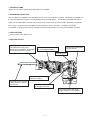
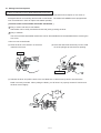
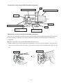
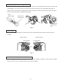
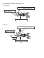
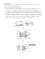
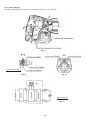
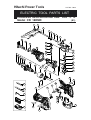
MODEL
CR 18DMR
Hitachi
Power Tools
C
CORDLESS
RECIPROCATING SAW
CR 18DMR
LIST No. G824
TECHNICAL DATA
AND
SERVICE MANUAL
June 2005
SPECIFICATIONS AND PARTS ARE SUBJECT TO CHANGE FOR IMPROVEMENT
REMARK:
Throughout this TECHNICAL DATA AND SERVICE MANUAL, a symbol(s)
is(are) used in the place of company name(s) and model name(s) of our
competitor(s). The symbol(s) utilized here is(are) as follows:
Competitors
Symbols Utilized
Company Name
Model Name
D
DEWALT
DC385
M
MAKITA
JR180DWD
R
RIDGID
R844
B
BOSCH
1644-24
W
MILWAUKEE
6514-20
CONTENTS
Page
1. PRODUCT NAME ................................................................................................................................ 1
2. MARKETING OBJECTIVE .................................................................................................................. 1
3. APPLICATIONS ................................................................................................................................... 1
4. SELLING POINTS ............................................................................................................................... 1
4-1. Selling Point Descriptions ..................................................................................................................... 2
5. SPECIFICATIONS ............................................................................................................................... 6
5-1. Specifications ........................................................................................................................................ 6
5-2. Optional Accessories ............................................................................................................................ 7
6. COMPARISONS WITH SIMILAR PRODUCTS ................................................................................... 9
6-1. Specification Comparisons (18 V cordless reciprocating saw) ............................................................. 9
6-2. Working Performance per Single Charge (reference only) ................................................................. 10
7. PRECAUTIONS IN SALES PROMOTION ........................................................................................ 12
7-1. Safety Instructions .............................................................................................................................. 12
7-2. Inherent Drawbacks of Cordless Reciprocating Saw Requiring Particular Attention
During Sales Promotion ...................................................................................................................... 14
7-3. Front Cover ......................................................................................................................................... 15
8. REPAIR GUIDE ................................................................................................................................ 15
8-1. Precautions in Disassembly and Reassembly .................................................................................... 15
9. STANDARD REPAIR TIME (UNIT) SCHEDULES ............................................................................ 21
Assembly Diagram for CR 18DMR
1. PRODUCT NAME
Hitachi 18 V Cordless Reciprocating Saw, Model CR 18DMR
2. MARKETING OBJECTIVE
The new Model CR 18DMR is the upgraded version of the current Model CR 18DV. The Model CR 18DMR is of
the popular DMR-series design and compatible with the new flat battery. The Model CR 18DMR features the
carbon brush-replaceable, powerful and long-life motor, Hitahci-original tool-less blade detachable mechanism
that is easy to maintain and comfortable soft grip handle for ease of operation. In addition, the Model
CR 18DMR is equipped with the high-strength components equivalent to the 24-V product Model CR 24DV.
3. APPLICATIONS
Cutting metal, wood, plastics, etc.
4. SELLING POINTS
Easy-to-operate/maintain tool-less
blade detachable mechanism
(The Model CR 18DMR is serviceable
without removing the front cover.)
Nonskid and comfortable
soft grip handle
Widely rubber-covered case
for comfortable handling
Lock-off button
Effective cooling to enable
continuous cutting
Saw blade can be mounted
in either direction, upward
or downward
Replaceable carbon brush
to elongate motor life
Convenient switch with large
trigger shape for easy operation
--- 1 ---
4-1. Selling Point Descriptions
(1) Easy-to-maintain tool-less blade detechable mechanism
Recently, most saber saws on the market are equipped with a mechanism that requires no tool such as
hexagonal wrench for mounting and removal of saw blades. The Model CR 18DMR is also equipped with
such a mechanism in order to replace saw blades speedily.
[ Features of the tool-less blade detachable mechanism ]
1 Easy to mount and remove saw blades
Saw blades can be easily mounted and removed just by pressing the lever.
2 Easy to maintain
The tool-less blade detachable mechanism can be disassembled and reassembled without removing the
front cover.
<How to mount a saw blade>
(a) Push the lever in the direction of the arrow
(b) Insert the saw blade all the way into the small
marked on the lever.
slit of the plunger tip with the lever pushing.
Lever
Saw blade
(c) Release the lever and pull the back of the saw blade two or three times by hand to check that the
blade is securely mounted. When pulling the blade, you will know it is properly mounted if it clicks and
the lever moves slightly.
Click
--- 2 ---
< Construction of the tool-less blade detachable mechanism >
Nut
Holder pin to secure the blade
Plunger (reciprocating shaft)
Saw blade
Spring
Spring to pull back the holder pin
Bolt
Heat- and dust-resistant
rubber cap
Lever to mount and
remove saw blades
< Maintenance of the tool-less blade detachable mechanism >
After use, clean the blade mount with a brush to ensure that the tool-less blade detachable mechanism can
function smoothly. In addition to the regular maintenance, perform the following effective maintenance
occasionally.
Cleaning the inside of the tool-less blade detachable mechanism
Pull the rubber cap provided on the lever in the direction of an arrow mark shown below. Then the rubber
cap can be removed from the lever easily. Remove dust from the inside of the blade holder with air or the
like.
Blade holder
Rubber cap
--- 3 ---
< Disassembly and cleaning of the tool-less blade detachable mechanism >
The tool-less blade detachable mechanism can be easily disassembled or reassembled because the fixing
bolt can be loosened or tightened without removing the front cover. To disassemble the tool-less blade
detachable mechanism, remove the fixing bolt and pull out the blade holder.
CAUTION: This is a special bolt comprised of an M4 thread and an M5 hexagonal socket. Be careful
not to break the bolt by overtightening.
Blade holder
Front cover
Fixing bolt
In case the saw blade is apt to come off
The saw blade is apt to come off if the blade hole is worn out. Replace the saw blade with new one. If the
new saw blade comes off even after replacement, the holder pin may be worn out. Replace the holder pin
with new one.
Blade hole
Refer to the Handling Instructions for detailed information about saw blade replacement.
(2) Saw blade can be mounted in either direction, upward or downward
The Model CR 18DMR is convenient for cutting materials on the floor or near window frames, and also for
plunge cutting on plywood panels because the saw blade can be installed upside down.
< Plunge cutting on plywood panels >
Fig. 1
Refer to the Handling Instructions for detailed information about plunge cutting on plywood panels.
--- 4 ---
(3) Replaceable carbon brush to elongate motor life
The carbon brush can be replaced from the outside of the motor to elongate the motor life and to enhance the
maintainability. The carbon brush can be easily removed from the motor with a flat-blade screwdriver as
shown in Fig. 2, and can also be easily and securely mounted to the motor by hooking the nail of the carbon
brush on the contact portion outside the brush tube.
Nail of
carbon brush
Protrusion of
carbon brush
Contact portion
outside brush
tube
Fig. 2
(4) Lock-off button
The lock-off button is adopted to avoid the switch from unintentionally being turned on during storage or
carrying.
< When locking >
< When using >
Lock-off button
Lock-off button
Push
Fig. 3
(5) Convenient switch trigger shape for easy operation
The switch trigger is large enough to operate with two fingers for ease of operation. Even if the tool is upside
down as shown in Fig. 1, the trigger switch can be easily operated.
--- 5 ---
5. SPECIFICATIONS
5-1. Specifications
Capacity
Max. cutting size
Number of stroke
0 --- 2,100/min.
Stroke
28 mm (1-1/8")
Type of motor
DC magnet motor
Enclosure
Housing
Front cover
Gear cover and upper cover
Storage battery
Charger
Steel pipe outer diameter
Wood thickness
Mild steel plate (thickness)
90 mm (3-1/2")
90 mm (3-1/2")
10 mm (3/8")
Max. output: 380 W
••••••••• • • • • • • • • • • • • • • • • • • • • • • • • • •
••••••••••••••••••••••••••••••
•••••
••••••••••••••••••••••••
•••••••••••••••••••••••••••••••••••
Glassfiber reinforced polycarbonate resin
TPE (Thermoplastic elastomer)
Aluminum alloy die casting
Glassfiber reinforced polyamide resin
ABS resin
Type of switch
Variable trigger switch (with brake)
Handle shape
D-type handle
Weight
Main body
3.8 kg (8.4 lbs.) (with battery)
Charger UC 24YFA 0.6 kg (1.3 lbs.)
Sealed cylinder nickel cadmium storage battery
Nominal voltage: DC 18V
Nominal life: Charging/discharging: approximately 1,000 times
(in case of Model UC 24YFA)
Nominal capacity: 2.0 Ah
Battery
(Model EB 1820L)
Battery
(Model EB 1826HL/EB 1830HL)
Sealed cylinder nickel-metal hydride storage battery
Nominal voltage: DC 18V
Nominal life: Charging/discharging: approximately 500 times
(in case of Model UC 24YFA)
Nominal capacity: 2.6 Ah/3.0 Ah
Charger
(Model UC 24YFA)
Overcharge protection system:
(1) Battery voltage detection ( 2V system) for Ni-Cd battery
Mi-MH battery temperature detection (dT/dt system) for Ni-MH battery
(2) Battery surface temperature detection (thermostat or thermistor)
(3) 120 minutes timer
Power input: 90 W
Charging time: Approx. 50 minutes [for type EB 1820L battery at 20ûC (68ûF)]
Approx. 60 minutes [for type EB 1826HL battery at 20ûC (68ûF)]
Approx. 70 minutes [for type EB 1830HL battery at 20ûC (68ûF)]
Operable ambient temperature range: 0ûC --- 40ûC (32ûF --- 104ûF)
The maximum allowable temperature of the type EB 1820L battery is 60ûC
(140ûF) and the type EB 1826HL or EB 1830HL battery is 45ûC (113ûF).
Indication method of battery charging function:
--- 6 ---
Standard accessories
(BLFK)
(HLFK)
Charger (UC 24YFA)
Battery (EB 1820L/EB 1830HL)
Blade (No. 103)
Hexagonal bar wrench
Plastic case
••••••••••••••••••••••••••••••••••••••••••••••••••••••••••••••••••••••••••••
•••••••••••••••••••••••••••••••••••••••••••••••••••••••••••••
• • • • • • • • • • • • • • • • • • • • • • • • • • • • • • • • • • • • • • • • • • • • • • • • • • • • • • • • • • • • • • • • • • • • • • • • • • • • • • • • • • • •
••••••••••••••••••••••••••••••••••••••••••••••••••••••••••••••••••••••••••
• • • • • • • • • • • • • • • • • • • • • • • • • • • • • • • • • • • • • • • • • • • • • • • • • • • • • • • • • • • • • • • • • • • • • • • • • • • • • • • • • • • • • • • • •
(2BLFK) Charger (UC 24YFA)
(2HLFK) Battery (EB 1820L/EB 1826HL/EB 1830HL)
Blade (No. 103)/Blade (No. 103, No. 132) (Only for USA)
Hexagonal bar wrench
Plastic case
••••••••••••••••••••••••••••••••••••••••••••••••••••••••••••••••••••••••••••
•••••••••••••••••••••••••••••••••••••••••••
••••••••••••••••••••••
••••••••••••••••••••••••••••••••••••••••••••••••••••••••••••••••••••••••••
• • • • • • • • • • • • • • • • • • • • • • • • • • • • • • • • • • • • • • • • • • • • • • • • • • • • • • • • • • • • • • • • • • • • • • • • • • • • • • • • • • • • • • • • •
1
1
1
1
1
1
2
1
1
1
5-2. Optional Accessories
The motor may lock depending on types of blades and materials used. For example, the motor may lock when
cutting a steel pipe 45 mm in outer diameter with the No. 132 BI-METAL blade. Customers must be instructed to
use appropriate blades corresponding to the materials to be cut.
(1) HCS blades
The blade numbers of HCS blades in Table 1 are engraved in the vicinity of the mounting position of each blade.
Select appropriate blades by referring to Tables 1 and 3 below.
Table 1: HCS blades
Blade No.
Uses
Thickness (mm)
No. 1
For cutting steel pipes less than 100 mm (4") in outer diameter
2.5 --- 6 (3/32" --- 1/4")
No. 2
For cutting steel pipes less than 30 mm (1-3/16") in outer diameter
2.5 --- 6 (3/32" --- 1/4")
No. 3
For cutting steel pipes less than 30 mm (1-3/16") in outer diameter
Below 3.5 (1/8")
No. 4
For cutting and roughing lumber
50 --- 70 (2" --- 2-3/4")
No. 5
For cutting and roughing lumber
Below 30 (1-3/16")
No. 8
For cutting vinyl chloride pipes less than 100 mm (4") in outer
diameter
2.5 --- 15
(3/32" --- 5/8")
For cutting and roughing lumber
Below 100 (4")
2.5 --- 6 (3/32" --- 1/4")
No. 9
For cutting steel pipes less than 100 mm (4") in outer diameter
No. 95
For cutting steel and stainless pipes less than 100 mm (4") in outer
diameter
Below 2.5 (3/32")
No. 96
For cutting steel and stainless pipes less than 30 mm (1-3/16") in
outer diameter
Below 2.5 (3/32")
--- 7 ---
(2) BI-METAL blades
The blade numbers of BI-METAL blades in Table 2 are engraved in the vicinity of the mounting position of each
blade. Select appropriate blades by referring to Table 2 and 3 below.
Table 2: BI-METAL blades
Blade No.
Uses
Thickness (mm)
No. 101
For cutting steel and stainless pipes less than 60 mm (2-3/8") in outer diameter 2.5 --- 6 (3/32" --- 1/4")
No. 102
For cutting steel and stainless pipes less than 100 mm (4") in outer diameter
No. 103
For cutting steel and stainless pipes less than 60 mm (2-3/8") in outer diameter 2.5 --- 6 (3/32" --- 1/4")
No. 104
For cutting steel and stainless pipes less than 100 mm (4") in outer diameter
No. 105
For cutting steel and stainless pipes less than 60 mm (2-3/8") in outer diameter 2.5 --- 6 (3/32" --- 1/4")
No. 106
For cutting steel and stainless pipes less than 100 mm (4") in outer diameter
No. 107
For cutting steel and stainless pipes less than 60 mm (2-3/8") in outer diameter
Below 3.5 (1/8")
No. 108
For cutting steel and stainless pipes less than 100 mm (4") in outer diameter
Below 3.5 (1/8")
No. 121
For cutting and roughing lumber
No. 131
All purpose
No. 132
All purpose (except for cutting steel and stainless pipes more than 30 mm
(1-3/16") in outer diameter)
2.5 --- 6 (3/32" --- 1/4")
2.5 --- 6 (3/32" --- 1/4")
2.5 --- 6 (3/32" --- 1/4")
100 (4")
(3) Selection of blades for other materials
Table 3
Material to be cut
Iron plate
Material quality
Mild steel plate
Thickness (mm)
2.5 --- 10 (3/32" --- 3/8")
Below 3.5 (1/8")
Nonferrous metal
Aluminum
Copper
Brass
Phenol resin
Melamine resin etc.
Synthetic resin
Vinyl chloride
Acrylic resin etc.
5 --- 10 (3/16" --- 3/8")
Below 5 (3/16")
Blade No.
No. 1, 2, 101, 102, 103, 104,
105, 106, 131, 132
No. 3, 6, 107, 108
No. 1, 2, 101, 102, 103, 104,
105, 106, 131, 132
No. 3, 6, 107, 108
10 --- 30 (3/8" --- 1-3/16")
No. 1, 2, 4, 101, 102, 103, 104,
131, 132
5 --- 20 (3/16" --- 3/4")
No. 3, 5, 8, 105, 106, 107, 108
10 --- 30 (3/8" --- 1-3/16")
No. 1, 2, 4, 101, 102, 103, 104,
131, 132
5 --- 20 (3/16" --- 3/4")
No. 3, 5, 8, 105, 106, 107, 108
--- 8 ---
--- 9 ---
6-1. Specification Comparisons (18 V cordless reciprocating saw)
6. COMPARISONS WITH SIMILAR PRODUCTS
6-2. Working Performance per Single Charge (reference only)
< Cutting steel pipes >
Steel pipe 40 A (outer diameter: 48.6 mm (1.91")
thickness: 3.5 mm (0.14"))
HITACHI genuine blade No. 103
for cutting steel pipes
Pressing force about 5 kgf (11 lbs.)
Fig. 4
< Cutting wood >
Lumber: SPF 2 x 10 (38 mm (1.50") in thickness and
235 mm (9.25") in width)
Width
HITACHI genuine blade
No. 121 for cutting wood
Thickness
Pressing force about 5 kgf (11 lbs.)
Fig. 5
--- 10 ---
--- 11 ---
R
W
B
M
R
W
B
M
such as the pressing force, type of blades, materials, etc.
The following test data should be used for reference purposes only since the cutting speed and the working capacity may vary depending on the operating conditions
7. PRECAUTIONS IN SALES PROMOTION
7-1. Safety Instructions
In the interest of promoting the safest and most efficient use of the Model CR 18DMR by all our customers, it is
very important that at the time of sale, the salesperson carefully ensures that the buyer seriously recognizes the
importance of the contents of the Handling Instructions, and fully understands the meaning of the precautions
listed on the Caution Plate and Name Plate attached to each tool.
A. Handling Instructions
Salespersons must be thoroughly familiar with the contents of the Handling Instructions in order to give pertinent
advice to the customer. In particular, they must have a thorough understanding of the precautions in the use of
the cordless (battery charger type) electric power tools which are different from those of ordinary electric power
tools.
(1) Before use, ensure that the unit is fully charged.
New units are not fully charged. Even if the units were fully charged at the factory, long periods without use,
such as during shipping, cause the storage battery to lose its charge. Customers must be instructed to fully
charge the unit prior to use.
(2) When charging storage batteries, use only the exclusive Model UC 24YFA Charger provided with the tool.
Because of the designed rapid-charging feature (about one hour), use of other battery chargers is hazardous.
(3) Ensure the power source voltage is the same as that indicated on the Name Plate of the charger. Use of any
other power source (DC outlet, fuel powered generator, etc.) will cause the charger to overheat and burnt out.
(4) Do not use any voltage increasing equipment (transformer etc.) between the power source and the charger.
If the charger is used with voltage over and above that indicated on the unit, it will not function properly.
(5) Conduct battery charging at an ambient temperature range of 0 ûC --- 40 ûC (32 ûF --- 104 ûF).
Special temperature sensitive devices are employed in the charger to permit rapid charging. Ensure that
customers are instructed to use the charger at the indicated ambient temperature range. At temperature over
40 ûC (104 ûF), the storage battery cannot be sufficiently charged. The optimum temperature range is 20 ûC --25 ûC (68 ûF --- 77 ûF).
(6) The battery charger should not be used continuously.
At high ambient temperature, if over three storage batteries are charged in succession, the temperature of the
coils on the transformer will rise. After charging one battery, please charge the next battery after about a
fifteen-minute inerval.
(7) Do not insert foreign objects into the air vents on the charger
The charger case is equipped with air vents to protect the internal electronic components from overheating.
Caution the customer not to allow foreign materials, such as metallic or inflammable objects, to be dropped or
inserted into the air vents. This could cause electrical shock, fire, or other serious hazards.
(8) Do not attempt to disassemble the storage battery or the charger.
Special devices, such as a thermistor, are built into the storage battery and charger to permit rapid charging.
Incorrect parts replacement and/or wiring will cause malfunctions which could result in fire or other hazards.
Instruct the customer to bring these units to an authorized service center in the event repair or replacement is
necessary.
--- 12 ---
(9) Disposal of the Model EB 1820L, EB 1826HL or EB 1830HL storage battery
Ensure that all customers understand that Model EB 1820L, EB 1826HL or EB 1830HL Storage Battery should
be returned to the Hitachi power tool sales outlet or authorized service center when they are no longer capable
of being recharged or repaired. If thrown into a fire, the batteries may explode, or if discarded indiscriminately,
leakage of the cadmium compound contained in the battery may cause environmental pollution.
B. Caution Plate
(1) The following basic safety precautions are listed on the Name Plate attached to the main body of each tool.
For Australia and New Zealand
CAUTION
Read thoroughly HANDLING INSTRUCTIONS before use.
For the U.S.A. and Canada
WARNING
To reduce the risk of injury, user must read and understand
instruction manual.
AVERTISSEMENT
Afin de reduire le risque de blessures, I'utilisateur doit lire et
bien comprendre le mode d'emploi.
(2) The following cautions are listed on the Name Plate attached to the Model EB 1820L, EB 1826HL and
EB 1830HL batteries.
For Europe
CAUTION
For the U.S.A. and Canada
Read thoroughly
CAUTION
For safe operation, see
HANDLING INSTRUCTIONS before
instruction manual.
use.
charger UC 24YFA for recharging.
Do not disassemble nor
Use HITACHI
throw into fire.
(3) The following caution is listed on the Name Plate attached to the Model UC 24YFA Charger.
For the U.S.A.
For safe operation, see Instruction Manual.
Charge HITACHI rechargeable battery types EB7, EB9, EB12, EB14, EB18
series, and EB24B. Other types of batteries may burst causing personal injury
and damage.
Charge between 32û and 104ûF.
Indoor use only.
Replace defective cord immediately.
--- 13 ---
7-2. Inherent Drawbacks of Cordless Reciprocating Saw Requiring Particular Attention During Sales Promotion
The cordless reciprocating saw offers many advantages; it can be used in places where no power source is
available, the absence of a cord allows easy use, etc. However, any cordless tool has certain inherent
drawbacks. Salespersons must be thoroughly familiar with these drawbacks in order to properly advise the
customer in the most efficient use of the tool.
A. Suggestions and precautions for the efficient use of the tool
(1) Do not insert a foreign object into body vent holes.
The body of this tool has vent holes for improving the cooling efficiency. As a fan is built into the motor, a
foreign object inserted through a vent hole may cause a failure. Please instruct customers to never insert a
foreign object into the vent hole.
(2) Avoid "Locking" of the motor.
Locking of the motor will cause an overload current that could result in burning of the motor and/or rapid
deterioration of the battery. Salespersons should advise the customer to immediately release the switch and
stop operation if the motor becomes locked.
(3) Variation in amount of work possible per charge
Although the nominal chargeable capacity of the storage batteries used with the Model CR 18DMR is 2.0 Ah,
2.6 Ah and 3.0 Ah, the actual capacity may vary within 10% of that value depending on the ambient
temperature during use and charging, and the number of times the batteries have been recharged. It should
be noted that other factors which may have a bearing on the amount of work possible per charge are the
working conditions (ambient temperature, type and moisture content of the workpiece, sharpness of the saw
blades, etc.) and operational skill of the user.
B. Suggestions and precautions for the efficient use of the charger and storage batteries
If the Model EB 1820L Storage Battery is exposed to direct sunlight for an extended period or if the tool has just
been operated for a long time, charging may not be possible if the temperature of the battery is above 60 ûC
(140 ûF). If the Model EB 1826HL/EB 1830HL Storage Battery is exposed to direct sunlight for an extended
period or if the tool has just been operated for a long time, charging may not be possible if the temperature of the
battery is above 45 ûF (113 ûF). In such a case, the customer should be advised to place the battery in a shaded
area with a good airflow, and allows sufficient cooling before recharging. This phenomenon is common to all
existing batteries and chargers which employ temperature sensitive overcharge protection devices. The cooling
time required before recharging can be accomplished varies from a few minutes to about 30 minutes, depending
on the load, duration of use, and ambient temperature.
--- 14 ---
7-3. Front Cover
WARNING:
The Model CR 18DMR is equipped with the front cover to protect the operator against possible electric
shock, and it is not intended for cutting live lines. The front cover covers both the gear cover and the
upper cover to protect the operator against electric shock in the event that a live line is accidentally cut
and electricity flows from the blade to the metallic enclosure. Customers must be instructed to hold the
handle (made of polycarbonate resin) with one hand and the other hand on the front cover to support the
main body during the cutting operation. Be sure to instruct the customers that the front cover must not
be removed when using the Model CR 18DMR.
8. REPAIR GUIDE
8-1. Precautions in Disassembly and Reassembly
Please follow the precautions below for disassembly and reassembly procedures. The circled numbers in the
following figures and the [Bold] numbers in the descriptions below correspond to the item numbers in the Parts
List. Prior to attempting disassembly or replacement of the saw blade, ensure that the battery is removed.
8-1-1. Disassembly
(1) Removal of the Upper Cover [8]
Remove the Saber Saw Blade [501]. Remove the Hex. Socket Hd. Bolt (W/Flange) M5 x 12 [25] and pull out
the Base [16]. Remove the two Machine Screws (W/Sp. Washer) M4 x 12 [17] and the Cover Plate [18], and
pull out the Front Cover [19]. Remove the four Hex. Socket Hd. Bolts (W/Sp. Washer) M5 x 16 [9] from the
Upper Cover [8]. Pull the Upper Cover [8] straight and remove it.
(2) Removal of the Plunger [3] from the Upper Cover [8]
Remove the two Seal Lock Hex. Socket Flat Hd. Bolts M5 x 12 [28] from the Connector [33]. If the Seal Lock
Hex. Socket Flat Hd. Bolts M5 x 12 [28] are too tight, heat the Upper Cover [8] to 100 --- 150ûC then loosen the
Seal Lock Hex. Socket Flat Hd. Bolts M5 x 12 [28]. Pull the Plunger [3] forward (toward the blade) and
remove from the Upper Cover [8].
(3) Removal of the Gear Cover Ass'y [27] and the Housing (A).(B) Set [46]
Remove the two Brush Caps [47] and the two Carbon Brushes (1 Pair) [48]. Remove the four Tapping Screws
(W/Sp. Washer) D5 x 30 [26]. Then the Gear Cover Ass'y [27] (together with the Armature Ass'y DC 18V [41])
and Housing (A).(B) Set [46] can be removed.
(4) Removal of the Gear Cover Ass'y [27] from the Armature Ass'y DC 18V [41]
Remove the three Machine Screws (W/Sp. Washer) M4 x 12 [17]. Then the Gear Cover Ass'y [27] can be
removed from the Armature Ass'y DC 18V [41].
(5) Disassembly of the Armature Ass'y DC 18V [41]
Remove the Retaining Ring (E-type) for D10 Shaft [38] from the Armature Ass'y DC 18V [41] with a flat-blade
screwdriver. Remove the Ball Bearing 6001VVCMPS2L [39] from the pinion side with the bearing puller ass'y
(J-30). Then Bearing Cover (A) [40] can be removed. Remove the Ball Bearing 608VVC2PS2L [42] from the
commutator side with the bearing puller ass'y (J-30).
--- 15 ---
(6) Removal of the Gear [37] from the Gear Cover Ass'y [27]
Remove the three Seal Lock Flat Hd. Screws M4 x 12 [20] through the hole of the Balance Weight [36].
Then the Gear [37] (together with the Balance Weight [36], Spindle [23] and others) can be removed from the
Gear Cover Ass'y [27].
(7) Removal of the Gear [37] from the Spindle [23]
Hold at the width-across-flat portions of the Spindle [23] with a vise and remove the Nylock Hex. Socket Flat
Hd. Bolt M6 x 16 [29]. Remove the Balance Weight [36], Gear [37], Bearing Cover (B) [21] and Ball Bearing
6901ZZCMPS2L [22].
(8) Disassembly of the blade mounting section
Slide the Cap [11] (made of rubber) out of Lever (A) [12] with fingers horizontally. Remove the Special Bolt
M4 [10]. Then Blade Holder (A) [1], Lever (A) [12], Spring (D) [13], Holder Pin (B) [14] and Spring (B) [15]
can be removed from the Plunger [3]. At this time, be careful not to lose Spring (B) [15].
[2]
[1]
[3]
[15]
[14]
[13]
[12]
[11]
[10]
Fig. 6
(9) Disassembly of the housing section
Remove the seven Tapping Screws (W/Flange) D4 x 20 (Black) [55] and Housing (A).(B) Set [46]. Then the
Pushing Button [52] and the power supply ass'y (DC-Speed Control Switch [53], Brush Block [44], Magnet
[43] and Terminal Piece [51] are mounted) can be removed.
[43]
[44]
[45]
[54]
[55]
[53]
[52]
[48]
[46] [47]
[51]
[57]
[56]
[49]
[50]
Fig. 7
--- 16 ---
8-1-2. Reassembly
Reassembly can be accomplished by following the disassembly procedures in reverse. However, special
attention should be given to the following items.
(1) Mounting the saw blade mount (Figs. 8, 9 and 10)
Insert Spring (B) [15] and Holder Pin (B) [14] into the Plunger [3]. Apply Shell ALVANIA RL3 grease to the
slanted portion of Lever (A) [12]. Mount the shorter end of Spring (D) [13] into Lever (A) [12] then mount
Lever (A) [12] into Blade Holder (A) [1]. Keeping this state, insert the tip of Plunger [3] into Blade Holder (A)
[1]. At this time, fit Spring (D) [13] in the groove of the Plunger [3] securely. Tighten the Special Bolt M4 [10]
and Nut M4 (Black) [2] at the specified torque. Push the Cap [11] to Lever (A) [12] from the side so that the
arrow mark on the Cap [11] points downward. At this time, check that there is no gap between the Cap [11]
and Blade Holder (A) [1]. Be careful not to break the Special Bolt M4 [10] by overtightening with an M5
hexagonal wrench. Finally, mount and dismount the saw blade to check for operation.
[3]
[1]
[12]
[14]
[13]
[15]
Fig. 8
[2]
[3]
[15]
[1]
[14]
[13]
[12]
[10]
[11]
Fig. 9
[11]
[10] [13] [3]
Fig. 10
--- 17 ---
Groove of plunger
(2) Reinstallation of the spindle and gear section to the Gear Cover Ass'y [27]
Insert the Spindle [23] into the Ball Bearing 6901ZZCMPS2L [22], Bearing Cover (B) [21], Gear [37] and
Balance Weight [36] in order. Secure the spindle and gear section secured with the Nylock Hex. Socket Flat
Hd. Bolt M6 x 16 [29] to the Gear Cover Ass'y [27] with the three Seal Lock Flat Hd. Screws M4 x 12 [20]
aligning the holes of the Balance Weight [36] with the holes of Bearing Cover (B) [21] and the screw holes of
the Gear Cover Ass'y [27]. If the first Seal Lock Flat Hd. Screw M4 x 12 [20] is tightened firmly, the other two
Seal Lock Flat Hd. Screws M4 x 12 [20] cannot be aligned. Lightly tighten the first Seal Lock Flat Hd. Screw
M4 x 12 [20].
(3) Mount the Felt Packing [5], Packing Washer [4] and O-ring (1AP-12) [6] without fail before inserting the
Plunger [3] into the Upper Cover [8].
(4) Mount the Seal Packing [30] and Packing (B) [31] without fail when mounting the Upper Cover [8] to the Gear
Cover Ass'y [27].
(5) Align the notch of the Magnet [43] with the protrusion of housing (A) side of Housing (A).(B) Set [46] when
mounting the Magnet [43] to Housing (A).(B) Set [46].
(6) Do not pinch internal wires between the matching surfaces of Housing (A).(B) Set [46] when storing internal
wires in Housing (A). (B) Set [46].
(7) Adhesives are applied to the following screws and bolts. When reusing these screws and bolts, apply
Cemedine 1500 or Three Bond TB2410 to them.
Nylock Hex. Socket Flat Hd. Bolt M6 x 16 [29] ................................................. Cemedine 1500
Seal Lock Hex. Socket Flat Hd. Bolt M5 x 12 [28] ............................................ Cemedine 1500
Seal Lock Flat Hd. Screw M4 x 12 [20] ............................................................. Three Bond TB2410
(8) A total of 35 g Shell ALVANIA RL3 grease is applied in the Gear Cover Ass'y [27] and the Upper Cover [8].
Apply grease sufficiently to the following portions:
Needle Roller [35] in the Gear Cover Ass'y [27]
Connecting Piece (A) [34]
Tooth space and D7 pin of the Gear [37]
Inside of the Connector [33]
Sliding surface between the Connector [33] and the Upper Cover [8]
Sliding surface between the Metal [7] and the Plunger [3]
Inside of the Gear Cover Ass'y [27]
Sliding surface of the Spindle [23]
--- 18 ---
(9) Tightening torques
Tapping Screw (W/Flange) D4 x 20 (Black) [55] ............................................. 2.0
0.5 N•m (20
5 kgf•cm)
Tapping Screw (W/Sp. Washer) D5 x 30 [26] .................................................. 2.9
0.5 N•m (30
5 kgf•cm)
Machine Screw (W/Washers) M3 x 12 [57] ..................................................... 0.5 to 0.8 N•m (5 to 8 kgf•cm)
Machine Screws (W/Sp. Washer) M4 x 12 [17] .............................................. 1.8
0.4 N•m (18
4 kgf•cm)
Seal Lock Flat Hd. Screw M4 x 12 [20] ........................................................... 1.8
0.4 N•m (18
4 kgf•cm)
Hex. Socket Hd. Bolt (W/Sp. Washer) M5 x 16 [9] .......................................... 8.8
1.0 N•m (90
10 kgf•cm)
Seal Lock Hex. Socket Flat Hd. Bolt M5 x 12 [28] .......................................... 5.4
0.5 N•m (55
5 kgf•cm)
Nylock Hex. Socket Flat Hd. Bolt M6 x 16 [29] ............................................... 11.8
1.0 N•m (120
Nut M4 [2] ........................................................................................................ 2.9
0.5 N•m (30
--- 19 ---
10 kgf•cm)
5 kgf•cm)
8-1-3. Wiring diagram
Be sure to perform wiring connections as indicated in Figs. 12, 13, 14 and 15.
Fig. 11
Internal wire (Red)
Fig. 12
Fig. 13
Wiring diagram
Fig. 14
--- 20 ---
9. STANDARD REPAIR TIME (UNIT) SCHEDULES
MODEL
Variable
Fixed
10
20
30
Work Flow
CR 18DMR
DC-Speed
Control Switch
Terminal Piece
Set
Housing
(A). (B) Set
Magnet
Armature Ass'y
Ball Bearing
(608VV)
Ball Bearing
(6001VV)
General Assembly
Base
Front Cover
Gear Cover
Ass'y
Spindle
Ball Bearing
(6901ZZ)
Gear
Needle Roller
Connecting
Piece (A)
Connector
Connector
Holder
Blade Holder (A)
Plunger
O-ring
Upper Cover
Seal Packing
--- 21 ---
40
50
60
Hitachi Power Tools
LIST NO. G824
ELECTRIC TOOL PARTS LIST
CORDLESS RECIPROCATING SAW
Model CR 18DMR
2005
•
4 • 15
(E1)
2
1
3
10
12
11
13
14
15
4
5
6
7
8
16
9
17
20
18
7
21
19
22
30
23
31
24
38
32
39
40
33
17
28
34
41
29
35
25
42
43
26
36
44
37
27
45
54
55
53
501
48
52
47
51
46
502
503
57
504
56
58
505
49
50
PARTS
ITEM
NO.
1
*
CR 18DMR
CODE NO.
NO.
USED
DESCRIPTION
321-132
BLADE HOLDER (A)
1
2
322-709
NUT M4 (BLACK)
1
3
324-472
PLUNGER
1
4
996-401
PACKING WASHER
1
5
996-400
FELT PACKING
1
6
996-407
O-RING (1AP-12)
1
7
956-589
METAL
2
8
324-471
UPPER COVER
1
9
305-574
HEX. SOCKET HD. BOLT (W/SP. WASHER) M5X16
4
10
322-134
SPECIAL BOLT M4
1
11
321-130
CAP
1
12
321-131
LEVER (A)
1
13
321-135
SPRING (D)
1
14
321-134
HOLDER PIN (B)
1
15
318-483
SPRING (B)
1
16
319-866
BASE
1
17
951-039
MACHINE SCREW (W/SP. WASHER) M4X12
5
18
324-474
COVER PLATE
1
19
324-473
FRONT COVER
1
20
993-244
SEAL LOCK FLAT HD. SCREW M4X12
3
21
319-849
BEARING COVER (B)
1
22
690-1ZZ
BALL BEARING 6901ZZCMPS2L
1
23
319-848
SPINDLE
1
24
954-789
METAL (B)
1
25
996-399
HEX. SOCKET HD. BOLT (W/FLANGE) M5X12
1
26
986-011
TAPPING SCREW (W/SP. WASHER) D5X30
4
27
319-844
GEAR COVER ASS’Y
1 INCLUD. 24
28
319-875
SEAL LOCK HEX. SOCKET FLAT HD. BOLT M5X12
2
29
319-851
NYLOCK HEX. SOCKET FLAT HD. BOLT M6X16
1
30
319-856
SEAL PACKING
1
31
319-874
PACKING (B)
1
32
983-567
CONNECTOR HOLDER
1
REMARKS
33
996-405
CONNECTOR
1
34
983-541
CONNECTING PIECE (A)
1
35
324-470
NEEDLE ROLLER
1
36
319-852
BALANCE WEIGHT
1
37
324-469
GEAR
1
38
670-514
RETAINING RING (E-TYPE) FOR D10 SHAFT
1
39
600-1VV
BALL BEARING 6001VVCMPS2L
1
40
319-843
BEARING COVER (A)
1
41
360-703
ARMATURE ASS’Y DC 18V
1 INCLUD. 38-40, 42
42
608-VVM
BALL BEARING 608VVC2PS2L
1
43
324-468
MAGNET
1
44
324-478
BRUSH BLOCK
1
45
318-247
FERRITE CORE
1 EXCEPT FOR AUS, NZL, USA, CAN, CHN
46
324-475
HOUSING (A). (B) SET
1
47
319-847
BRUSH CAP
2
48
999-058
CARBON BRUSH (1 PAIR)
2
HITACHI LABEL
1
CAUTION LABEL
1
TERMINAL PIECE
1
49
50
51
--- 2 ---
324-517
* ALTERNATIVE PARTS
4 -- 05
PARTS
ITEM
NO.
52
53
CR 18DMR
CODE NO.
NO.
USED
DESCRIPTION
319-760
PUSHING BUTTON
1
319-861
DC-SPEED CONTROL SWITCH
1
NAME PLATE
1
54
55
302-086
TAPPING SCREW (W/FLANGE) D4X20 (BLACK)
8
56
319-812
HEAT SINK
1
57
993-963
MACHINE SCREW (W/WASHERS) M3X12
1
*
58
322-880
BATTERY EB 1820L (W/ENGLISH N.P.)
2
*
58
322-878
BATTERY EB 1826HL (W/ENGLISH N.P.)
2
*
58
322-877
BATTERY EB 1830HL (W/ENGLISH N.P.)
2
*
58
322-876
BATTERY EB 1830HL (W/ENGLISH N.P.)
2 FOR TPE
4 -- 05
* ALTERNATIVE PARTS
REMARKS
--- 3 ---
CR 18DMR
STANDARD ACCESSORIES
ITEM
NO.
501
*
502
CODE NO.
DESCRIPTION
NO.
USED
318-613
SABER SAW BLADES NO. 103 150L P. 14 (5 PCS.)
1
318-621
SABER SAW BLADES NO. 132 203L (5 PCS.)
1 FOR USA
503
944-458
HEX. BAR WRENCH 4MM
1
504
324-313
CASE
1
CHARGER (MODEL UC 24YFA)
1
505
REMARKS
OPTIONAL ACCESSORIES
ITEM
NO.
601
CODE NO.
NO.
USED
DESCRIPTION
959-610
SABER SAW BLADES NO. 1 (5 PCS.)
1
602
958-182
SABER SAW BLADES NO. 2 (5 PCS.)
1
603
958-183
SABER SAW BLADES NO. 3 (5 PCS.)
1
604
959-611
SABER SAW BLADES NO. 4 (5 PCS.)
1
605
958-185
SABER SAW BLADES NO. 5 (5 PCS.)
1
606
958-188
SABER SAW BLADES NO. 8 (5 PCS.)
1
607
996-427
SABER SAW BLADES NO. 9 (3 PCS.)
1
608
959-799
SABER SAW BLADES NO. 95 (3 PCS.)
1
609
959-800
SABER SAW BLADES NO. 96 (3 PCS.)
1
610
318-611
SABER SAW BLADES NO. 101 150L P. 10 (5 PCS.)
1
611
318-612
SABER SAW BLADES NO. 102 228L P. 10 (5 PCS.)
1
612
318-614
SABER SAW BLADES NO. 104 228L P. 14 (5 PCS.)
1
613
318-615
SABER SAW BLADES NO. 105 150L P. 18 (5 PCS.)
1
614
318-616
SABER SAW BLADES NO. 106 228L P. 18 (5 PCS.)
1
615
318-617
SABER SAW BLADES NO. 107 150L P. 24 (5 PCS.)
1
616
318-618
SABER SAW BLADES NO. 108 228L P. 24 (5 PCS.)
1
617
318-619
SABER SAW BLADES NO. 121 305L P. 6 (5 PCS.)
1
618
318-620
SABER SAW BLADES NO. 131 305L P. 10/14 (5PCS.)
1
619
318-621
SABER SAW BLADES NO. 132 203L (5 PCS.)
1
--- 4 ---
* ALTERNATIVE PARTS
REMARKS
Printed in Japan
(050415N)
4 -- 05