1
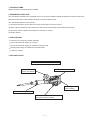
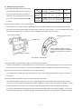
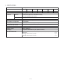
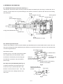
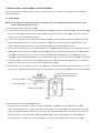
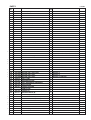
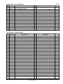
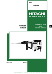
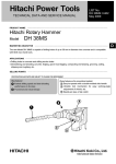
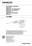
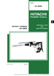
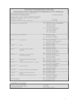
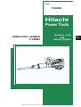
MODEL
H 65SB2
Hitachi
Power Tools
DEMOLITION HAMMER
H 65SB2
LIST No. E482
TECHNICAL DATA
AND
SERVICE MANUAL
Oct. 2004
SPECIFICATIONS AND PARTS ARE SUBJECT TO CHANGE FOR IMPROVEMENT
H
REMARK:
Throughout this TECHNICAL DATA AND SERVICE MANUAL, a symbol is
used in the place of company name and model name of our competitor.
The symbol utilized here is as follows:
Competitor
Symbol Utilized
Company Name
Model Name
C-1
MAKITA
HM1304
C-2
MAKITA
HM1500
CONTENTS
Page
1. PRODUCT NAME ........................................................................................................................... 1
2. MARKETING OBJECTIVE ............................................................................................................. 1
3. APPLICATIONS .............................................................................................................................. 1
4. SELLING POINTS .......................................................................................................................... 1
4-1. Selling Point Descriptions ............................................................................................................... 2
5. SPECIFICATIONS .......................................................................................................................... 3
5-1. Optional Accessories ...................................................................................................................... 4
6. COMPARISON WITH SIMILAR PRODUCTS ................................................................................ 5
6-1. Specification Comparison ............................................................................................................... 5
6-2. Demolition Performance Comparison ............................................................................................. 5
7. PRECAUTIONS IN SALES PROMOTION ..................................................................................... 6
7-1. Handling Instructions ...................................................................................................................... 6
7-2. Caution Plate .................................................................................................................................. 6
7-3. Grease Replacement ...................................................................................................................... 7
7-4. O-ring Replacement ........................................................................................................................ 7
8. REFERENCE INFORMATION ........................................................................................................ 8
8-1. Sealed and Dust-proof Structure .................................................................................................... 8
8-2. Vibration-proof Structure ................................................................................................................. 8
8-3. Stop Lever [Tool Retainer] .............................................................................................................. 8
8-4. Movement of Stop Lever ................................................................................................................. 9
9. PRECAUTIONS IN DISASSEMBLY AND REASSEMBLY .......................................................... 10
9-1. Disassembly ................................................................................................................................. 10
9-2. Reassembly .................................................................................................................................. 12
9-3. Application of Adhesive ................................................................................................................. 14
9-4. Tightening Torque ......................................................................................................................... 14
9-5. Wiring Diagram ............................................................................................................................. 15
9-6. Insulation Tests ............................................................................................................................. 15
9-7. No-load Current Value .................................................................................................................. 15
10. STANDARD REPAIR TIME (UNIT) SCHEDULES ..................................................................... 16
Assembly Diagram for H 65SB2
1. PRODUCT NAME
Hitachi Demolition Hammer, Model H 65SB2
2. MARKETING OBJECTIVE
The new Model H 65SB2 is the upgraded version of the current Model H 65SB, developed to realize the class-top
demolition performance and durability with low noise and vibration level.
The outstanding features are as follows:
(1) Strongest demolition power and lowest noise and vibration level in this class.
(2) More rigid and durable housing than that of the current model thanks to the analysis technology.
(3) Soft-touch switch handle comfortably fits in the palm of a hand.
(4) Unique design.
3. APPLICATIONS
Crushing of concrete and similar materials
Groove and channel digging in concrete
Groove and channel digging in asphalt and gravel roads
Tamping/compacting of asphalt and graveled roads
Cutting of asphalt
4. SELLING POINTS
Strongest demolition power in this class
Vibration absorbing handle
Soft-touch and 360û
rotation side-handle
Soft-touch grip for
easier handling
Vibration insulating structure
Internal double-insulation construction
with sturdy aluminum frame
--- 1 ---
4-1. Selling Point Descriptions
(1) Strongest demolition power in this class:
HITACHI
The powerful impact force of each blow
ensures efficient and easy crushing of
concrete. The crushing performance is 1.3
to 1.5 times more powerful than similar
products.
Concrete
demolition
ratio (%)
Concrete
demolition
amount (kg)
H 65SB2
HITACHI
H 65SB
C-1
C-2
100
89
67
80
192
256
230
287
(565.1 lbs.) (565.1 lbs.) (423.3 lbs.) (507.1 lbs.)
(2) Anti-vibration handle for less operator fatigue:
There are two anti-vibration rubbers, illustrated below, designed to efficiently absorb the vibration from the
main body of the tool, and minimize its transmission to the arms of the operator. One is mounted between the
handle and the gear cover; the other is mounted between the handle and the housing.
Anti-vibration rubber
Made of natural rubber
Handle side
The side handle made of natural
rubber reduces vibration transmitted
to hands for reduction of operator's
fatigue.
Anti-vibration rubber
Anti-vibration side handle
(3) Provided with shock absorbers to reduce vibration during operation.
Vibration transmitted from an attachment tool to the main body is reduced by floating the front cover with two
shock absorbers (front dampers). The Model H 65SB2 is easier to operate and reduces operator fatigue.
(4) Soft-touch switch handle comfortably fits in the palm of a hand.
The double-layer molded switch handle consists of a nylon resin base covered with a soft resin to ensure a
soft touch.
(5) Internal double-insulation construction with sturdy aluminum frame
The Model H 65SB2 is equipped with a very sturdy (highly rigid) aluminum die-cast outer frame that is the
same as the current Models H 65SB and H 45MR. In addition, a plastic internal S holder is adopted to realize
double-insulation construction. The housing has greater rigidity thanks to the ribs efficiently positioned
according to the analysis technology, and also the double-insulated motor has greater durability. The service
life of the carbon brushes is greatly prolonged, minimizing disconnection of the armature and grease leakage.
--- 2 ---
5. SPECIFICATIONS
Power source
AC single phase
Voltage
110 V
115 V
120 V
127 V
220 V
230 V
240 V
Current
12.8 A
12.2 A
11.8 A
11.2 A
6.4 A
6.1 A
5.9 A
AC single phase commutator motor
Type of motor
Enclosure
Material
Aluminum alloy die cast, cast aluminum alloy,
nylon resin (handle, back cover)
Painting
Silver green metallic and black
Type of switch
Trigger switch with stopper
Switch handle configuration
D-type handle
Power input
1,340 W (For Australia only 1,400 W)
Full-load blow per minute
1,400 BPM
Net weight
16.5 kg (36.4 lbs.) [Excluding cord]
Shipping weight
28.5 kg (62.8 lbs.)
Packaging
Corrugated cardboard box (with plastic tool case)
Standard accessories
Steel carrying case
Bull point
Hexagon bar wrench (for M8)
Hexagon bar wrench (for M4)
••••••••••••••••••••••••••••••••••••••••••••••••••••••••••••••••••••••••
• • • • • • • • • • • • • • • • • • • • • • • • • • • • • • • • • • • • • • • • • • • • • • • • • • • • • • • • • • • • • • • • • • • • • • • • • • • • • • • • • •• • • •
--- 3 ---
• • • • • • • • • • • • • • • • • • • • • • • • • • • • • • • • • • • • • • • • • • • • • • • • • • • • • • • • •
• • • • • • • • • • • • • • • • • • • • • • • • • • • • • • • • • • • • • • • • • • • • • • • • • • • • • • • • •
1 pc.
1 pc.
1 pc.
1 pc.
5-1. Optional Accessories
1
Grooving and edging work:
+
(1) Cold chisel
Overall length 410 mm
2
Part No. 944962
Digging work (Substitute for pickaxe):
+
(1) Scoop
Overall length 550 mm
3
Part No. 944967
Cutting and stripping work:
(Asphalt cutting and similar works)
+
(1) Cutter
Overall length 410 mm
4
Part No. 944964
Tamping work:
+
(1) Rammer
Ext. dia.: 200 mm
Part No. 944965
+
(2) Shank
Overall length 250 mm
Part No. 944966
Impact drill grease:
500 g (Can)
30 g (Tube)
Grease A
Part No. 980927
Part No. 981840
--- 4 ---
6. COMPARISON WITH SIMILAR PRODUCT
6-1. Specification Comparison
HITACHI
Maker
C-1
C-2
1,240
1,430
1,430
1,400
1,400
1,450
1,300
mm
726
726
647
647
Height
mm
246
235
217
215
Width
mm
118
120
116
117
J
42.0
42.0
27.5
28.5
H 65SB2
H 65SB
W
1,340
/min.
Length
Model
Power input
Full-load impact rate
Dimensions
Impact energy per stroke
Insulation structure
Double insulation Double insulation
Double insulation Double insulation
No-load noise level
dB (A)
84.6
85.1
85.2
Full-load vibration level
dB (VL)
121.5
123.0
124.0
Provided
Provided
Not provided
Not provided
16.5 (36.4 lbs.)
16.0 (35.3 lbs.)
15.0 (33.1 lbs.)
17.0 (37.5 lbs.)
Shock absorbing handle
Weight (without cord)
kg
Length
Height
dth
Wi
6-2. Demolition Performance Comparison
The products listed below were subjected to 30 minutes of chiseling operation on identical concrete structures or
blocks, and the amount of concrete demolished were compared as shown.
Demolished weight
for 30 min. (kg)
0
100
Demolished amount
(kg/30 min.)
300
200
H 65SB2
H 65SB
At rated
voltage
C-1
256
192
C-2
230
NOTE: The values above are for reference only. Demolition amount may vary in accordance with
operating conditions, operator skill, etc.
--- 5 ---
287
7. PRECAUTIONS IN SALES PROMOTION
In the interest of promoting the safest and most efficient use of the Model H 65SB2 Demolition Hammer by all of
our customers, it is very important that at the time of sale the salesperson carefully ensures that the buyer
seriously recognizes the importance of the contents of the Handling Instructions, and fully understands the
meaning of the precautions listed on the caution plate attached to each tool.
7-1. Handling Instructions
Although every effort is made in each step of design, manufacture, and inspection to provide protection against
safety hazards, the dangers inherent in the use of any electric tool cannot be completely eliminated. Accordingly,
general precautions and suggestions for the use of electric power tools, and specific precautions and suggestions
for the use of the Hammer are listed in the Handling Instructions to enhance the safe, efficient use of the tool by
the customer. Salespersons must be thoroughly familiar with the contents of the Handling Instructions to be able
to offer appropriate guidance to the customer during sales promotion.
7-2. Caution Plate
Each Model H 65SB2 is provided with a Caution Plate which lists basic precautions (illustrated below) in its use.
Carefully ensure that the customer fully understands and follows these precautions before using the tool.
CAUTION
Read thoroughly HANDLING INSTRUCTIONS before use.
Caution Plate on the back of the tool case lid
CAUTION
The grease should be exchanged once every six months
after the machine is purchased. The authorized HITACHI
power tool repair shop or the shop from where the tool
was bought should be instructed when it is time to
exchange the grease.
Before working on walls, floors, etc., check for buried or
hidden electrical wires and water or gas pipes.
--- 6 ---
7-3. Grease Replacement
Different kinds of grease are used in the electro-pneumatic hammering section and the speed-change gear
section. It is not necessary to replenish the grease unless the tool is disassembled or there is grease leakage due
to a damage or worn seal.
To ensure the smooth reciprocating of the striker and the second hammer, special grease (Part
No. 980927 or 981840 for impact drill) is used in the hammering section. If the hammering
section (inside the cylinder case and housing [crank shaft side]) is disassembled, thoroughly wipe
away all old grease from all parts, and apply 40 g of new grease within the cylinder case and 40 g
of new grease within the housing (crank shaft side). Do not exceed the designated amounts of
grease. If there is excessive grease, it may flow between the striker and piston and cause
reduced hammering efficiency and/or increased recoil force.
N.P.C. SEP-3A (Part No. 930035) is used in the speed-change gear section (inside the Gear Cover).
The proper supply amount is 80 g. Never use the hammering section special grease in the speed-change
section. The special soft grease would leak into the motor section and cause serious problems.
7-4. O-ring Replacement
The O-ring mounted on the piston is extremely important to ensure adequate sealing of the air pressure.
Although the O-ring is made of special rubber to ensure its long service life, it does nonetheless becomes worn
and should be replaced periodically depending on the frequency of use of the tool. With average use, it is
recommended that the O-ring should be replaced every six months to ensure maximum effectiveness.
--- 7 ---
8. REFERENCE INFORMATION
8-1. Sealed and Dust-proof Structure (See Fig. 1.)
The cylinder case section and the housing (crank case side) are sealed by six (6) O-rings, a holder seal, and a
seal ring. These seals serve to prevent leakage of the grease, as well as to prevent dust and dirt from entering
the mechanism.
O-ring
(Inner diameter 59.6 mm)
Switch handle
Gear cover
O-ring
(Inner diameter 44.4 mm)
Handle rubber
Seal ring
O-ring x 2
(Inner diameter
23.7 mm)
O-ring (Inner diameter 64.4 mm)
Cylinder case
Oil cap
Housing
O-ring
(Inner diameter 37.5 mm)
Fig. 1
8-2. Vibration-proof Structure:
There are anti-vibration cushions (handle rubbers) provided between the switch handle and the crank case and
the motor housing which allow significantly less vibration to transfer from the tool to the arm of the operator than
convetional type hammers.
Anti-vibration rubber
Anti-vibration rubber
Handle rubber
As shown in Fig. 2, the main unit and the handle
are coupled only by the anti-vibration rubber.
As vibration is absorbed by the shearing type
anti-vibration construction, the anti-vibration
Plate (A)
(Connected with the
hammer main body)
effect is high.
Vibration works in the shearing
direction of the rubber.
8-3. Stop Lever [Tool Retainer] (See Fig. 3.)
Fig. 2
To attach and detach the tool (bull point etc.)
as shown in Fig. 3, pull the stop lever in the
direction of arrow, and turn it 180û. Then, fully
Plate (B)
(Connected with
the handle)
Hold the tool with its
flattened part directed
upward.
Front cover
insert the tool into the hexagonal hole of the
front cover.
Tool shank
Stop lever
Fig. 3
--- 8 ---
8-4. Movement of Stop Lever
After an extended period of use, the operation of the stop lever may become difficult due to incursion of concrete
powder or similar materials into its sliding portion. In such a case, apply oil into the sliding portion between the
stop lever and the fitting portion of the front cover.
--- 9 ---
9. PRECAUTIONS IN DISASSEMBLY AND REASSEMBLY
The circled numbers in the descriptions below correspond to the item numbers in the Parts List and exploded
assembly diagram.
9-1. Disassembly
NOTE: If it is difficult to loosen and remove the fixing bolts, use an appropriate heating device to heat
them to approximately 80û (176ûF).
(1) Disassembly of the Armature Ass'y [75]
A. Loosen the four Seal Lock Hex. Socket Hd. Bolts M4 x 8 [54], remove the Cap Covers [55], Cap Rubbers [56]
and Brush Caps [57], and take out the Carbon Brushes (Auto Stop Type) (1 Pair) [58]. At this time, be very
careful not to lose the disassembled parts.
B. Loosen the four Nylock Hex. Socket Hd. Bolts M8 x 35 [26], and remove the Cylinder Case [22]. Next, after
loosening the Seal Lock Hex. Socket Hd. Bolt M8 x 16 [34], the Connecting Rod Ass'y [31] and the Crank
Washer [33] can be disassembled. Leave the Striker [24] and the Piston [30] as they are.
C. Remove the four Seal Lock Hex. Socket Hd. Bolts M5 x 16 [63] and three Tapping Screws (W/Flange) D4 x 25
(Black) [96]. Remove Handle (A) [85], Handle (B) [87], four Nylock Bolts (W/Flange) M5 x 12 [105] and Back
Cover [82]. Remove the six Seal Lock Hex. Socket Hd. Bolts M6 x 45 [60], Gear Cover [38] and Counter
Gear [65]. Insert a flat-blade screwdriver or a similar tool into the air vent of the Inner Cover [42] and raise the
Inner Cover [42]. Then the Inner Cover [42], Armature Ass'y [75] and Crank Shaft [47] can be removed as a
single unit. At this time, be very careful not to damage the Fan [74].
D. As illustrated in Fig. 4, support the Inner Cover [42] with an appropriate tubular jig, and push down on the end
surface of the armature shaft with a hand press to separate the Armature Ass'y [75] from the Inner Cover [42].
Press the end surface of the
armature with a hand press.
Inner cover [42]
Crank Shaft [47]
Armature Ass'y [75]
Tubular jig
Fig. 4
(2) Disassembly of the Crank Shaft [47] section:
First, remove the four Seal Lock Hex. Socket Hd. Bolts M5 x 16 [46] which fix the Bearing Cover [45].
Then, as illustrated in Fig. 5, support the lower surface of the Inner Cover [42] with an appropriate tubular jig,
align an appropriate steel rod with the end surface of the Crank Shaft [47], and press down on the steel rod
with a hand press. The Ball Bearing 6205DDCMPS2L [44], Distance Ring (B) [41], Final Gear [40], two
Woodruff Keys 4 x 16 [71], and Crank Shaft [47] can then be disassembled from the Inner Cover [42].
--- 10 ---
Press the end surface of the crank shaft
by fitting a steel rod with a hand press.
Ball Bearing 6302VVCMPS2L [39]
Final Gear [40]
Inner cover [42]
Crank Shaft [47]
Tubular jig
Fig. 5
(3) Disassembly of remaining parts from the Inner Cover [42]:
Loosen the three Seal Lock Hex. Socket Hd. Bolts M5 x 16 [46], and take out Bearing Cover (A) [67] and the
Ball Bearing 6203DDCMPS2L [68].
(4) Disassembly of the Mouth [17] and realated parts:
Remove six Nylock Hex. Socket Hd. Bolts M8 x 40 [1]. Remove the Collar [3], Damper Plate [2], two Front
Dampers [4] and Front Cover [8] from the Cylinder Case [22]. Then the Second Hammer [9], Shank Sleeve
[16], Damper (A) [14], Mouth [17], Mouth Cover [18], Mouth Washer [19] and Urethane Ring [20] can be
removed as a single unit.
(5) Removal of the O-ring (I.D 26.5) [15]:
As the O-ring (I.D 26.5) [15] is installed in the inner portion of the Shank Sleeve [16], it may be difficult to
remove. As illustrated in Fig. 6, pry the O-ring upward gently with a small minus screwdriver, being very
careful not to damage the surface of the O-ring.
(6) Removal of the Striker [24] and related parts:
Remove the four Nylock Hex. Socket Hd. Bolts M8 x 35 [26], and separate the Cylinder Case [22] from the
Housing Ass'y [49]. From the Cylinder Case [22], take out the Striker [24], Piston [30], and Connecting Rod
Ass'y [31] in a single body. Holding the Striker [24] firmly in one hand, grasp the Connecting Rod Ass'y [31] in
the other hand and pull it forcefully to separate it from the striker. Finally, extract the Piston Pin [29] from the
Piston [30], and separate the Piston from the Connecting Rod Ass'y [31].
(7) Disassembly of the Stop Lever [10]:
Lever Spring [6]
Damper (B) [7]
Flat-blade
screwdriver
Stop Lever [10]
Needle Roller [11]
O-ring (I.D 26.5) [15]
Spring
Case [5]
3 mm
dia. hole
Shank
Sleeve [16]
Steel rod
Push Damper (B) [7] (3 mm dia.
or less)
with two flat-blade
screwdrivers.
Fig. 6
Fig. 7
--- 11 ---
Overlap the end surface of
the Stop Lever [10] on the
flange portion of the Front
Cover [8].
Disassembly procedures are illustrated in Fig. 7. Pull the Stop Lever [10] outward in the direction indicated by
the arrow, and turn it slightly so that its end surface comes to rest on the flange portion of the Front Cover [8].
Next, turn the Spring Case [5] so that the holes of the Spring Case [5] are aligned with the Needle Roller [11].
Then, push in Damper (B) [7] with flat-blade screwdrivers to compress the Lever Spring [6]. Finally, while
keeping the lever spring compressed, fit a 3 mm dia. or less steel rod into the hole of the Spring Case [5], and
push out the Needle Roller [11]. The Stop Lever [10], Damper (B) [7], and the Lever Spring [6] can then be
taken out.
9-2. Reassembly
Reassembly can be accomplished by following the disassembly procedures in reverse. However, special
attention should be given to the following items.
(1) Reassembly of the Crank Shaft [47] section:
Press-fit the Ball Bearing 6205DDCMPS2L [44] into the Inner Cover [42], and fasten the Bearing Cover [45]
onto the Inner Cover [42] with the four Seal Lock Hex. Socket Hd. Bolts M5 x 16 [46]. Support the inner race
of the Ball Bearing 6205DDCMPS2L [44] with an appropriate jig, and press-fit the Crank Shaft [47] into the
ball bearing. Next, insert Distance Ring (B) [41] and the two Woodruff Keys 4 x 16 [71] into the Crank Shaft
[47], and press-fit the Final Gear [40] and the Ball Bearing 6302VVCMPS2L [39] with a hand press.
(2) Reassembly of the Armature Ass'y [75]:
Press fit the Ball Bearing 6203DDCMPS2L [68] into the Inner Cover [42], and fasten Bearing Cover (A) [67]
onto the inner cover with the three Seal Lock Hex. Socket Hd. Bolts M5 x 16 [46].
(3) Reassembly of the Striker [24]: (Two possible methods)
A. After the Connecting Rod Ass'y [31] has
B. Mount the Piston [30] onto the Connecting Rod
been assembled into the Housing Ass'y
Ass'y [31], and push down on the Connecting Rod
[49], mount the Piston [30] and press it
Ass'y [31] to press the Piston [30] into the Striker
into the Striker [24].
[24].
Push
Housing
Ass'y [49]
Push
Connecting Rod Ass'y [31]
Connecting Rod Ass'y [31]
Piston [30]
Respiratory holes
Striker [24]
Piston [30]
Respiratory
holes
Striker [24]
Fig. 8
Either of the two methods described above requires a pressing force of more than 30 kg. When a "hissing" sound
is heard, the piston is properly inserted in the striker. (The "hissing" is the sound of the compressed air escaping
from the striker when the piston reaches the respiratory chambers within the striker.)
--- 12 ---
(4) Mounting Oil Seal (A) [28]:
When mounting Oil Seal (A) [28] on the Piston [30], ensure
that the lip portion of the oil seal is directed toward the rear
Oil seal (A) [28]
O-ring (A) [25]
Lip
surface of the piston, as illustrated in Fig. 9.
Piston [30]
Prior to reassembly, thoroughly coat grease (Grease for
Impact Drill, Part No. 980927, is recommended) on Oil Seal
(A) [28] and O-ring (A) [25], and carefully ensure they are
not damaged.
Fig. 9
(5) Safety precautions in wiring work: (See Fig. 10.)
Switch (B) (1P Screw Type) W/Lock [103] is flexibly supported by the Support [104] to protect it from damage
due to vibration which could lead to possible electrical shock. Ensure without fail that the Support [104] is
properly mounted. Also, ensure that the leadwires are properly covered by Vinyl Tube (A) (I.D.7 x T0.5 x 50)
[100], and that the leadwires of the Stator Ass'y [78] and the grounding leadwire are properly supported by
the internal Vinyl Tube [79].
Handle (A) [85]
Switch (B) (1P Screw Type) W/Lock [103]
Support [104]
Stator Ass'y [78]
Armature Ass'y [75]
Vinyl Tube (A)
(I.D.7 x T0.5 x 50) [100]
Internal wire
Housing Ass'y [49]
Vinyl Tube [79]
Fig. 10
--- 13 ---
(6) Reassembly of the Stop Lever [10]:
[7]
Prior to reassembly, thoroughly coat the grease
[6]
(Doubrex 251, Part No. 980757, is
[5]
recommended) on the sliding portion of the Stop
Lever [10]. As illustrated in Fig. 11, place the end
surface of the Stop Lever [10] on the flange
[8]
portion of the Front Cover [8] and compress the
Lever Spring [6] by pressing Damper (B) [7] with
[10]
two slender flat-blade screwdrivers. Then, align
[11]
the holes of the Stop Lever [10] and the Spring
Case [5], and insert the Needle Roller [11].
Fig. 11
9-3. Application of Adhesive
(1) Prior to reassembly, all hexagon socket hd. bolts M5 and M6, and machine screws must be coated with Screw
Locking Agent TB1401.
(2) The following parts must be replaced with Hitachi Genuine Parts if they are loosened.
Front cover fixing bolts:
M8 x 40 [1]
Cylinder case fixing bolts:
M8 x 35 [26]
Fixing bolt on the Connecting Rod Ass'y [31] :
M8 x 16 [34]
CAUTION: If fastening bolts come loose from vibration, it could cause serious damage to the
machine. Ensure without fail that TB 1401 Screw Locking Agent is applied as directed
above prior to reassembly.
Before applying the TB 1401, carefully clean any grease or other foreign matter from the
male and female threads with gasoline, thinner or similar cleaning solvents.
9-4. Tightening Torque
Hexagon socket flanged bolts M5
40
Hexagon socket hd. bolts M4
45 +5 kg-cm (39.1+4.3 lb-in)
Hexagon socket hd. bolts M5
80
Hexagon socket hd. bolts M6
Hexagon socket hd. bolts M8
Tapping screw D4
5 kg-cm (34.8
4.3 lb-in)
+20
+12.4
lb-in)
0 kg-cm (69.5 0
+20
+17.4
100 0 kg-cm (86.9 0 lb-in)
300 +20
kg-cm (260 +17.4 lb-in)
0
0
+
20 5 kg-cm (17.4 +4.3
lb-in)
0
NOTE: If above bolts are tightened more than the designated values, it may cause breakage.
Without fail, tighten the bolts and screws according to the above specified values.
--- 14 ---
9-5. Wiring Diagram
Fig. 12
9-6. Insulation Tests
After disassembly for repair servicing, the insulation resistance should be measured and the dielectric strength
test (withstand voltage test) performed.
Insulation resistance: 7 M Ω or greater
Dielectric strength: Normal after applying 4000 V for one minute.
9-7. No-load Current Value
After no-load operation for 30 minutes, the no-load current value should be as follows:
Voltage
110 V
115 V
120 V
127 V
220 V
230 V
240 V
Current (A) Max.
5.9 A
5.7 A
5.4 A
5.2 A
3.0 A
2.8 A
2.7 A
--- 15 ---
10. STANDARD REPAIR TIME (UNIT) SCHEDULES
MODEL
Variable
Fixed
10
20
30
40
50
60
70
80
Work Flow
H 65SB2
Switch (B)
Cord
Cord Armor
Housing
Ass'y
Stator Ass'y
Tail Cover
General
Assembly
Handle (A)
Handle (B)
Handle
Rubber x 2
Back Cover
Stop Lever
Gear Cover
Ball Bearing
(6302VV)
Final Gear
Ball Bearing
(6201VV)
Counter
Gear
Ball Bearing
(6001VV)
Armature
Ass'y
Ball Bearing
(6201DD)
Inner Cover
Ball Bearing
(6205DD)
Crank Shaft
Ball Bearing
(6203DD)
Front Cover
Second
Hammer
O-ring (C)
O-ring (B)
Damper (A)
O-ring x 2
Shank
Sleeve
Mouth
Mouth Cover
Urethane
Ring
Striker
O-ring
(1AS-60)
O-ring (A)
Oil Seal (A)
Piston
Connecting
Rod Ass'y
Needle
Bearing
--- 16 ---
Cylinder
Case
Hitachi Power Tools
LIST NO. E482
ELECTRIC TOOL PARTS LIST
DEMOLITION HAMMER
Model H 65SB2
2004 • 10 • 10
(E1)
PARTS
ITEM
NO.
1
H 65SB2
CODE NO.
DESCRIPTION
NO.
USED
323-734
NYLOCK HEX. SOCKET HD. BOLT M8X40
6
2
323-736
DAMPER PLATE
1
3
323-737
COLLAR
6
4
323-735
FRONT DAMPER
2
5
998-424
SPRING CASE
1
6
956-975
LEVER SPRING
1
7
998-425
DAMPER (B)
1
8
323-733
FRONT COVER
1
9
323-732
SECOND HAMMER
1
10
323-748
STOP LEVER
1
11
998-426
NEEDLE ROLLER
1
12
998-428
O-RING (C)
1
13
998-427
O-RING (B)
1
14
998-433
DAMPER (A)
1
15
323-731
O-RING (I.D 26.5)
2
16
323-730
SHANK SLEEVE
1
17
956-963
MOUTH
1
18
956-962
MOUTH COVER
1
19
323-729
MOUTH WASHER
1
20
956-960
URETHANE RING
1
21
320-374
HANDLE STAY (W/NUT)
1
22
323-728
CYLINDER CASE
1
23
956-996
O-RING (1AS-60)
1
24
323-724
STRIKER
1
25
998-414
O-RING (A)
1
26
306-163
NYLOCK HEX. SOCKET HD. BOLT M8X35
4
27
949-433
BOLT WASHER M8 (10 PCS.)
4
28
998-415
OIL SEAL (A)
1
29
944-928
PISTON PIN
1
REMARKS
30
998-413
PISTON
1
31
998-434
CONNECTING ROD ASS’Y
1 INCLUD. 32
32
944-921
NEEDLE BEARING (NTN 8E-NK 18/20 RDO)
1
33
956-955
CRANK WASHER
1
34
996-364
SEAL LOCK HEX. SOCKET HD. BOLT M8X16
1
35
306-166
GRIP
1
36
320-375
NYLOCK HEX. SOCKET HD. BOLT M8X16
2
37
306-165
SIDE HANDLE ASS’Y
1 INCLUD. 21, 35, 36
38
323-723
GEAR COVER
1
39
630-2VV
BALL BEARING 6302VVCMPS2L
1
40
944-916
FINAL GEAR
1
41
944-915
DISTANCE RING (B)
1
42
323-722
INNER COVER
1
43
323-725
SEAL RING
1
44
620-5DD
BALL BEARING 6205DDCMPS2L
1
45
956-949
BEARING COVER
1
46
990-079
SEAL LOCK HEX. SOCKET HD. BOLT M5X16
7
47
998-430
CRANK SHAFT
1
HITACHI LABEL
1
49
323-721
HOUSING ASS’Y
1 INCLUD. 59, 91
50
944-918
PIN D5X15.8
2
HITACHI LABEL
1
48
51
--- 2 ---
* ALTERNATIVE PARTS
10 -- 04
PARTS
ITEM
NO.
52
*
H 65SB2
CODE NO.
NO.
USED
DESCRIPTION
REMARKS
980-717
O-RING (S-38)
1
53
990-945
OIL CAP ASS’Y
1 INCLUD. 52
54
877-838
SEAL LOCK HEX. SOCKET HD. BOLT M4X8
4
55
323-727
CAP COVER
2
56
944-960
CAP RUBBER
2
57
940-540
BRUSH CAP
2
58
999-086
CARBON BRUSH (AUTO STOP TYPE) (1 PAIR)
2
59
956-984
BRUSH HOLDER
2
60
986-940
SEAL LOCK HEX. SOCKET HD. BOLT M6X45
6
61
980-750
GUIDE PLATE
2
62
980-727
HANDLE RUBBER
2
63
990-079
SEAL LOCK HEX. SOCKET HD. BOLT M5X16
8
64
620-1VV
BALL BEARING 6201VVCMPS2L
1
65
956-948
COUNTER GEAR
1
66
600-1VV
BALL BEARING 6001VVCMPS2L
1
67
944-911
BEARING COVER (A)
1
68
620-3DD
BALL BEARING 6203DDCMPS2L
1
69
960-251
HEX. HD. TAPPING SCREW D5X65
2
70
956-764
SPECIAL WASHER
2
71
956-850
WOODRUFF KEY 4X16
2
72
994-190
INTERNAL WIRE
1 FOR NZL, AUS, GBR, SAF, EUROPE,
73
944-907
DISTANCE RING (A)
1
FAN
FIN, NOR, SWE, DEN, AUT, SUI
74
996-370
*
75
360-286C ARMATURE ASS’Y 110V-115V
*
75
360-286E ARMATURE ASS’Y 220V-230V
1 INCLUD. 74
*
75
360-286F ARMATURE ASS’Y 240V
1 INCLUD. 74
76
306-098
FAN GUIDE
1
77
945-932
BRUSH TERMINAL
2
*
78
340-259C STATOR ASS’Y 110V-115V
1 INCLUD. 77
*
78
340-259E STATOR ASS’Y 220V-230V
1 INCLUD. 77
*
78
340-259F STATOR ASS’Y 240V
1 INCLUD. 77
*
78
340-259H STATOR ASS’Y 240V
1 INCLUD. 77 FOR AUS
79
322-530
VINYL TUBE
1
80
944-954
BEARING WASHER
1
81
620-1DD
BALL BEARING 6201DDCMPS2L
1
82
323-740
BACK COVER
1
83
323-741
HANDLE PACKING
1
NAME PLATE
1
84
1
1 INCLUD. 74
85
323-743
HANDLE (A)
1
86
991-711
DISTANCE PIECE (B)
4
87
323-744
HANDLE (B)
1
*
88
959-141
CONNECTOR 50092 (10 PCS.)
2
*
88
959-141
CONNECTOR 50092 (10 PCS.)
1 FOR AUS, GBR, SAF, EUROPE, FIN,
NOR, SWE, DEN, AUT, SUI
*
89
994-273
NOISE SUPPRESSOR
1 FOR NZL, AUS, SAF
*
89
317-491
NOISE SUPPRESSOR
1 FOR GBR, EUROPE, FIN, NOR, SWE,
*
90
930-153
SUPPORT (B)
1 FOR NOISE SUPPRESSOR
91
938-477
HEX. SOCKET SET SCREW M5X8
2
92
323-726
TAIL COVER
1
DEN, AUT, SUI
10 -- 04
* ALTERNATIVE PARTS
--- 3 ---
PARTS
ITEM
NO.
93
*
94
H 65SB2
CODE NO.
NO.
USED
DESCRIPTION
REMARKS
991-690
SEAL LOCK HEX. SOCKET HD. BOLT M5X12
2
959-140
CONNECTOR 50091 (10 PCS.)
1 FOR NZL, AUS, GBR, SAF, EUROPE,
FIN, NOR, SWE, DEN, AUT, SUI
*
95
938-307
PILLAR TERMINAL
1 FOR AUS, GBR, SAF, EUROPE, FIN,
NOR, SWE, DEN, AUT, SUI
96
307-028
TAPPING SCREW (W/FLANGE) D4X25 (BLACK)
3
97
984-750
TAPPING SCREW (W/FLANGE) D4X16
2
*
98
960-266
CORD CLIP
1
*
98
981-987Z
CORD CLIP
1 FOR SUI
*
99
949-423
WASHER M4 (10 PCS.)
1 FOR AUS, GBR, SAF, EUROPE, FIN,
100
996-438
VINYL TUBE (A) (I.D.7XT0.5X50)
2
NOR, SWE, DEN, SUI
*
101
980-063
TERMINAL
1 FOR CORD
*
101
930-804
TERMINAL M4.0 (10 PCS.)
1 FOR CORD
*
102
981-974
INTERNAL WIRE
1
*
102
306-681
INTERNAL WIRE
1 FOR VEN, THA, MYA, GBR
103
306-143
SWITCH (B) (1P SCREW TYPE) W/LOCK
1
104
323-742
SUPPORT
1
105
322-142
NYLOCK BOLT (W/FLANGE) M5X12
4
*
106
500-206Z
CORD
1 (CORD ARMOR D10.7)
*
106
500-394Z
CORD
1 (CORD ARMOR D10.7) FOR SYR
*
106
500-235Z
CORD
1 (CORD ARMOR D8.2) FOR INA
*
106
500-424Z
CORD
1 (CORD ARMOR D8.2) FOR KUW
*
106
500-390Z
CORD
1 (CORD ARMOR D10.7) FOR EUROPE,
AUT, FIN, NOR, SWE, DEN
*
106
*
106
500-391Z
CORD
1 (CORD ARMOR D10.7) FOR SUI
*
106
500-247Z
CORD
1 (CORD ARMOR D10.7) FOR SAF
*
106
500-466Z
CORD
1 (CORD ARMOR D10.7) FOR GBR (110V)
*
106
500-450Z
CORD
1 (CORD ARMOR D10.7) FOR GBR (230V)
*
107
958-049
CORD ARMOR D8.2
1
*
107
940-778
CORD ARMOR D10.7
1
108
323-747
STOP LEVER ASS’Y
1 INCLUD. 5-7, 10, 11
--- 4 ---
500-408Z
CORD
1 (CORD ARMOR D8.2) FOR NZL, AUS
* ALTERNATIVE PARTS
10 -- 04
STANDARD ACCESSORIES
ITEM
NO.
501
CODE NO.
H 65SB2
NO.
USED
DESCRIPTION
944-961
BULL POINT 410MM
1
502
872-422
HEX. BAR WRENCH 6MM
1
503
943-277
HEX. BAR WRENCH 3MM
1
504
314-179
CASE (STEEL)
1
REMARKS
OPTIONAL ACCESSORIES
ITEM
NO.
601
CODE NO.
DESCRIPTION
NO.
USED
944-962
COLD CHISEL 410MM (HEX. SHANK TYPE)
1
602
944-964
CUTTER W75X45L (ROUND SHANK TYPE)
1
603
944-966
RAMMER SHANK (HAMMER)
1
604
944-965
RAMMER 200MM
1
605
957-154
SCOOP 380L (ROUND SHANK TYPE)
1
606
981-840
GREASE (A) FOR HAMMER. HAMMER DRILL (30G)
1
607
308-471
GREASE FOR HAMMER. HAMMER DRILL (70G)
1
608
930-035
GREASE (SEP-3A) (100G)
1
609
980-927
GREASE FOR HAMMER. HAMMER DRILL (500G)
1
610
323-745
SERVICE KIT (H 65SB2)
1
10 -- 04
REMARKS
INCLUD. 30, 32, 33, 37, 47, 52, 56-58, 99, 606, 608
* ALTERNATIVE PARTS
--- 5 ---
H 65SB2
ITEM
NO.
--- 6 ---
CODE NO.
DESCRIPTION
NO.
USED
REMARKS
Printed in Japan 10 -- 04
(041010N)