1
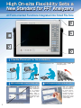
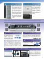
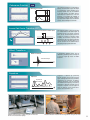
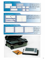
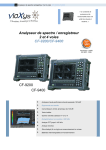
CF-7200
Portable 2-channel
Analyzer
CF -7200
Lightweight, compact and highly portable
The de facto standard for the next generation,
for worldwide use
CF -7200
Portable 2-channel FFT Analyzer
Flexible
Data Sharing
Accepts USB, Compact Flash Card, and
other general-purpose interfaces for
compatibility with PCs and easy data
sharing in the existing environment.
Intuitive Button
and Touch-panel
Operations
The CF-7200 needs no mouse - simply
press buttons for all operations. The clickfeel buttons and touch panel allow
immediate operations ranging from
start/stop of analysis to display of basic
functions.
An
An Advanced
Advanced FFT
FFT Analyzer
Analyzer
Covering
Covering Sophisticated
Sophisticated Needs
Needs on
on Site
Site
The CF-7200
Has Arrived
In this easy-to-use FFT analyzer designed for modern needs, all
aspects of the CF Series have been upgraded. With improved
PC compatibility and a much smaller size of the main body, the
CF-7200 delivers quick and easy measurement and analysis,
yet with exceptionally high accuracy. Integrating all on-site
needs into its compact body, the CF-7200 is a multifunctional high-performance analyzer that will become the de
facto standard for the next generation.
1
Lightweight, Compact and
Highly Portable for All Sites
No setup needed before measurement or troublesome installation on site, such as connecting
a personal computer, cables, and power supply to a measuring instrument.
All functions necessary for measuring and analyzing noise and vibration are built into the CF7200's small file size, for greater flexibility on all sites.
2
High On-site Flexibility Sets a
New Standard for FFT Analyzers
All Field-oriented Functions Integrated into Small File Size
Flexible Placement for Good Visibility
On a workbench
Vertically placed on
a desk
Highly Legible Large Screen with Easy Input
10.4-inch
3
Thanks to the 10.4inch TFT liquid crystal
display, detailed data
can be displayed
even though QUAD
display mode is
selected. Simple and
easy operation is also
possible by touch
panel.
Horizontally placed on a floor
360-degree rotary
setting at any angle
handle
for
Data Management by Entering Memos Directly
With the supplied
stylus pen, comments,
marks and memos can
be entered directly,
making it easier to
recognize the working
efficiency and data.
Memos can be saved
simultaneously and be
shown or hidden.
Intuitive Button Operations
Voice Memos Attached to Data
Equipped with a built-in
microphone for voice recording
and a speaker, voice memos
can be attached to data and
played back when the data is
displayed, supporting data
arrangements. There are also
connectors for connecting an
external
speaker
and
microphone, allowing you to
create voice memos even in a
noisy place.
Selection of main data of the FFT
analyzer, selection of the input voltage
range and frequency range, and
saving and loading of data can be
performed directly from the hardware
keys on the front panel. The CF-7200
offers simple, quick operations and
much more. Even when observing a
signal with unknown magnitude and
frequency, an appropriate range and
display conditions can be set with
intuitive continuous button operations.
And the signal output function can be
turned on or off with the hardware
keys, so signal output* can be started
or stopped with a simple ON/OFF,
preventing careless operations.
(* Option)
Input and Output Connectors Conveniently Arranged on Top
Automatic Sensor Data Input with TEDS
Each channel is equipped with a CCLD
(power supply for sensors) which can
directly drive an acceleration pickup, a
microphone, and other sensors
requiring a power supply. TEDS reads
data retained in a TEDS sensor and
then automatically supplies the power to
the sensor and performs unit calibration.
Direct Driving of Rotation Detector
Equipped with dedicated connectors which directly drive a rotation
detectors*1 and can be used as an external sampling clock. This
makes it easy to perform order ratio analysis*2 which analyzes
vibration and noise of engines, motors, and other rotating machinery
with rotation-based values.
* TEDS
* CCLD
TEDS, an abbreviation for Transducer Electronic
Data Sheet, is an information description format for
sensor-specific information, prescribed by the
IEEE1451 Series. When TEDS data is implemented
in a sensor, the sensor has a function called “plugand-play sensor” which allows sensor data
(sensitivity, weight, etc.) to be transmitted and
recognized by a measuring instrument connected.
As a result, troublesome unit calibration, which can
easily lead to errors, can be performed automatically.
CCLD, an abbreviation for
Constant Current Line Drive, is
a method for driving a constantcurrent type preamplifier
incorporated in a sensor. Either
an acceleration sensor or
microphone with a built-in
preamplifier can be driven by
connecting it to a signal input
terminal.
Cable Disconnection Detecting Function
Automatically detects cable disconnection of
an acceleration pickup and a microphone*,
preventing trouble before measurement.
* Intended for sensors with a built-in constantcurrent type preamplifier.
Panel for rack mounting (for special orders)
Ono Sokki offers a panel which enables the CF-7200 to be rack-mounted.
Visual and Aural Check of Phenomena
A raw signal coming from an acoustic or
vibration sensor connected to each channel
can directly be monitored as sound using a
headphone or an external speaker. This
makes it possible to check aurally whether an
intended vibration or sound is input correctly
as well as by waveform observation, allowing
you to check sensor setup and operation
intuitively and with your senses.
4
Meticulously Designed for
Easy Operation on Site
Smooth Operations on a Desk
USB Mass-storage Function with Direct PC Connection
Accepts Large-capacity CF Cards
The USB mass-storage function makes it possible to transfer data of the
CF-7200 to a PC through a USB cable* without having to remove a
storage medium and without needing special software (Windows XP).
Data can be recorded in a high-speed 2GB CF card (compact flash
memory card*), enabling long-time recording of a large volume of data.
R
* Recommended by Ono Sokki.
* USB connector mini-B type
Data Recording Function
CF card capacity (bytes) 512M
1G
2G
Recording time (approx.) 8 minutes 16 minutes 33 minutes*
2-channel, 100kHz-range, data only
*Maximum record time at single time
The data recording function for
recording a signal waveform in the CF7200 at a touch of the REC button
makes it possible to record long-time
phenomena, which are difficult to be
caught timely and the like in a memory
card*. The recorded data can then be
reproduced and analyzed on the CF7200 at a later time and place. Data
can also be analyzed using PC-based
sound and vibration analysis software.
* Recording form
at: ORF (Onosokki
Record Format)
Saving Data Simultaneously in Various Data Formats
The DAT format (binary), TXT format
and BMP format can also be saved
simultaneously. Data can also be
processed using Office software and
pasted into reports. Since the
underlying data in DAT format are
securely saved, data can be
displayed and processed using PCbased FFT software (DS-2000
Series, XN-8000 Series) and the CF
unit.
Diverse Data Processing on a Desk
Data recorded by the CF-7200 can be reproduced and analyzed by
various sound and vibration analysis software on a Windows - based PC.
R
* See page 11 for details.
5
Outdoor noise analysis using the CF-7200 and an LA Series Sound Level Meter
Highly Portable Analyzer for Use Anywhere
Weighs just 3.5kg
4-hour Battery Operation
The main unit of the
CF-7200
weighs
about 3.5kg*, thanks
to the simple and
compact body for
high portability.
* Excluding battery pack
By using the detachable lithium rechargeable battery, the unit can
run continuously for about 4 hours*. Measurement can be performed
freely, even outdoors or where no power supply.
* Without signal output, at 25℃ ambient temperature
Printing Function
Remote Control
Display data can be printed to a
USB-based thermal printer
recommended by Ono Sokki.
When the remote controller*
(DS-0295) is connected to
the CF-7200, three main
operations can be performed
in addition to analysis
start/stop. Operating the CF7200 from near the working
or supervising position
makes measurement much
easier.
* Option
State-of-the-art Technologies and
High Specifications, All in a Compact Body
Frequency range
Voltage input range
Data recording
Number of analysis points
Sound measurement of electronic components using the CF-7200 and an MI Series Microphone for measurement
10 mHz ∼100 kHz
10 mVr ∼31.62 Vr
100 kHz range max.,
2 channels
6400 points max.
6
ANALYSIS
New Possibilities for Measurement and Analysis, from Laboratories to Production Sites
Time-axis Waveform
Performs A/D conversion of the raw
waveform of an electrical signal of
vibration, noise, pressure, strain, etc.
coming from a sensor and then displays
the result as time-domain data. The Xand Y-axis values at any point can
directly be read using the search cursor.
The delta cursor function makes it easier
to read the time difference and level
difference.
Time-axis waveform
Time
Power Spectrum
Power spectrum
Magnitude
Frequency
The power spectrum indicates the
magnitude of frequency components
contained in a sampled time-axis
waveform. Frequency analysis enables
detection of abnormal conditions of a
facility, which are difficult to estimate
through measurement of vibration and
noise level and observation of raw timeaxis waveform. The natural frequency of a
structure can also be measured.
Frequency Response Function
Frequency response function
7
Hammering measurement with the CF-7200, GK-3100 Impulse
Hammer and an NP Series Acceleration pickup
The frequency response function indicates
the ratio of output to input and the frequency
characteristics of phase difference. The
resonant frequency and phase of a structure
can easily be obtained accurately by
entering the signal of vibration force
generated to Ch1 by an impulse hammer or
shaker and then inputting the response
(signal of acceleration, velocity and
displacement) to Ch2.
Analysis of micro-object using a LV Series Laser Doppler Vibration
Meter and an electromagnetic shaker
Coherence Function
The coherence function is for evaluating the
linearity and correlation of input and output
of a transmission system, obtained in the
frequency domain. The rate of contribution
of the input signal to the output signal is
represented as a digit from 0 to 1 for each
frequency, for evaluating the reliability of
the frequency response function, locating a
key factor from multiple noise and vibration
sources, and evaluating the correlation.
Coherence function
1.0
0
Inverse Fast Fourier Transform (IFFT)
Inverse Fast Fourier transform (IFFT)
IFFT
After frequency analysis, a time-axis waveform
of a selected band can be obtained again by
performing Inverse Fast Fourier Transform
(IFFT) for the selected frequency band. For
example, by selecting a waveform portion
excluding an unnecessary frequency band
confirmed in the FFT result and then performing
Inverse Fast Fourier Transform (IFFT) for it, a
time-axis waveform can be obtained with the
selected high frequency band eliminated.
Hilbert Transform
Hilbert transform
Time Envelope
A logarithmic damping factor can be
obtained by obtaining a time envelope of
a time-axis signal by means of Hilbert
transform.
Cepstrum
Cepstrum
Spectrum
Envelope
Vibration measurement in a plant using the CF-7200 and
an NP Series Acceleration pickup
Cepstrum is obtained by performing
Fourier transform of the power spectrum
again, allowing detection of the periodicity
contained in the spectrum. In addition,
reflected waveforms can be eliminated
and fundamental frequency extracted by
estimating a spectrum envelope from the
Cepstrum. Cepstrum can be applied to
make an analysis of the sound waves,
seismic waves, biowaves, etc.
Rotational vibration measurement of a large blower using the CF-7200
8
FUNCTION
Multiple Applications with a Single CF-7200
EU Function
EU Function
m /s2
m /s
m
Pa
N
Direct unit reading
The CF-7200 FFT analyzer can not only
directly read values as a voltage (V) but
also as a physical quantity. When the
input sensitivity has been set and
calibration with a reference signal
performed for each sensor, waveform
values are converted to physical
quantities when displayed, eliminating
the need to convert from voltage values
to physical quantities.
Average Summation UNDO Function
Average Summation UNDO Function
AVERAGE
SUMMATION
1.0
1.0
COH
COH
0
0
This function is used during average
summation to UNDO one average
summation. For example, if you end up
with a bad result of summation in
impulse hammer shaking, you can
cancel the result data (by UNDOing the
summation) and then try the summation
again.
UNDO
Differential and Integral Functions
Differential and Integral Functions
Integral
Integral
Acceleration
2
(m/s )
Differential
Differential
Integral
Velocity
(m/s)
Displacement
(m)
Differential
First and second order differential operations and
single and double integral operations are possible
for time-axis and frequency-axis waveforms.
Acceleration data from an acceleration sensor can
be converted to velocity and displacement; and
velocity data from a laser Doppler vibration meter
can be converted to acceleration and displacement
and displayed. When the EU function is used
together, unit conversion (among "m/s2", "m/s" and
"m") is also performed automatically.
List Display
This function displays a list of X-axis and Y-axis values for selected points on a
displayed waveform. Numeric list for 40 points selected, peak value list and harmonic list
enable numeric values to be simultaneously checked for multiple points.
9
Multi-screen
Display data can be arranged flexibly
in the SINGLE, DUAL, TRIPLE and
QUAD screen display modes. In the
DUAL, TRIPLE and QUAD screen
display modes, the difference
between screens can be viewed by
means of overlay display.
3
1
2
4
Zooming Analysis
In frequency analysis, zooming analysis is
possible by selecting a central frequency. This
function is useful for more detailed frequency
analysis, for example, analysis of beating and
other waveforms involving indistinguishable
adjacent frequency components.
Frequency Weighting Filters
FLAT
A weighting
C weighting
Frequency
weighting
filters such as A, C and
Flat
weighting
are
provided. can be applied
with A weighting and C
weighting. This makes it
easier to perform auditory
sense correction in
microphone-based
acoustic analysis.
10
A Variety of Software for Diverse Applications
Portable 2-channel FFT Analyzer
CF -7200
Measurement Processing Software
XN-8000 Series
Simultaneous analysis of multi-frequency
ranges, digital filtering and report creation
Multi-channel Data Station
DS-2000 Series
Application software for DS-2000 Series
Multi-functional Graph Creation Tool
OC-1000
Report & graph creation software
Applicable to commercial spreadsheet software
〈Functions〉
Function
〈Software〉
CF-7200 Data Format
Offline analysis
ORF format
Report
DAT format, TXT format, BMP format
Software
XN-8000 series
Model
XN-8100(Platform)
XN-0821(FFT analysis function)
General-purpose FFT analysis software DS-0221L
Report & graph creation software
11
* Refer to catalogs for details.
OC-1000
System Configuration of CF-7200
Diverse options and peripheral devices can be added according to intended applications, expanding the possibilities for the portable FFT analyzer.
Trigger Signal
Signal Output Connector
CF-0771 (Option)
Detectors
Rotation
MX-800
Series Cable
Peripherals
MP-981/LG-916
Remote Controller
DS-0295 (Option)
Rotation detectors
LV Series
Laser Doppler Vibrometer
Soft Carrying Case
CC-0025 (Option)
Stylus Pen CF-0702 (Standard accessory)
NP-3000
Series Acceleration Pickup with
Built-in Preamplifier
Hard Carrying Case
CC-0071(Option)
NP-0120/0130/0150 Series
Sensor Cable
NP-0021
Monitor Line Out
Vibration
NP-2000 Series
Charge Output
Acceleration Pickup
Panel Protection Cover
CF-0701 (Standard accessory)
NP-0120/0130/0150 Series
CH-6130/6140 Sensor Cable
Charge
Converter
Interfaces
Battery Pack CF-0792 (Standard accessory)
NP-3000 Series
3-axis Acceleration Pickup
Speaker
NP-0222/0252/0232/0262
NP-0021×3 Sensor Cable
Microphone
GK-3100 Impulse-force hammer
Printer
USB
LA Series
Sound Level meter
USB Memory
AX-501 Cable
Sound
MI-3110
Preamplifier
MX-100 Series
Cable
Other Amplifiers
MI-1233/MI-1431
Microphone
PC
DATA
CF-0703
USB Cable (Accessory)
MEDIA
CF Card
12
Specifications of Portable 2-channel FFT Analyzer CF-7200
1. Input Section
Number of input channels 2 Channels
Input configuration
Isolated single-ended
Input connector
DC offset
BNC (C02 type)
I EE E 1451.4(TEDS)
Accepts an IEEE1451.4 (TEDS)-based sensor
Input impedance
1MΩ±0.5% 100pF or less
Input coupling
DC
Amplitude
voltage range
Input range step
Input level monitor
Auto zero ON, -30 to -40dBVr range (DC coupling)
"TRIG ON" LED goes ON when trigger function turns ON
LED (TRIG'D) blinks when triggered
Position
-3dB at 0.5Hz or less Automatically set to AC when
CCLD is used.
−
Trigger
Absolute maximum input voltage 100VrmsAC for 1 minute (50Hz)
+30dBVr
+20dBVr
+10dBVr
0dBVr
−10dBVr
−20dBVr
−30dBVr
−40dBVr
Auto zero ON, +30 to -20dBVr range (DC coupling)
−40dB F.S. AUTO ZERO: Collective operation of all channels
Supplies the current to a constant-current type sensor via a coaxial
Power supply for sensor cable from the input connector (BNC terminal)
(CCLD)
+24V/4mA
AC
−60dB F.S. 31.62Vr
10.00Vr
3.162Vr
1.000Vr
0.3162Vr
0.100Vr
31.62mVr
10.00mVr
±8191
Mode
Free/Repeat/Single/One-shot
Source
1 channel/2 channels/External trigger signal
Slope
+/−/±
Hysteresis level
Arbitrary setup
Trigger level
Arbitrary setup
Input connector: BNC (C02 type)
Input voltage: ±10V
-40dBVr to 30dBVr in all 8 steps
External trigger
Input coupling: AC/DC
Input frequency: 100kHz max
Hysteresis level: Arbitrary setup (default 500mV)
Input impedance: 100kΩ
10d B
OVER
Over: Red LED ON (95% F.S. or more)
F IN E
Appropriate level: Green LED ON (-12dB F.S. or more)
Auto range
Whenever the 1-frame data is sampled, the amplitude voltage range
changes automatically if input range-over occurs.
A/D converter
16 bits
Dynamic range
90dB or higher: +30 to -30dBVr range 800 lines, Hanning window,
50 averages, 20℃, high-pass filter OFF
70dB or higher: -40dBVr range
Harmonic distortion
-80dB or less
Aliasing
-80dB or less
Amplitude flatness
20kHz or less ±0.1dB
20kHz to 100kHz ±0.2dB (0dBVr or less)
Filter
(Simultaneous use of
filters not possible)
A weighting filter, Conforms to IEC 60651-1979 TYPE1, ANSI S1.4-1983
C weighting filter TYPE1, and JIS 1505-1988 TYPE1
High-pass filter
10Hz(−18dB/oct)、100Hz(−18d B /oct)
Low-pass filter
1kHz(−18dB/oct)、10kHz(−18d B /oct)
Input voltage: ±10 V/TTL
Input impedance: 100kΩ
BNC (C02 type)
input
Input coupling: AC/DC
Hysteresis level: Arbitrary setup (default 500mV)
Input frequency: 256kHz (direct sampling not possible)
External sampling input
R03-R6F input
Full-scale accuracy
±0.1dB
at 1kHz
Amplitude linearity
±0.015%
at full scale
Cross-talk
-100dB or less
Gain accuracy
between channels
20kHz or less: ±0.1dB (0dBVr or less) Gain accuracy measured
20kHz to 100kHz: ±0.2dB (0dBVr or less) in the same voltage range
Remote control
Phase accuracy
between channels
Phase accuracy measured in the same
20kHz or less: ±0.5deg (0dBVr or less) voltage range with Equalize OFF
20kHz to 100kHz: ±1.0deg (0dBVr or less) Same voltage range ±0.1deg (typ.)
with Equalize ON
Voice input/output
for voice memo
MP-981or LG-916
rotation detector
(DC12V±0.6V, Max.
100mA)
ONO SOKKI's made
detectors
* BNC (C02 type) input or rotary encoder input is selected. Simultaneous input not possible
When the DS-0295 Remote Controller is connected, start/stop and
custom-selection operations are possible.
Sound input and playback with a built-in microphone and speaker
Voice memo can be stored by linking the measurement data.External connection has priority.
External MIC input: φ2.5 stereo mini jack input (L)
External SPEAKER output: φ3.5 stereo mini jack output (L)
2.Display Functions
Display mode
List display mode
Label function
SINGLE screen display mode/DUAL screen display mode/
TRIPLE screen display mode/QUAD screen display mode/OVERLAY display mode
Search function
Harmonic
Peak list display/Arbitrary point list/Octave list display
Input
Direct handwriting using a stylus pen
Color
8 colors
Line type
3 different thicknesses
Display
Show/hide
Vertical axis unit
Vertical axis scale
Delta function X mode/Y mode/XY mode
Partial OA/Peak/p-p/MAX-MIN/Search enhance
r m s /PEAK/0- p/p- p/V/V2/PSD /ESD
Automatic unit conversion function- Unit conversion by integral/
differential operations (displacement←→velocity←→acceleration)
Auto/Manual/Default/Gain/Phase unwrap function/Delay
Horizontal axis unit
H z/ r/m i n /Order (*under development) /s(sec)/EXT
Horizontal axis scale
Zooming with default/delta cursor
Calculation functions
Differential and integral operations/FRF equalization/Inverse Fast Fourier Transform/
Hilbert transform/Damping calculation by half-value width method
3.Display Unit
Size
10.4-inch
Resolution
800 x 600 dots
Type
TFT color LCD with touch panel function
Lighting (back light)
Cold-cathode tube, 2-level brightness adjustment
4. Analysis Section
Frequency accuracy
±0.005% of reading (±50ppm)
Frequency range
10mHz to 100kHz
Sampling frequency
Frequency range x 2.56 (internal sampling)
Number of sampling points Number of analysis points
256
100
512
200
1024
400
Number of sampling
800
points/analysis points 2048
4096
1600
8192
3200
16384
6400
Overlap processing
MAX/66.7%/50%/0%
Window functions
Rectangular/Hanning/Flat-top/Force/Exponential/User-defined
Delay function
Time frame of channel 2 can be delayed by 0 to 8191
points with reference to channel 1.
Time-axis waveform
processing function
The time-axis waveform processing function can be selected with soft keys.
First and second order differentials, Single and double integrals
Absolute value conversion/DC cancel/Trend elimination/Smoothing/Hilbert conversion
Real-time analysis
Search enhance
40kHz/2 channels (internal sampling: 4096 points)
Calculation resolution x32
Y-axis accuracy
±0.1d B
Setting of number of averages: 1 to 65535
Averaging setup time: 0.1 to 999 seconds (in 0.1-second steps)
Averaging can be stopped in terms of the number of times or time.
Averaging mode
FFT operation
Time domain
Summation average/Exponential average
Frequency domain
Summation average/Exponential average/Peak hold/
Subtraction average/Sweep average/Fourier average/Max OA
Amplitude domain
Summation average
A/D-over cancel/Double hammer cancel/
Averaging permission select function (ADD+1)/Averaging undo function
32-bit floating point (IEEE single-precision format)
5.Processing Functions
Time domain
Amplitude domain
Time-axis waveform/Auto-correlation function/Cross-correlation function/Impulse response/Cepstrum/Liftered envelope/Hilbert transform
Amplitude probability density function/Amplitude probability distribution function
Power spectrum/Fourier spectrum/Cross spectrum/Phase spectrum
Spectrum
Frequency domain
Frequency response
Real part/Imaginary part/Nyquist diagram/H1/H2/equalized waveform of FRT/Coherence function/Coherence output power/Coherence blanking
function (FRF)
Power spectrum to 1/1 octave/Power spectrum to 1/3 octave/Vibration sensory correction (horizontal/vertical)
Miscellaneous
13
6.Memory Functions
Data record
Frequency range
100kHz( M AX)
Recorded channels
Ch1&Ch2 (Max.100kHz),Recording of single channel is not possible.
Recording time
2GB: Approx. 33 minutes
(Ch1 and Ch2 at 100kHz)
Recording format
ORF
Max. recordable memory capacity 2GB (in a CF card slot)
Record number
Automatic numbering by main unit start/stop operation
Event mark number
Arbitrary numbering by [MARK] button operation
Analysis data can be saved simultaneously with three different formats:
DAT, TXT and BMP(TXT and BMP selectable).
Panel condition memory
10 types
Contents of panel
condition memory
Memorizes parameters which can reproduce all software and
hardware settings in the panel condition memory mode.
Voice memo memory
200 data items or less (depending on the CF card capacity)
Handwritten memo memory 200 data items or less (depending on the CF card capacity)
Main unit built-in memory (fixed) or CF card can be selected.
ORF
Off-line analysis
FFT analysis is possible at recording frequency range or lower.
Recording device
200 data items, 10 record data items
(depending on the CF card capacity)
Max. recordable
memory capacity
Data file
File format
Main unit built-in memory
x1 (Cannot be replaced by user)
Card slot (CF card)
x1
CF card insertion/
removal warning LED
When LED (green) is lit, insertion or
removal of memory card is inhibited.
7.Output Functions
Interface
USB
External SPEAKER output
Number of ports
2
Standard
USB Ver.1.1/2.0(High Speed)
USB (type A)
For USB1.1 printer/USB memory
DATA (mini B type)
For USB2.0 USB node function
Printer interface
Printer output
Device
USB
Accepts thermal printers of recommended model
On-line data
Source
Saved data
Number of connectors 1
Number of connectors 2
Maximum output 100mW or more
Output voltage 1Vrms F.S. ±1% for input voltage range F.S. (1kHz sine wave, 1MΩ load)
Monitor output
Each connector outputs Ch1 or Ch2 data
Impedance
8Ω
Voice memo
Play back
Source
Input signal (after analog filtering)
Connector
Accepts φ=3.5 stereo mini jack (L)
Connector
φ=2.5 monaural jack
Impedance
Approx. 33Ω
Output adjustment By software
8.Signal Output
(CF-0771) ― Option
Number of channels
1
Output connector
BNC (C02 type)
D/A converter
16 bits
Maximum output voltage
±10V (Amplitude + DC offset)
Amplitude resolution
Approx. 2.5mV
Offset resolution
Approx. 5mV
Output format
Unbalanced output
ON
LED goes on when ON.
Protection circuit
Short-circuit protection
OFF
LED goes off when OFF.
Isolation
No isolation
Sine wave
Output impedance
Output current
Frequency range
Output ON/OFF
No isolation between chassis and digital common
0Ω
Low impedance output (unbalanced)
50Ω
±10%
-70dB or less
Prescribed with 1V0-p amplitude value
Turned on or off with the SIGNAL OUT button(Turned off at the time of activation)
ON/OFF for each button
Swept sine
Pseudo random
Random
Zoom mode analysis
256 to 4096
Possible for all waveforms
±1.0dB or less
20kHz−100kHz
±0.2dB or less
0−20kHz
Continuous
Sine wave
About 1.41
Time setup is possible.
Swept sine
About 1.4 to 1.6
Interval 62.5μs to 524s (Can be set in 62.5-μs steps)
Single-shot
Burst
Band limiting not possible
Impulse
Analysis frame length
Can be set from 1 to 32767 in 1-cycle steps
Taper function
Output
waveform
50mA (If 10mA is exceeded, harmonic distortion,
flatness, and crest factor are not prescribed.)
Continuous
Output mode
Harmonic
distortion
0.1mHz to 100kHz (sine wave)
The output can be gradually increased or
decreased when the signal is turned on or off.
Taper rising time
Spectrum flatness
Crest factor
1ms to 32s (in 1-ms steps)
Taper falling time 1ms to 32s (in 1-ms steps)
Pseudo random 3.3 or less
Random
3.3 or less
Impulse
32.0 or less
Pink filter
Analog filter: -3dB/oct ±1.0dB (prescribed for 20Hz to 20kHz)
Clock
Date (year, month, day) and time (hour, minute, second)
Operation beep
Can be turned on or off (in conjunction with ON/OFF of warning beep)
Warning beep
Can be turned on or off (in conjunction with ON/OFF of operation beep)
9.Miscellaneous Functions
Condition view
List display of condition settings
Can be saved in the XML (Text) format of condition.
10.General Specifications
Power requirement Input voltage
10.5 to 16.5VDC
Power connector DC jack (EIAJ TYPE5) Outer side: Negative electrode, Inner side: Positive electrode
About 60 VA (AC adapter used) Power consumption
Outside dimensions
(not including
328mm(W) x 246mm(D) x 88mm(H) (battery not mounted)/328mm(W) x 246mm(D) x
the handle and protrusions) 120mm(H) (battery mounted)/Refer to outer dimensions for details
Suspension of chassis VESA standard 100 x 100 (mm)/Can be suspended by attaching a φ5 adapter
Operating temperature range 0 to +40℃
Storage temperature range -10 to +50℃(including an external secondary battery)
Stylus pen Functional grounding terminal Grounding terminal for noise elimination
Forced-air cooling by an electric fan
Main unit cooling
Operating noise 32.5dB(A) (Reference value)
Weight Approx. 3.5kg/Approx. 4.8kg (battery pack mounted)
11.AC Adapter
(SQ60W15P-03)
12.Battery Pack
Input voltage
100 to 240VAC
Battery
Input frequency
50/60Hz
Shape
Output voltage
Rating 15V
Output current
Rating 4A
Safety standard
Electrical Safety Law/CE/UL
Can be stored in the main unit (accessory)
Carrying handle position 0°(top level position)/30°
/60°
/90°
/110°
/130°
/180°(bottom level position)
(CF-0792)
Lithium ion secondary battery
Fixed to the rear section of the main unit (detachable)
Operating time
Operates for 4 hours under standard operating conditions (2ch FFT analysis/
Signal output option not mounted/25℃ room temperature with a new battery
Remaining battery
level display
Displays the remaining battery level when operating on the secondary battery
4-level display.
Minimum remaining battery level Displays a warning message and shuts down automatically.
Charge
Charged by the AC adapter when the main unit power is OFF.
Charge time
About 8 hours (power OFF)
14
〈Outer Dimensions〉
〈Main Unit 〉
Model Name
CF-7200
〈Options〉
Model Name
Product Name
Portable 2-channel FFT Analyzer
〈Standard Accessories〉
Product Name
Model Name
CF-0792 Battery Pack
CF-0701 Panel Protection Cover
CF-0702 Stylus Pen
CF-0703 USB Connection Cable
SQ60W15P-03 AC Adapter
Product Name
CF-0771 1Ch Signal Output Module
CC-0025 Soft Carrying Case
CC-0071 Hard Carrying Case
DS-0295 Remote Controller
Rack Mount Adapter
〈Recommended Products〉
Model Name
Product Name
SDCZ2512-J65A USB memory 512MB(Cruzer mini)
SDCFH- CF card 512MB (Sandisk Ultra)
512-903
SDCFH1024-903 CF card 1GB (Sandisk Ultra II)
BL-112UI Thermal printer
HM-131
Speaker microphone
*Outer appearance and specifications are subject to change without prior notice.
URL: http://www.onosokki.co.jp/English/english.htm
U.S.A. & CANADA
THAILAND
P.R.CHINA
WORLDWIDE
Ono Sokki Technology Inc.
2171 Executive Drive, Suite 400
Addison, IL. 60101 U.S.A.
Phone : 630-627-9700
Fax : 630-627-0004
E-mail : [email protected]
Ono Sokki (Thailand) Co., Ltd.
29/67 Moo 5 Tivanon Road, Pakkred,
Nonthaburi 11120, Thailand
Phone : 02-964-3884
Fax : 02-964-3887
E-mail : [email protected]
Ono Sokki Beijing Office
Beijing Jing Guang Center 3510
Hu Jia Lou, Chao Yang Qu
Beijing P.R.C. 100020
Phone : 010-6597-3113
Fax : 010-6597-3114
E-mail : [email protected]
Ono Sokki Co., Ltd.
1-16-1 Hakusan, Midori-ku,
Yokohama 226-8507, Japan
Phone : 045-935-3976
Fax : 045-930-1906
E-mail : [email protected]
on 100% Recycled Paper
CAT . NO. 1634-03E Printed in Japan 0610(LI) 2K