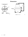
1
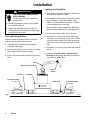
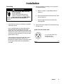
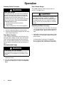
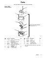
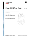
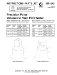
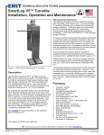
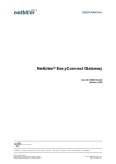
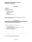
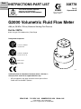
Parts
INSTRUCTIONS-PART LIST
308778
Contents
This manual contains important
warnings and information.
READ AND KEEP FOR REFERENCE.
Rev. C
Supersedes B
First choice when
quality counts.
INSTRUCTIONS
G3000 Volumetric Fluid Flow Meter
4000 psi (28 MPa, 276 bar) Maximum Working Fluid Pressure
Part No. 239716
0.02 to 1.0 gpm (75 to 3800 cc/min.) Flow Range
Recognized Component
Conforms to ANSI/UL
standard 2279
Certified to CAN/CSA
22.2 No. E79–11–95
EExia II A T4
D
98D.123385
*
7378A
Intrinsically Safe for Hazardous Locations (Class I; Division 1;
Group D) when used with an approved barrier only.
*
CE mark approvals only apply to meters used as part of Graco
ProMix and PrecisionMix II Systems.
GRACO INC.
P.O. BOX 1441
MINNEAPOLIS, MN
COPYRIGHT 1997, GRACO INC.
Graco Inc. is registered to I.S. EN ISO 9001
55440–1441
Table of Contents
Warnings . . . . . . . . . . . . . . . . . . . . . . . . . . . . . . . . . . . . . 3
Installation . . . . . . . . . . . . . . . . . . . . . . . . . . . . . . . . . . . . . 4
Operation . . . . . . . . . . . . . . . . . . . . . . . . . . . . . . . . . . . . . 6
Troubleshooting . . . . . . . . . . . . . . . . . . . . . . . . . . . . . . . . 7
Maintenance . . . . . . . . . . . . . . . . . . . . . . . . . . . . . . . . . . . 9
Flow Meter Parts . . . . . . . . . . . . . . . . . . . . . . . . . . . . . . 11
Dimensions . . . . . . . . . . . . . . . . . . . . . . . . . . . . . . . . . . . 12
Technical Data . . . . . . . . . . . . . . . . . . . . . . . . . . . . . . . . 13
Pressure Drop Curve . . . . . . . . . . . . . . . . . . . . . . . . . . 13
Warranty . . . . . . . . . . . . . . . . . . . . . . . . . . . . . Back Cover
Graco Phone Number . . . . . . . . . . . . . . . . . . Back Cover
Symbols
Warning Symbol
WARNING
This symbol alerts you to the possibility of serious
injury or death if you do not follow the instructions.
2
308778
Caution Symbol
CAUTION
This symbol alerts you to the possibility of damage to
or destruction of equipment if you do not follow the
instructions.
WARNING
INJECTION HAZARD
Spray from leaks, or ruptured components can inject fluid into your body and cause extremely serious
injury, including the need for amputation. Splashing fluid in the eyes or on the skin can also cause
serious injury.
Fluid injected into the skin might look like just a cut, but it is a serious injury. Get immediate medical attention.
Do not stop or deflect fluid leaks with your hand, body, glove, or rag.
Follow the Pressure Relief Procedure on page 6 whenever you: are instructed to relieve pressure; stop operation; or clean, check, or service the equipment.
Tighten all the fluid connections before operating the equipment.
Check the hoses, tubes, and couplings daily. Replace worn, damaged, or loose parts immediately.
FIRE, EXPLOSION, AND ELECTRIC SHOCK HAZARD
Improper grounding, poor air ventilation, open flames, or sparks can cause a hazardous condition and
result in fire or explosion and serious injury.
Ground the equipment as instucted in Grounding, page 5.
Never use the flow meter with an electrostatic gun isolation stand.
Keep liquids away from the electronic sensor device.
Follow the material supplier recommendations when flushing or servicing the meter.
Do not service the electronic sensor. Return it to your Graco distributor for service.
If there is any static sparking while using the equipment, stop spraying immediately. Identify and
correct the problem.
EQUIPMENT MISUSE HAZARD
INSTRUCTIONS
Equipment misuse can cause the equipment to rupture, malfunction, or start unexpectedly and result
in serious injury.
This equipment is for professional use only.
Read all instruction manuals, tags, and labels before operating the equipment.
Use the equipment only for its intended purpose. If you are uncertain about usage, call your Graco
distributor.
Do not alter or modify this equipment. Use only genuine Graco parts and accessories.
Check the equipment daily. Repair or replace worn or damaged parts immediately.
Do not exceed the maximum working pressure of the lowest rated system component. This equipment has a 4000 psi (28 MPa, 276 bar) maximum working pressure.
Use fluids or solvents that are compatible with the equipment wetted parts. See the Technical
Data section of all the equipment manuals. Read the fluid and solvent manufacturer’s warnings.
Comply with all applicable local, state and national fire, electrical and other safety regulations.
308778
3
Installation
Installing the Flow Meter
WARNING
FIRE, EXPLOSION, AND ELECTRIC
SHOCK HAZARD
To reduce the risk of fire, explosion, or
electric shock:
All electrical equipment must only be installed
by a qualified electrician.
Understand and follow your local code and
safety regulations for hazardous location wiring
of intrinsically safe circuits.
Dust and Foreign Matter
Avoid having dust or foreign matter enter the flow
meter by taking the following precautions:
Thoroughly flush the fluid supply lines before
installing the flow meter.
When installing fittings, make sure that no sealing
tape overlaps into the inside of the pipe.
Install a 100 mesh fluid filter upstream of the flow
meter.
Flow volume can only be measured at the location
where the flow meter is installed.
The G3000 Fluid Flow Meter is intrinsically safe for
Class I; Division 1; Group D hazardous indoor
(NEMA 1) locations when installed with an intrinsically safe power device and wiring.
Refer to ANSI standards ISA-RP12.6, NEC Article
504 and the Canadian Electrical Code Appendix F.
Do not use more than 200 ft. (61 m) of cable.
Refer to Fig. 1 to locate and install the flow meter,
connectors, and fluid shutoff valves. Install a check
valve to prevent backflow. The arrows on the flow
meter and check valve show the direction of fluid
flow.
The shutoff valves allow you to isolate the meter for
service.
Refer to the Technical Data and Dimensional
Drawings for dimension, inlet/outlet size, temperature and other specifications.
Cable
Electronic Sensor Device
Ground
Sheath
Fluid Line
Fluid Shutoff Valve
on outlet side
Check Valve
Fluid Shutoff Valve
on inlet side
7379A
Fig. 1
4
Flow Meter
308778
Installation
2. Always ground the fluid supply unit, using one of
the following options:
Grounding
WARNING
FIRE, EXPLOSION, AND ELECTRIC
SHOCK HAZARD
Proper electrical grounding of your
system is essential. For your safety,
read the warning section, FIRE, EXPLOSION, OR ELECTRIC SHOCK HAZARD, on
page 3.
1. Ground the flow meter by connecting a grounded
cable to the sensor.
Have a qualified electrician check the electrical
grounding continuity between the flow meter
sensor and a true earth ground; remove the cable
connector from the sensor and measure the resistance from the cable connector Pin B to true earth
ground. Refer to Fig. 2.
If the resistance is greater than 25 ohms, check
the cable ground connection. Refer to Fig. 2.
Reconnect the ground sheath or replace the cable.
Do not operate the system until the problem is
corrected.
a. Mount the meter to a grounded conductive
surface, or
b. Connect the conductive fluid hose to the meter
inlet and outlet, or
c.
Connect a ground wire to the meter’s M6
mounting holes.
3. Never use the flow meter with an electrostatic gun
isolation stand.
Cable Connector (Solder Side)
A +10–30 Vdc Supply (red)
B Ground (black)
C Signal Out (white)
7380A
Fig. 2
308778
5
Operation
Pressure Relief Procedure
WARNING
INJECTION HAZARD
The system pressure must be manually relieved to
prevent the system from starting or spraying accidentally. Fluid under high pressure can be injected
through the skin and cause serious injury. To
reduce the risk of an injury from injection, splashing
fluid, or moving parts, follow the Pressure Relief
Procedure whenever you:
are instructed to relieve the pressure,
stop spraying,
check or service any of the system equipment.
1. Turn off the fluid supply to the meter.
2. Shut off all electrical power to the fluid system.
3. Follow the Pressure Relief Procedure for your fluid
system dispensing device.
Flow Meter Function
This is a positive displacement, gear flow meter. The
gear flow meter is highly accurate, even with low flow
rates. The fluid flowing through the meter rotates the
gears. The gear tooth is picked up by a sensor device,
which produces an impulse for every gear tooth passing by.
Recommended Usage
WARNING
COMPONENT RUPTURE HAZARD
Do not exceed the maximum working pressure of
your meter or any component or accessory in your
system.
See the Technical Data for fluid and ambient
temperature limits.
Only use the flow meter with fluids that are compatible with the “Wetted Parts” listed in the Technical
Data.
6
308778
Flow Volume Range
The G3000 meter flow volume range is 0.02–1.0
gal./min. (75–3800 cc/min.).
CAUTION
The flow meter gears and bearings can be damaged
if they rotate at too high a speed. To avoid high
speed rotation, open the fluid valve gradually. Do not
over-speed the gear with air or solvent. To prolong
meter life, Do not use the meter above its maximum
flow rate.
Checking the Meter Accuracy
1. To check the accuracy of the meter, turn your gun
fan and atomizing air off, then trigger the fluid into
a graduated cylinder; dispense at least 500 cc of
fluid.
2. Measure the volume of fluid in the beaker in cubiccentimeters (cc) and read the volume on the flow
meter monitor.
If the flow meter scale factor is not between
0.112–0.140 cc/pulse, follow the cleaning procedure on page 10, then recalibrate the flow meter.
Troubleshooting
WARNING
NOTE: The sensor is not a serviceable part. Replace it
if it is malfunctioning.
INJECTION HAZARD
To reduce the risk of an injection injury or other
serious injury, follow the Pressure Relief Procedure on page 6 before checking or servicing the
meter assembly.
Problem
Cause
Solution
No flow volume displayed at monitoring unit
Flow volume is too low to measure
Increase flow volume.
Fluid is not flowing
See Problem: Fluid is not flowing,
below.
Damaged cable
Replace cable.
Improper input voltage to sensor
Make sure input power is 10–30 Vdc.
Damaged sensor
Replace sensor if it is malfunctioning.
Clogs in fluid line or in meter
Clean fluid line and/or meter; see
Maintenance section.
Gears worn or damaged
Service meter; see Maintenance
section.
Fluid is not flowing
308778
7
Notes
8
308778
Maintenance
WARNING
FIRE AND EXPLOSION HAZARD
If the meter is not installed in an intrinsically safe installation, make sure the
power is off or the electronic sensor is
disconnected before wiping the outside
of the meter clean with a cloth dampened in a compatible solvent or flushing
the meter.
CAUTION
Do not immerse the meter in solvent with the electronic sensor installed. Solvent could damage the
electrical components.
Air purge is not recommended for any gear-type flow
meter. Air purges do not provide the lubrication the meter gears require.
Flushing the Meter
WARNING
INJECTION HAZARD
To reduce the risk of an injection injury or other
serious injury, follow the Pressure Relief Procedure on page 6 whenever you are instructed to
relieve pressure.
Flush the fluid supply line and meter fluid reservoir
daily with a compatible solvent as instructed below.
1. Follow the Pressure Relief Procedure, on
page 6.
2. Connect the fluid line to the solvent supply unit.
Residue Build-up on the Meter Gears
Residue build-up may cause the meter gears to bind or
stop rotating, which decreases the meter accuracy and
makes meter recalibration necessary. As more build-up
occurs, recalibration is required more often.
The frequency that your meter requires cleaning
depends on the type of fluid being used. Excessive
residue build-up usually means that you are using
improper cleaning solvents and/or cleaning sequences
or processes.
3. Flush the meter until it is clean.
4. Follow the Pressure Relief Procedure, then
disconnect the fluid line from the solvent supply
unit.
5. Reconnect the fluid line to the fluid (paint) supply.
Check the meter routinely to develop the correct
cleaning schedule.
6. Turn on the fluid supply.
Use the proper cleaning solvent for the fluid being
metered.
7. Operate until the meter and fluid line are free of
solvent.
Maintenance continued on next page.
308778
9
Maintenance
Cleaning or Servicing the Meter Chamber
WARNING
INJECTION HAZARD
To reduce the risk of an injection injury or other
serious injury, follow the Pressure Relief Procedure on page 6 whenever you are instructed to
relieve pressure.
WARNING
FIRE, EXPLOSION, AND ELECTRIC
SHOCK HAZARD
Installing and servicing this equipment
requires access to parts that may cause
electric shock or other serious injury if
the work is not performed properly. Do not install or
service this equipment unless you are trained and
qualified.
Use only genuine Graco replacement parts. Substitution of components may impair intrinsic safety.
This could result in a failure which causes serious
injury and/or substantial property damage.
4. Loosen the two screws (1) and remove the electronic sensor device (2) from the flow meter upper
housing (5). See the parts drawing, page 11.
5. Loosen the screws (4). Keep a few threads of two
opposing bolts engaged to minimize the torque
stress on the shafts when you separate the meter
housings.
6. Hold onto the upper housing (5) and gently tap the
opposing bolts to separate the lower housing (11).
CAUTION
To avoid damaging the shafts (9), keep the housings
parallel to each other when separating them; do not
rock the housings from side to side. Do not use
chisels or screwdrivers to split and pry apart the
housings.
7. Remove and inspect the gears (8) and shafts (9).
Clean the meter parts with solvent.
8. Reassemble the gears and shafts into the lower
housing in the position they were removed from.
Check the gears for free and easy rotation.
9. Make sure the two locating pins (10) are in place.
NOTE: Clean and service the meter at a clean workbench. Use only lint-free cloth on parts.
1. Follow the Pressure Relief Procedure, on page
6. Then close the fluid shut-off valve on each side
of the meter.
2. Disconnect the cable from the electronic sensor
device.
3. Disconnect both fluid line fittings and remove the
meter from the fluid line.
10
308778
10. Assemble the two meter housings, making sure to
keep them parallel to each other.
11. Install the screws (4). Tighten them oppositely and
evenly, to 12 ft-lb (16 Nm). Do not over-tighten.
12. After re-assembling the meter, test the gear rotation by applying a brief air blast to the meter inlet.
You should clearly hear the gears spin.
13. Set the electronic sensor (2) on the upper housing
(5) and tighten the two screws (1) hand-tight,
about 3.5 ft-lbs (4.7 Nm). Do not over-tighten.
Parts
Use Only Genuine Graco Parts and Accessories
Model G3000
Part No. 239716
1
2
2a
4
5
7
8
Item 3, Gear Meter Assembly,
Includes items 4–11
9
10
11
12
7381A
Ref.
No.
1
Part No.
Description
Qty.
114100
2
2
239717
2a
3
290580
239719
4
5
7
110580
*
110588
SCREW, socket head; M4 x
55 mm long
ELECTRONIC SENSOR;
includes item 2a
LABEL, identification
GEAR METER ASSEMBLY;
includes items 4–12
SCREW
HOUSING, upper
O-RING; Teflon
1
1
1
Ref.
No.
8
9
10
11
12
*
10
1
1
Part No.
Description
Qty.
239718
192383
192387
*
290579
GEAR
SHAFT, gear
PIN, locating
HOUSING, lower
LABEL, identification
2
2
2
1
1
Not a replacement part. Order item 3, gear meter
assembly.
308778
11
Dimensions
Flow Meter Mounting Holes
(BOTTOM VIEW)
4.69 in.
119.13 mm
M6
1/4–18 npt(f)
inlet/outlet
2.16 in.
54.86 mm
3.35 in.
85.1 mm
1.73 in.
(43.94 mm)
7382A
12
308778
Weight: 6 lbs. (2.7 kg)
78983A
Technical Data
Category
Data
Category
Data
Maximum Working Fluid
Pressure
4000 psi (28 MPa,
276 bar)
Supply Voltage
10–30 Vdc
Intrinsic Safety
Flow Range
0.02–1.0 gal/min
(75–3800 cc/min)
Class 1; Div. 1; Group D
V max.= 30 V
I max. = 15 mA
Ci
= 0.2 mf
Li
= 0mH
Approvals
See front cover
Wetted Parts
303 Stainless Steel,
Tungsten Carbide,
Teflon
Fluid Temperature Range 40–180
F (4–80 C)
Maximum Ambient
Temperature
180
F (80 C)
Fluid Viscosity Range
20–3000 cps (Refer to
Pressure Drop Curve)
Maximum Cable Length
200 ft (61 m)
Flow Meter Inlet/Outlet
1/4 npt(f)
Teflon is a registered trademark of the DuPont Company.
Resolution
≈ 0.119 cc/pulse
Accuracy
+ 0.5 %*
* For most commonly used coatings, the flow meter reading
will be accurate to within + 0.5%. Accuracy will diminish at
low viscosities and low flow rates.
800 cps
1000 cps
140
1500 cps
PSI
2000 cps
3000 cps
Pressure Drop Curve
130
120
500 cps
110
100
400 cps
90
80
300 cps
70
60
50
200 cps
40
30
100 cps
20
30 cps
10
0
0.0
0.1
0.2
0.3
0.4
0.5
0.6
0.7
0.8
0.9
1.0
1.1 GAL/MIN
308778
13
Notes
14
308778
Notes
308778
15
The Graco Warranty and Disclaimers
Graco warrants all equipment listed in this manual which is manufactured by Graco and bearing its name to be free from defects in
material and workmanship on the date of sale by an authorized Graco distributor to the original purchaser for use. With the exception of
any special extended or limited warranty published by Graco, Graco will, for a period of twelve months from the date of sale, repair or
replace any part of the equipment determined by Graco to be defective. This warranty applies only when the equipment is installed,
operated and maintained in accordance with Graco’s written recommendations.
This warranty does not cover, and Graco shall not be liable for general wear and tear, or any malfunction, damage or wear caused by
faulty installation, misapplication, abrasion, corrosion, inadequate or improper maintenance, negligence, accident, tampering, or
substitution of non-Graco component parts. Nor shall Graco be liable for malfunction, damage or wear caused by the incompatibility of
Graco equipment with structures, accessories, equipment or materials not supplied by Graco, or the improper design, manufacture,
installation, operation or maintenance or structures, accessories, equipment or materials not supplied by Graco.
This warranty is conditioned upon the prepaid return of the equipment claimed to be defective to an authorized Graco distributor for
verification of the claimed defect. If the claimed defect is verified, Graco will repair or replace free of charge any defective parts. The
equipment will be returned to the original purchaser transportation prepaid. If inspection of the equipment does not disclose any defect
in material or workmanship, repairs will be made at a reasonable charge, which charges may include the costs of parts, labor, and
transportation.
Graco’s sole obligation and buyer’s sole remedy for any breach of warranty shall be as set forth above. The buyer agrees that no other
remedy (including, but not limited to, incidental or consequential damages for lost profits, lost sales, injury to person or property, or any
other incidental or consequential loss) shall be available. Any action for breach of warranty must be brought within two (2) years of the
date of sale.
GRACO MAKES NO WARRANTY, AND DISCLAIMS ALL IMPLIED WARRANTIES OF MERCHANTABILITY AND FITNESS FOR
A PARTICULAR PURPOSE IN CONNECTION WITH ACCESSORIES, EQUIPMENT, MATERIALS OR COMPONENTS SOLD BUT
NOT MANUFACTURED BY GRACO. These items sold, but not manufactured by Graco (such as electric motors, gas engines,
switches, hose, etc.), are subject to the warranty, if any, of their manufacturer. Graco will provide purchaser with reasonable assistance
in making any claim for breach of these warranties.
In no event will Graco be liable for indirect, incidental, special or consequential damages resulting from Graco supplying equipment
hereunder, or the furnishing, performance, or use of any products or other goods sold hereto, whether due to a breach of contract,
breach of warranty, the negligence of Graco, or otherwise.
FOR GRACO CANADA CUSTOMERS
The parties acknowledge that they have required that the present document, as well as all documents, notices and legal proceedings
entered into, given or instituted pursuant hereto or relating directly or indirectly hereto, be drawn up in English. Les parties
reconnaissent avoir convenu que la rédaction du présente document sera en Anglais, ainsi que tous documents, avis et procédures
judiciaires exécutés, donnés ou intentés à la suite de ou en rapport, directement ou indirectement, avec les procédures concernées.
Manual Change Summary
Manual was revised per ECO V6733 to change the front cover.
Graco Phone Number
TO PLACE AN ORDER, contact your Graco distributor, or call this number to identify the distributor closest to you:
1–800–367–4023 Toll Free
All written and visual data contained in this document reflects the latest product information available at the time of publication.
Graco reserves the right to make changes at any time without notice.
Sales Offices: Minneapolis, Detroit
Foreign Offices: Belgium, Korea, Hong Kong, Japan
GRACO INC.
P.O. BOX 1441
MINNEAPOLIS, MN
55440–1441
www.graco.com
16
308778
PRINTED IN U.S.A. 308778 September 1997 Revised August 1999