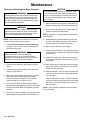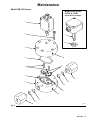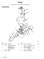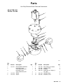
1
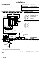
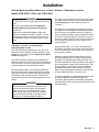
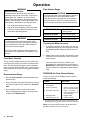
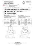
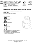
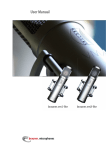
INSTRUCTIONS–PARTS LIST
308–243
Rev. B
Supersedes A
This manual contains important
warnings and information.
READ AND RETAIN FOR REFERENCE
Precision Pulse
Volumetric Fluid Flow Meter
Models Suitable for Class , Division 2 Use
Models Suitable for Class , Division 1 Use
2000 psi (140 bar) Maximum Fluid Working Pressure
3000 psi (210 bar) Maximum Fluid Working Pressure
MODEL
NO.
PART
NO.
FLUID
FLOW
VOLUME RANGE
gal/min (cc/min)
FLOW
MODEL
NO.
PART
NO.
FLUID
FLOW
VOLUME RANGE
gal/min (cc/min)
FLOW
PPM 3050
235–587
0.1136 cc
per tooth
0.01–0.5
(38–1900)
PPM
3050H
235–593
0.1136 cc
per tooth
0.01–0.5
(38–1900)
PPM 3100
235–588
0.2294 cc
per tooth
0.02–1.0
(75–3800)
PPM
3100H
235–594
0.2294 cc
per tooth
0.02–1.0
(75–3800)
PPM 3550
235–592
0.5883 cc
per tooth
0.1–5.5
(380–21,000)
PPM
3550H
235–589
0.5883 cc
per tooth
0.1–5.5
(380–21,000)
01538
Model PPM 3550 shown
01382
Model PPM 3550H shown
GRACO INC. P.O. BOX 1441 MINNEAPOLIS, MN 55440–1441
COPYRIGHT 1992 GRACO INC.
WARNINGS
Serious injury, explosion, fire or electric shock can occur if the precautions below are not followed.
Read and understand all instruction manuals, tags, and warning labels before operating equipment.
Electrical equipment shall only be installed, operated, and serviced by trained, qualified personnel who
shall be fully conversant with the requirements stated within this instruction manual.
FIRE, EXPLOSION OR ELECTRIC SHOCK HAZARD
All parts of the fluid system must be properly grounded
to reduce the risk of static electricity discharge. Sparks
can ignite fumes from solvents and the fluid being dispensed, dust particles and other flammable substances, whether you are spraying indoors or outdoors, and can cause a fire or explosion and serious
injury and property damage.
To reduce the risk of fire, explosion, or electric shock:
1. Always ensure proper grounding of the flow meter
through connection of a grounded cable to the
sensor.
2. Always ground the fluid supply unit and the fluid
supply line.
3. Never use the flow meter with an isolation stand.
If you experience any static sparking or feel even a
slight shock, turn off the power to the meter
immediately. Check the entire system for proper
grounding. Do not use the system again until the problem has been identified and corrected.
4. Do not spill water or other liquids on the electronic
sensor device.
Meter Models PPM 3050H, 3100H, and 3550H are
intrinsically safe for Class , Division 1, Group D hazardous indoor (NEMA 1) locations.
6. Do not service the electronic sensor. If the sensor
is not operating properly, you must return it to Graco for service.
Meter Models PPM 3050, 3100, and 3550 are suitable
for Class , Division 2, Group D hazardous indoor
(NEMA 1) locations.
5. Always follow the material suppliers’ Material
Specification Data Sheets whenever flushing or
servicing this meter.
7. Models PPM 3050, 3100, and 3550 only:
Do not disconnect the cable while the circuit is live
unless the location is known to be non-hazardous.
EQUIPMENT MISUSE HAZARD
General Safety
Any misuse of the meter such as over-pressurizing,
modifying or substituting parts, using incompatible
chemicals and fluids, or using worn or damaged parts,
can cause parts to rupture, and can result in serious
injury, electric shock, fire, explosion, or property
damage.
Always follow the Pressure Relief Procedure, at
right, before servicing or flushing the meter.
Never alter or modify any electrical components or circuits as this could cause a fire or explosion.
Use only genuine Graco replacement parts. Substitution of components may impair intrinsic safety.
Repair or replace worn or damaged parts immediately.
Fluid Compatibility
Be sure all fluids and solvents used are chemically
compatible with the ”Wetted Parts” shown in the Technical Data. Check the material data sheet or the fluid
manufacturer’s literature to see if the fluid is compatible with the meter’s wetted parts.
System Pressure
The Maximum Working Pressure of Meter Models
PPM 3050, 3100, and 3550 is 2000 psi (140 bar).
The Maximum Working Pressure of Meter Models
PPM 3050H, 3100H, and 3550H is 3000 psi (210 bar).
Never exceed the maximum working pressure of the
meter or of any component or accessory in your
system.
Never pressurize the flow meter without the electronic
sensor installed.
Pressure Relief Procedure
To reduce the risk of serious injury, including splashing
in the eyes or on the skin, or injury from moving parts,
fire, explosion, or electric shock, always follow this
procedure when shutting off the system, when checking or servicing any part of the spray system, and
whenever you stop operation.
1. Turn off the fluid supply to the meter.
2. Shut off all electrical power to the fluid system.
3. Follow the Pressure Relief Procedure for your fluid
system dispensing device.
IMPORTANT
United States Government safety standards have been adopted under the Occupational Safety and Health Act. These standards––particularly the General Standards, Part 1910 and the Construction Standards, Part 1926––should be consulted.
Table of Contents
Warnings . . . . . . . . . . . . . . . . . . . . . . . . . . . . . . . . . . . . . 2
Model PPM 3100H . . . . . . . . . . . . . . . . . . . . . . . . . 16
Installation . . . . . . . . . . . . . . . . . . . . . . . . . . . . . . . . . . . 4
Model PPM 3550H . . . . . . . . . . . . . . . . . . . . . . . . . 17
Operation . . . . . . . . . . . . . . . . . . . . . . . . . . . . . . . . . . . . . 8
Accessories . . . . . . . . . . . . . . . . . . . . . . . . . . . . . . . . . 18
Maintenance . . . . . . . . . . . . . . . . . . . . . . . . . . . . . . . . . . 9
Dimensions . . . . . . . . . . . . . . . . . . . . . . . . . . . . . . . . . . 20
Flow Meter Parts
Technical Data . . . . . . . . . . . . . . . . . . . . . . . . . . . . . . . 21
Model PPM 3050 . . . . . . . . . . . . . . . . . . . . . . . . . . 12
Pressure Drop Curve . . . . . . . . . . . . . . . . . . . . . . . . . 21
Model PPM 3100 . . . . . . . . . . . . . . . . . . . . . . . . . . 13
Safety Barrier Specifications . . . . . . . . . . . . . . . . . . 22
Model PPM 3550 . . . . . . . . . . . . . . . . . . . . . . . . . . 14
Warranty . . . . . . . . . . . . . . . . . . . . . . . . . . . . Back Cover
Model PPM 3050H . . . . . . . . . . . . . . . . . . . . . . . . . 15
Graco Phone Numbers . . . . . . . . . . . . . . . Back Cover
Installation
WARNING
Installing the Flow Meter
To reduce the risk of fire, explosion, or electric
shock, all electrical equipment must only be
installed by a qualified electrician.
Never install Models PPM 3050, 3100, and 3550 in
a Class I, Division 1 hazardous location. Only Models PPM 3050H, 3100H, and 3550H are suitable for
Class I, Division 1 hazardous location.
NOTE: Flow volume can only be measured at the location where the flow meter is installed.
Refer to Fig. 1 to locate and install the flow meter, connectors, and fluid shutoff valves.
Dust and Foreign Matter
The shutoff valves allow you to isolate the meter for
service. The gland, nut, and female connector shown
in Fig. 1 will ease removal of the flow meter from the
fluid line.
Avoid allowing dust or foreign matter from entering the
flow meter by taking the following precautions:
See Accessories to order these parts and other system components.
Thoroughly flush the fluid supply lines before
installing the flow meter.
When installing fittings, make sure that no sealing
tape overlaps into the inside of the pipe.
Refer to the Technical Data and Dimensional Drawings for dimension, inlet/outlet size, temperature and
other specifications.
NOTE: Do not use more than 200 ft. (61 m) of cable.
Install a 100 mesh fluid filter upstream of the flow
meter. See Accessories.
(Model PPM
3550H shown)
Flow Meter
Fluid Line
Electronic Sensor Device
Ground
Sheath
Fluid Shutoff Valve
on outlet side
Cable
*Gland
Fluid Shutoff Valve
on inlet side
Flow Meter
Fluid Line
*Nut
Fig. 1
*Male
Connector
TYPICAL RIGID TUBING INSTALLATION
Male x Female
Connector
Provided with Meter
01387
*Not provided. See Accessories to order.
Installation
Check the Electrical Grounding
WARNING
Remote Monitoring
The flow meters are designed for use with the Graco
PPD 200 Remote Displays. See Accessories for part
numbers and descriptions.
Proper electrical grounding of your system is
essential. For your safety, read the warning section, FIRE, EXPLOSION, OR ELECTRIC SHOCK
HAZARD, on page 2.
See Fig. 2 to connect the remote display to meter
models PPM 3050, 3100, and 3550.
See Fig. 3 to connect the remote display to meter
models PPM 3050H, 3100H, and 3550H.
Have a qualified electrician check the electrical
grounding continuity between the flow meter sensor
and a true earth ground. If the resistance is greater
than 25 ohms, check the cable ground connection; refer to the Fig. 2 wiring schematic. Reconnect the
ground sheath or replace the cable. Do not operate the
system until the problem is corrected.
See instruction manual 308–242 for more detailed
information on installing and connecting the PPD 200
Remote Display.
Remote Monitoring continued on next page.
Remote Display Connections for Meter used in Class , Division 2 Location
PPD 200 Remote Display
Cable Connector (Solder Side) for
Meter Models PPM 3050, 3100, & 3550
A +10–30 VDC Supply (red)
B Ground (black)
C Signal Out (white)
Cable Connector (Pin Side) for
Meter Models PPM 3050, 3100, & 3550
* Cable wire connections between meter and
remote display. Other wiring is factory installed.
Non-Hazardous
Location
Cable
Connector
Class , Division 2
Hazardous Location
Sensor
Flow Meter
Fig. 2
Meter Models PPM 3050, 3100, and 3550
Installation
Remote Monitoring
The flow meter will send an output pulse for each gear
tooth that passes the sensor. The actual K-factor for
your meter is marked on the data sheet included with
the meter. The approximate flow volume per one pulse
(K-factor) is shown at right.
METER MODEL NO.
K-FACTOR
PPM 3050 & 3050H
0.1136 cc per pulse
PPM 3100 & 3100H
0.2294 cc per pulse
PPM 3550 & 3550H
0.5883 cc per pulse
Remote Display Connections for Meter used in Class , Division 1 Location
Cable Connector (Solder Side) for Meter
Models PPM 3050H, 3100H, & 3550H
0.47 F
CAPACITOR
+8–30 VDC Supply (red)
Signal Out (white)
Ground (black)
not used
not used
Cable Connector (Pin Side) for Meter
Models PPM 3050H, 3100H, & 3550H
1
2
3
4
5
PPD 200 Remote Display
#12 AWG GREEN INSULATED WIRE
Intrinsic
Safety
Barrier
Must connect to
true earth ground
Sensor
Non-Hazardous
Location
Class , Division 1
Hazardous Location
Cable
Connector
Flow Meter
* Cable wire connections between meter and remote display.
Other wiring is factory installed.
Fig. 3
Meter Models PPM 3050H, 3100H, and 3550H
Installation
Remote Monitoring When Meter is in a Class , Division 1 Hazardous Location
Models PPM 3050H, 3100H, and 3550H ONLY
WARNING
To reduce the risk of fire and explosion and serious
injury:
Be sure to understand and follow Hazardous
Location Wiring of Intrinsically Safe Circuits
instructions.
When meter models PPM 3050H, 3100H, and
3550H are installed in a Class I, Division 1, Group
D hazardous location and a remote monitor is in a
non-hazardous location, a barrier module must be
used.
Hazardous (classified) Location Wiring of
Intrinsically Safe Circuits
The PPD 200 Remote Displays 235–613, 235–614,
and 235–615 have a barrier module installed. If using
another remote monitor, see the Safety Barrier Specifications on page 22.
The PPD 200 Remote Display barrier module has 6
terminals. Terminals 1 and 2 are for the non-hazardous
side connections. Terminals 3 and 4 are the intrinsically safe connections to the hazardous location.
Wiring beyond terminals 3 and 4 should maintain at
least a 2 inch (50 mm) separation from any non-intrinsically safe wiring and must be marked as Intrinsically
Safe Wiring at the required intervals. Field junction
boxes may be used as long as this separation is maintained.
WARNING
The cable must be sealed or vented at the point where
the cable enters and leaves the non-hazardous area.
(See Accessories for Graco cable seal, part no.
110–458.)
The purpose of such sealing or venting is to prevent
the cable from transmitting the flammable atmosphere
from one area of a hazardous location to another or
from a hazardous location to a non-hazardous location
at a rate of more than 198 cm3 of air per hour (h) at a
pressure of 1493 Pa (0.007 ft3/h of air at a pressure of
6 in. of water), with both ends of the cable at atmospheric pressure.
Along with terminals 1, 2, 3, and 4, two extra screw
terminals are provided, one on each side of the barrier.
They are conductively connected to the mounting rail
once properly installed.
Without grounding, Intrinsic Safety Barriers will not
provide voltage protection. Therefore, they must be
grounded to a designated grounding electrode. This
electrode should be the same potential as that used for
the non-hazardous location side instrumentation. The
ground conductor must be insulated from adjacent
grounded metal objects and no smaller than a #12
AWG. The grounding path resistance from the barrier
to this ground point must not exceed 1 ohm.
For further information on installation and wiring, refer
to ANSI standards ISA-RP12.6 Installation of
Intrinsically Safe Systems for Hazardous (Classified)
Locations, NEC Article 504 and the Canadian Electrical
Code Appendix F.
The transmitting of flammable atmosphere from
one area to another through a multi-conductor
cable can cause fire or explosion and result in
serious injury and property damage. Follow the
instructions below and refer also to NEC Article
504 and 4.3 of ANSI standards ISA-RP12.6.
Operation
WARNING
Pressure Relief Procedure
To reduce the risk of serious injury, including
splashing in the eyes or on the skin, or injury from
moving parts, fire, explosion, or electric shock,
always follow this procedure when shutting off the
system, when checking or servicing any part of the
spray system, and whenever you stop operation.
Flow Volume Range
CAUTION
The flow meter gear can be damaged if it rotates at
too high a speed. To avoid high speed rotation,
open the fluid valve gradually. Do not over-speed
the gear with air or solvent. To prolong meter life,
Do not use the meter above its maximum flow rate.
1. Turn off the fluid supply to the meter.
2. Shut off all electrical power to the fluid system.
3. Follow the Pressure Relief Procedure for your
fluid system dispensing device.
WARNING
To reduce the risk of component rupture, which
could cause serious injury, including fluid injection,
never pressurize the flow meter without the electronic sensor device installed.
Do not exceed the maximum working pressure of
your meter or any component or accessory in your
system.
Flow Meter Function
This is a positive displacement, gear flow meter. The
gear flow meter is highly accurate, even with low flow
rates. The fluid flowing through the meter rotates the
gears. The gear tooth is picked up by a sensor device,
which produces an impulse for every gear tooth passing by.
Recommended Usage
See the Technical Data for fluid and ambient temperature limits.
Only use the flow meter with fluids that are compatible with the “Wetted Parts” listed in the Technical
Data.
Do not allow the fluid to set in the flow meter.
Before shutting down the system, flush the meter
as instructed in Maintenance.
METER MODEL NO.
FLOW RANGE
gal/min (cc/min)
PPM 3050 & 3050H
0.01–0.5 (38–1900)
PPM 3100 & 3100H
0.02–1.0 (75–3800)
PPM 3550 & 3550H
0.1–5.5 (380–21,000)
Checking the Meter Accuracy
1. To check the accuracy of the meter, turn your gun
fan and atomizing air off, then trigger the fluid into
a graduated cylinder; dispense at least 500 cc of
fluid.
2. Measure the volume of fluid in the beaker in cubiccentimeters (cc) and read the volume on the flow
meter monitor.
If the flow meter accuracy is outside of your
acceptable limit, clean the meter as instructed in
Maintenance. If the problem continues, return the
meter to Graco for re-calibration or parts replacement.
PROBLEM: No Flow Volume Display
If there is no flow volume displayed at your monitor,
check the following:
CAUSE
SOLUTION
1. Flow volume is too low to 1. Increase flow volume.
be measured
2. Fluid is not flowing
2. Check for clogs in fluid
line or in the meter itself.
3. Poor cable connection
3. Check connection to
ensure it is tight and free
of contaminates.
4. Damaged cable.
4. Replace cable.
5. Damaged sensor unit.
5. Replace sensor.*
* Do not service the electronic sensor. If the sensor is not
operating properly, you must return it to Graco for service.
NOTE: See the PPD 200 instruction manual 308–242 for
detailed information on the remote monitor.
Maintenance
CAUTION
CAUTION
Do not immerse the meter in solvent. Solvent could
damage the meter’s electrical components.
Excessively long air purges can over-speed the
flow meter gears and cause over-heating of the
gears and gear shaft. This can result in premature
gear and shaft failure.
NOTE: Clean the outside of the meter with a soft cloth
dampened in a compatible solvent as needed.
Residue Build-up on the Meter Gears
Residue build-up affects the flow meter performance
by decreasing the meter accuracy and making meter
recalibration necessary. As more build-up occurs,
recalibration is required more often.
The frequency that your meter requires cleaning
depends on the type of fluid being used. Check the
meter routinely to develop a cleaning schedule.
Gear Rotation Binding
When using water-based fluids, residue build-up may
cause the meter gears to bind or stop rotating. This
usually means that improper cleaning solvents and/or
cleaning sequences or processes are being used.
Check the cleaning cycle sequence or cleaning process. Correct them if necessary. Be sure to use the
proper cleaning solvent for the fluid being metered.
Fluid Line Air Purges
If using air purges, remember that air purges do not
provide the lubrication the meter gears require. The
metered fluid normally provides lubrication.
If the gears or shafts show signs of over-heating (bluish discoloration), excessive wear, or binding, check
the cycle times and the air pressures used for the air
purges. Determine and resolve the cause of the problem before installing another meter in the system.
Flushing the Meter
Flush the fluid supply line and meter fluid reservoir daily with a compatible solvent as instructed below.
1. Follow the Pressure Relief Procedure, on
page 8.
2. Connect the fluid line to the solvent supply unit.
3. Flush the meter until it is clean.
4. Follow the Pressure Relief Procedure, then disconnect the fluid line from the solvent supply unit.
5. Reconnect the fluid line to the fluid (paint) supply.
6. Turn on the fluid supply.
7. Operate until the meter and fluid line are free of
solvent.
Maintenance continued on next page.
Maintenance
Cleaning or Servicing the Meter Chamber
WARNING
Installing and servicing this equipment requires access to parts that may cause electric shock or other serious injury if the work is not performed properly. Do not install or service this equipment unless
you are trained and qualified.
CAUTION
To avoid damaging the shafts (5), keep the housings parallel to each other when separating them;
do not rock the housings from side to side. Do not
use chisels or screwdrivers to split and pry apart
the housings.
7. Mark the positions of the gears (4) and shafts (5)
before removing them from the lower housing (3).
WARNING
Use only genuine Graco replacement parts. Substitution of components may impair intrinsic safety.
This could result in a failure which causes serious
injury and/or substantial property damage.
8. Remove and inspect the gears (4) and shafts (5).
Clean the meter parts with solvent.
NOTE: Clean and service the meter at a clean workbench. Use only lint-free cloth on parts.
9. Reassemble the gears and shafts into the lower
housing in the position they were removed from.
Check the gears for free and easy rotation.
1. Follow the Pressure Relief Procedure Warning,
on page 8. Then close the fluid shut-off valve on
each side of the meter.
WARNING
Models PPM 3050, 3100, and 3550 only:
To reduce the risk of fire or explosion, DO NOT
disconnect the cable while the circuit is live unless
the location is known to be non-hazardous.
2. Disconnect the cable from the electronic sensor
device.
3. Disconnect both fluid line fittings and remove the
meter from the fluid line.
4. Remove the electronic sensor device (1) from the
flow meter upper housing (2) by using a light
wrench on the sensor keyway. Do not twist the
meter housings (2 & 3). Refer to Fig. 4.
5. Loosen the hex bolts (9). Keep a few threads of
two opposing bolts engaged to minimize the torque
stress on the shafts when you separate the meter
housings.
6. Hold onto the upper housing (2) and gently tap the
opposing bolts to separate the lower housing (3).
10
308-243
NOTE: Replace the o-ring (8) whenever the meter is
disassembled.
10. Make sure the dowels (A) are in place.
11. Align the index marks (B). Then assemble the two
meter housings, making sure to keep them parallel
to each other.
12. Install the hex bolts (9). Tighten them oppositely
and evenly, hand-tight (11 ft-lb [15 Nm]). Do not
over-tighten.
13. After re-assembly, test the gear rotation by applying a brief air blast to the meter inlet. You should
clearly hear the gears spin.
14. Models PPM 3050, 3100, & 3550: Screw the electronic sensor device into the meter hand-tight; do
not over-tighten.
Model PPM 3050H, 3100H, & 3550H: Screw the
electronic sensor device all the way into the meter,
then back off 1/4 turn and tighten the locknut; do
not over-tighten.
NOTE: Avoid forcefully twisting the meter housings
during assembly.
Maintenance
Model PPM 3050 shown
Models PPM 3050H,
3100H, & 3100H
Sensor Device and Bolt
1
9
1
13
2
B
8
4
5
A
10
3
11
12
A
B
12
11
10
01384
Fig. 4
308-243
11
Parts
Use Only Genuine Graco Parts and Accessories
Model PPM 3050
Part No. 235–587
1
9
2
8
5
4
3
12
10
11
11
10
12
01384
Ref.
No.
1
2
Part No.
Description
110–571
ELECTRONIC SENSOR
HOUSING, upper;
not a replacement part
HOUSING, lower;
not a replacement part
GEAR
SHAFT
3
4
5
12
110–573
110–575
308-243
Qty.
1
1
1
2
2
Ref.
No.
Part No.
Description
7
8
9
10
110–579
110–588
110–580
188–323
11
12
103–338
185–886
PIN, locating; not shown
O-RING; PTFE SCREW
ADAPTOR; 1/4” bsp(m) x
1/4” npt(f)
O-RING; Viton
SPACER, PTFE Qty.
1
1
6
2
2
2
Parts
Use Only Genuine Graco Parts and Accessories
Model PPM 3100
Part No. 235–588
1
9
2
8
5
4
3
12
10
11
11
10
12
01385
Ref.
No.
1
2
Part No.
Description
110–571
ELECTRONIC SENSOR
HOUSING, upper;
not a replacement part
HOUSING, lower;
not a replacement part
GEAR
SHAFT
3
4
5
110–574
110–576
Qty.
1
1
1
2
2
Ref.
No.
Part No.
Description
7
8
9
10
110–579
110–588
110–580
188–323
11
12
103–338
185–886
PIN, locating; not shown
O-RING; PTFE SCREW
ADAPTOR; 1/4” bsp(m) x
1/4” npt(f)
O-RING; Viton
SPACER, PTFE Qty.
308-243
1
1
6
2
2
2
13
Parts
Use Only Genuine Graco Parts and Accessories
Model PPM 3550
Part No. 235–592
1
9
2
8
5
4
3
12
10
11
11
10
12
01535
Ref.
No.
1
2
Part No.
Description
110–571
ELECTRONIC SENSOR
HOUSING, upper;
not a replacement part
HOUSING, lower;
not a replacement part
GEAR
SHAFT
3
4
5
14
110–583
110–584
308-243
Qty.
1
1
1
2
2
Ref.
No.
Part No.
Description
7
8
9
10
110–579
110–588
110–580
188–323
11
12
103–338
185–886
PIN, locating; not shown
O-RING; PTFE SCREW
ADAPTOR; 1/4” bsp(m) x
1/4” npt(f)
O-RING; Viton
SPACER, PTFE Qty.
1
1
6
2
2
2
Parts
Use Only Genuine Graco Parts and Accessories
Model PPM 3050H
Part No. 235–593
1
9
13
2
8
5
4
3
12
10
11
11
10
12
01536
Ref.
No.
1
2
Part No.
Description
110–581
ELECTRONIC SENSOR
HOUSING, upper;
not a replacement part
HOUSING, lower;
not a replacement part
GEAR
SHAFT
PIN, locating; not shown
3
4
5
7
110–573
110–575
110–579
Qty.
1
1
1
2
2
1
Ref.
No.
Part No.
Description
8
9
10
110–588
110–580
110–586
11
12
13
110–587
185–885
105–776
O-RING; PTFE SCREW
ADAPTOR; M12 x 1.5(m) x
1/4” npt(f)
WASHER
SPACER, PTFE LOCK NUT
Qty.
308-243
1
10
2
2
2
1
15
Parts
Use Only Genuine Graco Parts and Accessories
Model PPM 3100H
Part No. 235–594
1
9
13
2
8
5
4
3
12
10
11
11
10
12
01537
Ref.
No.
1
2
Part No.
Description
110–581
ELECTRONIC SENSOR
HOUSING, upper;
not a replacement part
HOUSING, lower;
not a replacement part
GEAR
SHAFT
PIN, locating; not shown
3
4
5
7
16
110–574
110–576
110–579
308-243
Qty.
1
1
1
2
2
1
Ref.
No.
Part No.
Description
8
9
10
110–588
110–580
110–586
11
12
13
110–587
185–885
105–776
O-RING; PTFE SCREW
ADAPTOR; M12 x 1.5(m) x
1/4” npt(f)
WASHER
SPACER, PTFE LOCK NUT
Qty.
1
10
2
2
2
1
Parts
Use Only Genuine Graco Parts and Accessories
Model PPM 3550H
Part No. 235–589
1
9
13
2
8
5
4
3
12
10
11
11
10
12
01535
Ref.
No.
1
2
Part No.
Description
110–581
ELECTRONIC SENSOR
HOUSING, upper;
not a replacement part
HOUSING, lower;
not a replacement part
GEAR
SHAFT
PIN, locating; not shown
3
4
5
7
110–583
110–584
110–579
Qty.
1
1
1
2
2
1
Ref.
No.
Part No.
Description
8
9
10
110–588
110–580
110–586
11
12
13
110–587
185–885
105–776
O-RING; PTFE SCREW
ADAPTOR; M12 x 1.5(m) x
1/4” npt(f)
WASHER
SPACER, PTFE LOCK NUT
Qty.
308-243
1
10
2
2
2
1
17
Accessories
Use Only Genuine Graco Parts and Accessories
Meter Mounting Bracket 188–330
Connector 111–972
For mounting the meter to a wall or table.
7300 psi (511 bar) Maximum Working Pressure
For connecting between flow meter adapter and nut
111–969. See page 4. PTFE o-ring face seal.
1/4 npt(mbe)
Fluid Filter 223–160
5000 psi (350 bar) Maximum Working Pressure
With stainless steel bowl and polyethylene support
NOTE: Filter 223–160 has a 60 mesh screen. To help
prevent premature meter wear, the use of a 100 mesh
screen is recommended. Order Part No. 167–026
(100 mesh screen) when you order the filter.
Cable Seal 110–458
For intrinsically safe electrical cable. Provides a sealed
passageway for the cable from the Hazardous to the
Non-hazardous Locations.
100 Mesh Filter Screen 167–026
Electrical Cables
Recommended for use with Fluid Filter 223–160.
For connecting to sensor
Fluid Shutoff Valve
5000 psi (350 bar) Maximum Working Pressure
For shutting off the fluid and isolating the flow meter for
service or replacement. See page 4.
For Models PPM For Models PPM
3050, 3100,
3050H, 3100H,
& 3550
& 3550H
Cable Part No.
Cable Part No.
Cable Length
948–920
235–600
6 ft (1.83 m)
948–921
235–601
15 ft (4.58 m)
948–922
235–602
25 ft (7.63 m)
948–923
235–603
36 ft (10.98 m)
948–924
235–604
50 ft (15.25 m)
948–925
235–605
75 ft (22.88 m)
948–926
235–606
100 ft (30.5 m)
948–927
235–607
125 ft (38.13 m)
Female Nut 111–969
948–928
235–608
150 ft (45.75 m)
For connecting between 1/4 inch gland 111–970 and
1/4 npt(m) connector 111–972. See page 4.
948–929
235–609
200 ft (61 m)
PART NO.
210–657
210–658
210–659
DESCRIPTION
1/4 npt(mbe)
3/8 npt(mbe)
1/4 npt(m) x 3/8 npt(m)
Gland 111–970
7700 psi (531 bar) Maximum Working Pressure
For connecting rigid tubing to meter. See page 4.
1/4 inch tube socket
18
308-243
Accessories
Use Only Genuine Graco Parts and Accessories
PPD 200 Remote Display
PPD 200 Remote Display
For use with Flow Meters Located in Class ,
Division 1 Hazardous Locations
For use with Flow Meters Located in Class ,
Division 1 Hazardous Locations
PPD 200
PART NO.
FOR USE WITH
METER MODEL NO.
PPD 200
PART NO.
FOR USE WITH
METER MODEL NO.
235–610
PPM 3050
235–613
PPM 3050H
235–611
PPM 3100
235–614
PPM 3100H
235–612
PPM 3550
235–615
PPM 3550H
Rack Mounting Kit 235–590
Kit for rack mounting PPD 200 Display. Includes faceplate for display and instructions on how to install the
PPD 200 in a rack.
Remote Display, Flow Meter, & Cable Packages
Remote Display, Flow Meter, & Cable Packages
For use with Flow Meters Located in Class , Division 2 Hazardous Locations
For use with Flow Meters Located in Class , Division 1 Hazardous Locations
Includes:
Includes:
PACKAGE
PART NO.
METER
MODEL
DISPLAY
PART NO.
CABLE
LENGTH
ft (m)
PACKAGE
PART NO.
METER
MODEL
DISPLAY
PART NO.
CABLE
LENGTH
ft (m)
235–750
PPM 3050
235–610
25 (7.63)
235–770
PPM 3050H
235–613
25 (7.63)
235–751
PPM 3050
235–610
50 (15.25)
235–771
PPM 3050H
235–613
50 (15.25)
235–752
PPM 3050
235–610
100 (30.5)
235–772
PPM 3050H
235–613
100 (30.5)
235–753
PPM 3100
235–611
25 (7.63)
235–773
PPM 3100H
235–614
25 (7.63)
235–754
PPM 3100
235–611
50 (15.25)
235–774
PPM 3100H
235–614
50 (15.25)
235–755
PPM 3100
235–611
100 (30.5)
235–775
PPM 3100H
235–614
100 (30.5)
235–756
PPM 3550
235–612
25 (7.63)
235–776
PPM 3550H
235–615
25 (7.63)
235–757
PPM 3550
235–612
50 (15.25)
235–777
PPM 3550H
235–615
50 (15.25)
235–728
PPM 3550
235–612
100 (30.5)
235–778
PPM 3550H
235–615
100 (30.5)
308-243
19
Dimensions
DIM. A
1/4 npt(f)
inlet/outlet
DIM. A
DIM. B
DIM. B
DIM. C
DIM. C
DIM. D
DIM. D
1/4 npt(f)
inlet/outlet
01538
01382
Model No.
Dim. A
Dim. B
Dim. C
Dim. D
PPM 3050
4.24 in.
(107.70 mm)
2.00 in.
(50.80 mm)
3.33 in.
(84.58 mm)
5.90 in.
(149.86 mm)
PPM 3100
4.36 in.
(110.74 mm)
2.16 in.
(54.86 mm)
3.33 in.
(84.58 mm)
5.90 in.
(149.86 mm)
PPM 3550
4.83 in.
(122.68 mm)
2.63 in.
(66.80 mm)
3.33 in.
(84.58 mm)
5.90 in.
(149.86 mm)
PPM 3050H
5.10 in.
(129.54 mm)
2.00 in.
(50.80 mm)
3.33 in.
(84.58 mm)
5.90 in.
(149.86 mm)
PPM 3100H
5.26 in.
(133.60 mm)
2.16 in.
(54.86 mm)
3.33 in.
(84.58 mm)
5.90 in.
(149.86 mm)
PPM 3550H
5.73 in.
(145.54 mm)
2.63 in.
(66.80 mm)
3.33 in.
(84.58 mm)
5.90 in.
(149.86 mm)
Flow Meter Mounting Holes
(BOTTOM VIEW)
M6
1.73 in.
(43.94 mm)
Technical Data
Maximum Working Fluid Pressure
Flow Meter Inlet/Outlet Size without Connector
Models PPM 3050, 3100, 3550 . 2000 psi (140 bar)
Models PPM 3050H, 3100H, 3550H . . . . . 3000 psi
(210 bar)
Models PPM 3050, 3100, 3550 . . . . . . . . 1/4 bsp(m)
Models PPM 3050H, 3100H, 3550H . . M12 x 1.5(m)
Maximum Fluid Temperature
Flow Range
Models PPM 3050/3050H . . . . . . . 0.01–0.5 gal/min
(38–1900 cc/min)
Models PPM 3050, 3100, 3550 . . . 180_ F (80_ C)
Models PPM 3050H, 3100H, 3550H . . . . . . 250_ F
(120_ C)
Models PPM 3100/3100H . . . . . . . 0.02–1.0 gal/min
(75–3800 cc/min)
Maximum Ambient Temperature . . . 113_ F (45_ C)
Models PPM 3550/3550H . . . . . . . . 0.1–5.5 gal/min
(380–21,000 cc/min)
Fluid Viscosity Range . . . . . . . . . . . . . . . . . 15,000 cps
(Refer to the Pressure Drop Curve, below)
Maximum Cable Length . . . . . . . . . . . . . . 200 ft (61 m)
Flow Meter Connector Size
Models PPM 3050, 3100, 3550 . . . . . . . 1/4 bsp(m)
x 1/4 npt(f)
Models PPM 3050H, 3100H, 3550H . . M12 x 1.5(m)
x 1/4 npt(f)
Wetted Parts . . . . . . . . . . . . 303 & 321 Stainless Steel,
Tungsten Carbide, PTFE r
PTFE r is a registered trademark
PSI
For most commonly
used coatings, the flow
meter will provide accurate flow readings to
within + 0.5%.
FLOW RATE
Pressure Drop Curve
PPM 3050/3050H
PPM 3100/3100H
0
0.10
0.20
0.30
0.40
0.50
0.60
0.70
0.80
0.90
1.00 1.10
PPM 3550/3550H
0
0.32
0.65
0.97
1.30
1.62
1.94
2.27
2.59
2.92
3.24 3.43
GAL/MIN
308-243
21
Safety Barrier Specifications
WARNING
To maintain intrinsic safety of your installation, only
replace the Stahl barrier fuse with 160 mA
replacement fuse, Stahl Part No. 011239.
Stahl Model No. 9002/13–280–110–00
R. Stahl, Inc.
Intrinsic Safety Barrier
Outputs are Intrinsically Safe for Class I, Division 1,
Groups A, B, C, D at 40 C.
NOTE: This barrier is included with Graco PPD 200
Remote Displays 235–613, 235–614, and 235–615.
Terminal Connections
Terminal 1: Non-hazardous connection for supply
voltage
Terminal 2: Non-hazardous connection for signal
Terminal 3: Hazardous connection for supply voltage
Terminal 4: Hazardous connection for signal
Channel Operational Data
Rated Voltage: 24 VDC
Maximum Voltage: 26 VDC
Fuse Current (I): 160 mA
End-to-End Resistance (R): 280 W
Safety Description in accordance to standards issued by
Factory Mutual–Class No. 3610–October 1988 (entity
concept parameters) for Channel I, terminal 3, supply
voltage to ground
Open Circuit Voltage (V oc): 28 VDC
Short Circuit Current (I sc): 109.1 mA
Allowed External Capacitance (Ca): 0.39 mF
Allowed External Inductance (La): 11.6 mH
Safety Description in accordance to standards issued by
CSA–22.2 No. 157
Open Circuit Voltage (V oc): 28.4 VDC
Minimum Resistance (R): 257 W
Channel Operational Data
Rated Voltage: 24 VDC
Maximum Voltage: 26 VDC
Fuse Current (I): 160 mA
End-to-End Resistance (R):
1 V < 22 mA
2 V > 22 mA
Safety Description in accordance to standards issued by
Factory Mutual–Class No. 3610–October 1988 (entity
concept parameters) for Channel II, terminal 4, signal to
ground
Open Circuit Voltage (V oc): 28 VDC
Short Circuit Current (I sc): 0.0 mA
Allowed External Capacitance (Ca): 0.39 mF
Allowed External Inductance (La): 1000 mH
Safety Description in accordance to standards issued by
CSA–22.2 No. 157
Open Circuit Voltage (V oc): 28.4 V
Minimum Resistance (R): diode
Notes
The Graco Warranty and Disclaimers
WARRANTY
Graco warrants all equipment manufactured by it and bearing its name to be free from defects in material and workmanship on
the date of sale by an authorized Graco distributor to the original purchaser for use. As purchaser’s sole remedy for breach of this
warranty, Graco will, for a period of twelve months from the date of sale, repair or replace any part of the equipment proven defective. This warranty applies only when the equipment is installed, operated and maintained in accordance with Graco’s written recommendations.
This warranty does not cover, and Graco shall not be liable for, any malfunction, damage or wear caused by faulty installation,
misapplication, abrasion, corrosion, inadequate or improper maintenance, negligence, accident, tampering, or substitution of
non–Graco component parts. Nor shall Graco be liable for malfunction, damage or wear caused by the incompatibility with Graco
equipment of structures, accessories, equipment or materials not supplied by Graco, or the improper design, manufacture, installation, operation or maintenance of structures, accessories, equipment or materials not supplied by Graco.
This warranty is conditioned upon the prepaid return of the equipment claimed to be defective to an authorized Graco distributor
for verification of the claim. If the claimed defect is verified, Graco will repair or replace free of charge any defective parts. The
equipment will be returned to the original purchaser transportation prepaid. If inspection of the equipment does not disclose any
defect in material or workmanship, repairs will be made at a reasonable charge, which charges may include the costs of parts,
labor and transportation.
DISCLAIMERS AND LIMITATIONS
The terms of this warranty constitute purchaser’s sole and exclusive remedy and are in lieu of any other warranties (express or
implied), including warranty of merchantability or warranty of fitness for a particular purpose, and of any non–contractual
liabilities, including product liabilities, based on negligence or strict liability. Every form of liability for direct, special or consequential damages or loss is expressly excluded and denied. In no case shall Graco’s liability exceed the amount of the purchase price.
Any action for breach of warranty must be brought within two (2) years of the date of sale.
EQUIPMENT NOT COVERED BY GRACO WARRANTY
Graco makes no warranty, and disclaims all implied warranties of merchantability and fitness for a particular purpose, with
respect to accessories, equipment, materials, or components sold but not manufactured by Graco. These items sold, but not
manufactured by Graco (such as electric motor, switches, hose, etc.) are subject to the warranty, if any, of their manufacturer.
Graco will provide purchaser with reasonable assistance in making any claim for breach of these warranties.
Graco Phone
Numbers
Manual
Change Summary
TO PLACE AN ORDER, contact your Graco distributor,
or call Graco: 1–800–328–0211 Toll Free
FOR TECHNICAL ASSISTANCE, service repair information or answers about the application of Graco equipment, call: 1–800–543–0339 Toll Free
The manual was changed from Rev. A to Rev. B to
eliminate the part numbers for the upper and lower
housings on all meter models as they are not replacement parts.
Sales Offices: Atlanta, Chicago, Dallas, Detroit, Los Angeles, Mt. Arlington (N.J.)
Foreign Offices: Canada; England; Korea; Switzerland; France; Germany; Hong Kong; Japan
GRACO INC.
P.O. BOX 1441 MINNEAPOLIS, MN
PRINTED IN U.S.A.
308–243 10/92 Revised 9/93
55440–1441