1
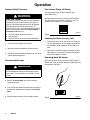
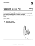
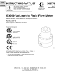
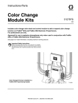
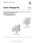
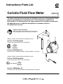
Instructions–Parts List
Coriolis Fluid Flow Meter
309234H
EN
The meter and meter kit are intended for installation and use on a PrecisionMix II fluid
panel in non–hazardous environments only. If a Coriolis meter is installed on a
PrecisionMix II, the entire system is no longer approved for a hazardous environment.
Not approved for use in explosive atmospheres or hazardous locations.
For professional use only.
Important Safety Instructions
Read all warnings and instructions in this manual and
in your proportioner manual. Save these instructions.
5000 psi (34 MPa, 345 bar) Maximum Working Pressure
Part No. 116158 Bare Meter
.01 to 0.5 gpm (40 to 2,000 cc/min.) Flow Range.
Part No. 244039 Meter Kit
Includes Part No. 116158 Bare Meter, mounting hardware, and fittings.
TI0624a
2300 psi (16 MPa, 160 bar) Maximum Working Pressure
Part No. 15D135 Bare Meter
.01 to 0.5 gpm (40 to 2,000 cc/min.) Flow Range.
II 2 G EEx de IIC
Part No. 15D599 Meter Kit
Includes Part No. 15D135 Bare Meter, mounting hardware, and fittings.
Table of Contents
Warnings . . . . . . . . . . . . . . . . . . . . . . . . . . . . . . . . . . . . . 3
Installation . . . . . . . . . . . . . . . . . . . . . . . . . . . . . . . . . . . . . 4
Operation . . . . . . . . . . . . . . . . . . . . . . . . . . . . . . . . . . . . . 6
Parts . . . . . . . . . . . . . . . . . . . . . . . . . . . . . . . . . . . . . . . . . 9
Dimensions . . . . . . . . . . . . . . . . . . . . . . . . . . . . . . . . . . . 10
2
309234
Technical Data . . . . . . . . . . . . . . . . . . . . . . . . . . . . . . . .
Wiring Diagram . . . . . . . . . . . . . . . . . . . . . . . . . . . . . . .
Warranty . . . . . . . . . . . . . . . . . . . . . . . . . . . . . . . . . . . . .
Graco Information . . . . . . . . . . . . . . . . . . . . . . . . . . . . .
11
12
14
14
WARNING
SKIN INJECTION HAZARD
Spray from leaks, or ruptured components can inject fluid into your body and cause extremely serious
injury, including the need for amputation. Splashing fluid in the eyes or on the skin can also cause
serious injury.
Fluid injected into the skin might look like just a cut, but it is a serious injury. Get immediate surgical treatment.
Do not stop or deflect fluid leaks with your hand, body, glove, or rag.
Follow the Pressure Relief Procedure on page 6 whenever you: are instructed to relieve pressure; stop operation; or clean, check, or service the equipment.
Tighten all the fluid connections before operating the equipment.
Check the hoses, tubes, and couplings daily. Replace worn, damaged, or loose parts immediately.
FIRE, EXPLOSION, AND ELECTRIC SHOCK HAZARD
Improper grounding, poor air ventilation, open flames, or sparks can cause a hazardous condition and
result in fire or explosion and serious injury.
Ground the equipment as instructed in Grounding, page 5.
Never use the flow meter with an electrostatic gun isolation stand.
Keep liquids away from the electronic sensor device.
Follow the material supplier recommendations when flushing or servicing the meter.
Do not service the electronic sensor. Return it to your Graco distributor for service.
If there is any static sparking while using the equipment, stop spraying immediately. Identify and
correct the problem.
EQUIPMENT MISUSE HAZARD
INSTRUCTIONS
Equipment misuse can cause the equipment to rupture, malfunction, or start unexpectedly and result
in serious injury.
This equipment is for professional use only.
Read all instruction manuals, tags, and labels before operating the equipment.
Use the equipment only for its intended purpose. If you are uncertain about usage, call your Graco
distributor.
Do not alter or modify this equipment. Use only genuine Graco parts and accessories.
Check the equipment daily. Repair or replace worn or damaged parts immediately.
Do not exceed the maximum working pressure of the lowest rated system component. See manual
cover for pressure rating.
Use fluids or solvents that are compatible with the equipment wetted parts. See the Technical
Data section of all the equipment manuals. Read the fluid and solvent manufacturer’s warnings.
Comply with all applicable local, state and national fire, electrical and other safety regulations.
309234
3
Installation
WARNING
FIRE, EXPLOSION, AND ELECTRIC
SHOCK HAZARD
To reduce the risk of fire, explosion, or
electric shock:
All electrical equipment must only be installed
by a qualified electrician.
Mounting the Flow Meter
CAUTION
The bare meter weighs 33 lb (15 kg). Do not mount
the meter in the fluid line without proper support, to
prevent stress on the fluid inlet and outlet connections. See Fig. 1.
Understand and follow your local code and
safety regulations for hazardous location wiring
of explosion proof circuits.
Dust and Foreign Matter
Avoid having dust or foreign matter enter the flow
meter by taking the following precautions:
Thoroughly flush the fluid supply lines before
installing the flow meter.
TI0850A
When installing fittings, make sure that no sealing
tape overlaps into the inside of the pipe.
Fig. 1
Installing the Flow Meter
No special fittings or brackets are required for mounting. External vibration will not affect the accuracy of
the meter.
Flow volume can only be measured at the location
where the flow meter is installed.
The meter is safe for Class I; Division 1; Group D
hazardous indoor (NEMA 1) locations when
installed in accordance to NEC power requirements.
Refer to ANSI standards ISA-RP12.6, NEC Article
504 and the Canadian Electrical Code Appendix F.
Do not use more than 200 ft (61 m) of cable.
4
309234
To prevent turbulence and cavitation in the fluid line, be
sure the line is adequately sized and contains a minimal number of restrictions (such as valves or bends).
For mounting dimensions, refer to page 10.
Continued on page 5.
Installation
Vertical Mounting
Grounding
When mounting on a vertical surface, the preferred
fluid flow is upward through the meter. See Fig. 2. This
allows solids to settle out and air to rise away from the
metering tube. This also allows thorough draining of
the meter during shutdown, to prevent fluid from drying
in the meter.
Downward flow is permitted if a check valve is installed
at the meter outlet to prevent fluid from falling through
the meter.
Fluid Flow
Do not mount the meter so the fluid line runs horizontally across the vertical mounting surface.
WARNING
FIRE, EXPLOSION, AND ELECTRIC
SHOCK HAZARD
Proper electrical grounding of your
system is essential. For your safety,
read the warning section, FIRE, EXPLOSION, AND ELECTRIC SHOCK HAZARD, on
page 3.
1. Ground the flow meter by connecting a grounded
cable to the sensor. Part No. 116005 Cable is
available (must be ordered separately).
Have a qualified electrician check the electrical
grounding continuity between the flow meter
sensor and a true earth ground; remove the cable
connector from the sensor and measure the resistance from the cable connector Pin A to true earth
ground. Refer to the Wiring Diagram on page 12.
Fluid Flow
If the resistance is greater than 25 ohms, check
the cable ground connection. Reconnect the
ground sheath or replace the cable. Do not operate the system until the problem is corrected.
TI0850A
Fig. 2
Horizontal Mounting
When mounting on a horizontal surface, the meter
transmitter must be either above or below the fluid line.
This ensures that solids do not collect and air does not
become trapped in the metering tube. See Fig. 3.
2. Always ground the fluid supply unit, using one of
the following options:
a. Mount the meter to a grounded conductive
surface, or
b. Connect the conductive fluid hose to the meter
inlet and outlet, or
Transmitter
c.
Fluid Flow
Fig. 3
Fluid Flow
TI0850A
Connect a ground wire to the meter’s 1/4–20
unc mounting holes.
3. Never use the flow meter with an electrostatic gun
isolation stand.
309234
5
Operation
Pressure Relief Procedure
WARNING
INJECTION HAZARD
The system pressure must be manually relieved to
prevent the system from starting or spraying accidentally. Fluid under high pressure can be injected
through the skin and cause serious injury. To
reduce the risk of an injury from injection, splashing
fluid, or moving parts, follow the Pressure Relief
Procedure whenever you:
are instructed to relieve the pressure,
stop spraying,
check or service any of the system equipment.
1. Turn off the fluid supply to the meter.
Flow Volume Range (60 Series)
The meter flow volume range is 0.01–0.5 gpm
(40–2,000 cc/min.).
Unscrew the meter cover to access the DIP switches.
The DIP switches must be set as shown in Fig. 4 to
ensure that the volume is 0.1 ml per pulse.
TI0851A
Fig. 4
Checking the Meter Accuracy (All)
1. To check the accuracy of the meter, turn your gun
fan and atomizing air off, then trigger the fluid into
a graduated cylinder; dispense at least 500 cc of
fluid.
2. Shut off all electrical power to the fluid system.
3. Follow the Pressure Relief Procedure for your fluid
system dispensing device.
2. Measure the volume of fluid in the beaker in cubiccentimeters (cc) and read the volume on the flow
meter/PrecisionMix II monitor.
Operating Mode (60 Series)
Recommended Usage
Unscrew the meter cover to access the DIP switches.
Set the ON switch to the DIP position for operation and
configuration. See Fig. 5.
WARNING
COMPONENT RUPTURE HAZARD
Do not exceed the maximum working pressure of
your meter or any component or accessory in your
system.
See the Technical Data for fluid and ambient
temperature limits.
Only use the flow meter with fluids that are compatible with the “Wetted Parts” listed in the Technical
Data.
Purge the meter housing as local codes require.
6
309234
DIP
Fig. 5
TI0851A
Operation
Measuring values
Using the ProMass 80A with a Graco
PrecisionMix II System
The following will list values per the E&H function
matrix. If a value isn’t mentioned, the the default E&H
settings will suffice.
Generic Settings for Basic Installation with a
PrecisionMix II System
The function matrix is a two level construct: groups
and functions.
The groups, being the highest level, are compromised
by multiple functions. In order to select the individual
functions that will control or parameterize the measuring device, you must first select a group.
NOTE: For an overview of the functions available see
page 8.
1. Using the function matrix press
group options.
.
.
3. To select a group option, press
Once you select a group, the functions related to
that group will follow.
4. To scroll through functions, press
5. To select a function, press
or
Group
Parameter
Value
System Units
Volume Flow
cc/m
Unit Volume
cc
Totalizer
Reset Total
Yes
Current
Output
(Mass Flow)
Assign
Current
Off
Pulse/Freq.
Output
Operation
Mode
Pulse
Assign Pulse
Volume
Pulse Value
.119 cc/pulse
Pulse Width
1.000 ms
Output Signal
Passive/Positive
On–Val.
Lf–Cut off
30.000 cc/min
.
.
6. To return back to the previous option, press
and
NOTE: To enable programming of the meter you will
need to enter the personal code. The factory setting is
80.
to access
2. To scroll through the group options, press
or
The table below shows the minimum required settings
for use with a Graco PrecisionMix II system.
Process
Parameter
Maintenance
.
CAUTION
NOTE: Once you press
, your selection is saved.
The fluid meter has no field-serviceable parts. Contact your Graco distributor for service.
309234
7
8
309234
LANGUAGE
ASSIGN LINE 1
ASSIGN TOTALIZER
OPERATION
USER INTERFACE
OPERATION
MODE
PULSE/FREQ.
OUT.
TAG NAME
COMMUNICATION
SIM. FAILSAFE MODE
SERIAL NUMBER
SW–REV. AMP.
SIMULAT. SYSTEM
SENSOR VERSION
AMP. HW VERSION
DENSITY COEF. C 2
ACTUAL SYS. COND.
K–FACTOR
SENSOR DATA
SUPERVISION
INSTL. DIR. SENSOR
SYSTEM PARAMETER
DENSITY ADJUST
ASSIGN LF–CUT OFF
ASSIGN STATUS IN
STATUS INPUT
PROCESS
PARAM.
ASSIGN STATUS
STATUS OUTPUT
SIMULATION FREQ.
ASSIGN
CURRENT
CURRENT
OUTPUT
TOTALIZER
SETUP COMMISSION
UNIT MASS FLOW
MASS FLOW
QUICK SETUP
SYSTEM
UNITS
MEASURING VALUES
I/O MODUL TYPE
SENSOR TYPE
SIM. MEASURAND
SW–REV. I/O
SW–REV. S–DAT
VALUE SIM. MEAS.
ASSIGN SYS. ERROR
ERROR CATEGORY
DENSITY COEF. C 5
DENSITY COEF. C 4
DENSITY COEF. C 3
PREV. SYS. COND
TEMP. COEF. KM
NOMINAL DIAMETER
ZERO POINT
PRESSURE
PRESSURE MODE
DENSITY DAMPING
EMPTY PIPE DET.
HART PROTOCOL
SIM. STATUS IN
OFF–VAL. LF–CUT OFF
BUS ADDRESS
MIN. PULSE WIDTH
TIME CONSTANT
PULSE VALUE
VALUE F LOW
VALUE 20 mA
POS. ZERO RETURN
MEASURING MODE
RESTORE ORIGINAL
ON–VAL
LF–OUT OFF
TAG DESCRIPTION
ACTIVE LEVEL
OFF–VALUE
ASSIGN PULSE
VALUE SIM. FREQ.
ON–VALUE
END VALUE FREQ.
ASSIGN FREQUENCY
VALUE 0_4 mA
UNIT TOTALIZER
OVERFLOW
SUM
CURRENT SPAN
100% VALUE
100% VALUE
ASSIGN LINE 2
UNIT VOLUME
UNIT VOLUME
FLOW
STATUS ACCESS
TEMPERATURE
DENSITY
DEF. PRIVATE CODE
ACCESS CODE
UNIT MASS
VOLUME FLOW
ASSIGN PROC. ERR.
MIN. TEMP. MEAS.
TEMP. COEF. KM 2
FLOW DAMPING
EPD VALUE LOW
WRITE PROTECTION
VAL. SIM. STAT. IN
ACTUAL STATUS
PULSE WIDTH
VALUE F HIGH
TIME CONSTANT
RESET TOTAL
FORMAT
UNIT DENSITY
ERROR CATEGORY
MAX. TEMP. MEAS.
TEMP. COEF. KT
EPD VALUE HIGH
MANUFACTURER ID
SIM. SWITCH POINT
OUTPUT SIGNAL
OUTPUT SIGNAL
FAILSAFE MODE
FAILSAFE MODE
DISPLAY DAMPING
UNIT TEMPERATURE
FAILSAFE MODE
SIMULATION CURR.
TEST DISPLAY
UNIT PRESSURE
ALARM DELAY
MIN. TEMP. CARR.
CAL. COEF. KD 1
SYSTEM RESET
MAX. TEMP. CARR.
CAL. COEF. KD 2
EPD RESPONSETIME ZERO POINT ADJUST
DEVICE ID
VAL. SIM. SWIT. PNT
FAILSAFE MODE
TIME CONSTANT
ACTUAL CURRENT
CONTRAST LCD
UNIT LENGTH
TROUBLESHOOTING
DENSITY COEF. C 0
DENSITY SET VALUE
FAILSAFE VALUE
VALUE SIM. CURR.
DENSITY COEF. C 1
MEASURE FLUID
ACTUAL FREQ.
Graphical Illustration of the Function Matrix
The table below shows a display of the total set values
available. The values in bold are the minimum required
setting for use with a Graco PrecisionMix II System.
Parts
Use Only Genuine Graco Parts and Accessories
Part No. 244039 and 15D599
Coriolis Meter Kit, for solvent-borne materials (0.8–2000 cps)
Ref.
No.
1
Part No.
Description
116158
METER, Coriolis; for solvent
and water-borne materials
that cannot be handled
through a gear meter
(244039 only)
METER, Coriolis; same as
above (15D599 only)
BRACKET, mounting
CABLE, 4 conductor;
10 ft (3.05 m)
CONNECTOR, cable
SCREW, cap, socket head;
1/4–20 x 1 in. (25 mm)
SCREW, cap, hex head;
1/4–20 x 1 in. (25 mm)
15D135
2
3
196805
111647
4
5
514030
100643
6
100021
Qty.
1
1
1
1
4
4
Ref.
No.
7
8
Part No.
Description
Qty.
100015
105510
9
10
501687
24N345
11
115571
12
166846
13
552269
NUT, hex; 1/4–20
WASHER, lock, spring;
1/4 in.
VALVE, check
HOSE, fluid; PTFE;
1/4 npsm(f)
FITTING, adapter,
1/4 bsp(m) x 1/4 npt(f)
FITTING, connector;
1/4 npt x 1/4 npsm
FITTING, adapter;
1/4 npt x 1/4 #4 FAC
4
4
1
1
1
2
2
Keep these spare parts on hand to reduce down
time.
12
13
2
3
4
5
1
7
8
6
13
9
10
12
11
NOTE: When fluid flow is downward through the meter,
a check valve (9) must be installed at the fluid outlet.
TI0623a
309234
9
Dimensions
D
N
R
P
J
C
H
A
Dia
G
E
F
K
M
L
B
S
T
Four 0.26 in.
(6.6 mm) holes
TI0852A
Diameter
(ANSI)
Dia.
A
B
C
D
E
F
G
H
1/8 in.
0.138 in.
1.26 in.
7.88 in.
11.0 in.
8.23 in.
5.90 in.
6.89 in.
8.66 in.
12.3 in.
(3.5 mm)
(32 mm)
(200 mm)
(279 mm)
(209 mm)
(150 mm)
(175 mm)
(220 mm)
(312 mm)
J
K
L
M
N
P
R
S
T
Weight
6.16 in.
9.45 in.
22.4 in.
17.1 in.
7.50 in.
6.73 in.
7.26 in.
3.86 in.
4.34 in.
33 lb
(156 mm)
(240 mm)
(569 mm)
(434 mm)
(191 mm)
(171 mm)
(184 mm)
(98 mm)
(110 mm)
(15 kg)
10
309234
Technical Data for Bare Meter
Category
Data
Category
Data
Maximum Working
Fluid Pressure
Model 116158: 5000 psi
(34 MPa, 345 bar)
Model 15D135: 2300 psi
(16 MPa, 160 bar)
Flow Meter
Inlet/Outlet
1/4 npt(f)
Resolution
≈ 0.119 cc/pulse
Accuracy
+ 0.5 %*
Supply Voltage
24 Vdc
Wetted Parts
303 and 440C Stainless
Steel, PTFE
Flow Range
0.01–0.5 gpm
(40–2,000 cc/min)
Fluid Temperature
Range
40–180
Maximum Ambient
Temperature
180
Fluid Viscosity Range
0.8–2000 cps
Maximum Cable
Length
200 ft (61 m)
F (4–80 C)
F (80 C)
* For most commonly used coatings, the flow meter reading
will be accurate to within + 0.5%. Accuracy will diminish at
low viscosities and low flow rates.
309234
11
Wiring Diagram for
PrecisionMix II and PrecisionMix II 3K
60 Series Meter Wiring Detail
1082
2021
1082
2021
A–4251, B–4271, C–4291
1082
TI0625a
80 Series Meter Wiring Detail
1082
2021
1082
2021
A–4251, B–4271, C–4291
1082
TI0625a
12
309234
Notes
309234
13
Graco Standard Warranty
Graco warrants all equipment manufactured by Graco and bearing its name to be free from defects in material and workmanship on the
date of sale to the original purchaser for use. With the exception of any special, extended, or limited warranty published by Graco,
Graco will, for a period of twelve months from the date of sale, repair or replace any part of the equipment determined by Graco to be
defective. This warranty applies only when the equipment is installed, operated and maintained in accordance with Graco’s written
recommendations.
This warranty does not cover, and Graco shall not be liable for general wear and tear, or any malfunction, damage or wear caused by
faulty installation, misapplication, abrasion, corrosion, inadequate or improper maintenance, negligence, accident, tampering, or substitution of non–Graco component parts. Nor shall Graco be liable for malfunction, damage or wear caused by the incompatibility of
Graco equipment with structures, accessories, equipment or materials not supplied by Graco, or the improper design, manufacture,
installation, operation or maintenance of structures, accessories, equipment or materials not supplied by Graco.
This warranty is conditioned upon the prepaid return of the equipment claimed to be defective to an authorized Graco distributor for
verification of the claimed defect. If the claimed defect is verified, Graco will repair or replace free of charge any defective parts. The
equipment will be returned to the original purchaser transportation prepaid. If inspection of the equipment does not disclose any defect
in material or workmanship, repairs will be made at a reasonable charge, which charges may include the costs of parts, labor, and
transportation.
THIS WARRANTY IS EXCLUSIVE, AND IS IN LIEU OF ANY OTHER WARRANTIES, EXPRESS OR IMPLIED, INCLUDING BUT
NOT LIMITED TO WARRANTY OF MERCHANTABILITY OR WARRANTY OF FITNESS FOR A PARTICULAR PURPOSE.
Graco’s sole obligation and buyer’s sole remedy for any breach of warranty shall be as set forth above. The buyer agrees that no other
remedy (including, but not limited to, incidental or consequential damages for lost profits, lost sales, injury to person or property, or any
other incidental or consequential loss) shall be available. Any action for breach of warranty must be brought within two (2) years of the
date of sale.
Graco makes no warranty, and disclaims all implied warranties of merchantability and fitness for a particular purpose in connection
with accessories, equipment, materials or components sold but not manufactured by Graco. These items sold, but not manufactured
by Graco (such as electric motors, switches, hose, etc.), are subject to the warranty, if any, of their manufacturer. Graco will provide
purchaser with reasonable assistance in making any claim for breach of these warranties.
In no event will Graco be liable for indirect, incidental, special or consequential damages resulting from Graco supplying equipment
hereunder, or the furnishing, performance, or use of any products or other goods sold hereto, whether due to a breach of contract,
breach of warranty, the negligence of Graco, or otherwise.
FOR GRACO CANADA CUSTOMERS
The parties acknowledge that they have required that the present document, as well as all documents, notices and legal proceedings
entered into, given or instituted pursuant hereto or relating directly or indirectly hereto, be drawn up in English. Les parties reconnaissent avoir convenu que la rédaction du présente document sera en Anglais, ainsi que tous documents, avis et procédures judiciaires
exécutés, donnés ou intentés à la suite de ou en rapport, directement ou indirectement, avec les procedures concernées.
Graco Information
For the latest information about Graco products, visit www.graco.com.
TO PLACE AN ORDER, contact your Graco distributor, or call one of the following numbers
to identify the distributor closest to you:
1–800–328–0211 Toll Free
612–623–6921
612–378–3505 Fax
All written and visual data contained in this document reflects the latest product information available at the time of publication.
Graco reserves the right to make changes at any time without notice.
For patent information, see www.graco.com/patents.
Original instructions. This manual contains English. MM 309234
Graco Headquarters: Minneapolis
International Offices: Belgium, China, Japan, Korea
GRACO INC. AND SUBSIDIARIES S P.O. BOX 1441 S MINNEAPOLIS, MN 55440–1441 S USA
Copyright 2001, Graco Inc. All Graco manufacturing locations are registered to ISO 9001.
www.graco.com
Revised September 2012
14
309234