1
SPECIAL MESSAGE SECTION
PRODUCT SAFETY MARKINGS: Yamaha electronic
products may have either labels similar to the graphics
shown below or molded/stamped facsimiles of these graphics on the enclosure. The explanation of these graphics
appears on this page. Please observe all cautions indicated
on this page and those indicated in the safety instruction section.
CAUTION
RISK OF ELECTRIC SHOCK
DO NOT OPEN
CAUTION: TO REDUCE THE RISK OF ELECTRIC SHOCK.
DO NOT REMOVE COVER (OR BACK).
NO USER-SERVICEABLE PARTS INSIDE.
REFER SERVICING TO QUALIFIED SERVICE PERSONNEL.
The exclamation point within the equilateral triangle is intended to alert the
user to the presence of important operating and maintenance (servicing) instructions in the literature accompanying the
product.
The lightning flash with arrowhead symbol, within the equilateral triangle, is
intended to alert the user to the presence
of uninsulated “dangerous voltage”
within the product’s enclosure that may
be of sufficient magnitude to constitute a
risk of electrical shock.
IMPORTANT NOTICE: All Yamaha electronic products
are tested and approved by an independent safety testing
laboratory in order that you may be sure that when it is properly installed and used in its normal and customary manner,
all foreseeable risks have been eliminated. DO NOT modify
this unit or commission others to do so unless specifically
authorized by Yamaha. Product performance and/or safety
standards may be diminished. Claims filed under the
expressed warranty may be denied if the unit is/has been
modified. Implied warranties may also be affected.
SPECIFICATIONS SUBJECT TO CHANGE: The information contained in this manual is believed to be correct at
the time of printing. However, Yamaha reserves the right to
change or modify any of the specifications without notice or
obligation to update existing units.
ENVIRONMENTAL ISSUES: Yamaha strives to produce
products that are both user safe and environmentally
friendly. We sincerely believe that our products and the production methods used to produce them, meet these goals. In
keeping with both the letter and the spirit of the law, we
want you to be aware of the following:
Battery Notice: This product MAY contain a small nonrechargable battery which (if applicable) is soldered in
place. The average life span of this type of battery is approximately five years. When replacement becomes necessary,
contact a qualified service representative to perform the
replacement.
Warning: Do not attempt to recharge, disassemble, or incinerate this type of battery. Keep all batteries away from children. Dispose of used batteries promptly and as regulated by
applicable laws. Note: In some areas, the servicer is required
by law to return the defective parts. However, you do have
the option of having the servicer dispose of these parts for
you.
Disposal Notice: Should this product become damaged
beyond repair, or for some reason its useful life is considered to be at an end, please observe all local, state, and federal regulations that relate to the disposal of products that
contain lead, batteries, plastics, etc.
NOTICE: Service charges incurred due to lack of knowledge relating to how a function or effect works (when the
unit is operating as designed) are not covered by the manufacturer’s warranty, and are therefore the owners responsibility. Please study this manual carefully and consult your
dealer before requesting service.
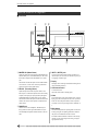
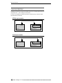
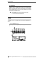
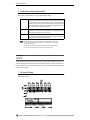
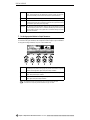
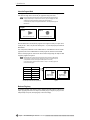
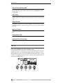
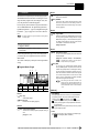
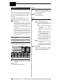
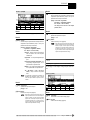
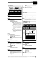
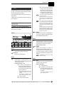
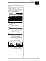
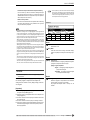
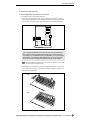
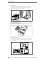
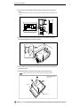
NAME PLATE LOCATION: The graphic below indicates
the location of the name plate. The model number, serial
number, power requirements, etc., are located on this plate.
You should record the model number, serial number, and the
date of purchase in the spaces provided below and retain this
manual as a permanent record of your purchase.
Rear Panel
Model
Serial No.
Purchase Date
92-469- ➀ (rear)
2
A5000/A4000 ● ● ● ● ● ● ● ● ● ● ● ● ● ● ● ● ● ● ● ● ● ● ● ● ● ● ● ● ● ● ● ● ● ● ● ● ● ● ● ● ● ● ● ● ● ● ● ● ● ● ● ● ● ● ● ● ● ● ● ● ● ● ● ● ● ● ● ● ●
PRECAUTIONS
PLEASE READ CAREFULLY BEFORE PROCEEDING
* Please keep these precautions in a safe place for future reference.
WARNING
Always follow the basic precautions listed below to avoid the possibility of serious injury or even death from electrical shock, shortcircuiting, damages, fire or other hazards. These precautions include, but are not limited to, the following:
• Do not open the instrument or attempt to disassemble the internal parts or modify
them in any way. The instrument contains no user-serviceable parts. If it should
appear to be malfunctioning, discontinue use immediately and have it inspected by
qualified Yamaha service personnel.
• Do not expose the instrument to rain, use it near water or in damp or wet conditions,
or place containers on it containing liquids which might spill into any openings.
• If the power cord or plug becomes frayed or damaged, or if there is a sudden loss of
sound during use of the instrument, or if any unusual smells or smoke should
appear to be caused by it, immediately turn off the power switch, disconnect the
electric plug from the outlet, and have the instrument inspected by qualified Yamaha
service personnel.
• Only use the voltage specified as correct for the instrument. The required voltage is
printed on the name plate of the instrument.
• Always connect the three-pin attachment plug to a property grounded power source.
(For more information about the main power supply, see “Power Connection”.)
• Before cleaning the instrument, always remove the electric plug from the outlet.
Never insert or remove an electric plug with wet hands.
• Check the electric plug periodically and remove any dirt or dust which may have
accumulated on it.
CAUTION
Always follow the basic precautions listed below to avoid the possibility of physical injury to you or others, or damage to the instrument or other property. These precautions include, but are not limited to, the following:
• Do not place the power cord near heat sources such as heaters or radiators, and do
not excessively bend or otherwise damage the cord, place heavy objects on it, or
place it in a position where anyone could walk on, trip over, or roll anything over it.
• When removing the electric plug from the instrument or an outlet, always hold the
plug itself and not the cord. Pulling by the cord can damage it.
• Do not connect the instrument to an electrical outlet using a multiple-connector.
Doing so can result in lower sound quality, or possibly cause overheating in the outlet.
• Remove the electric plug from the outlet when the instrument is not to be used for
extended periods of time, or during electrical storms.
• Before connecting the instrument to other electronic components, turn off the power
for all components. Before turning the power on or off for all components, set all
volume levels to minimum. Also, be sure to set the volumes of all components at
their minimum levels and gradually raise the volume controls while playing the
instrument to set the desired listening level.
• Do not expose the instrument to excessive dust or vibrations, or extreme cold or
heat (such as in direct sunlight, near a heater, or in a car during the day) to prevent
the possibility of panel disfiguration or damage to the internal components.
• Do not use the instrument near other electrical products such as televisions, radios,
or speakers, since this might cause interference which can affect proper operation of
the other products.
• Do not place the instrument in an unstable position where it might accidentally fall
over.
• Before moving the instrument, remove all connected cables.
• When cleaning the instrument, use a soft, dry cloth. Do not use paint thinners, solvents, cleaning fluids, or chemical-impregnated wiping cloths. Also, do not place
vinyl, plastic or rubber objects on the instrument, since this might discolor the panel
or keyboard.
• Do not rest your weight on, or place heavy objects on the instrument, and do not use
excessive force on the buttons, switches or connectors.
• Do not place objects in front of the instrument’s air vent, since this may prevent adequate ventilation of the internal components, and possibly result in the instrument
overheating. To ensure adequate ventilation and cooling, leave at least 10cm of open
space behind the A5000/A4000 rear panel, and at least 4cm of open space above the
top cover.
• Do not operate the instrument for a long period of time at a high or uncomfortable
volume level, since this can cause permanent hearing loss. If you experience any
hearing loss or ringing in the ears, consult a physician.
■ SAVING USER DATA
• To protect against data loss caused by malfunction or operating error, be sure to
save your data regularly to floppy disk, hard disk or other strage medium.
Yamaha cannot be held responsible for damage caused by improper use or modifications to the instrument, or data that is lost or destroyed.
Always turn the power off when the instrument is not in use.
■ Handling and Installation of Options
WARNING
• Before beginning installation, switch off the power to the A5000/A4000 and connected peripherals, and unplug them from the power outlet. Then remove all cables
connecting the A5000/A4000 to other devices. (Leaving the power cord connected
while working can result in electric shock. Leaving other cables connected can
interfere with work.)
• Do not disassemble, modify, or apply excessive force to board areas and connectors
on option boards, hard disk, ZIP drive, and SIMMs. Bending or tampering with
boards and connectors may lead to electric shock, fire, or equipment failures.
*
*
CAUTION
• Before handling an option board, hard disk, ZIP drive, or SIMM, you should briefly
touch the A5000/A4000 metal casing (or other such metallic area) with your bare
hand so as to drain off any static charge from your body. Note that even a slight
amount of electrostatic discharge may cause damage to these components.
• It is recommended that you wear gloves to protect your hands from metallic projections on the A5000/A4000, hard disk, SIMMs, ZIP drive, option boards, and other
components. Touching leads or connectors with bare hands may cause finger cuts,
and may also result in poor electrical contact or electrostatic damage.
• Take care to avoid dropping screws into the A5000/A4000 unit. If a screw does fall
in, be sure to remove it before you reassemble and power up the unit. Starting the
unit with a loose screw inside may lead to improper operation or equipment failure.
(If you are unable to retrieve a dropped screw, consult your Yamaha dealer for
advice.)
Consult your Yamaha dealer if you have any questions regarding installation procedures for options boards, hard disks, SIMMs, or other optional devices.
If SIMM memory, hard disk, ZIP drive, or other optional component fails to work properly, consult the item's dealer for advice.
(2)-6
●●●●●●●●●●●●●●●●●●●●●●●●●●●●●●●●●●●●●●●●●●●●●●●●●●●●●●●●●●●●●●●●●●●●
A5000/A4000
3
Thank you for your purchase of the Yamaha A5000/A4000 Professional Sampler. The
A5000/A4000 incorporates a leading-edge AWM2 tone generator, and is an ideal for use
with synthesizers, MIDI keyboards, and other MIDI devices in a wide variety of musical
applications.
This owner’s manual will help you get the most from your A5000/A4000’s many advanced
features. Please read through the essential parts of the manual carefully before beginning
work with your sampler, and refer back to the manual for additional information as necessary. Please be sure to store the manual in a safe and handy location.
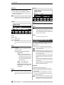
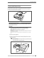
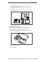
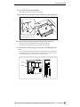
List of Accessories
Your A5000/A4000 package includes the following accessories. Make sure that all of these accessories are included.
• CD-ROM set
• Booklet (“Guide for Accompanying Disks”) ............1
• Power Cord ............................................................1
• Power Cable for Internal Hard Disk........................1
• SCSI Cable for Internal Hard Disk .........................1
Power Cord
• Owner’s Manual (this document) ................ 1
• Floppy Disk .................................................. 4
• Power Cable for ZIP Drive ........................... 1
• IDE Cable for Internal Hard Disk ................. 1
Power Cable for
Internal Hard Disk (long)
SCSI Cable for
Internal Hard Disk
Power Cable for
ZIP Drive (short)
IDE Cable for
Internal Hard Disk
* If any of the above items is missing, please contact your Yamaha dealer for assistance.
* See the CD-ROM jackets or the separate “Guide for Accompanying Disks” booklet for information about the contents and use of the CD-ROMs
and floppy disks.
Unauthorized copying of copyrighted software for purposes other than purchaser’s personal use is prohibited.
4
A5000/A4000 ● ● ● ● ● ● ● ● ● ● ● ● ● ● ● ● ● ● ● ● ● ● ● ● ● ● ● ● ● ● ● ● ● ● ● ● ● ● ● ● ● ● ● ● ● ● ● ● ● ● ● ● ● ● ● ● ● ● ● ● ● ● ● ● ● ● ● ● ●
Features
Features
Professional Sampler With Endless Potential
The A5000/A4000 provides superior sound and peformance for a wide range of applications including
break-beat production and playback, phrase sampling, musical instrument sampling, and much, much
more.
Advanced Built-in Effect System
The A5000 has 6 high-performance effect blocks, and the A4000 has 3. An extensive range of effects
from simple ambience to sophisticated sound modification can be used to enhance or radically alter the
sound of samples, break-beats, or sampled phrases. Effects can even be applied during recording, so
you can create samples with integral effects!
Fast, Efficient Operation
A large 320 x 80 dot full-graphic LCD panel displays sample waveforms, effect connections, and other
important data in easy-to-understand form. The panel knobs, mode buttons, and function buttons also
make operation exceptionally easy, intuitive, and versatile, while offering an amazing degree of realtime playback control.
Exceptional Expandability
With a built-in SCSI interface and internal SCSI and IDE connectors it’s easy to add internal hard disk
or ZIP drives, or external hard disk, ZIP, CD-ROM, CD-R or other drives. Further, 4 SIMM slots allow
the sample memory to be expanded to maximum 128 megabytes. An optional AIEB1 I/O expansion
board can be installed to provide 6 assignable analog outputs as well as digital coaxial and optical
inputs and outputs.
Compatibility with a Wide Range of Sample Formats
In addition to being able to export and import AIFF and WAV wave files to or from floppy disk, SCSI
disk, CD-ROM or other media, The A5000/A4000 can import a wide range of sample files from other
devices including the Yamaha EX7/5/5R, SU700, and samplers from other manufacturers.
A Wide Selection of Sample Data Included
The A5000/A4000 comes with the CD-ROMs packed with useful sample data and audio sampling
sources. Load the sample data directly, and record the audio source material to create your own samples. You can begin using your A5000/A4000 to make music immediately.
(An external SCSI CD-ROM drive is required to load the sample data.)
* The company names and product names in this Owner’s Manual are the trademarks or registered trademarks of
their respective companies.
●●●●●●●●●●●●●●●●●●●●●●●●●●●●●●●●●●●●●●●●●●●●●●●●●●●●●●●●●●●●●●●●●●●●
A5000/A4000
5
Using the Manual
Using the Manual
Manual Organization
This manual is divided into 10 chapters, as follows:
Chapter 1
(page 17 — 30)
Connecting the A5000/A4000 to external MIDI equipment, amplifiers, etc., and powering up. Please
read this chapter before using your A5000/A4000 for the first time.
Chapter 2
(page 31 — 56)
An easy introduction to sampling and some of the A5000/A4000’s main feature. Follow the “handson” instructions to become familiar with your A5000/A4000.
Chapter 3
(page 57 — 86)
An in-depth look at the A5000/A4000 system and basic operating procedures. Essential knowledge for
anyone who wants to make full use of the A5000/A4000’s capabilities.
Chapter 4 — Chapter 9
(page 87 — 230)
The “reference” chapters, with complete, detailed information on all of the A5000/A4000 functions
and features.
Appendix
(page 231)
Information on installing options, specifications, error messages, MIDI data format, and more.
Finding Information You Need
The manual offers several ways for you to locate specific information.
The Table of Contents
(page 8)
Look here to locate information in relatively broad categories.
The Index
(page 287)
Function names, key words, and other specific terms are listed in alphabetical order with page numbers allowing you to locate specific information quickly and easily.
Controls & Connectors
(page 10)
When you want to know about specific controls or connectors, go to this section.
The A5000/A4000 Function Tree
(page 73)
The Function Tree lets you find functions in context within the sampler’s internal organization.
6
A5000/A4000 ● ● ● ● ● ● ● ● ● ● ● ● ● ● ● ● ● ● ● ● ● ● ● ● ● ● ● ● ● ● ● ● ● ● ● ● ● ● ● ● ● ● ● ● ● ● ● ● ● ● ● ● ● ● ● ● ● ● ● ● ● ● ● ● ● ● ● ● ●
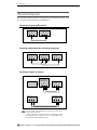
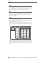
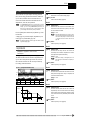
Using the Manual
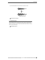
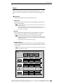
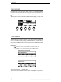
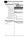
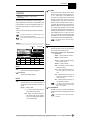
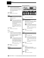
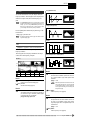
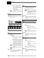
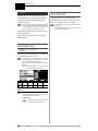
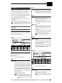
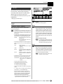
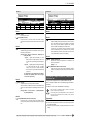
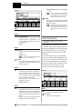
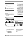
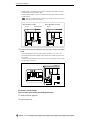
Flip Through the Pages
The chapter number and title are printed at the bottom of each manual page. The mode and function
described on each page are listed at the top of the page. Next to the mode and function names at the top
of each page is a 5 x 6 matrix which visually indicates the function described based on the mode and
function button positions as shown below.
Function Buttons
Mode Buttons
EDIT-FILTER
Other Conventions
The following symbols and conventions are used throughout this manual:
This symbol indicates important information that could, for example, prevent you from
accidentally erasing valuable data.
Additional information that will give you a more complete understanding of the related
function or feature.
Hints on how you might be able to make the most of a feature or function.
(PLAY-PROGRAM-PgmSel), etc.
This type of expression indicates the mode, function, and display page on which a certain function or parameter can be found. The example points to the PLAY mode PROGRAM function group PgmSel display page.
[PLAY], etc. Indicates a panel button — in this case the [PLAY] button.
page ??
Page reference. Directs you to another page for related information.
In general this manual describes operation of both the A5000 and A4000. When a feature or function
described is different or is not available in the A4000, this will be mentioned in the text or in parentheses
following the text.
The illustrations and LCD screens as shown in this owner’s manual are for instructional purposes only, and
may be different from your instrument.
●●●●●●●●●●●●●●●●●●●●●●●●●●●●●●●●●●●●●●●●●●●●●●●●●●●●●●●●●●●●●●●●●●●●
A5000/A4000
7
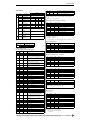
Contents
Contents
List of Accessories................................................................... 4
Features................................................................................... 5
Using the Manual..................................................................... 6
Manual Organization ............................................................... 6
Finding Information You Need.................................................. 6
Other Conventions................................................................... 7
Panel and Connector Arrangement ....................................... 10
A5000/A4000 Options ........................................................... 14
Handling the Floppy Disk Drive(FDD) and Floppy Disk ......... 15
Chapter 1 Setting Up
Setup Procedure.................................................................... 18
Power Connection.................................................................. 19
Audio Output Connections..................................................... 20
Audio Input Connections........................................................ 23
MIDI Connections .................................................................. 25
Powering On and Off ............................................................. 27
Sound Check ......................................................................... 28
Tutorial
Chapter 2 Sampler Basics & Essential
Procedures
Sampler Basics .............................................................................. 32
Essential Procedures .................................................................... 37
Chapter 3 The A5000/A4000 System & Features
1. System Overview ...................................................................... 58
Internal Structure ................................................................... 58
Sampling Tone Generator ...................................................... 59
The Effect Stage .................................................................... 63
Total EQ ................................................................................. 64
Controllers ............................................................................. 64
Sequencer ............................................................................. 64
I/O Interface ........................................................................... 65
Data Organization & Management ........................................ 65
2. The A5000/A4000 Functions .................................................... 68
A5000/A4000 Mode Organization ......................................... 68
Function Tree ......................................................................... 73
3. Basic Operation ........................................................................ 77
Common Mode Display Features .......................................... 77
Selecting Modes & Functions ................................................ 77
Selecting Display Pages ........................................................ 78
Editing Parameters ................................................................ 79
Executing Functions .............................................................. 80
Command Selection .............................................................. 80
Character Entry ..................................................................... 81
MIDI Input .............................................................................. 82
QUICK Entry.......................................................................... 83
Tree View Display .................................................................. 83
A/D Input................................................................................ 85
MIDI Indicator ........................................................................ 85
Shortcut Operation ................................................................ 86
Special Button Functions....................................................... 86
Factory Reset ........................................................................ 86
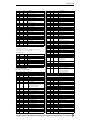
8
Reference
Chapter 4 PLAY Mode
About the PLAY Mode.................................................................... 88
1. PROGRAM ................................................................................. 89
Program Select ...................................................................... 89
Program Mix........................................................................... 90
Program Portamento.............................................................. 91
2. SAMPLE ..................................................................................... 93
Select Sample........................................................................ 93
Select Sample from Sample Bank ......................................... 95
3. EASY EDIT ................................................................................. 96
Mix ......................................................................................... 96
Output .................................................................................... 97
Out & Gain ............................................................................. 97
Filter ....................................................................................... 98
Pitch ....................................................................................... 98
Amplitude EG......................................................................... 99
Key ......................................................................................... 99
Velocity................................................................................. 100
Crossfade............................................................................. 100
Control ................................................................................. 101
4. EFFECT .................................................................................... 102
Effect Setup A ...................................................................... 102
Effect Setup B ...................................................................... 104
Effect Edit............................................................................. 104
5. SETUP ...................................................................................... 107
S/H Speed ........................................................................... 107
AD Input ............................................................................... 107
6. CONTROL ................................................................................ 110
Program Controller A/B........................................................ 110
Channel Setup ..................................................................... 112
Program LFO ....................................................................... 113
Chapter 5 EDIT Mode
About the EDIT Mode................................................................... 118
1. TRIM/LOOP .............................................................................. 120
Waveform............................................................................. 120
Sample Information.............................................................. 124
Loop Remix.......................................................................... 125
2. MAP/OUT ................................................................................. 127
Mix & Key Range ................................................................. 127
Pitch ..................................................................................... 129
Expand & Velocity Range..................................................... 131
Level Scaling........................................................................ 132
3. FILTER...................................................................................... 133
Filter & EQ ........................................................................... 133
Filter Scaling ........................................................................ 135
4. EG............................................................................................. 137
Amplitude EG....................................................................... 137
Filter EG............................................................................... 138
Pitch EG............................................................................... 140
5. LFO........................................................................................... 143
LFO ...................................................................................... 143
A5000/A4000 ● ● ● ● ● ● ● ● ● ● ● ● ● ● ● ● ● ● ● ● ● ● ● ● ● ● ● ● ● ● ● ● ● ● ● ● ● ● ● ● ● ● ● ● ● ● ● ● ● ● ● ● ● ● ● ● ● ● ● ● ● ● ● ● ● ● ● ● ●
Contents
6. MIDI/CTRL................................................................................ 145
MIDI Set............................................................................... 145
Sample Controller A & B...................................................... 146
4. MASTER................................................................................... 195
Tuning .................................................................................. 195
Output .................................................................................. 195
Chapter 6 RECORD Mode
5. SYSTEM ................................................................................... 197
KeysSet................................................................................ 197
Customise ............................................................................ 198
About the RECORD Mode ........................................................... 150
1. RECORD .................................................................................. 151
Record ................................................................................. 151
2. SETUP...................................................................................... 153
Record Setup....................................................................... 153
Process................................................................................ 157
3. TRIGGER ................................................................................. 158
Trigger.................................................................................. 158
4. EFFECT.................................................................................... 160
Recording Effect Setup........................................................ 160
Recording Effect Edit ........................................................... 160
5. EXT CTRL (External Control) ................................................. 161
CD-DA Control..................................................................... 161
6. MONITOR ................................................................................. 163
Monitor & Click..................................................................... 163
Chapter 7 DISK Mode
About the DISK Mode .................................................................. 166
1. PROGRAM ............................................................................... 167
PgmLoad ............................................................................. 167
2. SAMPLE................................................................................... 169
SmpLoad ............................................................................. 169
3. SEQUENCE.............................................................................. 171
SeqLoad .............................................................................. 171
6. MIDI .......................................................................................... 200
Channel Message ................................................................ 200
System Exclusive................................................................. 201
Chapter 9 COMMAND
About the COMMANDS................................................................ 204
Selecting a Command ......................................................... 206
Command Execution............................................................ 206
COPY................................................................................... 206
DELETE ............................................................................... 208
SAVE.................................................................................... 208
ARRANGE ........................................................................... 211
FREEZE............................................................................... 212
REGISTER .......................................................................... 214
BULK DUMP ........................................................................ 216
INITIALIZE ........................................................................... 217
PROCESS ........................................................................... 218
LOOP DIVIDE ...................................................................... 221
RESAMPLE ......................................................................... 222
STEREO → MONO ............................................................. 225
MOVE .................................................................................. 226
CREATE OSC ...................................................................... 227
EXPORT .............................................................................. 228
REVERT .............................................................................. 230
4. VOLUME................................................................................... 172
Volume................................................................................. 172
5. DISK ......................................................................................... 173
Disk Select........................................................................... 173
Disk Setup ........................................................................... 173
6. IMPORT.................................................................................... 175
Import .................................................................................. 175
7. DISK COMMANDS................................................................... 177
Selecting a Command ......................................................... 177
Command Execution ........................................................... 177
SAVE ................................................................................... 177
FORMAT .............................................................................. 177
COPY VOLUME................................................................... 181
SYSTEM FILE ..................................................................... 182
BACKUP .............................................................................. 182
CD-DA ................................................................................. 184
LOAD OS............................................................................. 185
Appendix
Installing Optional Equipment .................................................... 232
Removing the Top Cover...................................................... 232
Replacing the Top Cover...................................................... 233
Installing SIMMs .................................................................. 234
Installing the AIEB1 I/O Expansion Board ........................... 237
Installing an Internal SCSI Hard Disk .................................. 240
Installing an Internal IDE Hard Disk..................................... 244
Installing an ATAPI ZIP Drive ............................................... 247
Connecting external SCSI devices ...................................... 251
Specifications............................................................................... 254
Effect Type List ............................................................................. 256
Effect Parameter List ................................................................... 258
Control Change Number List ...................................................... 270
Troubleshooting ........................................................................... 271
Chapter 8 UTILITY Mode
Error Messages ............................................................................ 273
About the UTILITY Mode ............................................................. 188
MIDI Data Format ......................................................................... 274
1. TOTAL EQ ................................................................................ 189
Total Equalizer ..................................................................... 189
MIDI Implementation Chart ......................................................... 286
Index.............................................................................................. 287
2. PANEL PLAY............................................................................ 191
Knob Controller.................................................................... 191
Knob Controller Setup ......................................................... 191
Function Key Play Setup...................................................... 192
3. SEQUENCE.............................................................................. 194
Sequence ............................................................................ 194
●●●●●●●●●●●●●●●●●●●●●●●●●●●●●●●●●●●●●●●●●●●●●●●●●●●●●●●●●●●●●●●●●●●●
A5000/A4000
9
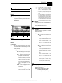
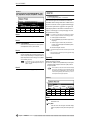
Panel and Connector Arrangement
Panel and Connector Arrangement
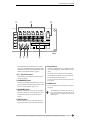
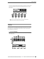
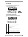
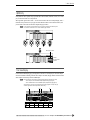
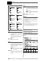
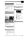
■ Front Panel
q
w y
e
r
q MASTER VOL (Master Volume)
Adjusts the volume of the signal appearing at the STEREO OUT
L/MONO and R jacks as well as the PHONES jack. This control
does not affect output from the ASSIGNABLE OUT L and R
jacks.
This knob does not affect the output level at the ASSIGNABLE
OUT connectors, or at the various connectors provided on the
optional I/O expansion board (AIEB1 board).
w REC VOL (Recording Volume)
Adjusts the input level from the front panel’s INPUT L and
INPUT R jacks. Use the knob to adjust the level when recording
a sample, or when passing an input signal directly through the
A5000/A4000 outputs for realtime output (“A/D In” feature).
This knob does not affect the input level to the DIGITAL IN and
OPTICAL IN connectors on the optional I/O expansion board
(AIEB1 board).
e PHONES jack
Connects to a set of stereo headphones. The PHONES jack
always produces the same signal as the STEREO OUT jacks.
Note that headphone impedance should be between 16 and 150
ohms.
10
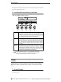
t
u
r INPUT L, INPUT R jacks
Use these jacks to input an analog signal for recording, or for
realtime output (“A/D In” feature). Use the INPUT L jack if you
are supplying a monaural signal.
t Display
The display shows a wide range of information including current
status and available parameters.
y LCD Contrast Control
LCD Contrast Control
Adjusts the contrast of the LCD display panel.
u Knobs
You use the knobs to set the various parameter values, to switch
display pages, and execute operations. In most cases you turn the
knob to set a value, and push the knob to execute an operation —
for example, to start or stop recording. Knobs are numbered 1 to
5.
i Mode buttons
The A5000/A4000 provides five operating modes. You select the
mode by pressing the corresponding mode button. The button
lamp comes on to indicate that the mode is selected.
Each mode is further divided into six functions. After selecting
the mode, you can switch among its functions by pressing the
appropriate function keys.
A5000/A4000 ● ● ● ● ● ● ● ● ● ● ● ● ● ● ● ● ● ● ● ● ● ● ● ● ● ● ● ● ● ● ● ● ● ● ● ● ● ● ● ● ● ● ● ● ● ● ● ● ● ● ● ● ● ● ● ● ● ● ● ● ● ● ● ● ● ● ● ● ●
Panel and Connector Arrangement
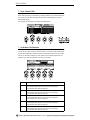
i
o
!4
A5000
!0
!1
!2
!3
(The A5000/A4000 also uses the button lamps to let you know
that it is receiving MIDI data. Each lamp corresponds to a different MIDI data type, and will continue to blink while the A5000/
A4000 is receiving MIDI data of that type. (page 85))
o [F1] — [F6] Function buttons
Use these buttons to switch among the six functions within the
currently selected mode.
!0 [COMMAND/EXIT] button
This button calls the command menu from which you can access
a range of commands not included in the modes. Press a second
time to revert to the mode display. (page 177, 206)
!3 Floppy-disk drive
Accepts a 3.5-inch floppy disk. You can use floppy disks to save
and reload your data (programs, samples, sequences, and system
settings).
Note that there is an access lamp at the lower left of the drive.
The lamp lights up while the disk is being accessed. Please do
not eject the floppy-disk while this lamp is on.
To eject a disk, press the EJECT button at the lower right of the
drive. (page 15)
!4 POWER switch
Press once to switch the power on. Press again to turn the power
off. (page 27)
!1 [ASSIGNABLE] button
This button can be used to turn off all notes, reset all controllers,
switch Knobs 2 through 5 for control change operation, switch
the function buttons for tone generator playback, and more.
(page 86)
• The A5000/A4000 stores all new data into main memory only, and
will lose all of this data when you switch off the power. You must
therefore be sure to save all important data to disk before turning
the A5000/A4000 off.
!2 [AUDITION] button
Press the button to play out the currently selected sample. You
use this feature to check the sound of the sample while editing.
●●●●●●●●●●●●●●●●●●●●●●●●●●●●●●●●●●●●●●●●●●●●●●●●●●●●●●●●●●●●●●●●●●●●
A5000/A4000
11
Panel and Connector Arrangement
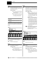
■ Rear Panel
q
t
w
e
r
A5000
q AC inlet
Connects to the AC power cord supplied with the A5000/A4000.
(Please do not use any other power cord with this unit.)
w MIDI IN-A, IN-B, OUT, THRU-A, THRU-B
(MIDI IN, OUT, THRU on the A4000)
r STEREO OUT jacks
These are the main analog output jacks.
t SCSI connector
This is a half-pitch 50-pin connector. You use it to connect up a
SCSI hard drive, CD-ROM drive, or other SCSI device.
These connectors are for connection to external MIDI devices.
The MIDI IN-A and MIDI IN-B connectors (MIDI IN only on
the A4000) are for reception of MIDI messages, while the MIDI
OUT connector is for MIDI transmission. MIDI THRU-A and
THRU-B (MIDI THRU only on the A4000) retransmits the data
received at the MIDI IN connector(s).
e ASSIGNABLE OUT jacks
Analog output jacks. These jacks operate independently of the
STEREO OUT jacks. You can use these jacks to output the
sound of one or more selected samples, or to output the signal
supplied through the front panel’s analog input connectors (page
97, 128). You may also set them so that they output the same signal as the STEREO OUT jacks (page 125).
12
A5000/A4000 ● ● ● ● ● ● ● ● ● ● ● ● ● ● ● ● ● ● ● ● ● ● ● ● ● ● ● ● ● ● ● ● ● ● ● ● ● ● ● ● ● ● ● ● ● ● ● ● ● ● ● ● ● ● ● ● ● ● ● ● ● ● ● ● ● ● ● ● ●
Panel and Connector Arrangement
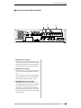
■ Rear Panel (with optional AIEB1 board installed)
q
w
e
A5000
q OPTICAL IN, OUT connectors
Use these connectors to input or output digital signals over optical-fiber cable. You can use the OPTICAL IN to record a digital
signal of frequency 48kHz, 44.1kHz, or 32kHz. The OPTICAL
OUT connector outputs a digital signal of frequency 44.1kHz.
w DIGITAL IN, OUT connectors
Use these connectors to input or output digital signals over coaxial (RCA-pin) cable. The digital signal format is CD/DAT (S/P
DIF).
You can use the DIGITAL IN connector to record a digital signal
of frequency 48kHz, 44.1kHz, or 32kHz. The DIGITAL OUT
connector outputs a digital signal of frequency 44.1kHz.
e ASSIGNABLE OUT jacks (AS1 to AS6)
Additional analog output jacks. Each pair (1&2, 3&4, 5&6)
operates independently of all other outputs on the A5000/A4000.
You can use these jacks to output the sound of one or more
selected samples, or to output the signal supplied through the
front panel’s analog input connectors (page 97, 128). You may
also set them so that they output the same signal as the STEREO
OUT jacks (page 125).
●●●●●●●●●●●●●●●●●●●●●●●●●●●●●●●●●●●●●●●●●●●●●●●●●●●●●●●●●●●●●●●●●●●●
A5000/A4000
13
A5000/A4000 Options
A5000/A4000 Options
You can enhance the capability of your A5000/A4000 by installing options. The A5000/A4000 supports
two options: (1) additional memory, and (2) the AIEB1 board (I/O expansion board).
Expansion Memory (SIMMs)
The A5000/A4000 stores all active data in main memory. To play a sample back, you must first load it into
main memory. And whenever you record a sample, you must record it into main memory.
Samples consume a great deal of memory. The A5000/A4000 comes standard with 4 megabytes (4MB) of
memory — but this is only sufficient to store about 48 seconds of high-quality monaural sound (at 44.1kHz
sampling frequency), or approximately 24 seconds of stereo sound.
You can increase this capacity by installing additional memory. The A5000/A4000 accepts expansion memory in the form of SIMMs (single in-line memory modules). Using SIMMs, you can install up to 128MB of
memory onto the A5000/A4000. SIMMs can be purchased from almost any computer-supply dealer.
Adding memory will allow you to record longer samples, and to work with more samples at the same time.
For information about how to install SIMMs, refer to the Appendix. (page 234)
Important Information about Purchase of Expansion SIMMs for the A5000/A4000
The A5000/A4000 does not necessarily support all commercially available SIMMs. Before purchasing SIMMs, please consult your Yamaha dealer or an authorized Yamaha distributor (see
list at end of the Owner’s Manual) for advice. Note that Yamaha cannot assume responsibility
for SIMM malfunctions.
SIMM Type and SIMM Configuration
• You need to use 72-pin SIMMs with access time of 70ns or less. The SIMM module size may be 4MB,
8MB, 16MB, or 32MB. The A5000/A4000 is designed for use with 32-bit (parity non-type) SIMMs, but
can also accept installation of 36-bit (parity-type) SIMMs.
• When purchasing SIMMs, make sure that the SIMM design does not utilize more than 18 memory
chips per module. (SIMMs comprised of more than 18 chips do not operate correctly on the A5000/
A4000.)
• SIMMs must be installed in pairs: you can install either two SIMMs or four SIMMs. Both modules in a
pair must have the same memory capacity.
• The A5000/A4000 ships with 4MB of sampling memory installed, and is capable of accessing up to
128MB. If you add one pair of 32MB SIMMs, for example, you increase the available sampling memory
to a total of (4 + 32 x 2 =) 68MB. If you install four 32MB SIMMs, however, the sampling memory size
becomes 128MB (and the original 4MB are effectively disabled).
• Yamaha recommends that you purchase SIMMs that conform to the JEDEC* standard. Please be
aware, however, that conformance to this standard does not constitute a guarantee that the SIMMs will
operate correctly on the A5000/A4000.
* JEDEC (Joint Electron Device Engineering Council) sets standards for terminal configurations within electronic devices.
The I/O Expansion Board (AIEB1 Board)
In its standard configuration, the A5000/A4000 supports analog I/O only. Although it stores all internal data
in digital form, it does not provide direct digital I/O connectors.
You can add digital I/O capacity by installing an AIEB1 board. The board offers two different digital connector types: optical connectors, and coaxial connectors. As an added benefit, the board also includes three
stereo ASSIGNABLE OUTPUT pairs (six analog jacks), which operate independently of the standard STEREO OUT and ASSIGNABLE OUT jacks.
For information about how to install this board, refer to the Appendix. (page 237)
14
A5000/A4000 ● ● ● ● ● ● ● ● ● ● ● ● ● ● ● ● ● ● ● ● ● ● ● ● ● ● ● ● ● ● ● ● ● ● ● ● ● ● ● ● ● ● ● ● ● ● ● ● ● ● ● ● ● ● ● ● ● ● ● ● ● ● ● ● ● ● ● ● ●
Handling the Floppy Disk Drive(FDD) and Floppy Disk
Handling the Floppy Disk Drive(FDD) and Floppy Disk
Precautions
Be sure to handle floppy disks and treat the disk drive with care. Follow the important precautions below.
Disk Type
The A5000/A4000 disk drive accepts 2HD-type and 2DD-type 3.5" floppy disks.
Inserting/Ejecting Floppy Disks
To insert a floppy disk into the disk drive:
• Hold the disk so that the label of the disk is facing upward and the sliding shutter is facing forward,
towards the disk slot. Carefully insert the disk into the slot, slowly pushing it all the way in until it
clicks into place and the eject button pops out.
To eject a floppy disk:
• Before ejecting the disk, be sure to confirm that the FDD is stopped (check if the LED below the
floppy disk slot is off).
Press the eject button slowly as far as it will go; the disk will automatically pop out. When the disk
is fully ejected, carefully remove it by hand.
• Never attempt to remove the disk or turn the power off during reading or writing. Doing so can
damage the disk and possibly the disk drive.
• If the eject button is pressed too quickly, or if it is not pressed in as far as it will go, the disk may
not eject properly. The eject button may become stuck in a half-pressed position with the disk
extending from the drive slot by only a few millimeters. If this happens, do not attempt to pull out
the partially ejected disk, since using force in this situation can damage the disk drive mechanism
or the floppy disk. To remove a partially ejected disk, try pressing the eject button once again, or
push the disk back into the slot and then repeat the eject procedure.
• Be sure to remove the floppy disk from the disk drive before turning off the power. A floppy disk
left in the drive for extended periods can easily pick up dust and dirt that can cause data read and
write errors.
●●●●●●●●●●●●●●●●●●●●●●●●●●●●●●●●●●●●●●●●●●●●●●●●●●●●●●●●●●●●●●●●●●●●
A5000/A4000
15
Handling the Floppy Disk Drive(FDD) and Floppy Disk
Cleaning the Disk Drive Read/Write Head
• Clean the read/write head regularly. This instrument employs a precision magnetic read/write head
which, after an extended period of use, will pick up a layer of magnetic particles from the disks
used that will eventually cause read and write errors.
• To maintain the disk drive in optimum working order Yamaha recommends that you use a commercially-available dry-type head cleaning disk to clean the head about once a month. Ask your
Yamaha dealer about the availability of proper head-cleaning disks.
Never insert anything but floppy disks into the disk drive. Other objects may cause damage to the disk drive
or floppy disks.
About the Floppy Disks
To handle floppy disks with care:
• Do not place heavy objects on a disk or bend or apply pressure to the disk in any way. Always keep
floppy disks in their protective cases when they are not in use.
• Do not expose the disk to direct sunlight, extremely high or low temperatures, or excessive humidity, dust or liquids.
• Do not open the sliding shutter and touch the exposed surface of the floppy disk inside.
• Do not expose the disk to magnetic fields, such as those produced by televisions, speakers, motors,
etc., since magnetic fields can partially or completely erase data on the disk, rendering it unreadable.
• Never use a floppy disk with a deformed shutter or housing.
• Do not attach anything other than the provided labels to a floppy disk. Also make sure that labels
are attached in the proper location.
To protect your data (Write-protect Tab):
• To prevent accidental erasure of important data, slide the disk’s write-protect tab to the “protect”
position (tab open).
Data backup
• For maximum data security Yamaha recommends that you keep two copies of important data on
separate floppy disks. This gives you a backup if one disk is lost or damaged.
16
A5000/A4000 ● ● ● ● ● ● ● ● ● ● ● ● ● ● ● ● ● ● ● ● ● ● ● ● ● ● ● ● ● ● ● ● ● ● ● ● ● ● ● ● ● ● ● ● ● ● ● ● ● ● ● ● ● ● ● ● ● ● ● ● ● ● ● ● ● ● ● ● ●
Chapter
1
Setting Up
Connecting the A5000/A4000 to external MIDI equipment, amplifiers, etc., and powering up. Please read this chapter before using your A5000/A4000 for the first time.
Setup Procedure ...........................................................................18
Power Connection ........................................................................19
Audio Output Connections ..........................................................20
Audio Input Connections .............................................................23
MIDI Connections .........................................................................25
Powering On and Off ....................................................................27
Sound Check.................................................................................28
● ● ● ● ● ● ● ● ● ● ● ● ● ● ● ● ● ● ● ● ● ● ● ● ● ● ● ● ● ● ● ● ● ● ● ● ● ● ● ● ● ● ● ● ● ● ● ● ● ● ● ● ● ● ● A5000/A4000 •
Chapter 1 Setting Up
17
Setup Procedure
Setup Procedure
his chapter explains how to set up your equipment and run a simple sound check.
Setup Sequence
This chapter takes you through each of the steps necessary to connect up your system.
Connecting the Power
Explains how to connect up the A5000/A4000’s power cord. (page 19)
Connecting the A5000/A4000 Outputs
Shows how to connect the A5000/A4000’s stereo and assignable outputs to external audio devices.
(page 20)
Connecting the Audio Inputs
Shows how to connect microphones and other input devices to the A5000/A4000. (page 23)
MIDI Connections
Introduces basic MIDI concepts, and shows how to connect up MIDI devices. (page 25)
Power ON/OFF
Explains the proper sequence for turning connected devices on and off. (page 27)
Sound Check
Takes you through a simple sound check, to confirm that your equipment is connected correctly. (page
28)
• If you have already acquired and intend to install options such as addition SIMM memory, the
optional AIEB1 I/O Expansion Board, internal hard disk or ZIP disk drives, or external SCSI
devices, please install the options before carrying out the setup procedures described in this
chapter.
• SIMM (expansion memory) installation.....page 234
• AIEB1 I/O Expansion Board installation....page 237
• Internal SCSI hard disk installation ...........page 240
• Internal IDE hard disk installation .............page 244
• ATAPI ZIP drive installation .......................page 247
• External SCSI device connection..............page 251
18
Chapter 1 Setting Up • A5000/A4000 ● ● ● ● ● ● ● ● ● ● ● ● ● ● ● ● ● ● ● ● ● ● ● ● ● ● ● ● ● ● ● ● ● ● ● ● ● ● ● ● ● ● ● ● ● ● ● ● ● ● ● ● ● ● ● ●
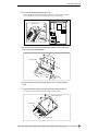
Power Connection
Power Connection
This page shows you how to connect up the power cord that comes with the A5000/A4000.
• Be sure that the A5000/A4000’s power switch is OFF before you attach the cord. (The switch is
OFF when it is all the way out.)
• The A5000/A4000 is designed for use with a grounded line (three-prong outlet).
Connecting the Cord
Connect the supplied power cord to the AC inlet on the rear panel. Then plug the other end of the cord into
a 3-prong wall outlet.
Wall Outlet
Rear Panel
AC INLET
Power Cord
WARNING
• Make sure your A5000/A4000 is rated for the AC voltage supplied in the area in which it is to be used (as
listed on the rear panel). Connecting the unit to the wrong AC supply can cause serious damage to the
internal circuitry and may even pose a shock hazard!
• Use only the AC power cord supplied with the A5000/A4000. If the supplied cord is lost or damaged and
needs to be replaced, contact your Yamaha dealer. The use of an inappropriate replacement can pose a fire
and shock hazard!
• The type of AC power cord provided with the A5000/A4000 may be different depending on the country in
which it is purchased (a third prong may be provided for grounding purposes). Improper connection of the
grounding conductor can create the risk of electrical shock. Do NOT modify the plug provided with the
A5000/A4000. If the plug will not fit the outlet, have a proper outlet installed by a qualified electrician. Do
not use a plug adaptor which defeats the grounding conductor.
● ● ● ● ● ● ● ● ● ● ● ● ● ● ● ● ● ● ● ● ● ● ● ● ● ● ● ● ● ● ● ● ● ● ● ● ● ● ● ● ● ● ● ● ● ● ● ● ● ● ● ● ● ● ● A5000/A4000 •
Chapter 1 Setting Up
19
Audio Output Connections
Audio Output Connections
This section explains how to connect the A5000/A4000 audio outputs to external devices.
• Be sure that power to the A5000/A4000 and to peripheral devices is OFF before making these
connections. Connecting devices while power is ON may result in damage to amps or speakers.
• Digital I/O connections are available only if the optional AIEB1 board is installed.
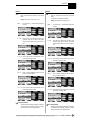
Connecting the Analog Outputs
The A5000/A4000 comes standard with the following stereo output jacks.
• STEREO OUT ...............Main analog output.
• ASSIGNABLE OUT.......You can set the jacks to operate independently of the STEREO OUT jacks, so
that they output selected samples or programs only. The feature is useful, for
example, when you want to send the main signal to one audio device while
sending a specific sample to a different device. But it is also possible to set these
jacks so that they output the same signal as the STEREO OUT jacks. (page
195)
If you have installed the optional I/O expansion board (AIEB1 board), your A5000/A4000 will include
three additional ASSIGNABLE OUT pairs (ASSIGNABLE OUT jacks 1 to 6).
For monaural output:
A5000/A4000 Rear Panel
ASSIGNABLE OUT
R
L
Amp, mixer, etc.
STEREO OUT
R L/MONO
INPUT
For stereo output:
A5000/A4000 Rear Panel
ASSIGNABLE OUT
R
L
20
Amp, mixer, etc.
STEREO OUT
R L/MONO
INPUT
L
R
Chapter 1 Setting Up • A5000/A4000 ● ● ● ● ● ● ● ● ● ● ● ● ● ● ● ● ● ● ● ● ● ● ● ● ● ● ● ● ● ● ● ● ● ● ● ● ● ● ● ● ● ● ● ● ● ● ● ● ● ● ● ● ● ● ● ●
Audio Output Connections
For assignable output:
A5000/A4000 Rear Panel
ASSIGNABLE OUT
R
L
Amp, mixer, etc.
INPUT 1
L
R
STEREO OUT
R L/MONO
INPUT 2
L
R
Assignable output using AIEB1 expansion board:
A5000/A4000
Rear Panel
6
5
4
3
2
ASSIGNABLE OUT
ASSIGNABLE OUT
R
L
1
STEREO OUT
R L/MONO
Amp, mixer, etc.
L
R
INPUT 3
L
R
INPUT 4
INPUT 1
L
R
INPUT 2
L
R
L
R
INPUT 5
(It is not necessary, of course, to connect up all of the outputs on the expansion board. Connect only
the outputs you need to use.)
● ● ● ● ● ● ● ● ● ● ● ● ● ● ● ● ● ● ● ● ● ● ● ● ● ● ● ● ● ● ● ● ● ● ● ● ● ● ● ● ● ● ● ● ● ● ● ● ● ● ● ● ● ● ● A5000/A4000 •
Chapter 1 Setting Up
21
Audio Output Connections
Connecting the Digital Outputs
You can add digital I/O capacity to the A5000/A4000 by installing the optional I/O expansion board
(AIEB1 board). The board enables direct digital output of A5000/A4000 playback and digital through-put.
For purposes of compatibility, the AIEB1 board includes two different output types: OPTICAL OUT (optical fiber) and DIGITAL OUT (coaxial cable). Note that both of these outputs always produce identical signals.
The digital outputs function as assignable outputs. You can set them to output selected samples or programs, or you can set them to produce the same output as the STEREO OUT jacks (by setting the Stereo
Out to Assignable Out parameter to DIG&OPT (UTILITY-MASTER-Out put) : page 195).
• The OPTICAL connectors are protected by plastic covers. You must remove the cover before connecting the cable. Please remember to replace the cover when you disconnect the cable.
OPTICAL output connection
IN
OUT
OPTICAL
IN
OUT
DIGITAL
A5000/A4000 Rear Panel
OPTICAL INPUT
Digital device
Coaxial output connection
IN
OUT
OPTICAL
A5000/A4000 Rear Panel
22
IN
OUT
DIGITAL
DIGITAL INPUT
Digital device
Chapter 1 Setting Up • A5000/A4000 ● ● ● ● ● ● ● ● ● ● ● ● ● ● ● ● ● ● ● ● ● ● ● ● ● ● ● ● ● ● ● ● ● ● ● ● ● ● ● ● ● ● ● ● ● ● ● ● ● ● ● ● ● ● ● ●
Audio Input Connections
Audio Input Connections
This section explains how to connect the A5000/A4000 to a microphone, cassette recorder, or other sound
source.
• Be sure that power to the A5000/A4000 and to peripheral devices is OFF before making these
connections. Connecting devices while power is ON may result in damage to amps or speakers.
• Digital I/O connections are available only if the optional AIEB1 board is installed.
• To select the input to be used for recording, use the Input parameter on the RecData page (page
155).
Connecting to Analog Input
The following illustrations show how to connect to an analog input source, such as a microphone, analog
tape recorder, or analog synthesizer.
For monaural input
Microphone, etc.
A5000/A4000 Front Panel
INPUT
L
R
Connect to INPUT L
Tape, recorder, synth, etc.
OUTPUT
A5000/A4000 Front Panel
INPUT
L
R
Connect to INPUT L
For stereo input
Microphone, etc.
A5000/A4000 Front Panel
INPUT
L
R
Tape, recorder, synth, etc.
OUTPUT
L
R
A5000/A4000 Front Panel
INPUT
L
R
● ● ● ● ● ● ● ● ● ● ● ● ● ● ● ● ● ● ● ● ● ● ● ● ● ● ● ● ● ● ● ● ● ● ● ● ● ● ● ● ● ● ● ● ● ● ● ● ● ● ● ● ● ● ● A5000/A4000 •
Chapter 1 Setting Up
23
Audio Input Connections
Connecting to Digital Input
Installation of the optional I/O expansion board (AIEB1 board) lets you record digital signals directly from
a digital input source — such as a CD player or DAT recorder.
For purposes of compatibility, the AIEB1 board includes two different input types: OPTICAL (optical
fiber) and DIGITAL (coaxial cable).
OPTICAL input connection
OPTICAL OUTPUT
Digital device
IN
OUT
OPTICAL
IN
OUT
DIGITAL
A5000/A4000 Rear Panel
Coaxial input connection
DIGITAL OUTPUT
Digital device
24
IN
OUT
OPTICAL
IN
OUT
DIGITAL
A5000/A4000 Rear Panel
Chapter 1 Setting Up • A5000/A4000 ● ● ● ● ● ● ● ● ● ● ● ● ● ● ● ● ● ● ● ● ● ● ● ● ● ● ● ● ● ● ● ● ● ● ● ● ● ● ● ● ● ● ● ● ● ● ● ● ● ● ● ● ● ● ● ●
MIDI Connections
MIDI Connections
This section explains how to connect the A5000/A4000 to MIDI devices.
• Be sure that power to the A5000/A4000 and to peripheral devices is OFF before making MIDI connections. Connecting devices while power is ON may result in MIDI processing errors or unexpected and continuous sound output.
About MIDI
The following overview introduces some basic MIDI concepts. Readers familiar with MIDI may wish to
skip to “MIDI Connection Configurations,” on the next page.
What is MIDI?
MIDI (for “Musical Instrument Digital Interface”) is a standard, internationally-recognized interface
for music-related digital communication among electronic instruments, computers, sequencers, and
related devices.
MIDI connectors and cables
MIDI devices provide MIDI connectors marked IN, OUT, and THRU. The IN connector receives data
from external devices, the OUT connector outputs locally produced data, and the THRU connector
relays data received at the IN connector. MIDI connections are made by running standard MIDI cables
between connectors on different devices. Each MIDI cable connects the OUT or THRU connector of
one device to the IN connector of another device.
Channels
A single MIDI cable carries up to 16 channels of performance data. If you have a MIDI setup consisting of three keyboards outputting performance data to a fourth device, for example, each keyboard
would be transmitting data over a different channel. Each channel is identified by its channel number
(1 to 16).
Data types
Each channel can carry a variety of data types. Data types include the following.
Note data:
Control change:
Program change:
Aftertouch:
Pitchbend:
Bulk data:
Keys (on keyboard), and key striking force
Controller movement (modulation wheel, foot controller, etc.)
Change in voice or program
Pressure applied to key after initial strike
Movement of the pitchbend wheel
Voice and device settings and related data
● ● ● ● ● ● ● ● ● ● ● ● ● ● ● ● ● ● ● ● ● ● ● ● ● ● ● ● ● ● ● ● ● ● ● ● ● ● ● ● ● ● ● ● ● ● ● ● ● ● ● ● ● ● ● A5000/A4000 •
Chapter 1 Setting Up
25
MIDI Connections
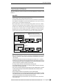
MIDI Connection Configurations
You can use MIDI connections to control the A5000/A4000 from an external keyboard, sequencer, or computer, or to transfer A5000/A4000 data to an external MIDI device.
Connecting to keyboard or MIDI controller
Keyboard (or controller)
MIDI
THRU OUT
IN
A5000/A4000 Rear Panel
MIDI
THRU OUT
IN
Connecting to keyboard/controller and external tone generator
Keyboard (or controller)
MIDI
THRU OUT
IN
A5000/A4000 Rear Panel
MIDI
THRU OUT
IN
Tone Generator (synthesizer, etc.)
MIDI
THRU OUT
IN
Connecting to computer or sequencer
MIDI Interface
(or tone generator
with built-in interface)
Computer
MIDI
THRU OUT
Sequencer
MIDI
THRU OUT
IN
A5000/A4000 Rear Panel
MIDI
THRU OUT
IN
A5000/A4000 Rear Panel
IN
MIDI
THRU OUT
IN
• A wide variety of MIDI connection configurations are available. Design your setup to suit your
device and performance requirements.
• The A5000 has MIDI THRU-A and MIDI THRU-B connectors. The MIDI THRU-A connector
retransmits MIDI data received via the MIDI IN-A connector, and the MIDI THRU-B connector
retransmits MIDI data received via the MIDI IN-B connector.
26
Chapter 1 Setting Up • A5000/A4000 ● ● ● ● ● ● ● ● ● ● ● ● ● ● ● ● ● ● ● ● ● ● ● ● ● ● ● ● ● ● ● ● ● ● ● ● ● ● ● ● ● ● ● ● ● ● ● ● ● ● ● ● ● ● ● ●
Powering On and Off
Powering On and Off
This section explains the correct procedures for powering up and powering down your equipment.
Power ON
• Speakers or amplifiers should be switched on last to protect against unexpected sound surges
that may damage your equipment.
[Procedure]
1. Switch on power to external MIDI and SCSI devices.
• When powering up MIDI devices, it is generally good practice (although not strictly necessary) to switch
on the transmitting-side device first.
• If you are switching on a SCSI disk or CD-ROM drive, allow the drive a few seconds to get up to speed
before proceeding to Step 2.
2. Switch on the power to the A5000/A4000. (Press the POWER switch on the front panel.)
3. Switch on power to speakers and other audio devices.
Power OFF
• Like other samplers, the A5000/A4000 stores all new data into main memory only, and will lose all
of this data when you switch off the power. You must therefore save all important data to disk
before turning the A5000/A4000 off.
• Speakers or amplifiers should be switched off first to protect against unexpected sound surges
that may damage your equipment.
[Procedure]
1. Switch off the amplifiers or speakers.
2. Switch off the power to the A5000/A4000. (Press the POWER switch on the front panel.)
3. Switch off external MIDI and SCSI devices.
● ● ● ● ● ● ● ● ● ● ● ● ● ● ● ● ● ● ● ● ● ● ● ● ● ● ● ● ● ● ● ● ● ● ● ● ● ● ● ● ● ● ● ● ● ● ● ● ● ● ● ● ● ● ● A5000/A4000 •
Chapter 1 Setting Up
27
Sound Check
Sound Check
The next procedure takes you though a simple sound check that you can use to confirm proper connection
of external audio and MIDI devices. The procedure assumes that you are using a MIDI keyboard to control
A5000/A4000 playback.
[Procedure]
1. Make sure that the A5000/A4000 STEREO OUT jacks are connected to an amplifier or
mixer and that all components are ready for playback. (page 20)
2. Connect the MIDI OUT connector of your MIDI controller — keyboard, sequencer, etc.
— to the MIDI IN-A connector (MIDI IN on the A4000) of the sampler and ensure that all
components are ready for MIDI control. (page 25)
3. Turn on the A5000/A40000 and all connected equipment. (page 27)
4. Set the A5000/A4000 MASTER VOL control to about the center of its range.
5. Set the amplifier, mixer, or other audio reproduction device’s volume to an appropriate
level.
6. Set the external MIDI controller’s MIDI transmit channel to 1.
7. Make sure the sampler’s [PLAY] mode button is lit (press the [PLAY] button if it isn’t).
8. Press the [F2] function button.
28
Chapter 1 Setting Up • A5000/A4000 ● ● ● ● ● ● ● ● ● ● ● ● ● ● ● ● ● ● ● ● ● ● ● ● ● ● ● ● ● ● ● ● ● ● ● ● ● ● ● ● ● ● ● ● ● ● ● ● ● ● ● ● ● ● ● ●
Sound Check
9. Rotate Knob 1 to select the Sample Select (PLAY-SAMPLE-SmpSel) display.
10. Rotate Knob 2 to highlight “sine wave,” and rotate Knob 4 to set the Receive Channel
Assign parameter to “A01” (“01” on the A4000).
• When the A5000/A4000 is turned on a number of basic-waveform samples are automatically created. In
this case we have selected the “sine wave” sample for our sound check.
11. Play the MIDI keyboard or other controller connected to the A5000/A4000.
• If you hear the sine wave sample at this point, all is OK.
• If no sound is produced, try pressing the front-panel [AUDITION] button. If pressing
the [AUDITION] button produces sound it is likely that you have not made the right
MIDI connectors or properly set your MIDI controller. If pressing the [AUDITION]
button produces no sound you should recheck your audio output connections and audio
gear. Turn the power off and go back to the previous section to check you connections
and settings.
• If the sound check is successful, continue with the following steps.
12. Turn down all audio volume controls.
13. Turn the A5000/A4000 MASTER VOL all the way to the left (minimum volume).
14. Turn off the power to the A5000/A4000 and all connected equipment.
• This completes the sound check procedure.
That completes the initial setup and test procedures. In Chapter 2 we’ll provide an easy introduction to sampling and some of the A5000/A4000’s main feature. Follow the “hands-on”
instructions to become familiar with recording and playing samples with your A5000/A4000.
● ● ● ● ● ● ● ● ● ● ● ● ● ● ● ● ● ● ● ● ● ● ● ● ● ● ● ● ● ● ● ● ● ● ● ● ● ● ● ● ● ● ● ● ● ● ● ● ● ● ● ● ● ● ● A5000/A4000 •
Chapter 1 Setting Up
29
Sound Check
30
Chapter 1 Setting Up • A5000/A4000 ● ● ● ● ● ● ● ● ● ● ● ● ● ● ● ● ● ● ● ● ● ● ● ● ● ● ● ● ● ● ● ● ● ● ● ● ● ● ● ● ● ● ● ● ● ● ● ● ● ● ● ● ● ● ● ●
Chapter
2
Sampler Basics &
Essential Procedures
Although your individual musical needs will ultimately determine how you use your
sampler, the basic operations and procedures are pretty much universal. This chapter describes the basic steps you’ll need to be familiar with for just about any sampling/playback project, and provides step-by-step procedures for some of the most
important operations.
SAMPLER BASICS........................................................................32
ESSENTIAL PROCEDURES .........................................................37
●●●●●●●●●●●●●●●●●●●●●●●●●●●●●●●●●●●●●
A5000/A4000 •
Chapter 2 Sampler Basics & Essential Procedures
31
SAMPLER BASICS
SAMPLER BASICS
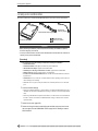
The process of using a sampler can be roughly divided into three phases:
1. Recording/Loading — getting sound into the machine.
2. Editing — Tidying up and modifying the sound as desired.
3. Playback — Putting it all together and making music.
These phases and the operations each involves are described in more detail below.
Phase 1:
RECORDING
Getting Sounds Into Your Sampler
No matter how you intend to use your sampler, the first thing you’ll need to do is to record or load the
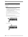
sounds you want to play into the sampler’s memory. There are basically three ways to do this:
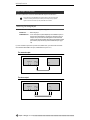
LINE RECORDING FROM
CD, DAT, TAPE, ETC.
MICROPHONE RECORDING
FROM LIVE SOURCES
SAMPLE DATA FROM
DISK OR OTHER EQUIPMENT
A5000/A4000
1.
Live Sources (Microphone Recording)
This is the method you’ll use if you will be recording acoustic musical instruments, voice, or other
“live” sound to be edited, processed, and played via the A5000/A4000.
Step-by-Step procedure on page 37.
2.
Pre-recorded Audio Sources (Line Recording)
Line recording can be used to record samples from audio CD “TOOLS,” loops and breakbeats from
appropriate CDs, of from tape, DAT, or MiniDisc audio recordings you’ve made yourself “on location.”
Step-by-Step procedure on page 37.
3.
Loading Sample Data
This procedure does not exactly qualify as “recording” since it is used to load sample data (i.e. samples already recorded and saved in digital sample format) from the internal floppy disk drive, external
hard disk or other high-capacity drives, or directly from a computer or other compatible device via the
SCSI interface.
Details beginning on page 165.
32
Chapter 2 Sampler Basics & Essential Procedures • A5000/A4000
●●●●●●●●●●●●●●●●●●●●●●●●●●●●●●●●●●●●●●
SAMPLER BASICS
Phase 2:
EDITING
Making Your Samples Sound Right
Once the sample(s) you intend to use have been satisfactorily recorded and placed in the sampler’s memory,
then you can edit the sample data to create exactly the sound you want. This can involve anything from simply trimming/looping and mapping the sample (procedures which do not actually change the sound of the
sample), to applying filter, envelope generator, low-frequency modulation, and effects which might dramatically alter the basic timbre and sound of the sample.
Although you probably won’t need to use all of the available editing functions for every sample, the normal
sequence of editing procedures would be:
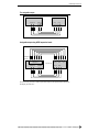
1.
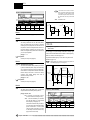
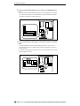
Trimming and/or Looping
Once you’ve recorded a sample you might find that there’s unnecessary space or noise preceding or
following the sound you want to use. Or you might only want to use a portion of the sound you initially recorded. Trimming, as the term implies, allows you to “trim” away unwanted portions of the
recorded sound, leaving only the sound you want to use.
TRIM
ORIGINAL
SAMPLE
TRIMMED
SAMPLE
Step-by-Step procedure on page 42.
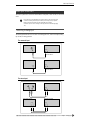
If you simply want your sample to play back in linear fashion from beginning to end, then looping is
not necessary. But if you want the entire sample to repeat continuously, or you want a specified segment of the sample to repeat continuously to create a sustained tone, then you will need to specify the
appropriate looping parameters.
STRAIGHT PLAYBACK
(NO LOOP)
The sample plays from beginning to end
(or until the note is released).
LOOPED PLAYBACK
(ONE EXAMPLE)
LOOP
In this example the specified loop repeats until the
note is released, then the final decay portion of the
sample plays. There are other types of loops.
Step-by-Step procedure on page 44.
●●●●●●●●●●●●●●●●●●●●●●●●●●●●●●●●●●●●●
A5000/A4000 •
Chapter 2 Sampler Basics & Essential Procedures
33
SAMPLER BASICS
2.
Mapping
Mapping determines the range of notes on the keyboard or other controller that will play the sample,
and how the sample will respond to those notes - e.g. whether it will always play at the same pitch or at
different pitches corresponding to the notes played. You can, for example, have a single sample played
across the entire note range, several split or overlapping samples played in different note ranges, or
many samples each played by an individual key/note.
SAMPLE 1
SAMPLE 2
SAMPLE 3
MAPPING
Step-by-Step procedure on page 46.
3.
Filter, EG, and LFO
If you want to actually modify the sound of your samples to create a desired musical effect, you might
want to apply:
• Static or dynamic velocity-controlled filtering to modify the timbre of the sound or created “wahwah” type effects.
Filter cutoff (or center) frequency
controlled by note velocity,
envelope generator or LFO.
FILTER
Step-by-Step procedure on page 47.
• Envelope-generator-based amplitude, filter, or pitch variations such that the controlled parameter
varies over time whenever a note is played.
EG
ENVELOPE
Envelope generators can produce time-based
variations in amplitude, filter frecuency or pitch.
Step-by-Step procedure on page 50.
34
Chapter 2 Sampler Basics & Essential Procedures • A5000/A4000
●●●●●●●●●●●●●●●●●●●●●●●●●●●●●●●●●●●●●●
SAMPLER BASICS
• Cyclic LFO-based amplitude, filter, or pitch variations such as tremolo or vibrato.
LFO
LFO modulation can produce cyclic variations
in amplitude, filter frecuency or pitch.
Step-by-Step procedure on page 52.
4.
Other Edit Functions
The A5000/A4000 actually offers many more editable functions than the few listed above. You can, for
example, individually set the level, pan position, pitch, velocity response, level scaling, and other
parameters for each sample. It may seem complex at first, but all these options allow you to create precisely the sound your music requires.
Details beginning on page 117.
●●●●●●●●●●●●●●●●●●●●●●●●●●●●●●●●●●●●●
A5000/A4000 •
Chapter 2 Sampler Basics & Essential Procedures
35
SAMPLER BASICS
Phase 3:
PLAYBACK
Putting It All Together & Making Music
Your individual samples are the basic “building blocks” used by the A5000 and A4000 to create musical
sound. After your samples have been recorded and edited there are still a few steps you’ll need to take
before you can start making music.
1.
Programs
Since the A5000/A4000 does not directly play individual samples, your samples need to be assigned to
a “Program” which can be played from your keyboard, computer, or other MIDI controller. A Program
can consist of a single sample played over the entire range of your keyboard or controller, or a number
of samples “mapped” to different key ranges. Another program feature offered by the A5000/A4000 is
the "Multi" mode in which different programs can be assigned up to 32 "parts" on the A5000 or up to
16 parts on the A4000, which can be played simultaneously via separate MIDI channels.
Step-by-Step procedure on page 55.
2.
Effects
The extensive range of top-quality effects provided by the A5000/A4000 can be used to add the finishing touches to your sound. Both models offer multiple effect stages with versatile connection variations. The A5000 features six high-performance effect stages, and the A4000 has three. Both samplers
offer a selection of 46 top-quality effects ranging from basic reverb, delay, and modulation effects to
much more sophisticated, innovative effects as well as combinations.
Details beginning on page 102.
3.
Controller Functions
Another basic but important step in setting up for playback is assigning controller functions. Your keyboard’s modulation wheel, for example, can be assigned to a wide range of parameters other than simple modulation. Effective use of MIDI controllers can give you extraordinary realtime expression
control.
Details beginning on page 110.
36
Chapter 2 Sampler Basics & Essential Procedures • A5000/A4000
●●●●●●●●●●●●●●●●●●●●●●●●●●●●●●●●●●●●●●
ESSENTIAL PROCEDURES
ESSENTIAL PROCEDURES
This section provides step-by-step procedures for some of the most important A5000/A4000 sampling,
editing, and playback operations. Although complete coverage of all possible procedures and variations is
not possible within the scope of this manual, the procedures provided will help you to become familiar with
the A5000/A4000 interface to the point that you should be able to achieve the desired results by referring to
the detailed “Reference” section of the manual (beginning on page 87).
• Make sure that you have properly connected and set up your A5000/A4000 as described in the
Setting Up section (page 17) before attempting the procedures in this section.
Step-by-Step
MICROPHONE/LINE RECORDING
This section describes recording from a microphone or line source. For details on loading sample data from
a floppy disk or other storage device, refer to page 165 in the reference section of this manual.
1.
Connect a Source
If you will be recording via microphone, connect a microphone with a 1/4” phone plug connector (or
use an appropriate adaptor) to the sampler’s “L” INPUT.
• Just about any high-quality dynamic or condenser microphone can be used, but the A5000/A4000
does not provide phantom power for studio-type phantom-powered condenser microphones.
• Two microphones connected to the “L” and “R” inputs, or a stereo microphone with independent 1/
4” phone plugs for the left and right channels, can be used with the A5000/A4000 to record stereo
samples.
If you will be recording from a line source, connect it to the “L,” or “L” and “R” INPUT jacks.
• If your source has either coaxial or optical digital output and you have installed the optional AIEB1
I/O Expansion Board in your sampler (page 13, 14), you can connect the digital output from your
source directly to either the coaxial SPDIF or optical input on the expansion board.
2.
Go To the Record Setup Display
Press the [REC] mode button, and then the [SETUP] function key to go to the “REC-RecSetup” display.
●●●●●●●●●●●●●●●●●●●●●●●●●●●●●●●●●●●●●
A5000/A4000 •
Chapter 2 Sampler Basics & Essential Procedures
37
ESSENTIAL PROCEDURES
3.
Select a Record Type
With the topmost function line on the display highlighted (use Knob 1 to select the top line if it is not
already selected), use Knob 2 to select the “New” Record Type. This is the Record Type to select when
you want to record a new sample to the sampler’s memory.
• In addition to “New,” you can select “New+” to append the recorded data to the end of the currently
selected sample, “Replc” to replace a specified existing sample, or “Save” to automatically save
the recorded data to disk. See page 153 for details.
4.
Select an Input
Use Knob 1 to highlight the third function line on the display, then use Knob 2 to select the input to
which your source is selected. If you have connected a mono microphone to the “L” input, for example, use Knob 2 to select “AD L”. If you have a stereo microphone or line source connected to the “L”
and “R” inputs, select “AD L/R”.
• If you have installed the optional AIEB1 I/O Expansion Board (page 13, 14), you will also be able
to select “DIGITAL” (the coaxial SPDIF digital input on the expansion board, or “OPTICAL” (the
optical digital input on the expansion board).
• The A5000/A4000 also allows you to select “StOut” in order to directly re-sample the output signal
from the sampler’s stereo outputs.
38
Chapter 2 Sampler Basics & Essential Procedures • A5000/A4000
●●●●●●●●●●●●●●●●●●●●●●●●●●●●●●●●●●●●●●
ESSENTIAL PROCEDURES
5.
Select a Sample Type
With the third function line still highlighted, use Knob 3 to select “Mono” if you want to record a
mono sample, or “Stereo” to record a stereo sample. If “Mono” is selected, a mono sample will be
recorded even if you are recording from a stereo source.
• If the optional AIEB1 I/O Expansion Board is installed (page 13, 14), and the “DIGITAL” or “OPTICAL” input is selected (above), only the “Stereo” Sample Type is available.
6.
Select a Sampling Frequency
With the third function line highlighted, use Knob 4 to select the desired sampling frequency. The
choices for the “AD L” and “AD L/R” input settings are:
44.1k
This is the same sampling frequency used by audio CDs, and the sampling frequency that
will give you the highest quality (while using up the most memory).
22k
The frequency response is limited to about 10 kHz, but the memory requirements are only
about 1/2 that of the 44.1 kHz sampling frequency.
22kLoFi
A noisy “Lo-Fi” version of the 22k sampling frequency.
11k
Only 1/4 the maximum 44.1 kHz sampling frequency, with frequency response limited to
about 5 kHz.
11kLoFi
A noisy “Lo-Fi” version of the 11k setting.
5k
Frequency response is limited to only about 2.5 kHz, but this setting may be sufficient for
some types of samples.
5kLoFi
A noisy “Lo-Fi” version of the 5k setting.
• If the optional AIEB1 I/O Expansion Board is installed (page 13, 14), and the “DIGITAL” or “OPTICAL” input is selected (above), the sampling frequency can be set to match the sampling frequency of the digital input signal, or it can be set to 1/2, 1/4, or 1/8 of the input signal. See page
155 for details.
7.
Select a Pre-trigger Time
With the third function line highlighted, use Knob 5 to select an appropriate pre-trigger time. “Pre-trigger” means that recording actually begins the specified number of milliseconds (a millisecond is 1/
1000th of a second) before recording is started, either manually or by automatic triggering. This
ensures that the beginning of samples won’t be cut off, particularly when using automatic triggering.
Your choices are “0”, “100”, “200”, “300”, “400”, and “500” milliseconds.
●●●●●●●●●●●●●●●●●●●●●●●●●●●●●●●●●●●●●
A5000/A4000 •
Chapter 2 Sampler Basics & Essential Procedures
39
ESSENTIAL PROCEDURES
8.
Go To the Record Trigger Display
Press the [TRIGGER] function key to go to the “REC-Trigger” display.
9.
Set the AD Input Gain
This is not necessary if you’re using direct digital input, but if you are recording analog microphone or
line signals via the “L-INPUT-R” jacks you will need to select the appropriate AD Input Gain setting.
With the top function line highlighted, use Knob 3 to select “Line” if you will be recording line-level
signals, or “Mic” if you will be recording a low-level microphone signal.
10.
Set the Trigger Options
The “REC-Trigger” display also offers “Start” and “Stop” trigger type and edge level parameters
(function lines 3 and 4, respectively). If you want to start and stop recording manually (i.e. by pressing
a panel button), select the “Manual” trigger mode. If you select the “Edge/Manual” mode, recording
will be triggered automatically when the input signal level exceeds the threshold set by the corresponding “EdgeLevel” parameter (recording can still be triggered manually in this mode). The higher
the edge level setting, the higher the signal level required to trigger recording. You can check your
edge level setting visually in this page by applying the signal to be recorded to the A5000/A4000 and
watching the meter and edge level marker at the top of the display.
The same applies to “Stop” triggering. You can stop recording in the “Manual” mode, or select the
“Edge/Manual” mode so that recording stops automatically when the source signal level drops below
the threshold set by the “EdgeLevel” parameter.
Level
Input Signal
Stop Edge Level
Start Edge Level
Time
Start Recording
Stop Recording
• When the MONITOR function is turned off, the source signal is not routed to the sampler's outputs
for monitoring. If you wish to monitor the source via the sampler's outputs while recording, press
Knob 2 (MONITOR) to turn monitoring on (the "MONITOR D" icon will appear).
40
Chapter 2 Sampler Basics & Essential Procedures • A5000/A4000
●●●●●●●●●●●●●●●●●●●●●●●●●●●●●●●●●●●●●●
ESSENTIAL PROCEDURES
11.
Go To the Record Display
Press the [RECORD] function key to go to the “REC-Record” display. In this display the “RECORD”
value is the total number of seconds that can be recorded as a single sample (the corresponding memory size in kilobytes appears in parentheses following the seconds value).
12.
Go To the Record Standby Display
Press Knob 5 (GO) to go to the record standby display. The “WAIT TRIG” indicator in the display will
be highlighted while the A5000/A4000 waits for recording to be triggered either automatically or manually.
13.
Start Recording
If you selected the “Edge/Manual” Start Trigger mode in step 10, recording will begin automatically as
soon as the input signal level exceeds the specified Edge Level. If you selected the “Manual” Start
Trigger mode, recording will begin as soon as you press Knob 4 (START). The “RECORDING” indicator in the display will be highlighted while recording is in progress.
●●●●●●●●●●●●●●●●●●●●●●●●●●●●●●●●●●●●●
A5000/A4000 •
Chapter 2 Sampler Basics & Essential Procedures
41
ESSENTIAL PROCEDURES
14.
Stop Recording
If you selected the “Manual” Stop Trigger mode, recording will stop as soon as you press Knob 5
(FINISH). If you selected the “Edge/Manual” Stop Trigger mode in step 10, recording will stop automatically as soon as the input signal level drops below the specified Edge Level. If the recording is not
going as expected and you want to stop and try again, press Knob 3 (ABORT) to abort the record operation without saving the recorded data to memory.
• When you record a sample as described in the above procedure, the recorded data is saved to the
sampler’s volatile memory and will be lost if the power is turned off before the data is saved to
disk. See page 208 for information on saving recorded samples to disk.
Step-by-Step
TRIMMING
Trimming allows you to “trim” away unwanted portions of the recorded sound, leaving only the sound you
want to use.
1.
Go To the TRIM/LOOP Display
Press the [EDIT] button and then the [TRIM/LOOP] function key to go to the “EDIT-Waveform” display.
42
Chapter 2 Sampler Basics & Essential Procedures • A5000/A4000
●●●●●●●●●●●●●●●●●●●●●●●●●●●●●●●●●●●●●●
ESSENTIAL PROCEDURES
2.
Select a Sample To Edit
If the sample you want to edit isn’t already selected (the sample name appears at the bottom of the
window in the upper left corner of the display), press Knob 1 (TREE) to see a list of the available samples, use Knob 2 to select the desired sample, then press Knob 1 (PARAM) again to return to the
“EDIT-Waveform” display.
You can play the selected sample by pressing the [AUDITION] button.
3.
Specify the Wave Start & End Addresses
With the topmost function line on the display highlighted (“Wave”: use Knob 1 to select it if it isn’t
already selected), use Knob 2 and Knob 3 to specify the start and end addresses at which the sample is
to be trimmed, respectively. Solid vertical lines in the waveform display show the currently selected
Start and End points.
If you need coarser or finer adjustment, use Knob 4 to select the digit in the Start and End values
which will be directly adjusted by Knobs 2 and 3. Your options are x1, x10, x100, x1000, and x10000.
The position of the inverse block cursor in the address values shows the digit currently being adjusted.
You can hear how the edited sample sounds at any point during this process by pressing the [AUDITION] button.
• Be sure to check out the “Handy Auto-addressing Functions” described in the next section (“Stepby-Step LOOPING”). They can make locating optimum Start and End points a lot easier.
• You can change the units used for trim and loop point specification by scrolling down to the “EndType” parameter and using Knob 2 to select the desired unit: “Address”, “Length”, “Time”, or
“Beat”. See page 124 for details on this feature.
• The specified Wave Start and End points are saved with the sample data.
●●●●●●●●●●●●●●●●●●●●●●●●●●●●●●●●●●●●●
A5000/A4000 •
Chapter 2 Sampler Basics & Essential Procedures
43
ESSENTIAL PROCEDURES
Step-by-Step
LOOPING
Looping lets you specify all or a portion of the sample as a “loop” which will repeat during playback,
depending on the selected “Loop Mode.” Looping can be used to simply make a sound repeat, or to make it
possible to play sustained tones of virtually any length using a short sample.
If you have a violin sample, for example, it will have an attack, a relatively uniform middle section, and a
release. If you loop a carefully selected section of the middle portion you can sustain the violin sound as
long as you hold a note, then the release portion would play when the note is released.
1.
Go To the TRIM/LOOP Display
If you are not already there, press the [EDIT] button and then the [TRIM/LOOP] function key to go to
the “EDIT-Waveform” display.
2.
Select a Sample To Edit
If the sample you want to edit isn’t already selected (the sample name appears at the bottom of the
window in the upper left corner of the display), press Knob 1 (TREE) to see a list of the available samples, use Knob 2 to select the desired sample, then press Knob 1 (PARAM) again to return to the
“EDIT-Waveform” display.
You can play the selected sample by pressing the [AUDITION] button.
44
Chapter 2 Sampler Basics & Essential Procedures • A5000/A4000
●●●●●●●●●●●●●●●●●●●●●●●●●●●●●●●●●●●●●●
ESSENTIAL PROCEDURES
3.
Specify the Loop Mode
Use Knob 1 to highlight the third function line on the display (“Auto” & “LpMode”), and use Knob 3
to select the desired Loop Mode. The available loop modes are listed below:
4.
––→
No loop
– →O
Continuous loop; the loop will continue to play until the note(s) is released, then the remainder of the loop will play and playback will stop.
→O→
Loop to release: the loop will play until the note(s) is released, then the remaining portion of
the sample will play.
←––
No loop; reverse playback.
One→
No loop one-shot. The sample plays through to the end regardless of note-off.
One←
No loop; reverse one shot. The sample plays through to the end backwards, regardless of
note-off.
Specify the Loop Start & End Addresses
Use Knob 1 to highlight the second function line on the display (“Loop”), then use Knob 2 and Knob
3 to specify the Loop Start and End addresses, respectively. Dotted vertical lines in the waveform display show the currently selected Start and End points.
If you need coarser or finer adjustment, use Knob 4 to select the digit in the Start and End values
which will be directly adjusted by Knobs 2 and 3. Your options are x1, x10, x100, x1000, and x10000.
The position of the inverse block cursor in the address values shows the digit currently being adjusted.
You can hear how the edited sample sounds at any point during this process by pressing the [AUDITION] button.
• Note that the Loop values cannot be set “outside” the Wave Start and End points. Obviously, the
Loop Start point cannot be set earlier than the Wave Start Point, and the Loop End Point cannot
be set later than the Wave End Point.
• You can change the units used for trim and loop point specification by scrolling down to the “EndType” parameter and using Knob 2 to select the desired unit: “Address”, “Length”, “Time”, or
“Beat”. See page 124 for details on this feature.
• The specified Loop Start and End points are saved with the sample data.
Handy Auto-addressing Functions
● ● ● ● ● ● ● ● ● ● ● ● ● ● ● ● ● ● ● ● ● ● ● ● ● ● ● ● ● ● ● ● ● ● ●
Sometimes, setting the optimum Wave and Loop points can be a tricky business. Unless your Start and
End points are set precisely to the right points on the sample waveform, you can end up with annoying
clicks and noise. The A5000/A4000 provides a number of auto-addressing functions that can make it
easy to set precise Start and End points.
Use Knob 1 to highlight the third function line (“Auto” and “LpMode”), then use Knob 2 to select the
Auto mode that best suits you purpose (see list below).
off
No auto-addressing.
LengLock
“Length Lock”. When this mode is selected the length of the sample or loop will be precisely
maintained when either the Start or End point is changed. For example, if you adjust the
Loop Start address, the Loop End address will change automatically to maintain a constant
loop length.
Zero
When this mode is selected only addresses which correspond to zero-crossing points on the
waveform can be selected. This makes it easy to trim or loop a waveform so that no clicks
are produced at the beginning or end of the sample.
Snap
When “Snap” is selected, only addresses corresponding to points on the waveform which
are at exactly the same level as the opposing point can be selected. For example, if you have
set the Start point of a loop, then the End point will always be at precisely the same level as
the Start point. This mode can make it easy to set smooth, noise-free loops.
●●●●●●●●●●●●●●●●●●●●●●●●●●●●●●●●●●●●●
A5000/A4000 •
Chapter 2 Sampler Basics & Essential Procedures
45
ESSENTIAL PROCEDURES
Step-by-Step
MAPPING
1.
Go To the MAP/OUT Display
If you are not already there, press the [EDIT] button and then the [MAP/OUT] function key to go to
the “EDIT-Mix&Key” display.
2.
Select a Sample To Edit
If the sample you want to edit isn’t already selected (the sample name appears at the bottom of the
window in the upper left corner of the display), press Knob 1 (TREE) to see a list of the available samples, use Knob 2 to select the desired sample, then press Knob 1 (PARAM) again to return to the
“EDIT-Waveform” display.
You can play the selected sample by pressing the [AUDITION] button.
3.
Map the Sample
Use Knob 1 to highlight the second function line on the display (“OrigKey/Low/High/KeyXfade”).
Knob 2 sets the samples “Original Key.” This is the note to which the original sample will be mapped
(e.g. the note at which the sample will sound at its original pitch). Use Knob 3 and Knob 4 to set the
“Low” and “High” notes of the range over which you want the sample to play. The defaults are “Low
= C-2” and “High = G8,” with which the sample will sound over the entire range of MIDI notes from
any controller. If you want the sample to sound only on the octave beginning at middle C, for example,
set the “Low” and “High” parameters to “C3” and “C4,” respectively. When the “KeyXfade” parame-
46
Chapter 2 Sampler Basics & Essential Procedures • A5000/A4000
●●●●●●●●●●●●●●●●●●●●●●●●●●●●●●●●●●●●●●
ESSENTIAL PROCEDURES
ter is turned “on,” rather than abruptly starting and stopping at the assigned keys the sound of the sample will fade into the adjacent key ranges, in some cases providing a smooth “crossover” between
adjacent samples.
• A number of other important sample parameters can be accessed for this display page. See
pages 127 through 132 in the reference section of this manual for details.
Step-by-Step
FILTER SETUP
The A5000/A4000 features an extraordinarily sophisticated filter stage which offers not only the standard
low-pass, high-pass, peak, and band elimination response modes, but a number of composite modes as
well: e.g. dual peaks, LPF + peak, and more.
1.
Go To the FILTER Display
If you are not already there, press the [EDIT] button and then the [FILTER] function key to go to the
“EDIT-Fltr&EQ” display.
●●●●●●●●●●●●●●●●●●●●●●●●●●●●●●●●●●●●●
A5000/A4000 •
Chapter 2 Sampler Basics & Essential Procedures
47
ESSENTIAL PROCEDURES
2.
Select a Sample To Edit
If the sample you want to edit isn’t already selected (the sample name appears at the bottom of the
window in the upper left corner of the display), press Knob 1 (TREE) to see a list of the available samples, use Knob 2 to select the desired sample, then press Knob 1 (PARAM) again to return to the
“EDIT-Fltr&EQ” display.
You can play the selected sample by pressing the [AUDITION] button.
3.
Set the Basic Filter Parameters
With the topmost function line on the display highlighted (use Knob 1 to select it if it isn’t), use Knob
2 to select the type of filter response you want to use, Knob 3 to set the filter’s cutoff frequency, Knob
4 to set the filter’s bandwidth or resonance (the function of this parameter depends on the type of filter
selected - see chart below), and Knob 5 to set the “distance” between the filter frequencies in compound filter types (also see the chart below). Your choices are as follows:
48
Bypass
No filter.
LowPass1
A low-pass filter with a relatively gentle rolloff curve (12 dB/oct).
• Knob 4 (Q/Width) adjusts the gain of a resonant peak at the cutoff frequency.
• Knob 5 (Distance) has no effect with this filter type.
LowPass2
A low-pass filter with a steep cutoff (24 dB/oct).
• Knob 4 (Q/Width) adjusts the gain of a resonant peak at the cutoff frequency.
• Knob 5 (Distance) has no effect with this filter type.
LowPass3
A low-pass filter with a medium 18dB/oct cutoff.
• Knob 4 (Q/Width) adjusts the gain of a resonant peak at the cutoff frequency.
• Knob 5 (Distance) has no effect with this filter type.
HiPass1
A high-pass filter with a relatively gentle rolloff curve (12 dB/oct).
• Knob 4 (Q/Width) adjusts the gain of a resonant peak at the cutoff frequency.
• Knob 5 (Distance) has no effect with this filter type.
HiPass2
A high-pass filter with a steep cutoff (24 dB/oct).
• Knob 4 (Q/Width) adjusts the gain of a resonant peak at the cutoff frequency.
• Knob 5 (Distance) has no effect with this filter type.
Chapter 2 Sampler Basics & Essential Procedures • A5000/A4000
●●●●●●●●●●●●●●●●●●●●●●●●●●●●●●●●●●●●●●
ESSENTIAL PROCEDURES
Bandpass
This bandpass filter passes only a relatively narrow band of frequencies centered at the cutoff point.
• Knob 4 (Q/Width) adjusts the width of the filter’s pass band.
• Knob 5 (Distance) has no effect with this filter type.
BandElim
The opposite of the bandpass response, the Band Elimination filter “eliminates” (cuts out) a
relatively narrow band of frequencies centered at the cutoff point.
• Knob 4 (Q/Width) adjusts the width of the filter’s elimination band.
• Knob 5 (Distance) has no effect with this filter type.
Peak1
A peaking filter which can be used to boost a band of frequencies centered at the cutoff
point.
• Knob 4 (Q/Width) adjusts the gain of a resonant peak at the cutoff frequency.
• Knob 5 (Distance) has no effect with this filter type.
Peak2
The "Peak2" filter mixes the direct signal with the peak-filtered signal for a drier sound.
• Knob 4 (Q/Width) adjusts the gain of a resonant peak at the cutoff frequency.
• Knob 5 (Distance) has no effect with this filter type.
2Peaks
This mode provides two peaks.
• Knob 4 (Q/Width) adjusts the gain of resonant peaks at the cutoff frequencies of both
peaks.
• Knob 5 (Distance) adjusts the “distance” between the cutoff frequencies of the two peaks.
2Dips
This mode provides 2 dips.
• Knob 4 (Q/Width) simultaneously adjusts the width of both filter dips.
• Knob 5 (Distance) adjusts the “distance” between the cutoff frequencies of the two dips.
DualLPFs
Two low-pass filters having different cutoff are combined to produce a “stepped” low-pass
response.
• Knob 4 (Q/Width) adjusts the gain of resonant peaks at the cutoff frequencies of both lowpass filters.
• Knob 5 (Distance) adjusts the “distance” between the cutoff frequencies of the two lowpass filters.
LPF+Peak
A combined low-pass filter and peaking filter.
• Knob 4 (Q/Width) adjusts the gain of resonant peaks at the cutoff frequencies of both filters.
• Knob 5 (Distance) adjusts the “distance” between the cutoff frequencies of the two filters.
DualHPFs
Two high-pass filters having different cutoff are combined to produce a “stepped” high-pass
response.
• Knob 4 (Q/Width) adjusts the gain of resonant peaks at the cutoff frequencies of both highpass filters.
• Knob 5 (Distance) adjusts the “distance” between the cutoff frequencies of the two highpass filters.
HPF+Peak
A combined high-pass filter and peaking filter.
• Knob 4 (Q/Width) adjusts the gain of resonant peaks at the cutoff frequencies of both filters.
• Knob 5 (Distance) adjusts the “distance” between the cutoff frequencies of the two filters.
LPF+HPF
A combined low-pass and high-pass filter.
• Knob 4 (Q/Width) adjusts the gain of resonant peaks at the cutoff frequencies of both filters.
• Knob 5 (Distance) adjusts the “distance” between the cutoff frequencies of the two filters.
The graphic response display in the upper right corner of the LCD panel will give you an idea of the
type of response you have created. You can also use the [AUDITION] key at any time to actually hear
the sound produced with the current settings.
●●●●●●●●●●●●●●●●●●●●●●●●●●●●●●●●●●●●●
A5000/A4000 •
Chapter 2 Sampler Basics & Essential Procedures
49
ESSENTIAL PROCEDURES
4.
Set the Filter’s Velocity Sensitivity & Gain
Use Knob 1 to highlight the second function line on the display, then use Knobs 3, 4, and 5 to set the
filters velocity-to-cutoff sensitivity, velocity-to-width sensitivity, and gain.
Velocity→Cutoff
With this parameter the filter can set so that its cutoff frequency varies according to keyboard (or other controller) velocity. In other words, the filter cutoff frequency, and therefore the timbre of the sound, will vary according to how hard each note is played. This
parameter can be set to both positive and negative values: positive values produce
higher cutoff frequencies in response to higher velocity, while negative values produce
lower cutoff frequencies in response to higher velocity.
→Q/Width
Similarly to the “Velocity→Cutoff” parameter above, the “→Q/Width” parameter causes
the bandwidth or resonant peak of the filter (depending on the selected filter type) to
vary according to keyboard (or other controller) velocity.
FltrGain
Although it is on the same function line as the velocity sensitivity parameters, the “FltrGain” parameter simply adjusts the overall gain of the filter - normally to compensate for
changes in loudness produced by the filter’s response.
• In addition to the dynamic filter settings described above, the A5000/A4000 also provides a static
filter section which can be set up via the parameters on the lowest function line on the display
(EQ). See page 135 for details.
• Scroll below the bottom function line for the filter scaling parameters which allow filter response to
be varied across the range of the keyboard or other controller. Details on page 135.
Step-by-Step
EG SETUP
The A5000/A4000 actually has three independent envelope generators which control different aspects of
the sound: amplitude, filter, and pitch. In this section we’ll take a quick look at the basic procedure for setting up an amplitude envelope. Full details on all envelope generators can be found in the section beginning
on page 137 of this manual.
1.
Go To the EG Display
If you are not already there, press the [EDIT] button and then the [EG] function key to go to the
“EDIT-AmpEG” display.
50
Chapter 2 Sampler Basics & Essential Procedures • A5000/A4000
●●●●●●●●●●●●●●●●●●●●●●●●●●●●●●●●●●●●●●
ESSENTIAL PROCEDURES
2.
Select a Sample To Edit
If the sample you want to edit isn’t already selected (the sample name appears at the bottom of the
window in the upper left corner of the display), press Knob 1 (TREE) to see a list of the available samples, use Knob 2 to select the desired sample, then press Knob 1 (PARAM) again to return to the
“EDIT-AmpEG” display.
You can play the selected sample by pressing the [AUDITION] button.
3.
Set the EG’s Attack, Decay, Sustain Level, and Release
When the top function line of the display is highlighted, use Knobs 2, 3, 4, and 5 to adjust the amplitude envelope generator’s attack rate, decay rate, sustain level, and release rate parameters, respectively.
Attack Rate
This parameter produces a faster or slower attack by determining how quickly the sound
will reach maximum level when a note is played. The higher the value the faster the attack.
The way you set the “AttackRate” parameter can significantly change the character of the
sound. If you apply a slow attack to a sample that normally has a fast attack - a piano or
plucked string, for example - the result might sound more like a violin or some type of synthesized electronic sound than the original instrument.
The way this parameter works also depends on the “AttackMode” parameter setting (discussed in the next step).
DecayRate
This parameter determines how rapidly the sound will decay to the sustain level (see
below) after the maximum attack level has been reached. It will have no audible effect if the
“Sustain Level” parameter (below) is set to its maximum value.
SustainLevel
While the other three amplitude envelope generator parameters affect rates, the “SustainLevel” parameter actually sets the level at which the sound will be sustained while a note is
held. Setting this parameter lower than its maximum value can emphasize the initial attack/
decay portion of the envelope, producing sounds which have a pronounced attack with a
more subdued sustain.
ReleaseRate
The speed at which the sound drops from the sustain level to zero after a note is released
is set by this parameter.
●●●●●●●●●●●●●●●●●●●●●●●●●●●●●●●●●●●●●
A5000/A4000 •
Chapter 2 Sampler Basics & Essential Procedures
51
ESSENTIAL PROCEDURES
The graphic envelope display in the upper right corner of the LCD panel will give you a general idea
of the current amplitude envelope shape.
4.
Set the Rate Scaling, Velocity Sensitivity, and Attack Mode
Use Knob 1 to highlight the 2nd function line on the display, and set the “RateScaling,” “Velocity
→Rate,” and “AttackMode,” parameters as required.
RateScaling
This parameter can be adjusted so that the evelope’s rates increase or decrease toward
the higher notes in your keyboard or other controller’s range. This simulates the envelope
characteristics of many acoustic instruments in which the overall envelope is shorter on
higher notes (piano is one example). Positive values produce a shorter envelope on higher
notes, while negative values produce a longer envelope on higher notes.
Velocity→Rate
With this parameter the envelope can be set so that its rates varies according to keyboard
(or other controller) velocity. In other words, the overall envelope rates, and therefore the
length of the notes, will vary according to how hard each note is played. This parameter
can be set to both positive and negative values: positive values produce faster rates in
response to higher velocity, while negative values produce slower rates in response to
higher velocity.
AttackMode
The normal attack mode is “rate” in which the attack of the envelope starts at zero and
then increases toward maximum at a rate determined by the setting of the “AttackRate”
parameter (above). If the “AttackMode” parameter is set to “hold”, however, the envelope
starts immediately at maximum level, and the “AttackRate” parameter determines how
long maximum level is maintained before the initial decay begins.
• Scroll below the “EDIT-AmpEG” display to go to the “EDIT-FilterEG” (filter envelope generator)
page, and then below that page again to go to the “EDIT-PitchEG” (pitch envelope generator)
page. See the section beginning on page 137 for full details on all EG parameters.
Step-by-Step
LFO SETUP
The A5000/A4000 LFO (Low Frequency Oscillator) can be used to apply low-frequency modulation to
amplitude (for tremolo type effects), pitch (for vibrato type effects), or filter cutoff (for wah-wah type
effects).
1.
Go To the LFO Display
If you are not already there, press the [EDIT] button and then the [LFO] function key to go to the
“EDIT-LFO” display.
52
Chapter 2 Sampler Basics & Essential Procedures • A5000/A4000
●●●●●●●●●●●●●●●●●●●●●●●●●●●●●●●●●●●●●●
ESSENTIAL PROCEDURES
2.
Select a Sample To Edit
If the sample you want to edit isn’t already selected (the sample name appears at the bottom of the
window in the upper left corner of the display), press Knob 1 (TREE) to see a list of the available samples, use Knob 2 to select the desired sample, then press Knob 1 (PARAM) again to return to the
“EDIT-LFO” display.
You can play the selected sample by pressing the [AUDITION] button.
3.
Set the LFO Wave, Speed, Delay, & KeyOnSync Parameters
With the topmost function line of the display highlighted (use Knob 1 to select it if necessary), use
Knobs 2, 3, 4, and 5 to set the LFO waveform, speed, initial delay, and key synchronization as
required.
●●●●●●●●●●●●●●●●●●●●●●●●●●●●●●●●●●●●●
A5000/A4000 •
Chapter 2 Sampler Basics & Essential Procedures
53
ESSENTIAL PROCEDURES
4.
Wave
This parameter selects the waveform used for LFO modulation, Your choices are “Saw” (sawtooth), “Triangl” (triangular: the usual substitute for a sine wave), “Square,” and “S/H” (sample-and-hold: essentially a series of random levels switched in square-wave fashion).
Speed
The function of this parameter is fairly obvious - it sets the speed of LFO modulation.
Delay
When set to “0” LFO modulation will begin instantaneously when a note is played. But as you
increase this value a delay will occur between the instant the note is played and the start of
LFO modulation. Higher values produce longer delays.
KeyOnSync
The “KeyOnSync” parameter determines whether the start of LFO modulation is synchronized to the beginning of each note. If “on” modulation will always begin at the same point in
the LFO waveform whenever a note is played. When “off” modulation will begin at a random
point in the LFO waveform.
Set the Appropriate Modulation Depth Parameters
Use Knob 1 to highlight the second function line on the display (“Depth”), and use Knobs 3, 4, and 5
to set the filter cutoff, pitch modulation, and/or amplitude modulation depth as required. Modulation
can be applied to a single destination, or any two or three simultaneously.
CutoffMod
Sets the amount of LFO modulation applied to filter cutoff. The final sound will be determined
somewhat by the way the filter is set up (page 133), but filter cutoff modulation will generally
produce a wah-wah type effect. Higher values produce deeper modulation.
PitchMod
Sets the amount of LFO modulation applied to pitch. The result will be a vibrato type effect.
Higher values produce deeper modulation.
AmpMod
Sets the amount of LFO modulation applied to amplitude. The result will be a tremolo type
effect. Higher values produce deeper modulation.
• The “PhaseInvert” parameters on the bottom function line can be used to invert the phase of the
LFO waveform for the corresponding modulation destinations. See page 144 for details.
54
Chapter 2 Sampler Basics & Essential Procedures • A5000/A4000
●●●●●●●●●●●●●●●●●●●●●●●●●●●●●●●●●●●●●●
ESSENTIAL PROCEDURES
Step-by-Step
PROGRAM ASSIGNMENT
Assigning single sample or multiple samples to a program is the final step you’ll need to take before playing your sample’s via the A5000/A4000.
1.
Go To the Program Select Display
Press the [PLAY] button and then the [PROGRAM] function key to go to the “PLAY-PgmSel” (program select) display.
2.
Select a Program
Use Knob 2 or 3 to select the program to which you want to assign your sample(s). The number and
name of the selected program will appear in the window in the upper right corner of the display.
• Use the “Rename” function to give the program an original name, if required. See page 89 for
details.
• In the “PLAY-PgmSel” display Knob 4 is used to select the “Single” or “Multi” play mode (page 89
for details), and Knob 5 is used to set the sampler’s basic receive channel (page 89 for details).
3.
Go To the Sample Select Display
Press the [SAMPLE] function key to go to the “PLAY-SmpSel” (sample select) display.
●●●●●●●●●●●●●●●●●●●●●●●●●●●●●●●●●●●●●
A5000/A4000 •
Chapter 2 Sampler Basics & Essential Procedures
55
ESSENTIAL PROCEDURES
4.
Assign Your Samples
Use Knob 2 to highlight a sample, then use Knob 4 to assign the selected sample to the currently
selected program as required and specify it’s receive channel.
When “off” the sample is not assigned. When set to “=Smp” the sample is assigned to the “Sample
Bank” receive channel (a “Sample Bank” is a group of samples which can be handled as a unit in many
ways - see page 60 for details). On the A4000 you can also select MIDI channels “01” through “16,”
while on the A5000 (which has MIDI A and B inputs) you can select MIDI “A” input channels “A01”
through “A16” and MIDI “B” input channels “B01” through “B16.” On both models you can also
select “Bch,” which is the basic receive channel set by Knob 5 in the “PLAY-PgmSel” display.
• From the “PLAY-SmpSel” display you can also use Knob 5 to rename, save, duplicate, delete, and
create a new sample bank. See page 94 for details.
5.
Play!
Once your samples have been assigned to a program, you can go ahead and play the program from
your keyboard, sequencer, or other controller.
IN CONCLUSION
Well that’s the end of our basic “tutorial” section. If you’ve read the basics and gone through at
least some of the procedures described you should be well on your way to becoming familiar
withthewaytheA5000/A4000works.Pleaseunderstand,however,thatsofarwe’vereallyonly
scratched the surface, and that there are LOTS of other important features and functions which
are described in detail in the reference section of this manual. Please take the time to look over
the tabe of contents (page 8), and perhaps even the index (page 287) so you’ll have an idea
about how and where to look for any further information you might need.
Happy sampling!
56
Chapter 2 Sampler Basics & Essential Procedures • A5000/A4000
●●●●●●●●●●●●●●●●●●●●●●●●●●●●●●●●●●●●●●
Chapter
3
The A5000/A4000
System & Features
A5000/A4000 system structure and basic operating procedures.
1. System Overview.....................................................................58
Internal Structure.................................................................................. 58
Sampling Tone Generator..................................................................... 59
The Effect Stage................................................................................... 63
Total EQ................................................................................................ 64
Controllers ............................................................................................ 64
Sequencer ............................................................................................ 64
I/O Interface.......................................................................................... 65
Data Organization & Management ....................................................... 65
2. The A5000/A4000 Functions...................................................68
A5000/A4000 Mode Organization ........................................................ 68
Function Tree ........................................................................................ 73
3. Basic Operation .......................................................................77
Common Mode Display Features ......................................................... 77
Selecting Modes & Functions ............................................................... 77
Selecting Display Pages ....................................................................... 78
Editing Parameters ............................................................................... 79
Executing Functions ............................................................................. 80
Command Selection ............................................................................. 80
Character Entry .................................................................................... 81
MIDI Input ............................................................................................. 82
QUICK Entry......................................................................................... 83
Tree View Display ................................................................................. 83
A/D Input............................................................................................... 85
MIDI Indicator ....................................................................................... 85
Shortcut Operation ............................................................................... 86
Special Button Functions...................................................................... 86
Factory Reset ....................................................................................... 86
● ● ● ● ● ● ● ● ● ● ● ● ● ● ● ● ● ● ● ● ● ● ● ● ● ● ● ● ● ● ● ● ● ● ● ● ● ● ● A5000/A4000 •
Chapter 3 The A5000/A4000 System & Features
57
1. System Overview
1. System Overview
The A5000/A4000 is capable of recording, processing, and playing back musical instrument sounds, sound
effects, segments of complete tunes, or just about any type of sound. The basic A5000/A4000 system configuration is described below.
Internal Structure
The A5000/A4000 consists of a tone generator, effect stage, total EQ stage, controllers, sequencer, and I/O
interface.
Sampling source
External MIDI device
DIGITAL IN/OPTICAL IN
MIDI IN
INPUT
MIDI data
Sequencer
Effect Stage
Sampling Tone Generator
Sample Bank
Sequence
Sample
Sample
Effect1
Effect2
Effect3
Effect4
Effect5
Effect6
(A4000 : Effect1 ... 3)
Total EQ
Program
001...128
Controllers
[F1] ... [F6], Knob 1 ,,, Knob 5
STEREO OUT/
ASSIGNABLE OUT/
DIGITAL OUT/
OPTICAL OUT
I/O Interface
Floppy Disk
SCSI Devices (Hard Disk)
MO Drive, CD-ROM
IDE Devices (Hard Disk, ZIP Drive)
Output
Sampling Tone Generator (page 59)
This section records audio signals received via the analog input jacks (or the digital coaxial or optical
inputs, if the optional I/O board is installed), and allows the recorded samples to be played from an
external MIDI controller. This is the “heart” of the A5000/A4000 system.
Effect Stage (page 63)
The effect section adds ambience effects such as reverb or more dramatic effects to the output signal
from the tone generator section. Effects can also be added to input signals as they are recorded.
A comprehensive range of 96 effects is provided in 6 individual effect blocks (3 in the A4000).
58
Chapter 3 The A5000/A4000 System & Features • A5000/A4000
●●●●●●●●●●●●●●●●●●●●●●●●●●●●●●●●●●●●●●●●
1. System Overview
Total EQ (page 107)
A versatile four-band equalizer which can be used to shape the sound of the tone generator’s output.
Controllers (page 107)
Knobs 2 through 5, the [F1] through [F6] function buttons, [AUDITION] button, [ASSIGNABLE]
button, etc., can be used for efficient control of the tone generator and sequencer sections.
Sequencer (page 107)
The sequencer can be used to record performance data from a MIDI controller or other device, and
play the recorded data back using the sampler’s tone generator. This is a no-frills sequencer that can be
used as a convenient “notepad” to jot down ideas for break beats or musical phrases.
I/O Interface (page 108)
The A5000/A4000 has a built-in floppy disk drive which can be used to save and load samples, programs, and other data. Additional storage devices such as hard disks, ZIP drives, CD-ROM drives, etc.,
can be connected externally via the sampler’s built-in SCSI interface, or internally via the SCSI and
IDE connectors provided.
An optional I/O expansion board is also available which provides digital coaxial and optical inputs and
outputs for direct sample and playback of digital signals, as well as a number of individual analog outputs.
The A5000/A4000 wave memory can be expanded up to a maximum of 128 megabytes.
Sampling Tone Generator
The tone generator section records audio signals received via the analog input jacks (or the digital coaxial
or optical inputs, if the optional I/O board is installed), and allows the recorded samples to be edited and
played from an external MIDI controller. The recorded signals can be organized as samples, grouped in
sample banks, and assigned to programs for easy handling and operation.
Samples
A “sample” is the smallest unit of data handled by the A5000/A4000, consisting of the sampled waveform plus the most basic playback parameters.
The act of recording signals received via the analog INPUT jacks (or the DIGITAL IN or OPTICAL
IN connectors if the optional I/O expansion board is installed) is known as “sampling,” and the
recorded wave data is kept in the sample’s internal wave memory.
In addition to the raw wave data, samples include start and end addresses that specify where playback
of the wave data is to start and end, loop addresses, an original key parameter, EG (Envelope Generator) parameters, LFO (Low Frequency Oscillator) parameters, and other data that determines how the
sample is to be played back.
Sample
Wave Data
Sample Parameters
Start/end address, loop,
original key. EG, LFO ...
● ● ● ● ● ● ● ● ● ● ● ● ● ● ● ● ● ● ● ● ● ● ● ● ● ● ● ● ● ● ● ● ● ● ● ● ● ● ● A5000/A4000 •
Chapter 3 The A5000/A4000 System & Features
59
1. System Overview
• In conventional samplers the term “sample” normally refers to the wave data only. It is important to
remember that A5000/A4000 samples also include a number of sample parameters.
• Samples can be either mono or stereo. Stereo samples have independent wave data for the left
and right channels.
• The total number and size of samples that can be recorded or loaded into memory at a time will
depend on the amount of internal wave memory available.
• Sampling is carried out using the RECORD mode (page 150), while sample editing is carried out
in the EDIT mode (page 118).
Sample Banks
A “sample bank” is a group of samples which can be handled as a single sample. Multi-sampled
instruments, drum kits, etc., are collections of many samples that function together to create the
desired sound. By grouping all the related samples together as a sample bank, they can be copied,
saved, and otherwise managed all at once, making it unnecessary to go through the tedious process of
individually processing each sample.
Sample Bank
Sample A
Sample B
Sample C
Sample D
• Multi-sampling is often used to achieve realistic reproduction of instruments that have a wide pitch
range. Small groups of notes or even single note are individually sampled, then the resultant samples are “mapped” to the playback key range, thus accurately reproducing the instrument’s natural
tonal variation across its entire range.
• Drum kits consist of individual samples of the various drum and percussion instruments required
— bass drum, snare, toms, cymbals, etc., — mapped to individual notes of the keyboard or other
controller.
• When multi-sampled data which was not created using the A5000/A4000 or A3000 is imported, an
appropriate sample bank will usually be automatically created. This may not occur, however, with
data imported from certain devices.
• Sample banks are created using the PLAY mode Sample Select function (PLAY – SAMPLESmpSel, page 93).
60
Chapter 3 The A5000/A4000 System & Features • A5000/A4000
●●●●●●●●●●●●●●●●●●●●●●●●●●●●●●●●●●●●●●●●
1. System Overview
Programs
When you play a sound on your sampler, you are actually playing a “program” to which the necessary
samples and/or sample banks are assigned. There are always 128 programs in memory — even when
the power is first turned on the sampler contains 128 “initialized” programs (program numbers 001 —
128).
■ Program Data
The data included in programs can be broadly divided into three types:
1. Sample Select
This parameter specifies which samples and/or sample banks residing in the sampler’s memory
are to be used by the program.
• In programs, multiple samples can be “layered” and played simultaneously, played on separate keys, in specified velocity ranges, and more.
• Samples and sample banks can only be played via MIDI control when they are assigned to a program.
• Sample and sample bank assignment is carried out by using the Sample Select parameter in the PLAY mode
(PLAY – SAMPLE – SmpSel, page 93).
2. Easy Edit
This type of data allows the sample parameters to be temporarily adjusted as necessary (these
adjustments only apply to the program to which the samples/sample banks are assigned).
• Easy Edit can be applied individually to all samples and sample banks assigned to the program.
• Easy Edit allows samples to be adjusted only for the corresponding program, without actually changing the
sample’s parameters. A single sample can therefore be used in multiple programs with different Easy Edit
adjustments for each program.
• Easy Edit is accessible via the Play Mode Easy Edit function (page 96).
3. Program Parameters
This data specifies the program’s volume (loudness), how it will be affected by MIDI controllers,
and other important parameters that affect playback. This also includes individual effect settings
for each program.
• The program parameters are accessed via the PLAY mode Program (page 89), Effect (page 102), Setup (page
107), and Control (page 110) displays.
Memory
Program 001
Sample A
Sample B
Sample C
Wave data
Wave data
Wave data
Sample parameters
Sample parameters
Sample parameters
Sample select
Sample select
Sample select
Easy Edit
Easy Edit
Easy Edit
Sample select
Sample select
Sample select
Easy Edit
Easy Edit
Easy Edit
Sample select
Sample select
Sample select
Easy Edit
Easy Edit
Easy Edit
Program parameters
Program 002
Program parameters
Program 128
Program parameters
● ● ● ● ● ● ● ● ● ● ● ● ● ● ● ● ● ● ● ● ● ● ● ● ● ● ● ● ● ● ● ● ● ● ● ● ● ● ● A5000/A4000 •
Chapter 3 The A5000/A4000 System & Features
61
1. System Overview
About the Program Mode
In the program mode the A5000/A4000 tone generator can be set to function in the Single or Multi
mode. When the Single mode is selected only one program can be played at a time.
• Even when the Single mode is selected it is possible to achieve Multi-mode type performance by
assigning multiple samples or sample banks to the same key range, and assigning each a different MIDI receive channel via the Receive Channel Assign parameter (page 93).
In the example below, sample A will be played via MIDI channel 1, and sample B will be played via
MIDI channel 2.
Program
Sample B
Sample A
Receive Channel Assign = 1ch
Receive Channel Assign = 2ch
When the Multi mode is selected, different programs can be assigned to as many as 32 “parts” on the
A5000 (part A01 — B16) or 16 parts on the A4000 (part 01 — 16), and each part played via a different
MIDI channel.
In the example below, MIDI data received on MIDI channel 1 via the MIDI IN-A connector controls
program 001, data received on MIDI channel 2 controls program 002, and data received on MIDI
channel 3 controls program 003. In this case the Receive Channel Assign settings for samples A and B
assigned to program 001 are ignored.
• When the Multi mode is selected, the program assigned to the part for which the Basic Receive
Channel (page 89) is selected becomes the “master program.” All PLAY mode effect, setup, and
control parameters set for the master program will affect all parts in the same way.
In the example below, if the Basic Receive Channel is A02 (02 in the A4000), program 002
becomes the master program.
Part
Program
A01(01)
Program001
A02(02)
Program002
A03(03)
Program003
:
:
A16(16)
Program032
Program 001
The A4000 part numbers are shown in parentheses
Sample A
Sample B
Receive Channel
Assign = A02 (02)
Receive Channel
Assign = A03 (03)
Ignored
Maximum Polyphony
The maximum polyphony of the A5000 is 126 notes, and that of the A4000 is 64 notes. This is the “per
sample” polyphony, thus when stereo samples (each actually using two samples) are played, or when
multiple samples are layered, the total polyphony is reduced accordingly.
62
Chapter 3 The A5000/A4000 System & Features • A5000/A4000
●●●●●●●●●●●●●●●●●●●●●●●●●●●●●●●●●●●●●●●●
1. System Overview
The Effect Stage
The effect stage adds ambience effects such as reverb or more dramatic effects to the output signal from the
tone generator section. The effect settings are all saved as program parameters, so completely different
effect setups can be applied to each program
Effects and the Sampling Tone Generator
The routing of the output signal from the sampling tone generator section is determined for each sample by the sample Output 1 and Output 2 parameters (EDIT – MAP/OUT – Mix&Key, page 129).
When an effect block is specified (E1 — E6 on the A5000, or E1 — E3 on the A4000) for the Output 1
or Output 2 parameter, the output of that sample will be routed to the corresponding effect block.
Sampling Tone Generator
Effect Stage
Program
Effect 1
Sample A
Output 1 = E1
Sample B
Effect 2
Output
Effect 3
Output 1 = E2
• The routing of sample output to the effects is carried out via the sample parameters, but the actual
effect settings are accessed via the program parameters.
Effect Connections
The A5000 effect stage has 6 separate effect blocks, while the A4000 effect stage has 3. 3 effect blocks
are used together as a group, thus the A5000 has two effect groups (Effect 1 — 3 and Effect 4 — 6),
while the A4000 has one effect group (Effect 1 — 3). The connections between the effect blocks in
each group can be set up in a number of ways (page 102, 103).
The effects can be connected in series, in parallel, or a combination of both types. When connected in
parallel, each effect block can be independently used to apply different effects to different samples, for
example. When connected in series the effects can be combined to create more complex sounds. For
example, after applying delay to a sound you could then apply reverb and/or equalization.
Series
Parallel
Combined
Effect 1
Effect 1
Effect 1
Effect 2
Effect 2
Effect 2
Effect 3
Effect 3
Effect 3
• In the A5000 it is possible to route the output of Effects 1 — 3 to Effects 4 — 6, thus effectively
connecting 6 effect blocks in series (page 102).
● ● ● ● ● ● ● ● ● ● ● ● ● ● ● ● ● ● ● ● ● ● ● ● ● ● ● ● ● ● ● ● ● ● ● ● ● ● ● A5000/A4000 •
Chapter 3 The A5000/A4000 System & Features
63
1. System Overview
Recording Effects
Effects can also be added to input signals as they are recorded, so that the samples are recorded complete with effects. The Record effect settings should be made in the RECORD mode before recording
each sample.
Total EQ
A versatile four-band equalizer which can be used to shape the sound of the tone generator’s output. The
EQ settings affect the sound delivered via the stereo outputs and headphone output, so it can be used on
stage or in the studio to match the overall sound of the output to the room. The Total EQ parameters are
accessed via the UTILITY mode (UTILITY – TOTAL EQ – TotalEQ, page 189). The Total EQ settings
remain the same regardless of which program is selected.
The Total EW settings do not affect the signal delivered via the L&R assignable outputs, assignable outputs
1 — 6, or the digital coaxial or optical outputs on the optional I/O expansion board.
Controllers
Knobs 2 through 5, the [F1] through [F6] function buttons, [AUDITION] button, [ASSIGNABLE] button,
etc., can be used for efficient control of the tone generator and sequencer sections.
Knobs 2 through 5 can be used to transmit MIDI control change messages to the sampler’s tone generator
section (Knob Controller — page 191, Knob Controller Setup — page 191), and to control sequence
recording and playback (Sequence — page 194). Function buttons [F1] through [F6] can be used as a “mini
keyboard” to play the tone generator when the [ASSIGNABLE] button is engaged (Function Key Play
Setup — page 192). A range of playback functions can therefore be controlled even when an external MIDI
controller is not available.
The [AUDITION] button can be used to play the selected sample from memory or directly from disk.
Sequencer
The sequencer can be used to record performance data from a MIDI controller or other device, and play the
recorded data back using the sampler’s tone generator. This is a no-frills sequencer that can be used as a
convenient “notepad” to jot down ideas for break beats or musical phrases.
The sequencer allows real-time recording only, and advanced sequencer features such as MIDI clock synchronization and sequence editing are not implemented. The recorded data is stored in memory as a
“Sequence,” and the number and length of recordable sequences is limited only by the amount of memory
available.
64
Chapter 3 The A5000/A4000 System & Features • A5000/A4000
●●●●●●●●●●●●●●●●●●●●●●●●●●●●●●●●●●●●●●●●
1. System Overview
I/O Interface
The A5000/A4000 has a built-in floppy disk drive which can be used to save and load samples, programs,
and other data. Additional storage devices such as hard disks, ZIP drives, CD-ROM drives, etc., can be connected externally via the sampler’s built-in SCSI interface, or internally via the SCSI and IDE connectors
provided.
An optional I/O expansion board is also available which provides digital coaxial and optical inputs and outputs for direct sample and playback of digital signals, as well as a number of individual analog outputs.
The A5000/A4000 wave memory can be expanded up to a maximum of 128 megabytes.
Data Organization & Management
All data in the A5000/A4000 internal memory will be lost when the power is turned off. For this reason data
save and load operations are essential for efficient operation of the A5000/A4000. In this section we’ll take
a look at how the internal memory and disk storage media are related.
Data in Memory
Samples, sample banks, and programs being used by the sampler are kept in the internal memory.
Other types of data kept in internal memory are sequences and system parameters.
Sequence data consists of MIDI performance data recorded from an external MIDI device via the sampler’s UTILITY mode.
System parameters are retained in non-volatile memory which is not lost even when the power is
turned off. System parameters include the UTILITY mode Total EQ parameters, Panel Play, Master,
System, and MIDI parameters, as well as setup data for the RECORD mode. The system parameters
also include the program-to-part assignments for the tone generator when the Multi mode is selected.
Wave Memory
Parameter Memory
Sample
Sample
Sample
Wave data
Wave data
Wave data
Sample parameters
Sample parameters
Sample parameters
Sample Bank
Assign
Sequence data
Program 001
Program 002
Program 128
Sample Select
Sample Select
Sample Select
Program Parameter
Program Parameter
Easy Edit
Easy Edit
System Memory
...
Program Parameter
Easy Edit
System parameters
● ● ● ● ● ● ● ● ● ● ● ● ● ● ● ● ● ● ● ● ● ● ● ● ● ● ● ● ● ● ● ● ● ● ● ● ● ● ● A5000/A4000 •
Chapter 3 The A5000/A4000 System & Features
65
1. System Overview
Drives
The A5000/A4000 has a built-in floppy disk drive, and additional internal hard disk, ZIP, or similar
drives can be installed and connected via the SCSI and IDE connectors provided. External storage
devices such as hard disks, ZIP drives, CD-ROM drives, MO drives, etc., can be connected via the
sampler’s built-in SCSI interface. Such drives are referred to as SCSI or IDE devices.
Disks
The term “disk” refers to the actual storage disk/medium used: floppy disk, ZIP disk, MO disk, etc.
New disks must be “formatted” by the A5000/A4000 before they can be used for data storage and
retrieval (page 177). Furthermore, hard disks, ZIP disks, and similar media can be “partitioned” to
function as up to 8 individual disks.
Volumes
The A5000/A4000 stores all main-memory data into a volume on the target disk (or disk partition).
The volume stores an entire set of main-memory data.
A floppy disk can store a single volume only. The A5000/A4000 automatically creates this volume
(named “FD VOLUME”) when you format the disk.
If you are using a SCSI disk, then you are free to create multiple volumes, so that you can store a different set of data onto each. The following illustration shows the relationship between disks and volumes.
Floppy Disk
Volume
("FD VOLUME")
Hard Disk
Partitioned Hard Disk
Volume
Disk 1
(Partition 1)
Disk 2
(Partition 2)
Disk 3
(Partition 3)
Volume
Volume
Volume
Volume
Volume
Volume
Volume
Volume
Volume
Volume
Volume
Volume
Volume
Volume
Volume
Volume
The point to remember here is that each disk volume corresponds exactly to a full set of main-memory
data. As the next illustration shows, the A5000/A4000 saves all main-memory data into a single volume. When you reload the volume, you restore the main memory to its exact state at the time of the
data save.
66
Chapter 3 The A5000/A4000 System & Features • A5000/A4000
●●●●●●●●●●●●●●●●●●●●●●●●●●●●●●●●●●●●●●●●
1. System Overview
Saving and Loading
For the sake of convenience, you will generally want to save and reload an entire volume. The use of a
“volume save” makes it easy to save the entire main-memory content before switching the A5000/
A4000 off, so that you can then restore the identical environment the next time you switch the power
back on. You can resume work exactly where you left off, with all of your samples and programs
intact.
The use of multiple volumes allows you to prepare multiple environments, so that you can then switch
from one to the other during live performance or when working on different projects. If you are using
floppy disks only, then you can store only one volume per disk (so that you will need to change disks
in order to load a different environment). If you are using a SCSI drive, however, then you can save
multiple volumes to the same physical disk.
It is also possible, of course, to save and reload one or more selected objects (samples, programs, or
sequences). This approach is useful when you want to bring objects from one environment into
another environment — for example, when you want to load all objects from one volume and then add
selected objects from some other volume.
Saving and Loading Procedures
For instructions about how to execute various types of saves and loads, please refer to the pages indicated below.
Save Type
• All main-memory content .....SAVE (COMMAND-SAVE) (page 208)
• Newly edited data only.........SAVE (COMMAND-SAVE) (page 208)
• All programs only .................SAVE (COMMAND-SAVE) (page 208)
• Single program only .............SAVE (COMMAND-SAVE) (page 208)
• All samples only ...................SAVE (COMMAND-SAVE) (page 208)
• Single sample only...............SAVE (COMMAND-SAVE) (page 208)
• Single sequence ..................SAVE (COMMAND-SAVE) (page 208)
Load Type
• Entire volume .......................Volume Selest (DISK-VOLUME-Volume) (page 172)
• All programs.........................Plogram Load (DISK-PROGRAM-PgmLoad) (page 167)
• Single program ....................Plogram Load (DISK-PROGRAM-PgmLoad) (page 167)
• All samples ..........................Sample Load (DISK-SAMPLE-SmpLoad) (page 169)
• Single sample ......................Sample Load (DISK-SAMPLE-SmpLoad) (page 169)
• All sequences ......................Sequence Load (DISK-SEQUENCE-SeqLoad) (page 171)
• Single sequence ..................Sequence Load (DISK-SEQUENCE-SeqLoad) (page 171)
● ● ● ● ● ● ● ● ● ● ● ● ● ● ● ● ● ● ● ● ● ● ● ● ● ● ● ● ● ● ● ● ● ● ● ● ● ● ● A5000/A4000 •
Chapter 3 The A5000/A4000 System & Features
67
2. The A5000/A4000 Functions
2. The A5000/A4000 Functions
A5000/A4000 Mode Organization
For easy, efficient operation all of the A5000/A4000 “functions” are grouped into “modes.” A number or
“commands” are also provided, covering a range of functions not included in the ”modes.”
All of the A5000/A4000 functions are grouped into 5 modes and one command group.
• PLAY MODE ..................The PLAY mode is used to play and edit programs.
• EDIT MODE ...................Allows direct editing of the actual sample or sample bank parameters.
• RECORD MODE............This mode is used to record new samples.
• UTILITY MODE..............The UTILITY mode includes a range of functions that affect overall operation of
the A5000/A4000 as well as sequence recording/playback, etc.
• COMMANDS .................The COMMANDS include program and sample copy, edit, and a range of operations not included in the function displays.
The various modes are selected by pressing the corresponding mode button, the function groups within
each mode are selected by pressing the corresponding function button ([F1] — [F6]), and the commands
are accessed by pressing the [COMMAND/EXIT] button.
Try switching between the various modes and functions to get a feel for how the A5000/A4000 interface
works.
Function Buttons
Mode Buttons
PLAY MODE [PLAY] (page 87)
The PLAY mode is used to play and edit programs. When you play a sound on your sampler, you are
actually playing a “program” to which the necessary samples and/or sample banks are assigned.
Press the [PLAY] button to enter the PLAY mode.
The PLAY mode consists of the following 6 functions:
■ [F1] PROGRAM Button (page 89)
Selects the program(s) to be played. Also allows selection on the Single or Multi program mode,
as well as setting individual level, pan, transpose, and portamento parameters for each program.
■ [F2] SAMPLE Button (page 93)
Specifies the samples and/or sample banks to be used with the program.
68
Chapter 3 The A5000/A4000 System & Features • A5000/A4000
●●●●●●●●●●●●●●●●●●●●●●●●●●●●●●●●●●●●●●●●
2. The A5000/A4000 Functions
■ [F3] EASY EDIT Button (page 96)
Allows the sample parameters to be temporarily adjusted as necessary (these adjustments only
apply to the program to which the samples/sample banks are assigned).
■ [F4] EFFECT Button (page 102)
Sets up the effects to be used with the program.
■ [F5] SETUP Button (page 107)
Sets up the LFO S/H (Sample & Hold) speed, the A/D input functions, etc.
■ [F6] CONTROL Button (page 110)
Specifies the MIDI controllers (or the Program LFO) which will control the program.
EDIT MODE [EDIT] (page 117)
Allows direct editing of the actual sample or sample bank parameters. A “sample” is the smallest unit
of data handled by the A5000/A4000, consisting of the sampled waveform plus the most basic playback parameters. A “sample bank” is a group of samples which can be handled as a single sample.
Multi-sampled instruments, drum kits, etc., are collections of many samples that function together to
create the desired sound.
Press the [EDIT] button to go to the EDIT mode.
The following 6 functions are provided:
■ [F1] TRIM/LOOP Button (page 120)
Allows setting the sample start and end addresses (the points in the waveform at which playback
will start and end), loop start and end addresses, loop mode, etc.
■ [F2] MAP/OUT Button (page 127)
Sets the sample’s original key, key range, output destination, output level, tuning, etc.
■ [F3] FILTER Button (page 133)
Sets up the filter and EQ parameters that will alter the sample’s sound.
■ [F4] EG Button (page 137)
Sets up individual envelope generators provided for amplitude, filter, and pitch.
■ [F5] LFO Button (page 143)
Sets up the LFO for cyclic amplitude, filter, and pitch modulation.
■ [F6] MIDI/CTRL Button (page 145)
Sets the MIDI receive channels via which the samples will be controlled, and the functions of
MIDI controller to be used.
RECORD MODE [REC] (page 149)
This mode is used to record new samples.
Press the [REC] button to enter the RECORD mode.
The RECORD mode consists of the following 6 functions:
■ [F1] RECORD Button (page 151)
This function is used to actually record new samples.
■ [F2] SETUP Button (page 153)
The SETUP function includes parameters which specify the recording source, key range, start/
stop method, normalization, and more.
● ● ● ● ● ● ● ● ● ● ● ● ● ● ● ● ● ● ● ● ● ● ● ● ● ● ● ● ● ● ● ● ● ● ● ● ● ● ● A5000/A4000 •
Chapter 3 The A5000/A4000 System & Features
69
2. The A5000/A4000 Functions
■ [F3] TRIGGER Button (page 158)
Specifies how recording will be started and stopped.
■ [F4] EFFECT Button (page 160)
Specifies “record effects” which will be applied to the recorded signal.
■ [F5] EXT CTRL Button (External Control Button) (page 161)
Controls playback of an external audio CD.
■ [F6] MONITOR Button (page 163)
Sets up monitoring of the source signal. Also allows generation of a reference click signal at the
specified tempo.
DISK MODE [DISK] (page 165)
The DISK mode provides access to functions for loading data from or saving data to floppy disk, hard
disk, CD-ROM, and other storage media. A range of functions for managing disks, volumes, and SCSI
devices are also provided.
The DISK MODE consists of the following 6 functions and 1 command selected via the [F1] through
[F6] buttons and [COMMAND/EXIT] button.
■ [F1] PROGRAM Button (page 167)
Loads programs from floppy disk, hard disk, or other media.
■ [F2] SAMPLE Button (page 169)
Loads samples and sample banks from floppy disk, hard disk, or other media.
■ [F3] SEQUENCE Button (page 171)
Loads sequences from floppy disk, hard disk, or other media.
■ [F4] VOLUME Button (page 172)
Selects and creates volumes on floppy or hard disk, and allows loading all data in a volume at
once.
■ [F5] DISK Button (page 173)
Functions for selecting disks, renaming disks, mounting and unmounting hard disks and CDROM drives, and specifying the A5000/A4000’s own SCSI ID number.
■ [F6] IMPORT Button (page 177)
Allows importing computer-format wave files as well as sample data originally created for other
equipment.
UTILITY MODE [UTILITY] (page 187)
The UTILITY mode includes a range of functions that affect overall operation of the A5000/A4000 as
well as sequence recording/playback, etc.
Press the [UTILITY] button to go to the UTILITY mode.
The following 6 functions are provided.
■ [F1] TOTAL EQ Button (page 189)
Sets up the 4-band equalizer that applies to the stereo and headphone output signals.
■ [F2] PANEL PLAY Button (page 191)
Sets up the panel Knobs and function buttons to control the sampler’s tone generator.
70
Chapter 3 The A5000/A4000 System & Features • A5000/A4000
●●●●●●●●●●●●●●●●●●●●●●●●●●●●●●●●●●●●●●●●
2. The A5000/A4000 Functions
■ [F3] SEQUENCE Button (page 194)
Allows recording and playback of performance data from an external MIDI controller.
■ [F4] MASTER Button (page 195)
Includes functions affecting overall operation of the A5000/A4000.
■ [F5] SYSTEM Button (page 197)
Overall system operation and display settings.
■ [F6] MIDI Button (page 200)
A wide range of functions affecting MIDI reception and transmission.
THE COMMANDS [COMMAND/EXIT] (page 203)
The COMMANDS include program and sample copy, edit, and a range of operations not included in
the function displays.
The first 16 commands — COPY through REVERT — are accessed when the [COMMAND/EXIT]
button is pressed from the PLAY, EDIT, or UTILITY mode. The remaining 6 commands — FORMAT
through LOAD OS — and the SAVE command are accessed when the [COMMAND/EXIT] button is
pressed from the DISK mode.
■ COPY (page 206)
Copies all or specified programs or samples (sample banks) in memory to different programs or
samples (sample banks).
■ DELETE (page 208)
Deletes the specified sample (sample bank) or sequence from memory.
■ SAVE (page 208)
Saves data from memory to disk.
■ ARRANGE (page 211)
Automatically remaps the samples assigned to a specified program or sample bank.
■ FREEZE (page 212)
Causes the easy edit settings to be actually applied to the samples or sample banks, or the sample
banks settings to the samples it contains.
■ REGISTER (page 214)
Registers the settings of the selected program or sample as the initial values.
■ BULK DUMP (page 216)
Allows bulk transmission of program or sample data in memory via the MIDI OUT connector.
■ INITIALIZE (page 217)
Initializes a single specified program or all programs in memory.
■ PROCESS (page 218)
Applies normalization, reverse, fade, loop crossfade, etc., to samples.
■ LOOP DIVIDE (page 221)
Divides the wave data between the sample loop start and loop end points into equal segments
which become independent samples.
■ RESAMPLE (page 222)
Applies time stretch and pitch conversion to samples. Time stretch changes the length of samples
without changing their pitch, while pitch convert changes the pitch of samples without changing
their length.
● ● ● ● ● ● ● ● ● ● ● ● ● ● ● ● ● ● ● ● ● ● ● ● ● ● ● ● ● ● ● ● ● ● ● ● ● ● ● A5000/A4000 •
Chapter 3 The A5000/A4000 System & Features
71
2. The A5000/A4000 Functions
■ STEREO→MONO (page 225)
Converts stereo samples to mono.
■ MOVE (page 226)
Moves the samples assigned to a program to a sample bank, or the samples in a sample bank to
another sample bank or program.
■ CREATE OSC (page 227)
Creates 7 different basic oscillator waveforms: sine wave, saw up, triangle, square, pulse 1, pulse
2, pulse 3.
■ EXPORT (page 228)
Export the selected sample to floppy disk or hard disk as a computer wave file in WAV or AIFF
format.
■ REVERT (page 230)
Restores the selected sample or sample bank to the previously saved version.
■ FORMAT (page 177)
This command formats floppy disks, hard disks, ZIP drives, etc. When a hard disk or ZIP drive is
formatted you can specify the creation of 2 to 8 partitions.
■ COPY VOLUME (page 181)
Copies all data in a selected volume to a separate volume. Floppy disk volumes cannot be
selected as the copy source or destination. Also, volumes on disks which were not formatted by
the A5000/A4000 cannot be copied.
■ SYSTEM FILE (page 182)
Allows saving all system parameters to disk, or loading them from disk (for information on system parameters see page 274 MIDI Data Format).
■ BACKUP (page 182)
Allows the entire contents of a hard disk, ZIP disk, or other disk to be backed up to CD-R or CDRW. Up to 8 disks can be backed up to a single CD-R or CD-RW disk.
■ CD-DA (page 184)
Writes samples stored on disk to CD-R or CD-RW disk to produce an audio CD.
■ LOAD OS (page 185)
Allows an OS file to be loaded in order to update the sampler’s operating system.
72
Chapter 3 The A5000/A4000 System & Features • A5000/A4000
●●●●●●●●●●●●●●●●●●●●●●●●●●●●●●●●●●●●●●●●
2. The A5000/A4000 Functions
Function Tree
[PLAY] PLAY Mode
Page
[F1] PROGRAM ............................................................................89
PgmSel.................................................................................89
PgmMix ................................................................................90
PgmPorta .............................................................................91
[F2] SAMPLE ................................................................................93
SmpSel.................................................................................93
SmpBank..............................................................................95
[F3] EASY EDIT............................................................................96
Mix........................................................................................96
Output...................................................................................97
Out & Gain............................................................................97
Filter .....................................................................................98
Pitch .....................................................................................98
AmpEG.................................................................................99
Key .......................................................................................99
Volocity .................................................................................100
Xfade ....................................................................................100
Control..................................................................................101
[F4] EFFECT .................................................................................102
EfSetupA ..............................................................................102
EfSetupB * Not available on the A4000.......................................104
EfEdit....................................................................................104
[F5] SETUP ...................................................................................107
S/HSpeed .............................................................................107
ADInput ................................................................................107
[F6] CONTROL .............................................................................110
PgmCtrlA/B...........................................................................110
ChSetup ...............................................................................112
PgmLFO ...............................................................................113
[COMMAND/EXIT] COMMAND ..................................................203
See page 76 for information on the COMMANDs.
● ● ● ● ● ● ● ● ● ● ● ● ● ● ● ● ● ● ● ● ● ● ● ● ● ● ● ● ● ● ● ● ● ● ● ● ● ● ● A5000/A4000 •
Chapter 3 The A5000/A4000 System & Features
73
2. The A5000/A4000 Functions
[EDIT] EDIT Mode
Page
[F1] TRIM/LOOP ...........................................................................120
Waveform .............................................................................120
SmpInfo ................................................................................124
LoopRmx ..............................................................................125
[F2] MAP/OUT ..............................................................................127
Mix&key ................................................................................127
Pitch .....................................................................................129
Exp&Vel................................................................................131
LvlScal..................................................................................132
[F3] FILTER...................................................................................133
Fltr&EQ.................................................................................133
FltrScal .................................................................................135
[F4] EG ..........................................................................................137
AmpEG.................................................................................137
FilterEG ................................................................................138
PitchEG ................................................................................140
[F5] LFO ........................................................................................143
LFO ......................................................................................143
[F6] MIDI/CTRL ............................................................................145
MIDISet ................................................................................145
SmpCtrlA/B...........................................................................146
[COMMAND/EXIT] COMMAND ..................................................203
See page 76 for information on the COMMANDs.
[REC] RECORD Mode
Page
[F1] RECORD ...............................................................................151
Record..................................................................................151
[F2] SETUP ...................................................................................153
RecSetup..............................................................................153
Process ................................................................................157
[F3] TRIGGER ...............................................................................158
Trigger ..................................................................................158
[F4] EFFECT .................................................................................160
EfSetup.................................................................................160
EfEdit....................................................................................160
[F5] EXT CTRL .............................................................................161
CDDACtrl..............................................................................161
[F6] MONITOR ..............................................................................163
Mon&Click ............................................................................163
74
Chapter 3 The A5000/A4000 System & Features • A5000/A4000
●●●●●●●●●●●●●●●●●●●●●●●●●●●●●●●●●●●●●●●●
2. The A5000/A4000 Functions
[DISK] DISK Mode
Page
[F1] PROGRAM ............................................................................167
PgmLoad ..............................................................................167
[F2] SAMPLE ................................................................................169
SmpLoad ..............................................................................169
[F3] SEQUENCE ..........................................................................171
SeqLoad ...............................................................................171
[F4] VOLUME ................................................................................172
Volume .................................................................................172
[F5] DISK ......................................................................................173
Disk ......................................................................................173
Setup ....................................................................................173
[F6] IMPORT .................................................................................175
Import ...................................................................................175
[COMMAND/EXIT] COMMAND ..................................................177
SAVE ....................................................................................177
FORMAT...............................................................................177
COPY VOLUME ...................................................................181
SYSTEM FILE ......................................................................182
BACKUP...............................................................................182
CD-DA ..................................................................................184
LOAD_OS ............................................................................185
[UTILITY] UTILITY Mode
Page
[F1] TOTAL EQ .............................................................................189
TotalEQ.................................................................................189
[F2] PANEL PLAY ........................................................................191
KnobCtrl ...............................................................................191
KnobSet................................................................................191
FKeySet................................................................................192
[F3] SEQUENCE ..........................................................................194
Sequence .............................................................................194
[F4] MASTER................................................................................195
Tuning...................................................................................195
Output...................................................................................195
[F5] SYSTEM ................................................................................197
KeysSet ................................................................................197
Custom .................................................................................198
[F6] MIDI........................................................................................200
Channel ................................................................................200
SysEx ...................................................................................201
[COMMAND/EXIT] COMMAND ..................................................203
See page 76 for information on the COMMANDs.
● ● ● ● ● ● ● ● ● ● ● ● ● ● ● ● ● ● ● ● ● ● ● ● ● ● ● ● ● ● ● ● ● ● ● ● ● ● ● A5000/A4000 •
Chapter 3 The A5000/A4000 System & Features
75
2. The A5000/A4000 Functions
[COMMAND/EXIT] COMMAND
Page
COPY .............................................................................................206
DELETE.........................................................................................208
SAVE..............................................................................................208
ARRANGE ....................................................................................211
FREEZE.........................................................................................212
REGISTER ....................................................................................214
BALKDUMP ..................................................................................216
INIT ................................................................................................217
PROCESS .....................................................................................218
LOOPDIV ......................................................................................221
RESAMPLE ..................................................................................222
STEREO→MONO ........................................................................225
MOVE.............................................................................................226
CREATE_OSC ..............................................................................227
EXPORT ........................................................................................228
REVERT ........................................................................................230
FORMAT ........................................................................................177
COPY VOLUME ............................................................................181
SYSTEM FILE ...............................................................................182
BACKUP........................................................................................182
CD-DA ...........................................................................................184
LOAD_OS .....................................................................................185
76
Chapter 3 The A5000/A4000 System & Features • A5000/A4000
●●●●●●●●●●●●●●●●●●●●●●●●●●●●●●●●●●●●●●●●
3. Basic Operation
3. Basic Operation
Common Mode Display Features
The following display features are provided in all A5000/A4000 mode displays (but not in the COMMAND
displays).
w
r
q
t
y
u
e
q The currently selected mode and display page.
w Indicates that Knob 1 can be used to position the cursor and switch display pages.
e The number and name of the currently selected program. This only difference is in the PLAY
mode PROGRAM function page, in which the selected program is highlighted in the PROGRAM list.
r The currently selected sample or sample bank name. This is not shown in the PLAY mode.
• The following icons may appear to the left of the sample name:
•“
”............ Sample bank.
•“
” ........... Stereo sample.
• The following icon may appear to the right of the sample name:
•“
”............ The sample has been edited but not saved to disk.
t“
” will appear when the sample solo function (page 93) is turned on.
y When the tree view display MIDI→Sample function (page 84) is set to either Upper or Lower,
the “
” or “
” icon will appear, respectively.
u The currently selected part number is displayed here when the Multi program mode is selected.
“ ” will also appear when the currently selected part is set to receive on the Basic Receive Channel (i.e. it is the Master program).
Selecting Modes & Functions
When selecting a function on the A5000/A4000, first press the mode button containing the function you
want to access (PLAY, EDIT, REC, DISK, or UTILITY), and then press the appropriate function button
([F1] — [F6]).
To access the EDIT mode FILTER functions, for example, first press the [EDIT] mode button and then the
[F3] function button (FILTER).
● ● ● ● ● ● ● ● ● ● ● ● ● ● ● ● ● ● ● ● ● ● ● ● ● ● ● ● ● ● ● ● ● ● ● ● ● ● ● A5000/A4000 •
Chapter 3 The A5000/A4000 System & Features
77
3. Basic Operation
Function Buttons
Mode Buttons
One of the FILTER display pages will appear.
Selecting Display Pages
Once you have selected a function group as described in the preceding section, you will have access to one
or more display pages containing the related function parameters. When more than one display page is
available, you can select pages by rotating Knob 1 until the desired page appears, or by pressing the corresponding mode or function button as many times as necessary to select the desired page.
Using Knob 1
Rotate Knob 1 clockwise to select the next display page, or counter-clockwise to select the previous
display page. Some display pages include several display lines, and in such cases rotating Knob 1
clockwise will move the cursor down line-by-line until the bottom of the page is reached, and then the
next display page will be selected. The opposite occurs if Knob 1 is rotated counter-clockwise: i.e. the
cursor will move upward line-by-line until the top line is reached, then the previous display page will
be selected.
78
Chapter 3 The A5000/A4000 System & Features • A5000/A4000
●●●●●●●●●●●●●●●●●●●●●●●●●●●●●●●●●●●●●●●●
3. Basic Operation
For example, when the EDIT mode FILTER function Filter & EQ page is selected, as shown in the
example above, rotating Knob 1 clockwise will move the cursor down line-by-line until the bottom
line is reached, then if the Knob is rotated more the next page — Filter Scaling — will be selected.
• This method can be used when the Tree View page Knob Type parameter (page 84) is set to
“Page.” If this parameter is set to “Sample,” however, Knob 1 selects samples or sample banks to
be edited instead of moving the cursor and selecting display pages.
Using the Mode and Function Buttons
Press the currently selected function button to select the next display page, or the currently selected
mode button to select the previous display page. Some display pages include several display lines, and
in such cases pressing the current function button will move the cursor down line-by-line each time the
button is pressed until the bottom of the page is reached, and then the next display page will be
selected. The opposite occurs if the current mode button is used: i.e. the cursor will move upward lineby-line each time the button is pressed until the top line is reached, then the previous display page will
be selected.
Editing Parameters
Knobs 2 through 5 are used to edit the various parameters that appear on each display page. In almost all
pages four parameters are displayed directly above Knobs 2 through 5, and those parameters can be edited
simply by rotating the corresponding knob. In some pages more than one display line is provided, and it is
necessary to use Knob 1 to select the line containing the desired parameter before using the corresponding
knob (2 — 5) to edit it.
For example, when the cursor is located at the top line in the EDIT mode FILTER function Filter & EQ
page (i.e. the top line is highlighted) . . .
Knob 2 selects the Filter Type.
Knob 3 sets the cutoff value (0 — 127).
Knob 4 sets the Q/Width value (0 — 30).
Knob 5 sets the Distance value (-63 — +63).
• In some pages certain knobs may have no assigned function, or more than one knob may edit the
same parameter.
● ● ● ● ● ● ● ● ● ● ● ● ● ● ● ● ● ● ● ● ● ● ● ● ● ● ● ● ● ● ● ● ● ● ● ● ● ● ● A5000/A4000 •
Chapter 3 The A5000/A4000 System & Features
79
3. Basic Operation
Executing Functions
In most display pages you’ll see labels such as “1>TREE,” “2>LIST,” or “3>QUICK” immediately above
certain knobs. These indicate functions which can be engaged by pressing the corresponding knob. In some
display pages with multiple lines, however, these functions may change according to the selected display
line.
When the top line is selected in the EDIT mode FILTER function Filter & EQ page, for example, pressing
Knob 2 engages the “2>LIST” function, displaying a list of the available filter types.
Command Selection
The A5000/A4000 features a selection of “commands” covering a range of functions not included in the
modes. The commands are accessed by pressing the [COMMAND/EXIT] button: a command “menu” will
appear when the button is pressed. The command menu which appears when the [COMMAND/EXIT] button is pressed from the DISK mode differs from that which appears when the [COMMAND/EXIT] button
is pressed from any other mode (except the RECORD mode — no commands are accessible from the
RECORD mode).
• Commands which can only be accessed via the DISK mode are described in “Chapter 7: DISK
Mode” (page 177). All other commands are described in “Chapter 9: COMMAND” (page 204).
● DISK Command menu (from DISK mode)
● Command menu (from SONG, EDIT, UTILITY mode)
To select a command from the menu, first use Knob 1 to select the line containing the command to be
selected, then press the knob (2 — 5) below the command.
To select the INIT (Initialize) command, for example, use Knob 1 to highlight line 2, then press Knob 5.
80
Chapter 3 The A5000/A4000 System & Features • A5000/A4000
●●●●●●●●●●●●●●●●●●●●●●●●●●●●●●●●●●●●●●●●
3. Basic Operation
Character Entry
A display like the one shown below will appear when you choose to enter a sample name, program, name,
etc.
Turn
action
Press
action
Knob 1
Function
menu
Knob 2
Knob 3
Character
select
Knob 4
Character
type
Knob 5
Cursor
EXEC
SPACE &
ENTER
ENTER
CANCEL
OK
—
Characters are entered via this display as follows:
Cursor Position
The name being entered appears on the upper line. An underline cursor will appear below one of the
characters in the name (in the example display above, the cursor is below “m”), and a new character
can be entered at the cursor position. Rotate Knob 2 to move the cursor left or right to the desired
character location.
Character Selection
After positioning the cursor at the desired character location, use Knob 3 to select a character in the
lower display line. When a character is selected, the character at the cursor position in the name will
change accordingly. The type of available characters can be changed by rotating Knob 4: you can
select upper-case alphabet, lower-case alphabet, numbers, or symbols.
Enter & Move To the Next Character
When you’ve selected the desired character for the current cursor location as described above, press
Knob 3 to actually enter that character and move the cursor to the next character location.
Enter a Space & Move To the Next Character (Erase a Character)
Position the cursor at the desired character location and press Knob 2 (SPACE&ENTER) to enter a
space at that location and move to the next character.
● ● ● ● ● ● ● ● ● ● ● ● ● ● ● ● ● ● ● ● ● ● ● ● ● ● ● ● ● ● ● ● ● ● ● ● ● ● ● A5000/A4000 •
Chapter 3 The A5000/A4000 System & Features
81
3. Basic Operation
Paste the Previously Entered Name
Press Knob 1 to paste in the previously entered name. For example, if you previously entered the
name “SAMPLE ABC” and pressed Knob 5 to finish character entry, pressing Knob 1 will paste in
“SAMPLE ABC.”
Insert a Space
Rotate Knob 1 to display “SPACE-IN” and then press Knob 1 to insert a space at the current cursor
location. All characters to the right of the new space will be moved to the right one character, accordingly.
Delete a Character
Rotate Knob 1 to display “DELETE” and then press Knob 1 to delete the character at the current cursor location. All characters to the right of the deleted character will be moved to the left one character,
accordingly.
Delete All Characters
Rotate Knob 1 to display “DELALL” and then press Knob 1 to delete all characters in the current
name.
Cancel Character Entry
To exit from the character entry display without entering a name press Knob 4.
Confirm and Finish Character Entry
To confirm and enter the new name and exit from the character entry display press Knob 5.
MIDI Input
Parameters such as MIDI channels, note numbers, velocities, etc. can be set either in the normal way or by
receiving an appropriate MIDI message from an external MIDI controller.
In the display shown below, for example, Knob 5 can be pressed to allow MIDI input. The “MIDI” label
will flash when the knob is pressed, indicating that the sampler is ready to receive MIDI input. When an
appropriate MIDI message is then received, the received MIDI channel, note number, velocity, or other data
is entered for the corresponding parameter. Press the knob a second time or select a different function to finish and exit from the MIDI input mode.
82
Chapter 3 The A5000/A4000 System & Features • A5000/A4000
●●●●●●●●●●●●●●●●●●●●●●●●●●●●●●●●●●●●●●●●
3. Basic Operation
QUICK Entry
Some parameters have a QUICK entry option that allows the maximum, minimum, central (“0” for example), or last-entered value to be easily selected.
When “QUICK” appears above a knob — as it does above knobs 4 and 5 in the example display, below —
that knob can be pressed to show a pop-up value menu. Rotate the knob to select the desired value, then
press the knob to enter that value and close the QUICK pop-up window.
• In some cases the previously-entered value is only temporarily retained by the QUICK entry function, and will be lost when the cursor is moved or different page is selected.
QUICK pop-up window
minimum
last entered value
maximum
Tree View Display
In most A5000/A4000 display pages pressing Knob 1 calls the Tree View display for convenient sample
selection. In addition to allowing selection of the sample to be edited, this page includes a function which
allows samples to be directly selected via MIDI input.
• The same capability is also available in the following display pages (the parameters are linked).
• Knob 2 “Sample” in the PLAY-SAMPLE-SmpSel (Sample Select) page (page 93).
• Knob 2 “OPEN/CLOSE” in the PLAY-SAMPLE-SmpSel (Sample Select) page (page 93).
Sample selection is a function you’ll need frequently when editing programs or samples. This type
of function organization makes sample selection fast and easy.
q
Turn
action
Press
action
w e
Knob 1
Knob 2
Knob 3
—
Sample
—
PARAM
OPEN/CLOSE
SORT...
r
Knob 4
MIDI→
Sample
Knob 5
—
KNOB1
TYPE
—
● ● ● ● ● ● ● ● ● ● ● ● ● ● ● ● ● ● ● ● ● ● ● ● ● ● ● ● ● ● ● ● ● ● ● ● ● ● ● A5000/A4000 •
Chapter 3 The A5000/A4000 System & Features
83
3. Basic Operation
Knob 1
[
Press] Parameter View
Returns to the previous display.
Knob 2
[
Turn] Sample
Selects a sample.
[
Press] OPEN/CLOSE
Selects display or non-display of all samples in the selected sample bank.
Knob 3
[
Press] SORT...
The SORT function accessed by pressing Knob 3 allows the display order of the sample
names to be sorted according to the specified conditions.
[Range] off, Name, Status&Name
• off ... No sorting occurs.
• Name ... The sample bank and sample names are separately sorted and displayed in
alphabetical order, with the sample banks first and the samples second.
• Status&Name ... The sample banks and samples are sorted according to their receive
channel settings: all samples and sample banks for which the Receive Channel
parameter is not set to “off” are arranged in ascending order by receive channel
number, and then the samples and sample banks for which the Receive Channel
parameter is “off” are listed. Samples/sample banks with the same channel settings
will be sorted according to Name.
Knob 4
[
Turn] MIDI→Sample
The sample to be edited can be selected by playing that sample from an external MIDI
controller.
[Range] off, Upper, Lower
• off ... No MIDI sample selection occurs.
• Upper ... When a MIDI note-on message plays a sample contained in a sample bank,
that sample bank is selected.
• Lower ... When a MIDI note-on message plays a sample contained in a sample bank,
that sample is selected.
• For example, if you have selected a program in which SAMPLE A is assigned to notes C-2 — B3,
SAMPLE B is assigned to C4 — B4, and SAMPLE C is assigned to C5 — G8, and you press a key in
the C4 — B4 range while editing SAMPLE A, SAMPLE B will be selected for editing without the need
to switch displays. In the same way, SAMPLE C can be instantaneously selected for editing by playing
a note in the C5 — G8 range.
This function makes it easy to switch between multiple samples assigned to the same
program for fast, efficient editing.
• When a note plays multiple “layered” sample, the samples played by that note are selected one after
the other each time the note is played. If this is inconvenient, this sequential sample selection feature
can be disabled via the UTILITY-SYSTEM-Custom page (page 198).
Knob 5
[
Press] KNOB1TYPE
Determines whether Knob 1 will be used for cursor positioning and page selection
(“Page”), or for sample/sample bank selection (“Sample”).
[Range] Page, Sample
84
Chapter 3 The A5000/A4000 System & Features • A5000/A4000
●●●●●●●●●●●●●●●●●●●●●●●●●●●●●●●●●●●●●●●●
3. Basic Operation
[Display Explanation]
q
Symbol
“ ” will appear to the left of the names of samples which are assigned to the currently selected
program.
w Rch (Receive Channel)
Shows the MIDI receive channel specified for each sample/sample bank assigned to the currently
selected program in the PLAY-SAMPLE-SmpSel page (page 93). When Receive Channel Assign
is set to “Bch” (the Basic Channel) the basic channel will be displayed, and when Receive Channel Assign is set to “=smp” the sample’s receive channel will be displayed. “---“ will be displayed
if a sample bank’s Receive Channel Assign is “=smp” and the sample bank’s MIDI channel is set
to “---.” Nothing is displayed if the Receive Channel Assign is “off.”
e ORIG (Original Key)
The current pitch of the original key note resulting from program transpose and easy edit settings
is displayed for each sample (the original key is set via the EDIT-MAP/OUT-Mix&Key page,
page 127). “---“ appears for sample banks.
• The program transpose value (PLAY-PROGRAM-PgmMix, page 128) is not shown for samples which
are not assigned to the currently selected program.
r PLAYABLE AREA
This shows the actual playable area for each sample as a result of program transpose and easy
edit settings. To the right of the list the key range set up via the EDIT-MAP/OUT-Mix&Key page
is indicated by thin lines and the actual playable range is indicated by thick lines. Nothing is displayed for sample banks.
The playable area is not shown for samples which are not assigned to the currently selected program.
A/D Input
This special feature lets you pass an analog signal through the A5000/A4000 at the same time as you are
playing out your programs. You would typically use this feature when you wish to combine a vocal performance with A5000/A4000 program play.
You must supply the analog signal to the A/D input(s) on the front panel. You may select to pass this signal
through any of the available effects on its way through the A5000/A4000.
You can set this feature up using the AD Input function (PLAY - SETUP - ADInput) (page 107).
MIDI Indicator
The A5000/A4000 lets you know that it is currently receiving MIDI data by blinking one of the lamps on its
five mode buttons. The blinking lamp indicates the type of data that is coming in, as follows.
Received Data Type
Note On/Off :
Control Change :
Pitchbend :
Aftertouch :
Program Change :
Blinking Lamp
PLAY lamp
EDIT lamp
RECORDING lamp
DISK lamp
UTILITY lamp
But note that these indications do not operate with respect to data types that are filtered out by the MIDI
Receiving Filter (page 200).
● ● ● ● ● ● ● ● ● ● ● ● ● ● ● ● ● ● ● ● ● ● ● ● ● ● ● ● ● ● ● ● ● ● ● ● ● ● ● A5000/A4000 •
Chapter 3 The A5000/A4000 System & Features
85
3. Basic Operation
Shortcut Operation
The following shortcut operations are available by pressing the [COMMAND/EXIT] button and a function
button.
[COMMAND/EXIT] + [F1]: turns all currently sounding notes off.
[COMMAND/EXIT] + [F2]: Alternately switches the MIDI→Sample function (Tree View display, page 83)
between “off” and “on (Upper/Lower)”.
[COMMAND/EXIT] + [F3]: Alternately switches the Knob 1 Type function (Tree View display, page 83)
between “Page” and “Sample.”
[COMMAND/EXIT] + [F4]: Resets all controller values.
Special Button Functions
[COMMAND/EXIT] Button
The [COMMAND/EXIT] button can be used to open and close the command menu (page 177, 204). It can
also be used in conjunction with the function buttons to perform a range of shortcut operations (see previous section).
[ASSIGNABLE] Button
Functions you use frequently while playing can be assigned to this button. For example, it can be set up to
instantly turn all notes off, or reset all controllers. The [ASSIGNABLE] button and Knobs 2 — 5 can be used
for real-time control, and the [ASSIGNABLE] button and function buttons can be used to play the tone generator. The type of function assigned to the [ASSIGNABLE] button is determined via the UTILITY-SYSTEMKeysSet page (page 197).
[AUDITION] Button
Pressing the [AUDITION] button plays the currently selected sample. The {AUDITION] button will even play
samples which are not assigned to the currently selected program, so it can be used to check which sample is selected, and to monitor the sound of a sample being edited.
When a sample bank is selected, the [AUDITION] button sequentially plays all samples contained in that
sample bank each time it is pressed. The [AUDITION] will also play a selected sample stored on disk without loading the sample into memory.
Factory Reset
The A5000/A4000 can be restored to its factory preset status as follows:
• When this operation is executed all memory contents are restored to the original factory settings.
[Operation]
Turn the power ON while holding the [F1] and [ASSIGNABLE] buttons. Release the buttons after the
factory reset confirmation display appears.
86
Chapter 3 The A5000/A4000 System & Features • A5000/A4000
●●●●●●●●●●●●●●●●●●●●●●●●●●●●●●●●●●●●●●●●
Chapter
4
PLAY Mode
This mode is used to edit and play programs.
About the PLAY Mode ..................................................................88
1. PROGRAM................................................................................89
2. SAMPLE....................................................................................93
3. EASY EDIT................................................................................96
4. EFFECT...................................................................................102
5. SETUP.....................................................................................107
6. CONTROL...............................................................................110
● ● ● ● ● ● ● ● ● ● ● ● ● ● ● ● ● ● ● ● ● ● ● ● ● ● ● ● ● ● ● ● ● ● ● ● ● ● ● ● ● ● ● ● ● ● ● ● ● ● ● ● ● ● A5000/A4000 •
Chapter 4 PLAY Mode
87
About the PLAY Mode
About the PLAY Mode
This mode is used to edit and play programs. Press the [PLAY] button to enter the PLAY mode.
• A "program" consists of one or more samples set up and ready to be played via your keyboard or other MIDI controller.
PLAY Mode Functions
The PLAY mode includes the 6 functions listed below (selected via the [F1] — [F6] function buttons, respectively).
■ [F1] PROGRAM Button
This function is used primarily to select and play programs. The PROGRAM function also allows switching between the single and multi program modes, and setting the level, transpose, and portamento of individual programs (page 89). The PgmSel (Program Select), PgmMix (Program Mix), and PgmPorta
(Program Portamento) pages can be accessed via this function.
■ [F2] SAMPLE Button
This function can be used to select samples and set up sample banks (page 93). Two pages are provided:
SmpSel (Sample Select) and SmpBank (Sample Bank).
■ [F3] EASY EDIT Button
Use this function to make program-level adjustments to each sample's playback settings. You make these
settings separately for each program, and they remain effective only while the program is selected. These
changes do not affect the sample's own (local) data. (page 96)
The EASY EDIT function provides access to the following 10 pages: Mix, Output, Out&Gain (Output and
Gain), Filter, Pitch, AmpEG (Amplitude EG), Key, Velocity, Xfade (Crossfade), and Control.
■ [F4] EFFECT Button
This function selects and sets up the effects for each program. (page 102)
Three pages are provided: EfSetupA (Effect Setup A), EfSetupB (Effect Setup B), and EfEdit (Effect Edit).
• The A4000 does not have an EfSetupB page, only a single EfSetup page in place of the A5000's EfSetupA page.
■ [F5] SETUP Button
This mode includes functions such as LFO S/H (Sample & Hold) speed and A/D input setup (page 107).
Two pages are provided: S/HSpeed (Sample & Hold Speed), and ADInput (A/D Input).
■ [F6] CONTROL Button
This function sets up program controllers and handles controller resets. (page 110)
The CONTROL function provides access to the following four pages: PgmCtrlA (Program Control A),
PgmCtrlB (Program Control B), ChSetup (Channel Setup), and PgmLFO (Program LFO).
88
Chapter 4 PLAY Mode • A5000/A4000
●●●●●●●●●●●●●●●●●●●●●●●●●●●●●●●●●●●●●●●●●●●●●●●●●●●●●●●
PLAY-PROGRAM
1. PROGRAM
Knob 3
This function is used primarily to select and play programs.
The PROGRAM function also allows switching between the
single and multi program modes, and setting the level, transpose, and portamento of individual programs.
Press the [PLAY] button and then the [F1] function button to
enter the PROGRAM mode. The PgmSel (Program Select),
PgmMix (Program Mix — page 90), and PgmPorta (Program
Portamento — page 91) pages can be accessed via this function.
[
Turn] Program (Select Program)
Same function as Knob 2.
[
Press] RENAME...
If you wish to set or change the program's name, press
this knob to proceed to the name editing screen. For
information about how to edit name strings, see "Character Entry" (page 81).
Knob 4
[
• See "Basic Operation" on page 78 for details on acessing the various display pages.
Turn] Program Mode
Determines whether one A5000/A4000 part will function
as a single tone generator receiving data over a single
MIDI channel ("Single"), or as a multi-timbre tone generator ("Multi") receiving data over as many as 32 channels
on the A5000 or 16 channels on the A4000.
Program Select
[Range] Single, Multi
[PLAY] Button → [F1] Button → Knob 1 to select
"PLAY-PgmSel"
Knob 5
From the Program Select page you can select the program
you want to play, set the program mode, and set the basic
MIDI channel.
The content of this display will depend on the Program Mode
setting.
[
[Range] A01 — A16, B01 — B16 (01 — 16 on the A4000)
• The MIDI receive channel set for each sample or
sample bank takes priority (page 93).
[
■ Program Mode = Single
w e
Turn
action
Press
action
q
Knob 1
Knob 2
Knob 3
Page
Program
Program
Knob 4
Program
Mode
Knob 5
Basic Receive
Channel
Tree View
—
RENAME...
—
MIDI
Turn] Basic Receive Channel
Turn the knob to select the MIDI channel that drives the
sample's playback.
Press] MIDI
You can input your controller-number selection directly
from your MIDI keyboard. First press Knob 2 so that the
indicator lamp (directly above the knob) begins blinking,
and then operate the appropriate controller at the keyboard. The controller's controller number will then appear
on the screen directly above the knob. Push the knob
again (or move to another page) to terminate this MIDIentry mode and register the new setting.
• When setting the MIDI channel via MIDI on the
A5000, receive the appropriate MIDI messages via
the MIDI IN-A connector to set channels A01 — A16,
and via the MIDI IN-B connector to set channels B01
— B16.
[DISPLAY]
Knob 1
q FREE MEMORY
[
Turn] Page
Selects display pages.
[
Press] Tree View
Calls the Tree View display (page 83).
Knob 2
[
Turn] Program (Select Program)
Turn the knob to select a program for playback, editing, or
save.
[Range] 001 — 128
This page displays the amount of memory currently available for
use (currently unused). The screen shows separate values for
waveform memory (
) and parameter memory (
).
displays the parameter memory. Parameter memory is the
memory used by program or sample parameter data as well
as sequence data.
displays the wave memory. Wave memory is memory containing the sample wave data.
w SOLO
If Sample Solo is turned "on" for any sample in the SmpSel page,
the
mark will appear (MIDI → SAMPLE).
● ● ● ● ● ● ● ● ● ● ● ● ● ● ● ● ● ● ● ● ● ● ● ● ● ● ● ● ● ● ● ● ● ● ● ● ● ● ● ● ● ● ● ● ● ● ● ● ● ● ● ● ● ● A5000/A4000 •
Chapter 4 PLAY Mode
89
PLAY-PROGRAM
e MIDI → SAMPLE
If MIDI → SAMPLE is set to "Upper" or "Lower" in the tree view display page, the corresponding icon will appear:
for Upper,
and
for Lower.
Program Mix
[PLAY] Button → [F1] Button → Knob 1 to select
"PLAY-PgmMix"
The Program Mix page allows the final output levels and
transpose values for each program to be set as required.
The content of this display will depend on the Program Mode
setting (page 89).
■ Program Mode = Multi
■ Program Mode = Single
Turn
action
Press
action
Knob 1
Knob 2
Knob 3
Page
Part
Program
Knob 4
Program
Mode
Knob 5
Basic Receive
Channel
Tree View
—
RENAME...
—
MIDI
Knob 1
Turn
action
Press
action
Same function as Program Mode = Single (pege 89).
Knob 1
Knob 2
Knob 3
Knob 4
Page
Program
Program
Program Level
Knob 5
Program
Transpose
Tree View
—
RENAME...
QUICK...
QUICK...
Knob 2
[
Turn] Part
Selects the program part to be edited.
Knob 1
[
Turn] Page
Selects display pages.
[
Press] Tree View
Calls the Tree View display (page 83).
[Range] A01 — A16, B01 — B16 (01 — 16 on the A4000)
Knob 3
[
Turn] Program
Turn the knob to select a program for playback, editing, or
save.
Knob 2
[
[Range] 001 — 128
[
Press] RENAME...
If you wish to set or change the program's name, push
this knob to proceed to the name editing screen. For
information about how to edit name strings, see "Character Entry" (page 81).
[Range] 001 — 128
Knob 3
[
Turn] Program (Select Program)
Same function as Knob 2.
[
Press] RENAME...
If you wish to set or change the program's name, press
this knob to proceed to the name editing screen. For
information about how to edit name strings, see "Character Entry" (page 81).
Knob 4, 5
Same function as Program Mode = Single (pege 89).
• When Program Mode = "Multi", the MIDI channels
set for each part number take priority over the MIDI
channels set for individual samples or sample banks.
• A program selected with a part which is assigned to
the basic channel becomes the "Master Program,"
and all effect, setup, and control settings made for
the Master Program will affect the entire Multi setup.
Turn] Program (Select Program)
Turn the knob to select a program for playback, editing, or
save.
Knob 4
[
Turn] Program Level
Turn the knob to set the program's overall output level.
[
Press] QUICK...
Calls the quick entry menu (page 83).
[Range] 0 — 127
90
Chapter 4 PLAY Mode • A5000/A4000
●●●●●●●●●●●●●●●●●●●●●●●●●●●●●●●●●●●●●●●●●●●●●●●●●●●●●●●
PLAY-PROGRAM
Knob 5
[
Turn] Program Transpose
Use this setting to transpose the program up or down, in
semitone increments. The transposition operates by raising or lowering all samples used by the program.
Note that each sample's keyboard range also transposes
by an equivalent amount.
Program Portamento
[PLAY] Button → [F1] Button → Knob 1 to select
"PLAY-PgmPorta"
Use this page to set the portamento mode and portamento rate
or time for the selected program.
[Range] -127 — +127
• If a sample's keyboard range is set to C3 through B3,
for example, then transposing the program by -12 will
shift the range for the sample to C2 through B2, so
that striking key C2 will produce the sound originally
associated with key C3.
[
• These settings apply only to samples for which the sample portamento mode (EDIT-MAP/OUT-Pitch) is set to “=Pgm” (page 130).
The content of this display will depend on the Program Mode
setting (page 89).
■ Program Mode = Single
Press] QUICK...
Calls the quick entry menu (page 83).
■ Program Mode = Multi
Turn
action
Press
action
Knob 1
Knob 2
Knob 3
Knob 4
Page
Part
Program
Program Level
Knob 5
Program
Transpose
Tree View
—
RENAME...
QUICK...
QUICK...
Knob 1
Knob 2
Knob 3
Page
Program
Program
Press
action
Tree View
—
RENAME...
—
QUICK...
[
Turn] Page
Selects display pages.
[
Press] Tree View
Calls the Tree View display (page 83).
Turn] Part
Selects the program part to be edited.
[
Turn] Program (Select Program)
Turn the knob to select a program for playback, editing, or
save.
[Range] A01 — A16, B01 — B16 (01 — 16 on the A4000)
Knob 3
[Range] 001 — 128
Knob 3
Turn] Program
Turn the knob to select a program for playback, editing, or
save.
[Range] 001 — 128
[
Knob 5
Program
Portamento
Rate/Time
Knob 2
Knob 2
[
Knob 4
Program
Portamento
Mode
Knob 1
Same function as Program Mode = Single (pege 90).
[
Knob 1
Turn
action
Press] RENAME...
If you wish to set or change the program's name, push
this knob to proceed to the name editing screen. For
information about how to edit name strings, see "Character Entry" (page 81).
[
Turn] Program (Select Program)
Same function as Knob 2.
[
Press] RENAME...
If you wish to set or change the program's name, press
this knob to proceed to the name editing screen. For
information about how to edit name strings, see "Character Entry" (page 81).
Knob 4, 5
Same function as Program Mode = Single (pege 90).
• Program Level (Knob 4) and Program Transpose
(Knob 5) directly set the corresponding values for
each program in the same way whether the Multi or
Single Program Mode is selected.
● ● ● ● ● ● ● ● ● ● ● ● ● ● ● ● ● ● ● ● ● ● ● ● ● ● ● ● ● ● ● ● ● ● ● ● ● ● ● ● ● ● ● ● ● ● ● ● ● ● ● ● ● ● A5000/A4000 •
Chapter 4 PLAY Mode
91
PLAY-PROGRAM
■ Program Mode = Multi
Knob 4
[
Turn] Program Portamento Mode
Turn either knob to select the mode. The "rate" settings
select a fixed-rate slide, while the "time" settings select a
fixed-time slide.
[Range] rate (fingered), rate (fulltime), time (fingered),
time (fulltime)
• rate (fingered) ... Slides one note into the next
only if the first note (key) is still held when the
next note is struck. Slide is at a constant rate;
the time required to slide from the first note's
pitch to the next note's pitch increases as the
difference between the pitches increases.
• rate (fulltime) ... Pitch between consecutive notes
always slides, even if the first note is released
before the second note is struck. Again, pitch
slide occurs at a constant rate.
• time (fingered) ... Slides one note into the next
only if the first note (key) is still held when the
next note is struck. The slide time is always
the same; the slide rate increases as the difference between the pitches increases.
• time (fulltime) ... Pitch between consecutive notes
always slides, even if the first note is released
before the second note is struck. Again, the
slide time is always the same.
• Note that the "fingered" setting is effective only on
samples that are set for one-note-at-a-time replay
(samples whose Mono/Poly switch is set to mono
(EDIT-MAP/OUT-Mix&Key) (page 127). Samples set
to poly always receive "fulltime" portamento.
Knob 5
[
Turn] Program Portamento Rate/Time
This value sets the pitch slide rate or slide time. The setting determines the slide rate (if the mode is set to "rate")
or the slide time (if the mode is set to "time").
[Range] 1 — 127
[
Press] QUICK...
Calls the quick entry menu (page 83).
92
Chapter 4 PLAY Mode • A5000/A4000
Knob 1
Knob 2
Knob 3
Turn
action
Page
Part
Program
Press
action
Tree View
—
RENAME...
Knob 4
Program
Portamento
Mode
Knob 5
Program
Portamento
Rate/Time
—
QUICK...
Knob 1
Same function as Program Mode = Single (pege 91).
Knob 2
[
Turn] Part
Selects the program part to be edited.
[Range] A01 — A16, B01 — B16 (01 — 16 on the A4000)
Knob 3
[
Turn] Program
Turn the knob to select a program for playback, editing, or
save.
[Range] 001 — 128
[
Press] RENAME...
If you wish to set or change the program's name, push
this knob to proceed to the name editing screen. For
information about how to edit name strings, see "Character Entry" (page 81).
Knob 4, 5
Same function as Program Mode = Single (pege 92).
• Program Portamento (Knob 4) and Program Portamento Rate/Time (Knob 5) directly set the corresponding values for each program in the same way
whether the Multi or Single Program Mode is
selected.
●●●●●●●●●●●●●●●●●●●●●●●●●●●●●●●●●●●●●●●●●●●●●●●●●●●●●●●
PLAY-SAMPLE
2. SAMPLE
Knob 3
This function can be used to select samples to be used in a
program and set up sample banks. Press the [PLAY] button
and then the second function key [F2] to enter the SAMPLE
mode.
Two pages are provided: SmpSel (Sample Select) and SmpBank (Sample Bank — page 95).
[
[Range] off, on
• See "Basic Operation" on page 78 for details on acessing the various display pages.
• If Sample Solo is turned on for any sample bank,
only that sample bank will sound.
• As an example, assume that you are working with a
program that uses two samples, Sample A and Sample B, and that both of these samples are set to play
over the entire key range (C-2 to G8). If the "sample
solo" feature is OFF, playing a key at the keyboard
will produce sounds from both samples.
Select Sample
[PLAY] Button → [F2] Button → Knob 1 to select
"PLAY-SmpSel"
Assume, further, that you are now editing Sample A,
and that you want to produce the sound of this sample without intrusion from Sample B. If you set the
"sample solo" feature ON, your MIDI input will produce sound from Sample A only.
Use this page to assign samples to the current program, to
select samples for editing, or to save the selected sample to
disk.
Knob 1
Knob 2
Knob 3
Turn
action
Page
Sample
Sample Solo
Press
action
Tree View
OPEN/CLOSE
SORT
Knob 4
Receive
Channel
Assign
Shortcut
Command
RESERVE
EXECUTE
Turn] Page
Selects display pages.
[
Press] Tree View
Calls the Tree View display (page 83).
Knob 2
[
Turn] Sample
Selects a sample to be used in the program. Samples
selected here will be used in the current program unless
the "RchASSIGN" parameter is turned "off" via Knob 4.
• The characters which appear to the left of the sample
name have the following meanings:
•
... Sample Bank
•
... Stereo Sample
• The characters which appear to the right of the sample name have the following meanings:
•
[
• Note that this feature is available only with samples
used by the program selected by Knob 2. If you
select a sample that is not used by this program, the
screen displays a "- -" to indicate that the feature is
not available.
• Note also that this feature is not available with individual samples within a sample bank. If you select
such a sample, the screen displays a "- -". But it is
possible, however, to select the entire sample bank
for solo play.
Knob 5
Knob 1
[
Turn] Sample Solo
This setting enables or disables the "sample solo" feature. Setting this feature ON lets you use MIDI input to
play the selected sample (or sample bank) by itself. You
use this feature when you are editing a sample (or sample bank) and need to hear how it sounds in isolation
from other samples.
• This parameter cannot be edited when Program
Mode is set to Multi.
[
Press] SORT
The SORT function accessed by pressing Knob 3 allows
the display order of the sample names to be sorted
according to the specified conditions.
[Range] off, Name, Rch&Name
• off ... No sorting occurs.
• Name ... The sample bank and sample names are
separately sorted and displayed in alphabetical order, with the sample banks first and the
samples second.
• Rch&Name ... The samples are sorted according
to their receive channel settings, as follows:
Program Mode = Single:
A01 — B16 (01 — 16 on the A4000) → Bch →
=smp → off
Program Mode = Multi:
=A01 — =B16 (01 — 16 on the A4000) → off
Samples with the same channel settings will be
sorted according to Name.
... The sample has been edited but not saved
to disk.
Press] OPEN/CLOSE
Pressing this knob alternately selects display or non-display of all samples in the sample bank.
● ● ● ● ● ● ● ● ● ● ● ● ● ● ● ● ● ● ● ● ● ● ● ● ● ● ● ● ● ● ● ● ● ● ● ● ● ● ● ● ● ● ● ● ● ● ● ● ● ● ● ● ● ● A5000/A4000 •
Chapter 4 PLAY Mode
93
PLAY-SAMPLE
Knob 4
[
The Shortcut Commands
Turn] RchASSIGN (Receive Channel Assign)
Determines whether the selected sample will or will not
be used in the current program. Set this parameter to
"off" if the sample is not be used in the program, or set to
the MIDI receive channel via which the sample is to be
controlled.
[Range] Program Mode = Single:
A01 — B16 (01 — 16 on the A4000), Bch (Basic
Receive Channel), =smp (the receive channel set
for the sample), off.
Program Mode = Multi:
Any part number assigned to the current program
(A01 — B16 on the A5000; 01 — 16 on the A4000),
off
• An alert message will appear on the display if you
attempt to turn a sample which has easy-edit settings "off," and you will be asked whether it is OK to
delete the easy-edit settings. If you then press Knob
5 (>YES) the easy-edit settings will be deleted and
the Rch ASSIGN parameter will be turned off.
• If Knob 2 selects a sample that belongs to a bank,
therefore, the RchASSIGN setting is blanked out (a
"- -" appears in the setting area).
• Selecting too many overlapped samples (samples
with identical or overlapping key ranges) may cause
a delay in playback. In general, you should set your
program up such that no key (on the keyboard) produces sound from more than four monaural samples
(or 2 stereo samples).
[
Press] RESERVE
Pressing this knob has the same effect as temporarily
turning the receive channel assignment for the sample
used in the program "off." When pressed the receive
channel assignment for the selected channel will appear
in brackets, and that sample will not sound. Press the
knob a second time to restore normal playback.
• This function will not work when a sample bank is
selected or with samples for which the receive channel assignment is turned "off."
Knob 5
[
Turn] Shortcut Command
This knob positions the cursor within the sub-mode window to select one of the available shortcut commands.
■ DUPLICATE
Creates a copy of the sample selected via Knob 2. If you
specify a sample contained in a sample bank to be duplicated, a confirmation display asking whether you want
the duplicate to be made inside or outside the sample
bank will appear. Press Knob 4 (>InBank) to create a
duplicate in the sample bank, or Knob 5 (>Out Of Bank)
to create a duplicate outside the sample bank.
If you duplicate a sample bank, the A5000/A4000 duplicates both the bank and all of the samples within the
bank. (The name for each new sample becomes: original
name + "*".)
• Immediately following the copy, the new version will
have the same sound as the original version: it will
have the same parameter settings, and will make use
of the same waveform data. You can then edit the
parameter data to customize the sound of the new
sample.
■ DELETE...
Deletes the sample or sample bank selected by Knob 2.
Push the knob to delete the sample(s). The A5000/A4000
returns a confirmation screen. Press Knob 5 (>YES) to
complete the deletion, or Knob 4 (>NO) to cancel.
If you select a sample bank for deletion, the A5000/
A4000 screen will ask whether you want to also delete all
of the samples within that bank. Push Knob 5 (>YES) to
delete all samples together with the bank, or push Knob 4
(>NO) to delete the sample bank only, while leaving the
samples in memory.
■ NEW BANK
Use this page to create a new, empty sample bank in
main memory.
■ SAVE...
Saves data currently residing in memory to a disk. See
page 208 for details.
■ RENAME...
If you wish to set or change the program's name, press
this knob to proceed to the name editing screen. For
information about how to edit name strings, see "Character Entry" (page 81).
[Range] DUPLICATE, DELETE..., NEW BANK, SAVE...,
RENAME...
(See "The Shortcut Commands" below for details on
each command)
[
Press] EXECUTE
Executes the shortcut command at the current cursor
position.
94
Chapter 4 PLAY Mode • A5000/A4000
●●●●●●●●●●●●●●●●●●●●●●●●●●●●●●●●●●●●●●●●●●●●●●●●●●●●●●●
PLAY-SAMPLE
Samples are sorted so that those assigned to
the currently selected sample bank are listed
first, unassigned samples are listed second,
and samples assigned to programs or other
sample banks are listed last.
Select Sample from Sample Bank
[PLAY] Button → [F2] Button → Knob 1 to select
"PLAY-SmpBank"
When multiple samples or sample banks meet
the same conditions, they will be sorted by
name.
This display page lets you edit sample banks, adding or
removing samples to or from a sample bank.
Knob 4
[
Turn
action
Press
action
Knob 1
Knob 2
Knob 3
Knob 4
Page
Sample Bank
—
Sample
—
FOCUS
REMOVE/
ADD
Tree View
FOCUS
SORT
Turn] Sample
Positions the cursor at the sample to be edited.
• An " " will appear to the right of the names of samples which have been edited but not saved to disk.
Knob 5
• " " will appear to the left of the names of samples
contained in the sample bank currently selected via
Knob 2.
• "
" will appear to the left of the names of samples
which are used by the currently selected program.
• "
" will appear to the right of names of samples
which are already being used in a sample bank or
program.
Knob 1
[
Turn] Page
Selects display pages.
[
Press] Tree View
Calls the Tree View display (page 83).
[
Press] FOCUS
Selects the the highlighted sample for editing.
Knob 5
Knob 2
[
[
Turn] Sample Bank
Positions the cursor at the sample bank to be edited.
• " " will appear to the right of the names of sample
banks which have been edited but not saved to disk.
• "
" will appear to the left of the names of samples
which are used by the currently selected program.
[
Press] FOCUS
Selects the the highlighted sample for editing.
• After using knob 2 to select a sample bank and Knob
4 to select a sample, if you use Knob 5 to execute the
REMOVE command the sample will be removed
from the sample bank and will become an independent sample. In the same way, if you use Knob 5 to
execute the ADD command the selected sample will
be added to the sample bank.
Knob 3
[
Press] SORT
The SORT function accessed by pressing Knob 3 allows
the display order of the sample names to be sorted
according to the specified conditions.
[Range] off, Name, Status&Name
• off ... No sorting occurs.
• Name ... The sample banks and samples are separately sorted by name in alphabetical order.
• Status&Name ... Sample banks are sorted
according to their relationship with programs,
and samples according to their relationship
with sample banks, as follows:
Sample banks are sorted so that sample
banks assigned to programs are listed first
and those which are not assigned are listed
second.
Press] REMOVE or ADD
When a sample contained in the sample bank selected
by Knob 2 is selected by Knob 4, the press function of
Knob 5 becomes REMOVE. When any other sample is
selected by Knob 4 the press function of this knob
becomes ADD.
■ REMOVE
The sample selected via Knob 4 will be removed from the
sample bank, and will become an independent sample.
• The REMOVE function will only work if the sample
selected via Knob 4 is actually assigned to the sample bank selected via Knob 2.
■ ADD
The sample selected via Knob 4 will be added to the
sample bank selected via Knob 2.
• The ADD function will have no effect if the sample
selected via Knob 4 is already assigned to the sample bank selected via Knob 2.
If a "USED" sample is selected the "MOVE&ADD" and
"DUPLICATE&ADD" optionas become available.
The "MOVE&ADD" option the sample will be moved from
the program or sample bank to which it was previously
assigned, and added to the specified sample bank.
The "DUPLICATE&ADD" option duplicates the sample
and adds it to the specified sample bank. (The name for
each new sample becomes: original name + "*".)
• Note that the A5000/A4000 does not create another
copy of the waveform data when "duplicating" the
sample. Instead, both samples access the same
waveform memory area. This means that the duplication does not consume any additional waveform
memory.
● ● ● ● ● ● ● ● ● ● ● ● ● ● ● ● ● ● ● ● ● ● ● ● ● ● ● ● ● ● ● ● ● ● ● ● ● ● ● ● ● ● ● ● ● ● ● ● ● ● ● ● ● ● A5000/A4000 •
Chapter 4 PLAY Mode
95
PLAY-EASY EDIT
3. EASY EDIT
Mix
Use this function to make program-level adjustments to each
sample's playback settings. You make these settings separately for each program, and they remain effective only while
the program is selected. These changes do not affect the sample's own (local) data.
Press the [PLAY] button and then the third function button
[F3] to enter the EASY EDIT mode.
[PLAY] Button → [F3] Button → Knob 1 to select "PLAY-Mix"
• In EASY EDIT, only the samples used by the current program are
listed.
• If EASY EDIT is entered when a sample which is not used by the
current program is selected, the EASY EDIT display will open with
none of the listed samples selected. Knob 2 can be used at this
point to select one of the listed samples.
• EASY EDIT settings will be cancelled when the "RchASSIGN"
parameter for the edited sample is set to "off" (the EASY EDIT settings will not be restored when the sample is re-assigned).
Knob 1
Knob 2
Knob 3
Knob 4
Knob 5
Page
Sample
Level
Pan
Poly/Mono
Tree View
—
QUICK...
QUICK...
—
Knob 1
[
• If you apply easy editing to a sample bank, the settings apply to the
entire bank. You can apply edit settings to individual samples within
the bank.
Turn] Page
Selects display pages.
[
Press] Tree View
Calls the Tree View display (page 83).
• This feature lets you adjust the way a sample operates and sounds
within a program while leaving the sample's original settings
unchanged. This is particularly useful when you wish to use the
same sample in different ways with different programs.
Knob 2
The EASY EDIT mode has the following 10 display pages:
Mix, Output (page 97), Out&Gain (page 97), Filter (page 98),
Pitch (page 98), AmpEG (Ampitude EG — page 99), Key
(page 99), Velocity (page 100), Xfade (Crossfade — page
100), and Control (page 101).
• See "Basic Operation" on page 78 for details on acessing the various display pages.
The EASY EDIT mode is used to apply temporary offset or replacement values for the sample's own editable parameters, and thus the
easy edit parameters are essentially the same as those provided in
the EDIT mode. In this section we'll simply list the ESY EDIT parameters available and their settings. For details refer to the corresponding
EDIT mode parameters on the page numbers provided.
• Whether each parameter is an "offset" or "replacement" type is indicated in parentheses after the values.
• Press "QUICK..." entry knobs for the quick-entry menu — refer to
page 83 for details.
• Press "MIDI" input knobs to set the input value from a MIDI controller — refer to page 82 for details.
Chapter 4 PLAY Mode • A5000/A4000
[
Turn] Sample
Selects the sample to be edited.
Knob 3
[
Turn] Level (page 127)
[
Press] QUICK...
Calls the quick entry menu (page 83).
[Range] -127 — +127 (offset)
Knob 4
EASY EDIT Parameters
96
Turn
action
Press
action
[
Turn] Pan (page 127)
[
Press] QUICK...
Calls the quick entry menu (page 83).
[Range] -127 — +127 (offset)
Knob 5
[
Turn] Poly/Mono (page 127)
[Range] Poly, Mono, =Smp (replace)
When "=Smp" is selected the receive channel
for each sample (page 127) is used as is.
●●●●●●●●●●●●●●●●●●●●●●●●●●●●●●●●●●●●●●●●●●●●●●●●●●●●●●●
PLAY-EASY EDIT
Output
Out & Gain
[PLAY] Button → [F3] Button → Knob 1 to select
"PLAY-Output"
Turn
action
Press
action
[PLAY] Button → [F3] Button → Knob 1 to select
"PLAY-Out&Gain"
Knob 1
Knob 2
Knob 3
Knob 4
Knob 5
Page
Sample
Output1
Output Level1
—
Tree View
—
—
QUICK...
—
Turn
action
Press
action
Knob 1
Knob 2
Knob 3
Knob 4
Knob 5
Page
Sample
Output2
Output Level2
Filter Gain
Tree View
—
—
QUICK...
QUICK...
Knob 1
Knob 1
[
Turn] Page
Selects display pages.
[
Turn] Page
Selects display pages.
[
Press] Tree View
Calls the Tree View display (page 83).
[
Press] Tree View
Calls the Tree View display (page 83).
Knob 2
Knob 2
[
[
Turn] Sample
Selects the sample to be edited.
Knob 3
[
Turn] Sample
Selects the sample to be edited.
Knob 3
Turn] Output1 (page 129)
[
Turn] Output2 (page 129)
[Range] =Smp, off, StereoOut,
AsgnOutL&R — AsgnOut5&6, DIG&OPT,
Ef1 — Ef6 (Ef1 — Ef3 on the A4000) (replace)
[Range] =Smp, off, StereoOut,
AsgnOutL&R — AsgnOut5&6, DIG&OPT,
Ef1 — Ef6 (Ef1 — Ef3 on the A4000) (replace)
When “=Smp” is selected the output settings
programmed for each individual sample are
used.
When “=Smp” is selected the output settings
programmed for each individual sample are
used.
Knob 4
Knob 4
[
Turn] Output Level1 (page 129)
[
Turn] Output Level2 (page 129)
[
Press] QUICK...
Calls the quick entry menu (page 83).
[
Press] QUICK...
Calls the quick entry menu (page 83).
[Range] -127 — +127 (offset)
[Range] -127 — +127 (offset)
• When both the sample and Easy Edit Output1 and
Output 2 parameters are set to the same output destination, the higher of the two output level settings
(Output Level 1 and Output Level2) will take priority.
If reducing the Output Level 1 or Output Level 2 setting has no effect, check the sample and Easy Edit
Output1 and Output2 destination settings.
Knob 5
[
Turn] Filter Gain (page 134)
[Range] -63 — +63 (offset)
[
Press] QUICK...
Calls the quick entry menu (page 83).
● ● ● ● ● ● ● ● ● ● ● ● ● ● ● ● ● ● ● ● ● ● ● ● ● ● ● ● ● ● ● ● ● ● ● ● ● ● ● ● ● ● ● ● ● ● ● ● ● ● ● ● ● ● A5000/A4000 •
Chapter 4 PLAY Mode
97
PLAY-EASY EDIT
Filter
Pitch
[PLAY] Button → [F3] Button → Knob 1 to select "PLAY-Filter"
Turn
action
Press
action
Knob 1
Knob 2
Knob 3
Page
Sample
Cutoff
Knob 4
Cutoff
Distance
Q/WIDTH
Tree View
—
QUICK...
QUICK...
QUICK...
[PLAY] Button → [F3] Button → Knob 1 to select "PLAY-Pitch"
Knob 5
Turn
action
Press
action
Knob 1
Knob 2
Knob 3
Knob 4
Knob 5
Page
Sample
Pitch Coarse
Pitch Fine
Portamento
Tree View
—
QUICK...
QUICK...
—
Knob 1
Knob 1
[
Turn] Page
Selects display pages.
[
Turn] Page
Selects display pages.
[
Press] Tree View
Calls the Tree View display (page 83).
[
Press] Tree View
Calls the Tree View display (page 83).
Knob 2
Knob 2
[
[
Turn] Sample
Selects the sample to be edited.
Turn] Sample
Selects the sample to be edited.
Knob 3
Knob 3
[
Turn] Cutoff (page 134)
[
Turn] Pitch Coarse (page 129)
[
Press] QUICK...
Calls the quick entry menu (page 83).
[
Press] QUICK...
Calls the quick entry menu (page 83).
[Range] -127 — +127 (offset)
[Range] -127 — +127 (offset)
Knob 4
Knob 4
[
Turn] Cutoff Distance (page 134)
[
Turn] Pitch Fine (page 130)
[
Press] QUICK...
Calls the quick entry menu (page 83).
[
Press] QUICK...
Calls the quick entry menu (page 83).
[Range] -127 — +127 (offset)
[Range] -127 — +127 (offset)
Knob 5
Knob 5
[
Turn] Q/Width (page 134)
[
[
Press] QUICK...
Calls the quick entry menu (page 83).
[Range] -31 — +31 (offset)
Turn] Portamento (page 130)
[Range] =Smp, off, =Pgm (replace)
• =Smp ... the portamento set for the sample is
used.
• off ... no portamento
• =Pgm ... the portamento set for the program is
used.
98
Chapter 4 PLAY Mode • A5000/A4000
●●●●●●●●●●●●●●●●●●●●●●●●●●●●●●●●●●●●●●●●●●●●●●●●●●●●●●●
PLAY-EASY EDIT
Amplitude EG
Key
[PLAY] Button → [F3] Button → Knob 1 to select
"PLAY-AmpEG"
Turn
action
Press
action
[PLAY] Button → [F3] Button → Knob 1 to select "PLAY-Key"
Knob 1
Knob 2
Page
Sample
Knob 3
AEG Attack
Rate
Knob 4
AEG Decay
Rate
Knob 5
AEG Release
Rate
Tree View
—
QUICK...
QUICK...
QUICK...
Turn
action
Press
action
Knob 1
Knob 2
Page
Sample
Knob 3
Key Range
Shift
Knob 4
Key Low
Limit
Knob 5
Key High
Limit
Tree View
—
QUICK...
MIDI
MIDI
Knob 1
Knob 1
[
Turn] Page
Selects display pages.
[
Press] Tree View
Calls the Tree View display (page 83).
[
Turn] Page
Selects display pages.
[
Press] Tree View
Calls the Tree View display (page 83).
Knob 2
Knob 2
[
[
Turn] Sample
Selects the sample to be edited.
Turn] Sample
Selects the sample to be edited.
Knob 3
Knob 3
[
[
Turn] Key Range Shift
Turn] AEG Attack Rate (page 137)
[Range] -127 — +127 (offset)
[Range] -127 — +127 (offset)
[
• This parameter simultaneously applies offset to the
sample's Original Key (page 128), Low Key (page
128), and High Key (page 128) parameters. In short,
it produces a lateral shift in the sample's key range.
Press] QUICK...
Calls the quick entry menu (page 83).
[
Knob 4
[
Turn] AEG Decay Rate (page 137)
[Range] -127 — +127 (offset)
[
Press] QUICK...
Calls the quick entry menu (page 83).
Press] QUICK...
Calls the quick entry menu (page 83).
Knob 4
[
Turn] Key Low Limit
[Range] C-2 — Key High Limit
• Notes within the sample's key range set by the Key
Range Shift parameter which are below the specified
Key Low Limit will not sound.
Knob 5
[
Turn] AEG Release Rate (page 137)
[
[Range] -127 — +127 (offset)
[
Press] QUICK...
Calls the quick entry menu (page 83).
Press] MIDI
Allows the note number to be set by MIDI note-on input
via the MIDI IN connector (page 82).
Knob 5
[
Turn] Key High Limit
[Range] Key Low Limit — G8
• Notes within the sample's key range set by the Key
Range Shift parameter which are above the specified
Key High Limit will not sound.
[
Press] MIDI
Allows the note number to be set by MIDI note-on input
via the MIDI IN connector (page 82).
● ● ● ● ● ● ● ● ● ● ● ● ● ● ● ● ● ● ● ● ● ● ● ● ● ● ● ● ● ● ● ● ● ● ● ● ● ● ● ● ● ● ● ● ● ● ● ● ● ● ● ● ● ● A5000/A4000 •
Chapter 4 PLAY Mode
99
PLAY-EASY EDIT
Velocity
Crossfade
[PLAY] Button → [F3] Button → Knob 1 to select
"PLAY-Velocity"
Turn
action
Press
action
[PLAY] Button → [F3] Button → Knob 1 to select
"PLAY-Xfade"
Knob 1
Knob 2
Page
Sample
Knob 3
Velocity
Sensitivity
Knob 4
Velocity
Low Limit
Knob 5
Velocity
High Limit
Tree View
—
QUICK...
MIDI
MIDI
Turn
action
Press
action
Knob 1
Knob 2
Page
Sample
Tree View
—
Knob 3
Knob 4
Low
Key Crossfade Velocity
Crossfade
—
QUICK...
Knob 1
Knob 1
[
Turn] Page
Selects display pages.
[
Turn] Page
Selects display pages.
[
Press] Tree View
Calls the Tree View display (page 83).
[
Press] Tree View
Calls the Tree View display (page 83).
Knob 2
Knob 2
[
[
Turn] Sample
Selects the sample to be edited.
Knob 3
[
QUICK...
Turn] Sample
Selects the sample to be edited.
Knob 3
Turn] Velocity Sensitivity (page 127)
[
Turn] Key Crossfade (page 128)
[Range] -127 — +127 (offset)
[
Knob 5
Velocity High
Crossfade
[Range] =Smp, off, on (replace)
Press] QUICK...
Calls the quick entry menu (page 83).
• =Smp ... The sample's Key Crossfade setting takes
priority.
• off ... Key Crossfade is off.
Knob 4
[
• on ... Key Crossfade is on.
Turn] Velocity Low Limit
Knob 4
[Range] 0 — Velocity High Limit
• Notes with velocity values between the sample's
Velocity Low Range (page 131) and Velocity High
Range (page 132) settings which have velocity values lower than the specified Velocity Low Limit will
not sound.
[
Press] MIDI
Allows the velocity value to be set by MIDI note-on input
via the MIDI IN connector (page 83).
[
Turn] Velocity Low Crossfade (page 131)
[
Press] QUICK...
Calls the quick entry menu (page 83).
[Range] -127 — +127 (offset)
Knob 5
[
Turn] Velocity High Crossfade (page 132)
[
Press] QUICK...
Calls the quick entry menu (page 83).
[Range] -127 — +127 (offset)
Knob 5
[
Turn] Velocity High Limit
[Range] Velocity Low Limit — 127
• Notes with velocity values between the sample's
Velocity Low Range and Velocity High Range settings which have velocity values higher than the
specified Velocity High Limit will not sound.
[
Press] MIDI
Allows the velocity value to be set by MIDI note-on input
via the MIDI IN connector (page 83).
100
Chapter 4 PLAY Mode • A5000/A4000
●●●●●●●●●●●●●●●●●●●●●●●●●●●●●●●●●●●●●●●●●●●●●●●●●●●●●●●
PLAY-EASY EDIT
Control
[PLAY] Button → [F3] Button → Knob 1 to select
"PLAY-Control"
Turn
action
Press
action
Knob 1
Knob 2
Knob 5
Sample
Knob 3
Alternate
Group
Knob 4
Page
MIDI Control
—
Tree View
—
QUICK...
—
—
Knob 1
[
Turn] Page
Selects display pages.
[
Press] Tree View
Calls the Tree View display (page 83).
Knob 2
[
Turn] Sample
Selects the sample to be edited.
Knob 3
[
Turn] Alternate Group (page 145)
[Range] =Smp, off, 1 — 16 (replace)
• =Smp ... The sample's Alternate Group setting
takes priority.
• off ... No alternate group is selected.
• 1 — 16 ... The corresponding alternate group is
specified.
[
Press] QUICK...
Calls the quick entry menu (page 83).
Knob 4
[
Turn] MIDI Control
Determines whether the sample (sample bank) controller
settings will or will not be effective.
[Range] off, on
• off ... the sample (sample bank) controller settings
are ignored.
• on ... the sample (sample bank) controller settings
are used.
● ● ● ● ● ● ● ● ● ● ● ● ● ● ● ● ● ● ● ● ● ● ● ● ● ● ● ● ● ● ● ● ● ● ● ● ● ● ● ● ● ● ● ● ● ● ● ● ● ● ● ● ● ● A5000/A4000 •
Chapter 4 PLAY Mode
101
PLAY-EFFECT
4. EFFECT
Knob 2
Selects and sets up the effects to be used with the current program.
Press the [PLAY] button and then then [F4] function button to
enter the effect mode. 3 display pages are provided: EfSetupA
(Effect Setup A), EfSetupB (Effect Setup B), and EfEdit
(Effect Edit).
The A4000 does not have an EfSetupB page, only a single
EfSetup page in place of the A5000's EfSetupA page.
[
Turn] Effect Type
Select the effect type to be applied as Effect 1 — 3. For
information about available selections, refer to the "Effect
type list" in the appendix. (page 256)
[
Press] LIST... (Effect Type List)
Shows a list of the effect types.
Knob 3
[
• See "Basic Operation" on page 78 for details on accessing the various display pages.
Turn] Effect Output
Selects the output destination for Effect 1 — 3.
[Range] StereoOut, AsgnOutL&R, AsgnOut1&2,
AsgnOut3&4, AsgnOut5&6, DIG&OPT, Ef4, Ef5,
Ef6
• When "off", "StereoOut, "AsgnOutL&R" — "AsgnOut5&6" or
"DIG&OPT" is selected as the sample output destination, no effect
will be applied to the sound. In order to use the effects be sure to
select "Ef1 — 6" ("Ef1 — 3" on the A4000). See page 129.
• StereoOut ... Output is sent to the rear-panel STEREO OUT jacks as well as the front-panel
PHONES jack.
• The sample's output destination can also be set via the EASY EDIT
function (page 97).
• When the program mode is set to "Multi" (page 89), the master program effect settings take priority (the master program is the program selected for the part assigned to the basic channel). If an
effect function is accessed when any other part is selected "Not a
Master Part" will appear on the display. If this happens select an
appropriate part via the PLAY-PROGRAM-PgmSel page (page 89),
and then use the effect functions.
• AsgnOutL&R ... The rear-panel assignable output
jacks.
• AsgnOut1&2, AsgnOut3&4, AsgnOut5&6 ... The
corresponding assignable outputs on the
optional AIEB1 I/O expansion board.
• DIG&OPT ... The coaxial and optical digital outputs
on the optional AIEB1 I/O expansion board.
Effect Setup A
• Ef4, Ef5, Ef6 ... Output is routed to the specified
effect (not available on the A4000).
[PLAY] button → [F4] button → Knob 1 to select
"PLAY-EfSetupA" ("EfSetup" on the A4000).
• When the output is connected to another effect "----------" will appear on the display and the effect output
can not be selected.
EFFECT SETUP A provides access to the Effect 1 — 3 effect
types and three different effect connection types.
• The AsgnOut1&2, AsgnOut2&4, and AsgnOut5&6
output destinations cannot be selected unless the
optional AIEB1 I/O expansion board is installed.
[
Turn
action
Press
action
Knob 1
Knob 2
Knob 3
Cursor/Page
Effect Type
Effect Output
Tree View
LIST...
Effect1
BYPASS
Knob 4
Effect1...3
Connect
Effect2
BYPASS
Press] Effect1 BYPASS
The Effect1 effect type display will appear as " (Bypass)"
and Effect1 will be temporarily bypassed (no effect).
Press a second time to to re-engage the effect.
Knob 5
Effect4...6
Connect
Effect3
BYPASS
Knob 1
[
Turn] Cursor/Page
Positions the cursor to select effect 1 — 3, and selects
display pages.
[
Press] Tree View
Calls the Tree View display (page 83).
102
Chapter 4 PLAY Mode • A5000/A4000
●●●●●●●●●●●●●●●●●●●●●●●●●●●●●●●●●●●●●●●●●●●●●●●●●●●●●●●
PLAY-EFFECT
Knob 4
Knob 5
[
[
Turn] Effect1 — 3 Connect
Select the interconnection between the three effects
blocks.
[Range] 1/2/3, 1→2/3, 1→2→3, 1/2→3, 1→2←3
Turn] Effect4 — 6 Connect
Select the interconnection between the three effects
blocks.
This function is not available on the A4000.
[Range] 4/5/6, 4→5/6, 4→5→6, 4/5→6, 4→5←6
• 1/2/3..............No interconnection — all effects blocks operate independently.
• 4/5/6............. No interconnection — all effects blocks operate independently.
• 1 → 2/3 .........Feeds the Effect-1 block through the Effect-2 block.
Specifically, output from the Effect-1 block passes
through the Effect-2 block and then to the stereo outputs.
• 4 → 5/6 ........ Feeds the Effect-4 block through the Effect-5 block.
Specifically, output from the Effect-1 block passes
through the Effect-5 block and then to the stereo outputs.
• 1 → 2 → 3 ....Feeds the Effect-1 block to the Effect-2 block, and the
Effect-2 block to the Effect-3 block.
• 4 → 5 → 6 ... Feeds the Effect-4 block to the Effect-5 block, and the
Effect-5 block to the Effect-6 block.
• 1/2 → 3 .........Effect 1 functions independently, while the output of
Effect 2 is connected to Effect 3.
• 4/5 → 6 ........ Effect 4 functions independently, while the output of
Effect 5 is connected to Effect 6.
• 1 → 2 ← 3 ....Feeds the Effect-1 block to the Effect-2 block, and the
Effect-3 block to the Effect-2 block.
[
Press] Effect2 BYPASS
The Effect2 effect type display will appear as "(Bypass)"
and Effect2 will be temporarily bypassed (no effect).
Press a second time to to re-engage the effect.
• 4 → 5 ← 6 ... Feeds the Effect-4 block to the Effect-5 block, and the
Effect-6 block to the Effect-5 block.
[
Press] Effect3 BYPASS
The Effect3 effect type display will appear as "(Bypass)"
and Effect3 will be temporarily bypassed (no effect).
Press a second time to to re-engage the effect.
● ● ● ● ● ● ● ● ● ● ● ● ● ● ● ● ● ● ● ● ● ● ● ● ● ● ● ● ● ● ● ● ● ● ● ● ● ● ● ● ● ● ● ● ● ● ● ● ● ● ● ● ● ● A5000/A4000 •
Chapter 4 PLAY Mode
103
PLAY-EFFECT
[
Effect Setup B
[PLAY] button → [F4] button → Knob 1 to select
"PLAY-EfSetupB"
(This function is not available on the A4000.)
Press] Effect4 BYPASS
The Effect4 effect type display will appear as " (Bypass)"
and Effect4 will be temporarily bypassed (no effect).
Press a second time to to re-engage the effect.
Knob 4
EFFECT SETUP B provides access to the Effect 4 — 6 effect
types and three different effect connection types.
[
Turn] Effect1 — 3 Connect
Same function as EFFECT SETUP A Knob 4 (page 103).
[
Press] Effect5 BYPASS
The Effect5 effect type display will appear as "(Bypass)"
and Effect5 will be temporarily bypassed (no effect).
Press a second time to to re-engage the effect.
Knob 5
Turn
action
Press
action
Knob 1
Knob 2
Knob 3
Cursor/Page
Effect Type
Effect Output
Tree View
LIST...
Effect4
BYPASS
Knob 4
Effect1...3
Connect
Effect2
BYPASS
Knob 5
Effect4...6
Connect
Effect3
BYPASS
[
Turn] Effect4 — 6 Connect
Same function as EFFECT SETUP A Knob 5 (page 103).
[
Press] Effect6 BYPASS
The Effect6 effect type display will appear as " (Bypass)"
and Effect6 will be temporarily bypassed (no effect).
Press a second time to to re-engage the effect.
Knob 1
[
Turn] Cursor/Page
Positions the cursor to select effect 4 — 6, and selects
display pages.
[
Press] Tree View
Calls the Tree View display (page 83).
Effect Edit
Knob 2
[PLAY] button → [F4] button → Knob 1 to select "PLAY-EfEdit"
[
Turn] Effect Type
Select the effect type to be applied as Effect 4 — 6. For
information about available selections, refer to the "Effect
type list" in the appendix. (page 256)
[
Press] LIST... (Effect Type List)
Shows a list of the effect types.
EfEdit (Effect Edit) provides access to set parameter values
for the selected effect (Effect 1 — 6)(1 — 3 on the A4000).
You can access and set all of the effect's parameters.
• Use this page to edit the effects selected for the current program.
The page's appearance and operation varies according to whether
"EffectEditType" value is set to "full" or "favorite".
Knob 3
[
Cursor q
(The same when Effect Edit Type is =full or Favorite)
Turn] Effect Output
Selects the output destination for Effect 4 — 6.
q
[Range] StereoOut, AsgnOutL&R, AsgnOut1&2,
AsgnOut3&4, AsgnOut5&6, DIG&OPT
• StereoOut ... Output is sent to the rear-panel STEREO OUT jacks as well as the front-panel
PHONES jack.
Cursor
q
• AsgnOutL&R ... The rear-panel assignable output
jacks.
Turn
action
Press
action
• AsgnOut1&2, AsgnOut3&4, AsgnOut5&6 ... The
corresponding assignable outputs on the
optional AIEB1 I/O expansion board.
• DIG&OPT ... The coaxial and optical digital outputs
on the optional AIEB1 I/O expansion board.
104
Knob 1
Knob 2
Knob 3
Knob 4
Cursor/Page
—
—
—
Knob 5
Effect Edit
Type
Tree View
—
—
—
—
Knob 1
• When the output is connected to another effect " ----------" will appear on the display and the effect output
can not be selected.
[
Turn] Cursor/Page
Positions the cursor and selects display pages.
• The AsgnOut1&2, AsgnOut3&4, AsgnOut5&6, and
DIG&OPT output destinations cannot be selected
unless the optional AIEB1 I/O expansion board is
installed.
[
Press] Tree View
Calls the Tree View display (page 83).
Chapter 4 PLAY Mode • A5000/A4000
●●●●●●●●●●●●●●●●●●●●●●●●●●●●●●●●●●●●●●●●●●●●●●●●●●●●●●●
PLAY-EFFECT
Knob 5
[
[Range] 01/Effect Parameters 1 — 16/Effect Parameter
16, --/Input Level, --/Output Level, --/Pan,
--/Width
Turn] Effect Edit Type
Specifies the the selection method to be used for selecting effect parameters.
• 01/Effect Parameters 1 — 16/Effect Parameter
16 ... Depends on the selected effect type.
[Range] full, favorite
• --/Input Level ... Sets the level of the signal sent to
the input of the effect.
• full ... This setting allows you to select and set any
parameter from the full range of parameters
available for the selected effect. Although you
have access to all parameters, it can take a little more time to locate the desired parameters
using this method.
• --/Output Level ... Sets the effect output level.
• --/Pan ... Turn the knob to set the pan (stereo positioning) for the effect block's output. Positive
values set pan to the right; negative values set
pan to the left.
• favorite ... You have immediate access to four of
your "favorite" parameters.
If the effect output is stereo, higher absolute
pan settings will narrow the stereo feeling
while noticeably shifting the sound position.
[DISPLAY]
• --/Width ... Sets the stereo width of the effect. Negative values reverse the stereo image.
q The PLAY-EFFECT-EfSetupA/B (EfrSetup on the A4000) page
shows the specified Effect Output (page 102) and Effect Connect
type (page 103).
• When a selected effect type has less than 16 parameters, unavailable parameters will appear as "No./-----" on the display.
• If the selected Effect Type is "Through," effect
paramerts 1 — 16 will appear as "------" on the display.
■ Effect Edit Type = full
Cursor w
Knob 5
[
Cursor
w
Turn
action
Press
action
Knob 1
Knob 2
Knob 3
Knob 4
Knob 5
Cursor/Page
Effect #
—
Parameter #
Value
Tree View
—
—
—
—
Turn] Value
Turn the knob to set the value for the parameter selected
by Knob 4.
■ Effect Edit Type = favorite
Cursor w
Knob 1
Same function as cursor q (page 104).
Cursor
w
Knob 2
[
Turn] Effect # (Effect Number)
Selects the effect to be edited.
Turn
action
Press
action
[Range] Ef1 — Ef6 (Ef1 — Ef3 on the A4000)
• The effect type assigned to the selected effect will be
shown on the display (page 102).
Knob 4
[
Turn] Parameter # (Parameter Number)
Turn either knob to select the parameter whose value you
want to view or set. You can then set the value using
Knob 5. You can repeat the sequence to set each of the
available parameters: first select the parameter with Knob
4, and then set the value with Knob 5.
Note that the available parameters differ for each effect
type. For a listing of parameters and their meanings, refer
to the "Effect parameter list" in the Appendix. (page 256).
Knob 1
Knob 2
Knob 3
Knob 4
Cursor/Page
Effect #
—
—
Knob 5
—
Tree View
—
—
—
—
Knob 1
[
Turn] Cursor/Page
Positions the cursor and selects display pages.
[
Press] Tree View
Calls the Tree View display (page 83).
Knob 2
[
Turn] Effect # (Effect Number)
Selects the effect to be edited.
[Range] Ef1 — Ef6 (Ef1 — Ef3 on the A4000)
• The effect type assigned to the selected effect will be
shown on the display (page 102).
● ● ● ● ● ● ● ● ● ● ● ● ● ● ● ● ● ● ● ● ● ● ● ● ● ● ● ● ● ● ● ● ● ● ● ● ● ● ● ● ● ● ● ● ● ● ● ● ● ● ● ● ● ● A5000/A4000 •
Chapter 4 PLAY Mode
105
PLAY-EFFECT
Cursor e
Cursor
e
Knob 1
Turn
action
Press
action
Cursor/Page
Knob 2
Parameter1
Value
Knob 3
Parameter2
Value
Knob 4
Parameter3
Value
Knob 5
Parameter4
Value
Tree View
PARAM1
PARAM2
PARAM3
PARAM4
Knob 1
Same function as cursor w (page 105).
Knob 2 — 5
[
Turn] Parameter1 Value — Parameter4 Value
Adjust the corresponding parameters on the top line of
the display.
[
Press] Parameter1 List — Parameter4 List
Displays a list of the corresponding parameters.
Knobs 2 — 5 can be used to change the parameters to
be edited.
[Range] 01/Effect Parameters 1 — 16/Effect Parameter 16
• 01/Effect Parameters 1 — 16/Effect Parameter
16 ... Depends on the selected effect type.
106
Chapter 4 PLAY Mode • A5000/A4000
●●●●●●●●●●●●●●●●●●●●●●●●●●●●●●●●●●●●●●●●●●●●●●●●●●●●●●●
PLAY-SETUP
5. SETUP
This mode includes functions such as LFP S/H (Sample &
Hold) speed and A/D input setup.
Press the [PLAY] button and then the [F5] button to enter the
SETUP mode.
2 display pages are provided: S/Hspeed and ADInput.
AD Input
[PLAY] Button → [F5] Button → Knob 1 to select
"PLAY-ADInput"
The ADInput page includes AD input ON/Off, source, pan,
and other functions relating to operation of the A/D input.
• See "Basic Operation" on page 78 for details on acessing the various display pages.
• When the program mode is set to "Multi" (page 89), the master program setup settings take priority (the master program is the program selected for the part assigned to the basic channel). If a setup
function is accessed when any other part is selected "Not a Master
Part" will appear on the display. If this happens select an appropriate part via the PLAY-PROGRAM-PgmSel page (page 89), and
then use the setup functions.
• Depending on the AD Input Source setting the L and R A/D inputs
can be used as independent mono inputs.
Cursor q
Cursor
q
S/H Speed
Knob 1
Turn
action
Press
action
[PLAY] Button → [F5] Button → Knob 1 to select
"PLAY-S/Hspeed"
Set the sample & hold speed for the LFO (low-frequency
oscillator).
Cursor/Page
Knob 2
AD Input
on/off
Knob 3
AD Input
Source
Knob 4
AD Input-L
Pan
Knob 5
AD Input-R
Pan
Tree View
—
—
QUICK...
QUICK...
Knob 1
[
Turn] Cursor/Page
Positions the cursor and selects display pages.
[
Press] Tree View
Calls the Tree View display (page 83).
Knob 2
Turn
action
Press
action
Knob 1
Knob 2
Knob 3
Knob 4
Knob 5
Page
—
S/HSpeed
—
—
Tree View
—
QUICK...
—
—
[
Turn] AD Input on/off
Switch the A/D-input feature on or off.
[Range] off, on
Knob 3
Knob 1
[
Turn] Page
Selects display pages.
[
Press] Tree View
Calls the Tree View display (page 83).
[
Turn] AD Input Source
Selects the input for the acoustic signal.
[Range] L/R, L+R, 2Mono
• L/R ... Use input stereo signal; handle the signal as
stereo.
• L+R ... Use input stereo signal, but handle as monaural (mix the incoming L-channel and Rchannel signals).
Knob 3
[
Turn] S/HSpeed (Sample & Hold Speed)
Turn the knob to set the sample & hold speed for the LFO
(low-frequency oscillator).
This setting determines how the LFO operates on samples whose LFO Wave parameter is set to S/H. Specifically, the setting determines the "sample and hold" rate
used for random LFO modulation (page 143).
• 2Mono ... The received stereo input signal is processed as two independent mono signals.
Knob 4
[
• Note that the term "sample" in "sample & hold" refers
to sampling rate, and is unrelated to A5000/A4000
sound samples.
[
Turn] AD Input-L Pan (A/D Input Left Pan)
Specifies the output pan position of the signal received
via the "L" A/D input jack.
[Range] -63 — +63
Press] QUICK...
Calls the quick entry menu (page 83).
Positive values set pan to the right; negative values set pan to the left.
[
Press] QUICK...
Calls the quick entry menu (page 83).
● ● ● ● ● ● ● ● ● ● ● ● ● ● ● ● ● ● ● ● ● ● ● ● ● ● ● ● ● ● ● ● ● ● ● ● ● ● ● ● ● ● ● ● ● ● ● ● ● ● ● ● ● ● A5000/A4000 •
Chapter 4 PLAY Mode
107
PLAY-SETUP
Knob 5
Knob 3
[
[
Turn] AD Input-R Pan (A/D Input Right Pan)
Specifies the output pan position of the signal received
via the "R" A/D input jack.
[Range] -63 — +63
Positive values set pan to the right; negative values set pan to the left.
[Range] 0 — 127
[
• When "L/R" or "L+R" is selected as the AD Input
Source, the ADInput-Lpan setting applies to both
channels and thus the ADInput-Rpan parameter cannot be edited.
[
Turn] ADInput-L Output Level1
(A/D Input Left Output Level 1)
Sets the level of the signal sent to the output destination
specified by the ADInput-LOutput1 parameter.
Press] QUICK...
Calls the quick entry menu (page 83).
• When both the Output1 and Output 2 parameters are
set to the same output destination, the higher of the
two output level settings (Output Level 1 and Output
Level2) will take priority.
Press] QUICK...
Calls the quick entry menu (page 83).
Knob 4
[
Cursor w
Turn] ADInput-L Output2 (A/D Input Left Output 2)
Sets the output destination of the signal received at the
"L" A/D input jack.
[Range] off, StereoOut, AsgnOutL&R, AsgnOut1&2,
AsgnOut3&4, AsgnOut5&6, DIG&OPT, Ef1 — Ef6
(Ef1 — Ef3 on the A4000)
Cursor
w
The settings are the same as for the ADInput-L
Output1 parameter (page 108).
Knob 1
Turn
action
Press
action
Cursor/Page
Knob 2
ADInput-L
Output1
Knob 3
ADInput-L
Output Level1
Knob 4
ADInput-L
Output2
Knob 5
ADInput-L
Output Level2
Tree View
—
QUICK...
—
QUICK...
Knob 5
[
Turn] ADInput-L Output Level2
(A/D Input Left Output Level 2)
Sets the level of the signal sent to the output destination
specified by the ADInput-L Output2 parameter.
[
Press] QUICK...
Calls the quick entry menu (page 83).
Knob 1
Same function as Cursor q (page 107).
Knob 2
[
[Range] 0 — 127
• When both the Output1 and Output 2 parameters are
set to the same output destination, the higher of the
two output level settings (Output Level 1 and Output
Level2) will take priority.
Turn] ADInput-L Output1 (A/D Input Left Output 1)
Sets the output destination of the signal received at the
"L" A/D input jack.
[Range] off, StereoOut, AsgnOutL&R, AsgnOut1&2,
AsgnOut3&4, AsgnOut5&6, DIG&OPT, Ef1 — Ef6
(Ef1 — Ef3 on the A4000)
Cursor e
• StereoOut ... Output is sent to the rear-panel STEREO OUT jacks as well as the front-panel
PHONES jack.
• AsgnOutL&R ... The rear-panel assignable output
jacks.
• AsgnOut1&2, AsgnOut3&4, AsgnOut5&6 ... The
corresponding assignable outputs on the
optional AIEB1 I/O expansion board.
• DIG&OPT ... The coaxial and optical digital outputs
on the optional AIEB1 I/O expansion board.
• Ef1 — Ef6 ... Output is routed to the specified
effect.
108
Chapter 4 PLAY Mode • A5000/A4000
Cursor
e
Knob 1
Turn
action
Press
action
Cursor/Page
Knob 2
ADInput-R
Output1
Knob 3
ADInput-R
Output Level1
Knob 4
ADInput-R
Output2
Knob 5
ADInput-R
Output Level2
Tree View
—
QUICK...
—
QUICK...
Knob 1
Same function as Cursor q (page 107).
●●●●●●●●●●●●●●●●●●●●●●●●●●●●●●●●●●●●●●●●●●●●●●●●●●●●●●●
PLAY-SETUP
Knob 2
[
Turn] ADInput-R Output1 (A/D Input Right Output 1)
Sets the output destination of the signal received at the
"R" A/D input jack.
[Range] off, StereoOut, AsgnOutL&R, AsgnOut1&2,
AsgnOut3&4, AsgnOut5&6, DIG&OPT, Ef1 — Ef6
(Ef1 — Ef3 on the A4000)
The settings are the same as for the Cursor w
ADInput-L Output1 parameter (page 108).
Knob 3
[
Turn] ADInput-R Output Level1
(A/D Input Right Output Level 1)
Sets the level of the signal sent to the output destination
specified by the ADInput-R Output1 parameter.
[
Press] QUICK...
Calls the quick entry menu (page 83).
[Range] 0 — 127
• When both the Output1 and Output 2 parameters are
set to the same output destination, the higher of the
two output level settings (Output Level 1 and Output
Level2) will take priority.
Knob 4
[
Turn] ADInput-R Output2 (A/D Input Right Output 2)
Sets the output destination of the signal received at the
"R" A/D input jack.
[Range] off, StereoOut, AsgnOutL&R, AsgnOut1&2,
AsgnOut3&4, AsgnOut5&6, DIG&OPT, Ef1 — Ef6
(Ef1 — Ef3 on the A4000)
The settings are the same as for the Cursor w
ADInput-L Output1 parameter (page 108).
Knob 5
[
Turn] ADInput-R Output Level2
(A/D Input Right Output Level 2)
Sets the level of the signal sent to the output destination
specified by the ADInput-R Output2 parameter.
[Range] 0 — 127
[
Press] QUICK...
Calls the quick entry menu (page 83).
• When both the Output1 and Output 2 parameters are
set to the same output destination, the higher of the
two output level settings (Output Level 1 and Output
Level2) will take priority.
● ● ● ● ● ● ● ● ● ● ● ● ● ● ● ● ● ● ● ● ● ● ● ● ● ● ● ● ● ● ● ● ● ● ● ● ● ● ● ● ● ● ● ● ● ● ● ● ● ● ● ● ● ● A5000/A4000 •
Chapter 4 PLAY Mode
109
PLAY-CONTROL
6. CONTROL
Knob 1
This function sets up the program's controller handling.
Press the PLAY button and then the [F6] button to enter the
CONTROL mode.
4 display pages are provided: PgmCtrlA (Program Control
A), PgmCtrlB (Program Control B), ChSetup (Channel Setup,
and PgmLFO (Program LFO).
• See "Basic Operation" on page 78 for details on acessing the various display pages.
[
Turn] Cursor/Page
Positions the cursor to select a controller, and selects display pages.
[
Press] Tree View
Calls the Tree View display (page 83).
Knob 2
[
• When the program mode is set to "Multi" (page 89), the master program control settings take priority (the master program is the program selected for the part assigned to the basic channel). If a
control function is accessed when any other part is selected "Not a
Master Part" will appear on the display. If this happens select an
appropriate part via the PLAY-PROGRAM-PgmSel page (page 89),
and then use the control functions.
Turn] Device
Use this setting to select the external physical controller
that you want to set for operation with the A5000/A4000.
[Range] 000 — 120, AfterTouch, PitchBend, NoteNumber,
Velocity, ProgramLFO, KeyOnRandom
• 000 — 120 ... Specifies one of the standard MIDI
controllers.
• AfterTouch ... Program control via keyboard (or
controller) aftertouch.
• PitchBend ... Program control via pitch bend data.
Program Controller A/B
• NoteNumber ... Program control via note-on message note number data.
[PLAY] Button → [F6] Button → Knob 1 to select
"PLAY-PgmCtrlA"/"PLAY-PgmCtrlB"
• Velocity ... Program control via note-on message
velocity data.
Program Controller A/B lets you specify and set up the controllers to be used to play programs.
• ProgramLFO ... Control change data created by
the internal Program LFO is used for program
control.
• The controller settings that you make here operate in response to
control-change messages received over the Basic Receive Channel.
• KeyOnRandom ... A random control value is generated each time a note-on message is
received.
CONTROLLER A
• If a controller with a standard control assignment "001/Modwhel", for example - is selected, the controller name will also be displayed.
• You should generally avoid controller numbers 000
and 032, however, as many MIDI devices use these
numbers for bank selection purposes.
[
Press] MIDI
Allows setting the Device parameter directly from an
external MIDI controller (page 82).
CONTROLLER B
Knob 3
[
110
Knob 1
Knob 2
Turn
action
Cursor/Page
Device
Press
action
Tree View
MIDI
Knob 3
Program
Control
Function
Knob 4
Knob 5
Range
Type
LIST...
QUICK...
—
Turn] Program Control Function
Specifies the program function to be controlled from an
external MIDI controller or the Program LFO.
Chapter 4 PLAY Mode • A5000/A4000 ● ● ● ● ● ● ● ● ● ● ● ● ● ● ● ● ● ● ● ● ● ● ● ● ● ● ● ● ● ● ● ● ● ● ● ● ● ● ● ● ● ● ● ● ● ● ● ● ● ● ● ● ● ● ●
Chapter 4 PLAY
Mode
PLAY-CONTROL
[Range]
Function
----EF1-1 — 16
EF1:Output Level
EF1:Pan
EF1:Width
EF2-1 — 16
EF2:Output Level
EF2:Pan
EF2:Width
EF3-1 — 16
EF3:Output Level
EF3:Pan
EF3:Width
Program Level
S/H Speed
Portament Rate/Time
AD Pan L&R
AD Pan L
AD Pan R
AD Level L&R
AD Level L
AD Level R
Control1 Range
Control2 Range
Control3 Range
Control4 Range
Program LFO Depth
EF4-1 — 16
EF4:Output Level
EF4:Pan
EF4:Width
EF5-1 — 16
EF5:Output Level
EF5:Pan
EF5:Width
EF6-1 — 16
EF6:Output Level
EF6:Pan
EF6:Width
Knob 5
Control Target
Page
—
Effect 1 parameters 1 — 16 105
Effect 1 output level
105
Effect 1 pan
105
Effect 1 width
105
Effect 2 parameters 1 — 16 105
Effect 2 output level
105
Effect 2 pan
105
Effect 2 width
105
Effect 3 parameters 1 — 16 105
Effect 3 output level
105
Effect 3 pan
105
Effect 3 width
105
Program volume
90
Sample-and-hold speed
107
Portamento rate/time
92
A/D input L&R pan
107
A/D input L pan
107
A/D input R pan
107
A/D input L&R output level
A/D input L output level
A/D input R output level
Controller 1 range
111
Controller 2 range
111
Controller 3 range
111
Controller 4 range
111
Program LFO depth
Effect 4 parameters 1 — 16 105
Effect 4 output level
105
Effect 4 pan
105
Effect 4 width
105
Effect 5 parameters 1 — 16 105
Effect 5 output level
105
Effect 5 pan
105
Effect 5 width
105
Effect 6 parameters 1 — 16 105
Effect 6 output level
105
Effect 6 pan
105
Effect 6 width
105
[
Turn] Type
The setting determines how the A5000/A4000 converts
and applies the control-change value received from the
controller.
When you move a controller at a MIDI device, the controller transmits a control-change value indicating the magnitude of the movement. The transmitted values always
range from 0 to 127.
[Range] +offset, -/+offset, +offset(-exp), +offset(+exp)
• +offset ... The A5000/A4000 converts the received
value (0 to 127) to a corresponding value in
the range {0 to range}, and adds the result to
the target parameter. Notice that the resulting
offset is therefore always positive (or always
negative, depending on the Range sign; see
below). In other words, the controller can offset the target parameter in one direction only.
• -/+offset ... The A5000/A4000 converts the
received value (0 to 127) to a corresponding
value in the range {-range to 0 to +range}, and
adds the result to the target parameter. Notice
that in this case the controller applies 0 offset
when at its center position; displacement in
one direction generates a negative offset,
while displacement in the other generates a
positive offset.
• +offset(-exp) ... The received value (0 — 127) is
converted to an appropriate value within the
available range. The conversion is not linear,
however, with greater variation produced at
lower values and less variation produced at
higher values.
• +offset(+exp) ... The received value (0 — 127) is
converted to an appropriate value within the
available range. The conversion is not linear,
however, with smaller variation produced at
lower values and greater variation produced at
higher values.
(Functions relating to Ef4 — Ef6 cannot be selected on the
A4000)
• Depending on the effect parameter, non-controllable
functions will appear as "---."
• Some parameters may produce noise when controlled.
[
Press] LIST...
Shows a list of the available functions.
Knob 4
[
Turn] Range
Sets the maximum offset that the controller can apply to
the target parameter. This also determines how sensitive
the parameter is to changes in the controller position.
[Range] -63 — +63
When set to "0" the controller will have no
effect. The higher the value the greater the control range. Negative values revers the control
"direction."
[
Press] QUICK...
Calls the quick entry menu (page 83).
●●●●●●●●●●●●●●●●●●●●●●●●●●●●●●●●●●●●●●●●●●●●●●●●●●●●●●
A5000/A4000 •
Chapter 4 PLAY Mode
111
PLAY-CONTROL
• As an example, consider the following programs:
PROGRAM 001 and PROGRAM 002.
Channel Setup
PROGRAM 001 ... This program uses a sample to
which the modulation wheel is assigned for
pitch modulation depth control (via MIDI
receive channel 1).
[PLAY] Button → [F6] Button → Knob 1 to select
"PLAY-ChSetup"
PROGRAM 002 ... This program uses a sample to
which the modulation wheel is assigned for filter modulation depth control (via MIDI receive
channel 1).
This page selects how controllers are set when you switch
into this program from another program. You can choose to
retain the previous control-change values, or else to temporarily reset these values to 0.
You can set the operation separately for each MIDI channel.
You can also specify how note playback is affected by MIDI
note-on and note-off messages.
Turn
action
Press
action
Knob 1
Knob 2
Knob 5
MIDI Ch
Knob 3
Controller
Reset
Knob 4
Page
—
Note On Type
Tree View
MIDI
—
—
—
• Now, if you're playing PROGRAM 001 and the modulation wheel has been used to apply heavy pitch
modulation, then you switch to PROGRAM 002, the
following will occur:
If the MIDI channel 1 Control Reset =
off for PROGRAM 002 ... PROGRAM 002 will
beging playing with correspondingly heavy filter modulation.
If the MIDI channel 1 Control Reset =
on for PROGRAM 002 ... PROGRAM 002 will
begin playing with no filter modulation. Filter
modulation will then be applied the instant the
modulation wheel is moved.
Knob 5
[
Knob 1
[
Turn] Page
Selects display pages.
[
Press] Tree View
Calls the Tree View display (page 83).
[Range] Normal, Toggle
Knob 2
[
Turn] Note On Type
Determines how notes are played when note-on and
note-off messages are received.
Turn] MIDI Ch (MIDI Channel)
Selects the MIDI receive channel to which the Controller
Reset and Note On Type settings will apply.
• Normal ... The note begins playing when a note-on
message is received, and stops when a noteoff message is received.
• Toggle ... Note-off messages are ignored. Any
note which was previously sounding on the
same MIDI channel will be stopped and the
new note will begin playing when a note-on
message is received (only one note can sound
at a time on any one MIDI channel).
• Once the MIDI channel has been specified you can
set the Controller Reset and Note On Type parameters via Knobs 3 and 5, respectively.
[Range] A01 — A16, B01 — B16 (01 — 16 on the A4000)
[
Press] MIDI
Allows setting the MIDI Ch parameter from an external
MIDI controller (page 82).
• When setting the MIDI channel via MIDI on the
A5000, receive the appropriate MIDI messages via
the MIDI IN-A connector to set channels A01 — A16,
and via the MIDI IN-B connector to set channels B01
— B16.
Knob 3
[
Turn] Controller Reset
Determines whether the last received controller data will
be retained or reset when a different program is selected.
[Range] off, on
• off ... The last controller data is retained.
• on ... The controller data is reset.
112
Chapter 4 PLAY Mode • A5000/A4000
●●●●●●●●●●●●●●●●●●●●●●●●●●●●●●●●●●●●●●●●●●●●●●●●●●●●●●●
PLAY-CONTROL
• Saw
Program LFO
Modulation
[PLAY] Button → [F6] Button → Knob 1 to select
"PLAY-PgmLFO"
Sets up the Program LFO.
The Program LFO can be synchronized to a MIDI clock signal from an external MIDI device to control programs and
samples. Use MIDI clock synchronization and the StepWave
LFO waveform, perfectly synchronized note-length control
becomes possible.
Time
• Triangle
Modulation
• In order to use the Program LFO to control programs and /or samples, the program and/or sample controller parameter must be set
to "Program LFO."
Time
• The Program LFO will not function while the internal sequencer is
running.
Cursor q
• Square
Modulation
Cursor
q
Time
Knob 1
Turn
action
Press
action
Cursor/Page
Tree View
Knob 2
Knob 3
Knob 4
Knob 5
Program LFO Program LFO Program LFO Program LFO
Wave
Sync
Tempo
Cycle
—
—
QUICK...
—
• S/H (Sample and Hold) ... Random variation is produced.
Knob 1
Modulation
[
Turn] Cursor/Page
Positions the cursor to select a controller, and selects display pages.
[
Press] Tree View
Calls the Tree View display (page 83).
Time
Knob 2
[
Turn] Program LFO Wave
Specifies the waveform of the program LFO.
[Range] off, Sine, Saw, Triangle, Square, S/H, StepWave
• off ... The Program LFO will not function.
• Sine
• StepWave ... The wave created by using the Cursor e parameter on this
page is used.
Knob 3
[
Turn] Program LFO Sync
Determines whether or not the LFO speed will be synchronized to an external MIDI controller.
[Range] Manual, MIDI-A,
MIDI-B (Manual, MIDI on the A4000)
Modulation
• Manual ... The speed specified by the Progral LFO
Tempo parameter is used.
Time
• MIDI-A ... The LFO speed is synchronized to a
MIDI clock signal received via the MIDI IN-A
connector.
• MIDI-B ... The LFO speed is synchronized to a
MIDI clock signal received via the MIDI IN-B
connector.
• When Program LFO Sync is set to MIDI-A or MIDI-B
(MIDI on the A4000), the Program LFO Tempo, Program LFO Phase Reset Channel, and Program LFO
Phase Reset Note parameters will appear as "---" on
the display and cannot be edited.
●●●●●●●●●●●●●●●●●●●●●●●●●●●●●●●●●●●●●●●●●●●●●●●●●●●●●●
A5000/A4000 •
Chapter 4 PLAY Mode
113
PLAY-CONTROL
Knob 4
[
180°
Turn] Program LFO Tempo
Specifies the tempo on which the program LFO speed
will be based. The actual LFO speed is determined by the
setting of this parameter and the Program LFO Cycle
parameter (when the Program LFO Sync parameter is set
to "Manual").
• The Program LFO Initial Phase setting becomes
effective when a Program LFO Reset Channel command is received, or if the Program LFO Sync
parameter is set to MIDI-A or MIDI-B (MIDI on the
A4000).
[Range] 25 — 250
• This parameter cannot be edited when the Program
LFO Sync parameter is set to MIDI-A or MIDI-B
(MIDI on the A4000).
[
Knob 3
Press] QUICK...
Calls the quick entry menu (page 83).
[
Knob 5
[
Turn] Program LFO Phase Reset Ch
Specifies the MIDI channel on which phase reset note
data (Program LFO Phase Reset Note) will be received.
Turn] Program LFO Cycle
Determines the LFO cycle in relation to the tempo set by
the Program LFO Tempo parameter.
[Range] off, AUD, A01 — B16 (01 — 16 on the A4000),
Bch
• off ... No phase reset occurs even if note-on data is
received.
[Range] e, q, e x 3, q x 2, q x 4, q x 8, q x 16
"e" produces the fastest LFO cycle (twice the
Program LFO Tempo setting), while "q x 16" produces the slowest LFO cycle (1/16th the Program LFO Tempo setting).
• AUD ... The LFO phase is reset when the panel
[AUDITION] bnutton is pressed.
• A01 — B16, Bch (basic receive channel) ... The
phase will be reset when a Program LFO
Reset Note is received on the specified channel.
[
Cursor w
Press] MIDI
Allows the Program LFO Phase Reset Channel to be set
directly from an external MIDI device (page 82).
• When setting the MIDI channel via MIDI on the
A5000, receive the appropriate MIDI messages via
the MIDI IN-A connector to set channels A01 — A16,
and via the MIDI IN-B connector to set channels B01
— B16.
Cursor
w
Knob 1
Turn
action
Cursor/Page
Press
action
Tree View
Knob 2
Knob 3
LFO
Program LFO Program
Reset
Initial Phase Phase
Ch
—
MIDI
Knob 4
—
—
Knob 5
Program LFO
Phase Reset
Note
MIDI
Knob 5
[
Knob 1
• all ... The Program LFO phase will be set by any
note received via the Program LFO Phase
Reset channel.
Knob 2
• C-2 — G8 ... The Program LFO phase will be set
by notes in the specified range received via
the Program LFO Phase Reset channel.
Turn] Program LFO Initial Phase
Specifies the phase angle at which the progam LFO cycle
begins.
• This parameter cannot be edited when Program LFO
Sync is set to MIDI-A or MIDI-B (MIDI on the A4000).
[Range] 0°, 90°, 180°, 270°
0°
• This parameter cannot be edited when Program LFO
Sync is set to Manual, or the Program Phase Rest
Channel is set to off or AUD.
90°
[
114
Turn] Program LFO Phase Reset Note
Specifies the note(s) which will be used to reset the
phase of the Program LFO.
[Range] all, C-2 — G8
Same function as Cursor q (page 113).
[
270°
Chapter 4 PLAY Mode • A5000/A4000
Press] MIDI
Allows the parameter to be set directly by receiving an
appropriate MIDI message from an external MIDI device
(page 82).
●●●●●●●●●●●●●●●●●●●●●●●●●●●●●●●●●●●●●●●●●●●●●●●●●●●●●●●
PLAY-CONTROL
Knob 4
Cursor e
[
Turn] Step # Step Number)
Specifies the step number to be edited via the Value
parameter (Knob 5).
[
Press] WAVE LIST...
Allows the StepWave waveform to be automatically
selected from a list.
[Range] 1 — the highest step number (Total Step)
Cursor
e
Knob 1
Turn
action
Press
action
Knob 2
Step Wave
Total Step
Knob 3
Step Wave
Slope
Knob 4
Step Wave
Step #
Knob 5
Cursor/Page
Tree View
—
RANDOM
WAVE LIST...
QUICK...
Value
Knob 1
Same function as Cursor q (page 113).
• The vales for each step in any waveform selected
from the list can be varied as required by using
Knobs 4 and 5.
Knob 5
[
Turn] Value
Sets the value for currently selected step number.
[
Press] QUICK...
Calls the quick entry menu (page 83).
Knob 2
[Range] 0 —127
[
Turn] Step Wave Total Step
Specifies the total number of steps to occur in one StepWave cycle. The more steps, the more complex the StepWave waveform will be.
[Range] 2, 3, 4, 6, 8, 12, 16
Knob 3
[
Turn] Step Wave Slope
Specifies the type of slope to occur between each StepWave step.
[Range] off, Up, Down, Up&Down
• off ... No slope is used between steps, thus producing a waveform that is more rectangular or
sample-and-hold like.
• Up ... Higher "Value" settings (Knob 5) produce a
longer slope only at the corresponding step,
creatuing a rising sawtooth type waveform.
• Down ... Lower "Value" settings (Knob 5) produce
a longer slope only at the corresponding step,
creatuing a downward sawtooth type waveform.
• Up&Down ... All steps are connected by slopes,
producing a triangular type waveform.
[
Press] RANDOM
When this knob is pressed the "Value" settings (Knob 5)
for all steps are randomly generated. The results are confirmed and entered when the knob is pressed a second
time or you switch to a different display.
●●●●●●●●●●●●●●●●●●●●●●●●●●●●●●●●●●●●●●●●●●●●●●●●●●●●●●
A5000/A4000 •
Chapter 4 PLAY Mode
115
PLAY-CONTROL
116
Chapter 4 PLAY Mode • A5000/A4000
●●●●●●●●●●●●●●●●●●●●●●●●●●●●●●●●●●●●●●●●●●●●●●●●●●●●●●●
Chapter
5
EDIT Mode
This mode is used to directly edit samples and sample banks.
About the EDIT Mode .................................................................118
1. TRIM/LOOP.............................................................................120
2. MAP/OUT ................................................................................127
3. FILTER ....................................................................................133
4. EG ...........................................................................................137
5. LFO .........................................................................................143
6. MIDI/CTRL ..............................................................................145
● ● ● ● ● ● ● ● ● ● ● ● ● ● ● ● ● ● ● ● ● ● ● ● ● ● ● ● ● ● ● ● ● ● ● ● ● ● ● ● ● ● ● ● ● ● ● ● ● ● ● ● ● ● ● A5000/A4000 •
Chapter 5 EDIT Mode
117
About the EDIT Mode
About the EDIT Mode
The EDIT mode is used to directly edit samples and sample banks. Press the [EDIT] button to enter the EDIT mode.
• A "sample" is the smallest sound unit handled by the A5000 or A4000, consisting of a digitally-recorded waveform and related
playback parameters.
• A "sample bank" is a group of samples which can be handled as a single sample. Sample banks make it easy to manage samples for multi-sampled instruments or drum kits, for example.
EDIT Mode Functions
The EDIT mode includes the 6 functions listed below (selected via the [F1] — [F6] function buttons, respectively).
■ [F1] TRIM/LOOP Button
Use this function to select the playback area on the waveform (the playback "start" and "end" points), to
trim off extraneous waveform data, and to set up the playback direction (forward or backward) and loop
characteristics (loop range and type) (page 120).
3 display pages are provided: Waveform, SmpInfo (Sample Information), and LoopRmx (Loop Remix).
■ [F2] MAP/OUT Button
Use this function to edit the sample's key range, original-key value, output level, tuning, and various other
playback settings (page 127).
4 display pages are provided: Mix&Key (Mix & Key Range), Pitch, Exp&Vel (Expand & Velocity Range),
and LvlScal (Level Scaling).
■ [F3] FILTER Button
This function sets the sample's filter type, filter characteristics, and equalization (page 133).
2 display pages are provided: Fltr&EQ (Filter & EQ), and FltrScal (Filter Scaling).
■ [F4] EG Button
Use this function to set up the sample's three envelope generators: amplitude EG, filter EG, and pitch EG.
The EG settings determine how the sound of each note develops over time (page 137).
3 display pages are provided: AmpEG (Amplitude EG), FilterEG, and PitchEG.
■ [F5] LFO Button
This function sets up the sample's low-frequency oscillator (LFO). You use the LFO to apply an audible
modulation to the output level, filtering, and pitch (page 143).
This function has only one page: LFO (Low Frequency Oscillator).
■ [F6] MIDI/CTRL Button
This function selects the MIDI channel that drives the sample, and determines how the sample responds to
controller action. You can also use this function to select the sample's "alternate group" (page 145).
3 display pages are provided: MIDISet (MIDI Setup), SmpCtrlA (Sample Controller A), and SmpCtrlB
(Sample Controller B).
• You can listen to the sound of the sample you are editing by pressing the [AUDITION] button. This makes it easy to monitor the
results of your changes as you make them.
• When editing a sample which is used by the currently selected program, an arrow mark will not appear to the left of the sample
name in upper left corner of the display. Further, when editing a sample contained in a sample bank, "B" will appear to the left
of the arrow.
118
Chapter 5 EDIT Mode • A5000/A4000
●●●●●●●●●●●●●●●●●●●●●●●●●●●●●●●●●●●●●●●●●●●●●●●●●●●●●●●●
About the EDIT Mode
Samples and Sample Banks
You use EDIT mode to edit both samples and sample banks. Operation varies slightly according to whether you are editing q a
freestanding sample, w a sample bank, or e a sample within a sample bank.
q Freestanding sample
In most cases you will probably be editing freestanding samples - individual samples that are not assigned to sample
banks. You can access and edit all available sample parameters directly.
w Sample banks
A sample bank is a group of related samples that you handle as a single unit for purposes of program assignment, disk
saves, and disk loads. When editing a sample bank, you should be aware of the difference between (a) parameter values
set by each sample within the bank, and (b) parameter values set by the sample bank itself. For example, you need to
understand the meaning of two special sample-bank settings: "----", and "(----)".
A "----" parameter setting means that each sample in the bank uses its own locally-set value for this parameter. When
you begin editing the sample bank, many parameters will show this setting. If you like, you can select a specific value
for the parameter by rotating the corresponding knob. If you do this, the A5000/A4000 will apply the value you select to
all of the samples in the bank, temporarily overriding their local settings. If you wish to cancel the bank-level setting
and return the samples to their original values, turn the knob to reselect the "----".
A "(----)" setting means that it is not possible to override the samples' local settings for this parameter. Turning the knob
will have no effect.
Keep in mind that sample-bank editing never changes the parameter values stored within the samples themselves. To
change these values, you must edit the samples individually.
e Samples within a sample bank
Editing content is the same as for freestanding samples - you have direct access to each of the sample's parameters.
Selecting the Sample (or Bank)
Before you can edit a sample or sample bank, you must first select it. A variety of selection methods are available, as described
below.
If the sample (bank) is already in a program...
If the sample (bank) you want to edit already belongs to a program, you can select it as follows: (1) Select PLAY –
PROGRAM (PLAY mode, PROGRAM function); (2) go to the PgmSel page (page 89) and turn Knob 2 or 3 to select
the program; (3) select PLAY – SAMPLE; (4) go to the SmpSel page (page 93) and turn Knob 2 to select the sample
(bank). Then press the [EDIT] button to enter editing mode.
To create a program at same the time...
If you want to edit a sample (bank) and assign it to a new program, you can do it this way: (1) Select PLAY – PROGRAM; (2) go to the PgmSel page (page 89) and turn Knob 2 or 3 to select a new (unused) program; (3) select PLAY –
SAMPLE; (4) go to the SmpSel page (page 93), turn Knob 2 to select the sample (bank), and then turn Knob 4 to set the
RchAssign switch to any setting other than "on." Then press the [EDIT] button to enter editing mode. If necessary, you
can later switch to PLAY mode and apply further editing at the program level.
To select a sample from a sample bank, for independent editing...
If you need to edit a sample from a sample bank, proceed as follows: (1) Select PLAY – SAMPLE and go to the SmpBank page (page 95), (2) turn Knob 2 to select the sample bank, and (3) turn Knob 3 or 4 to select the sample. Then
press the [EDIT] button to enter editing mode.
• In the PLAY-SAMPLE-SmpSel display, you can press Knob 2 (OPEN) and then rotate Knob to select any sample within the
sample bank.
• Remember to save your edited sample and sample banks to disk (page 208). All unsaved data is lost when you switch off the
A5000/A4000.
• It is usually possible to switch directly from one sample to another while working in EDIT mode. To switch to a different sample,
push Knob 1 on the edit screen you are working at. If switching is supported, the A5000/A4000 will now display the Tree View
display. Turn Knob 2 to select the next sample you want to edit. Then press Knob 1 again to return to the previous edit screen,
with the new sample now selected.
● ● ● ● ● ● ● ● ● ● ● ● ● ● ● ● ● ● ● ● ● ● ● ● ● ● ● ● ● ● ● ● ● ● ● ● ● ● ● ● ● ● ● ● ● ● ● ● ● ● ● ● ● ● ● A5000/A4000 •
Chapter 5 EDIT Mode
119
EDIT-TRIM/LOOP
1. TRIM/LOOP
Knob 2
This section describes the EDIT mode's TRIM/LOOP function. You use this function to change the playback area on the
waveform (the playback "start" and "end" points), to trim off
extraneous waveform data, to set the playback direction (forward or backward) and loop characteristics (loop range and
type), and to make various other related settings.
[
Turn] Wave Start Address
Sets the playback "start" address on the waveform. (Note
that the waveform itself always starts at address 0.) The
concept is illustrated below.
[Range] 0 — Wave End Address
Start Address
• Keep in mind that the [COMMAND/EXIT] button gives you rapid
access to a number of helpful commands while you are working
with this function. For example, you can use the [COMMAND/EXIT]
button when you want to save your edit results to disk, or when you
want to cancel your new changes and restore the previously saved
data.
Press the [EDIT] button and then the [F1] button to go to the
TRIM/LOOP function.
3 display pages are provided: Waveform, SmpInfo (Sample
Information — page 124), and LoopRmx (Loop Remix —
page 125).
• See the "Basic Operation" section on page 78 for details on switching between display pages.
End Address
Playback Area of Waveform
• When "– →O" or "→O→" is selected as the Loop
Mode, The Wave Start Address cannot be set later
than the Loop Start Address.
[
Press] ZOOM IN
Press this knob to expand the waveform display. This can
be repeated until maximum magnification is reached.
Knob 3
Waveform
[
[EDIT] Button → [F1] Button → Knob 1 to select
"EDIT-Waveform"
[Range] Wave Start Address — End of wave data.
Use this page to change the playback area on the waveform
(the playback "start" and "end" points), to trim off extraneous
waveform data, to set the playback direction (forward or
backward) and loop characteristics (loop range and type), and
to make various other related settings.
The range of this parameter changes according
to the setting of the End Type parameter (page
124).
• End Type = Address ... Sets the wave end
address (this is the normal function).
• When editing a sample bank, all parameters will appear as "(----)"
and cannot be edited.
• End Type = Length ... Specifies the actual playback length (Wave End Address - Wave Start
Address).
Cursor q
• End Type = Time ... Specifies the actual playback
time in seconds (From the Wave Start Address
to the Wave End Address at the original pitch
of the sample).
qw
• End Type = Beat ... Specifies the playback time
(Wave Start Address to Wave End Address at
the original pitch of the sample) in beats
based on the Loop Tempo setting.
Cursor
q
Knob 1
Turn
action
Press
action
Knob 3
Wave End
Address
Knob 4
Cursor/Page
Knob 2
Wave Start
Address
Step
Knob 5
Shortcut
Command
Tree View
ZOOM IN
ZOOM OUT
S-CATCH
EXECUTE
Knob 1
[
Turn] Cursor/Page
Positions the cursor and selects display pages.
[
Press] Tree View
Calls the Tree View display (page 83).
120
Turn] Wave End Address
Sets the playback “end” address on the waveform.
The actual playback endpoint also depends on the loopmode setting that you make at the Wave Mode page.
Chapter 5 EDIT Mode • A5000/A4000
• When "– →O" or "→O→" is selected as the Loop
Mode, The Wave End Address cannot be set earlier
than the Loop End Address.
[
Press] ZOOM OUT
Reduces the waveform display. This can be repeated until
the minimum magnification level is reached.
●●●●●●●●●●●●●●●●●●●●●●●●●●●●●●●●●●●●●●●●●●●●●●●●●●●●●●●●
EDIT-TRIM/LOOP
Knob 4
[
[Range] x1, x10, x100, x1000, x10000
• The step setting does not appear on the display as
actual numbers, but rather as an underline below the
appropriate digits of the Wave Start Address and
Wave End Address values. Only digits higher than
the underline will be edited.
[
Normalize
Turn] Step
This knob selects the increment used for address adjustments made with Knobs 2 and 3. Specifically, the value
that you set here determines the amount that the address
value changes when you turn Knob 2 or Knob 3 by a single click.
Press] S-CATCH
If you push this knob while playing the sample with the
[AUDITION] button or an external keyboard, the wave
start address (Loop Start Address for Cursor w) automatically resets to the current playback location.
Push Knob 5 (>YES) to proceed.
• VIEW
Alternately switches the waveform display address between the
Wave Start Address and Wave End Address.
• The waveform display will automatically move to the start address
area when Knob 2 is used to adjust the start address, and to the
end address area when Knob 3 is used to adjust the end address.
• E-CATCH
If this knob is pressed during playback triggered either from an
external MIDI device or the [AUDITION] button, the wave address at
that precise point (Loop End Address for Cursor w) will be entered
as the Wave End Address.
Knob 5
[
Turn] Shortcut Command
Positions the cursor within the pop-up window to select
one of the available shortcut commands.
[DISPLAY]
q Waveform Display
[Range] EXTRACT..., NORM..., VIEW, E-CATCH
(See "Cursor q Shortcut Commands" for
details on the commands)
[
Press] EXECUTE
Executes the shortcut command at the current cursor
position.
w VIEWED..... Displays the number of words shown in the expanded
waveform display.
TOTAL........ Shows the total number of words in the sample.
Cursor q Shortcut Commands
• EXTRACT...
Push this knob to "trim" the waveform, deleting all waveform data
ahead of the start address and all waveform data located after the
end address. This operation reduces the size of the sample and
frees up additional waveform memory.
Cursor w
Cursor
Start
Address
End
Address
Start
Address
w
End
Address
Knob 1
Turn
action
Press
action
Extract
When you push the knob, the A5000/A4000 returns a confirmation
screen. Push Knob 5 (>YES) to proceed. Note that the deleted
waveform area cannot be recovered (unless you have already saved
the data to disk.)
• NORM...
This command adjusts the waveform to its optimal level. Adjustment
is made by proportionately raising all levels such that the highest
level comes to just below the clip point, as illustrated below. (The
"clip point" is the maximum level appropriate for digital processing.)
Knob 2
Loop Start
Address
Knob 3
Loop End
Address
Knob 4
Cursor/Page
Step
Knob 5
Shortcut
Command
Tree View
ZOOM IN
ZOOM OUT
S-CATCH
EXECUTE
Knob 1 / Knob 4
Same function as Cursor q (page 120).
Knob 2
[
Turn] Loop Start Address
Sets the start point of the loop on the waveform. The concept is illustrated below.
Note that actual loop handling depends on the loop-mode
setting
[Range] Wave Start Address — Loop End Address
● ● ● ● ● ● ● ● ● ● ● ● ● ● ● ● ● ● ● ● ● ● ● ● ● ● ● ● ● ● ● ● ● ● ● ● ● ● ● ● ● ● ● ● ● ● ● ● ● ● ● ● ● ● ● A5000/A4000 •
Chapter 5 EDIT Mode
121
EDIT-TRIM/LOOP
Wave Start Address
addresses.
The NORM..., VIEW, and E-CATCH commands are the same as
those described for Cursor q (page 121).
Wave End Address
Playback Area of Waveform
Cursor e
Cursor
Loop Area
Loop Start Address
[
e
Loop End Address
Turn
action
Press
action
Press] ZOOM IN
Press this knob to expand the waveform display. This can
be repeated until maximum magnification is reached.
Knob 1
Knob 2
Knob 3
Knob 4
Cursor/Page
Auto
Loop Mode
—
Knob 5
Shortcut
Command
Tree View
ZOOM IN
ZOOM OUT
—
EXECUTE
Knob 1
Knob 3
[
Same function as Cursor q (page 120).
Turn] Loop End Address
Sets the end point (loop-back point) of the loop.
Note that actual loop handling depends on the loop-mode
setting.
[Range] Loop Start Address — End of wave data.
The range of this parameter changes according
to the setting of the End Type parameter (page
124).
• End Type = Address ... Sets the loop end address
(this is the normal function).
• End Type = Length ... Specifies the actual loop
length (Loop End Address - Loop Start Address).
• End Type = Time ... Specifies the actual loop time
in seconds (From the Loop Start Address to
the Loop End Address at the original pitch of
the sample).
• End Type = Beat ... Specifies the playback time
(Loop Start Address to Loop End Address at
the original pitch of the sample) in beats
based on the Loop Tempo setting.
[
Press] ZOOM OUT
Reduces the waveform display. This can be repeated until
the minimum magnification level is reached.
Knob 2
[
Turn] Auto
Specifies the auto-addressing function to be used for
wave editing (Length Lock, Auto Zero, or Auto Snap).
[Range] LengLock, Zero, Snap
• LengLock (Length Lock)
This option lets you lock in the waveform’s play length (the distance
between the wave start and wave end addresses) and loop length
(the distance between the loop-start and loop-end addresses).
You enable this option by setting it to lock. If you do this, any change
you make to any of these addresses will generate an equal change
in the corresponding address — so that you can shift the playback
or loop position along the waveform while maintaining constant playback length and loop length.
Wave Start Address
Wave End Address
Playback Area of Waveform
(This length is locked. Changing
either address causes an equal
change in the opposing address.
Knob 5
[
Loop Length
Turn] Shortcut Command
Positions the cursor within the pop-up window to select
one of the available shortcut commands.
[Range] LOOP MONITOR, NORM..., VIEW, E-CATCH
(See "Cursor w Shortcut Commands" for
details on the commands)
[
Press] EXECUTE
Executes the shortcut command at the current cursor
position.
Cursor w Shortcut Commands
• LOOP MONITOR
Push this knob to monitor the sound of the loop. This feature lets
you hear how the sound of the loop changes as you edit the loop
122
Chapter 5 EDIT Mode • A5000/A4000
Loop Start
Address
(This length is also
locked.)
Loop End
Address
You will want to use this feature, for example, when you need to
keep the playback or loop length at some fixed value for timing purposes.
• Zero (Automatic Zeroing)
This option is another convenient feature for address editing. If you
enable this option, any address change you make will be forced to
the nearest zero-point — the address will jump from zero point to
zero point as you turn the editing knob. If you disable this option,
then you can change addresses continuously over the entire waveform.
●●●●●●●●●●●●●●●●●●●●●●●●●●●●●●●●●●●●●●●●●●●●●●●●●●●●●●●●
EDIT-TRIM/LOOP
If Zero = off:
If Zero = on:
Address Settings
Wave
Start Address
Do~
You can move the address to
any location on the waveform.
Address always jumps to nearest
zero-point on the waveform.
Setting an address on a non-zero point may cause the sample to
“click” during playback.
Forcing the address to a zero-point will ensure that you avoid this
unwanted click.
• Snap (Automatic Snap)
This option is useful when you are editing loop start and loop end
addresses. If you enable this option, then you will only be able to
change a loop address to those points on the waveform that have
the same level as the opposing loop address; the address you are
editing will jump from one such point to the next as you turn the
knob. If you disable this option, then you can change either address
continuously over the waveform.
If Snap = off:
If Snap = on:
Loop Start Address
Loop Start Address
You can move the loop end
address to any location on
the waveform.
The loop end address always
jumps to the nearest point having
the same level as the loop start
address.
Setting the two loop addresses to different levels on the waveform
may cause a “click” sound at the loop point during playback. Forcing
the loop start and loop end addresses to the same level will ensure
that you avoid this problem.
The following illustration shows how this feature operates during
editing of the loop end address.
[
Press] ZOOM IN
Press this knob to expand the waveform display. This can
be repeated until maximum magnification is reached.
Re~
Loop
End
Address
Mi~
Wave
End Address
Fa~
So
• “↓” denotes Note On.
• “↑” denotes Note Off.
• Small letters indicate “release” tone as note dies out following Note-Off.
• The length of the release depends on the sample’s release-rate setting.
Loop Mode = “— — →” (Forward, No Loop):
↓ Re~ Mi~ Fa~
↓ Re~ Mi~ ↑Fa~
• If key is held:
• Key hit and release:
Loop Mode = “— →O” (Forward Loop, No Exit):
↓ Re~ Mi~ Mi~ Mi~ Mi~...
↓ Re~ Mi~ Mi~ ↑Mi~ Mi~...
• If key is held:
• Key hit and release:
Loop Mode = “→O→” (Forward Loop, Exit at Note-Off)
↓ Re~ Mi~ Mi~ Mi~ Mi~...
↓ Re~ Mi~ Mi~ Mi~ Mi~ ↑ Fa~...
• If key is held:
• Key hit and release:
Loop Mode = “← — —” (Reverse, No Loop):
↓ ~aF ~iM ~eR
↓ ~aF~iM ↑ ~eR
• If key is held:
• Key hit and release:
(Sound is reversed.)
Loop Mode = “One→” (One-Shot)
↓ Re~ Mi~ Fa~
↓ Re~ ↑ Mi~ Fa~
(Sound is same regardless of key release.)
• If key is held:
• Key hit and release:
Loop Mode = “One←” (Reverse One-Shot)
Knob 3
[
Loop
Start
Address
Turn] Loop Mode
Sets the loop mode. (Note the you can also use this setting to cause the sample to play back in reverse.)
The six loop modes are illustrated and described on the
next page.
• If key is held:
• Key hit and release:
↓ ~aF ~iM ~eR
↓ ~aF ↑ ~iM ~eR
(Sound is reversed.)
(Sound is same regardless of key release.)
[Range] – – →, – →O, →O→, ← – –, One→, One←
[
Press] ZOOM OUT
Reduces the waveform display. This can be repeated until
the minimum magnification level is reached.
● ● ● ● ● ● ● ● ● ● ● ● ● ● ● ● ● ● ● ● ● ● ● ● ● ● ● ● ● ● ● ● ● ● ● ● ● ● ● ● ● ● ● ● ● ● ● ● ● ● ● ● ● ● ● A5000/A4000 •
Chapter 5 EDIT Mode
123
EDIT-TRIM/LOOP
Knob 5
Knob 3
Same function as Cursor w (page 121), except that ECATCH cannot be executed.
[
Turn] Loop Monitor
Specifies the the number of milliseconds before the Loop
Start Address that loop monitor playback will begin.
[Range] -500ms — 0ms
• If you set the value to -500ms and then press the
knob, for example, the A5000/A4000 begins replay
from a point 1/2 second before the loop start. (This
lead-in is played only once, and does not recur after
the loop is entered.)
Sample Information
[EDIT] Button → [F1] Button → Knob 1 to select
"EDIT-SmpInfo"
• When editing a sample bank "(---)" will appear and
this parameter cannot be edited.
Sample Information provides access to a number of parameters related to Trim/Loop editing. Also, the sample frequency
of the wave data is shown in Hertz on the left side of the display.
Knob 4
[
Turn] Wave Start Address Velocity Sensitivity
This value sets the start-address velocity sensitivity: the
degree by which the start point varies in response to the
velocity (force) of the played note. This feature gives you
added control over the attack part of the playback.
[Range] -63 — +63
Knob 1
Knob 2
Knob 3
Turn
action
Page
End Type
Loop Monitor
Press
action
Tree View
—
—
Knob 4
Wave Start
Address
Velocity
Sensitivity
QUICK...
Knob 5
Loop Tempo
[
CALCULATE
Press] QUICK...
Calls the quick entry menu (page 83).
Knob 5
Knob 1
[
Turn] Page
Selects display pages.
[
Press] Tree View
Calls the Tree View display (page 83).
Knob 2
[
• A value of 0 leaves the start address constant for all
velocities. Positive values cause the start-point to
move forward (the address to get higher) at higher
velocities, and to move backward at lower velocities.
Negative settings have the opposite effect.
Turn] End Type
Selects the type of indication used to show the end
address and the loop end address on the edit screen.
(Note that the start address and loop start address are
always shown by their absolute address values.)
[
Turn] Loop Tempo
This knob sets the tempo used to calculate the number of
beats between the start address and end address.
[
Press] CALCULATE
If you push the knob, the A5000/A4000 automatically calculates and displays the tempo value for you, based on
the assumption that the number of beats between the
current start and end addresses is 4 beats (or an even
multiple or dividend of 4 beats).
[Range] 80.0 — 159.9
• When editing a sample bank "(---)" will appear and
this parameter cannot be edited.
[Range] address, length, time, beat
• address ... End and loop end addresses are indicated by their absolute address values on the
waveform. (This is the standard setting.)
• length ... Each end address is shown by its distance from the corresponding start address, in
address increments.
• time ... Playback or loop time from the start
address or loop start address.
• beat ... Each end address is shown by its distance
in beats from the corresponding start address.
• When editing a sample bank "(---)" will appear and
this parameter cannot be edited.
124
Chapter 5 EDIT Mode • A5000/A4000
●●●●●●●●●●●●●●●●●●●●●●●●●●●●●●●●●●●●●●●●●●●●●●●●●●●●●●●●
EDIT-TRIM/LOOP
[
Loop Remix
[EDIT] Button → [F1] Button → Knob 1 to select
"EDIT-LoopRmx"
This function divides and randomly re-orders a specified
range of "Remix Zones" between the Loop Start Address and
Loop End Address, in some cases changing the sound of certain portions, thus creating new "remixed" versions of your
samples.
* Make sure the loop is properly setup before using the Loop Remix
function.
• This function can be used on a 1 or 2-measure drumm loop, for
example, to create a different drum pattern.
• The Loop Remix function cannot be used when editing a sample
bank.
Cursor q
Press] REMIX
The Loop Remix function is executed when this knob is
pressed, and the results are temporarily stored in memory as a "working sample." If the REMIX button is
pressed again the Loop Remix function will be executed
again and the previous results erased. You can execute
the REMIX function as many times as necessary until
satisfactory results are achieved. When Remix Type 1 —
5 is selected, different results will be achieved each time
REMIX is executed even if the same Remix Type Variation is selected. When satisfactory results have been
achieved and the CREATE function is executed (Knob 5),
the Working Sample is stored as a normal sample. If the
AUTO AUDITION function is on (Knob 3) the result of
each remix operation will be automatically played back
after REMIX is executed. Further, the Working Sample
can be monitored by pressing the [AUDITION] button.
• This parameter cannot be edited when editing a
sample bank.
Knob 3
Remix Zone
Remix Pattern
[
Turn] Remix Type Variation
Determines the degree to which the original waveform
will be changed by the Loop Remix function.
[Range] Normal1, Normal2, Reverse1, Reverse2, Break,
LoFi, Pitch, Gate
Cursor
q
• Normal1 ... The wave is divided and re-ordered.
Turn
action
Press
action
Knob 1
Knob 2
Cursor/Page
Remix Type
Tree View
REMIX
Knob 3
Remix Type
Variation
ZONE
MONITOR
Knob 4
Remix Zone
Start
Knob 5
Remix Zone
End
REGISTER...
CREATE
• Normal2 ... A variation of Normal1.
• Reverse1 ... In addition to division and re-ordering,
parts of the wave a reversed.
• Reverse2 ... A variation of Reverse1.
Knob 1
• Break ... Silent "breaks" are created in addition to
division and re-ordering.
[
Turn] Cursor/Page
Positions the cursor and selects display pages.
[
Press] Tree View
Calls the Tree View display (page 83).
• LoFi ... In addition to division and re-ordering, portions of the wave are converted to Lo-Fi
sound.
• Pitch ... In addition to division and re-ordering, portions of the wave are lowered in pitch and converted to Lo-Fi sound.
Knob 2
[
• Gate ... In addition to division and re-ordering, portions of the wave are shortened.
Turn] Remix Type
Determines which area of the loop will be affected by the
Loop Remix function, and how the remix zones will be reordered.
[Range] 1 — 5, User1 — User5
• 1 — 5 ... The effect changes randomly each time
the Loop Remix function is executed.
• User1 — User5 ... These choices use results of a
remix operation which have been registered
via Knob 4. The registered pattern will appear
on the remix pattern display.
• "---" will appear on the display and this parameter
cannot be edited when one of the User Remix Types
- User1 — User5 - is selected.
[
Press] ZONE MONITOR
Plays back only the remix zone (from the specified Remix
Zone Start to Remix Zone End) without playing the rest of
the loop.
• This parameter cannot be edited when editing a
sample bank.
● ● ● ● ● ● ● ● ● ● ● ● ● ● ● ● ● ● ● ● ● ● ● ● ● ● ● ● ● ● ● ● ● ● ● ● ● ● ● ● ● ● ● ● ● ● ● ● ● ● ● ● ● ● ● A5000/A4000 •
Chapter 5 EDIT Mode
125
EDIT-TRIM/LOOP
Knob 4
[
• The CREATE function cannot be used if the REMIX
knob (Knob 2) has not been pressed since the CREATE function was previously executed or the A5000/
A4000 power was turned on.
Turn] Remix Zone Start
The Remix Zone to be affected by the Loop Remix function is determined by the settings of the Remix Zone Start
parameter (Knob 4) and the Remix Zone End parameter
(Knob 5). This allows the Loop Remix function to be
applied to only a specified section of the loop within the
selected sample.
[Range] The specified loop of the selected sample is
divided into 8 "areas," and the Remix Zone Start
parameter can be set from the first area up one
before the last area.
Cursor w
Cursor
w
• The selected area can be played back by pressing
the ZONE MONITOR knob (Knob 3).
[
Press] REGISTER...
Allows the currently displayed remix pattern to be registered as a user Remix Type (User1 — User5).
When the REGISTER... knob is pressed the following
pop-up window will appear:
Turn
action
Press
action
Knob 1
Knob 2
Knob 3
Cursor/Page
—
Auto Audition
Knob 4
Remix Zone
Start
Knob 5
Remix Zone
End
Tree View
REMIX
ZONE
MONITOR
REGISTER
CREATE
Knob 1
Same function as Cursor q (page 125).
Knob 2
[
Rotate the knob to select User1 — User5, then press the
knob to register the remix pattern to that Remix Type.
Move the cursor to CANCEL and press the knob to close
the pop-up window without registering the remix pattern.
• If only a portion of a loop has been specified as the
remix zone and REMIX executed, the REGISTER
function cannot be executed.
• The REGISTER... function cannot be used if the
REMIX knob (Knob 2) has not been pressed since
the CREATE function was executed or the A5000/
A4000 power was turned on.
Knob 5
[
Turn] Remix Zone End
The Remix Zone to be affected by the Loop Remix function is determined by the settings of the Remix Zone Start
parameter (Knob 4) and the Remix Zone End parameter.
This allows the Loop Remix function to be applied to only
a specified section of the loop within the selected sample.
Press] REMIX
The Loop Remix function is executed when this knob is
pressed, and the results are temporarily stored in memory as a "working sample." If the REMIX button is
pressed again the Loop Remix function will be executed
again and the previous results erased.
You can execute the REMIX function as many times as
necessary until satisfactory results are achieved. When
Remix Type 1 — 5 is selected, different results will be
achieved each time REMIX is executed even if the same
Remix Type Variation is selected. When satisfactory
results have been achieved and the CREATE function is
executed (Knob 5), the Working Sample is stored as a
normal sample. If the AUTO AUDITION function is on
(Knob 3) the result of each remix operation will be
automatcially played back after REMIX is executed. Further, the Working Sample can be monitored by pressing
the [AUDITION] button.
• This parameter cannot be edited when a sample
bank is being edited.
Knob 3
[
[Range] The selected sample loop is divided into 8
"areas," and any of these from the 2nd to last
area can be specified as the Remix Zone End.
Turn] Auto Audition
Determines whether the results of the Loop Remix function will automatically be played back or not.
[Range] off, on
• The selected area can be played back by pressing
the ZONE MONITOR knob (Knob 3).
[
Press] CREATE
When a satisfactory remix has been achieved by pressing
the REMIX knob (Knob 2), press the CREATE knob to
actually save temporary "working sample" produced by
the remix operation as an normal sample. "Working:" will
appear to the left of the name of the new sample created
by the CREATE function.
• off ... No playback.
• on ... Automatic playback.
[
Press] ZONE MONITOR
Plays back only the remix zone (from the specified Remix
Zone Start to Remix Zone End) without playing the rest of
the loop.
• This parameter cannot be edited when editing a
sample bank.
Knob 4, 5
Same function as Cursor q (page 125).
126
Chapter 5 EDIT Mode • A5000/A4000
●●●●●●●●●●●●●●●●●●●●●●●●●●●●●●●●●●●●●●●●●●●●●●●●●●●●●●●●
EDIT-MAP/OUT
2. MAP/OUT
Knob 3
You use the MAP/OUT function to set the sample’s “original
key,” key range, output destinations, output level, tuning, and
related settings.
• Keep in mind that the [COMMAND/EXIT] button gives you rapid
access to a number of helpful commands while you are working
with this function. For example, you can use the [COMMAND/EXIT]
button when you want to save your edit results to disk, or when you
want to cancel your new changes and restore the previously saved
data.
Press the [EDIT] button and then the [F2] button to go to the
MAP/OUT function.
4 display pages are provided: Mix&Key (Mix & Key Range),
Pitch (page 129), Exp&Vel (Expand & Velocity Range —
page 131), and LvlScal (Level Scaling — page 132).
[
Turn] Sample Pan
Turn the knob to set the sample’s pan (stereo position).
[Range] Rnd, -63 — +63
• Rnd ... The pan position changes randomly with
each note played.
• -63 — +63 ... Positive values set the pan to the
right; negative values move the pan to the left.
[
Press] QUICK...
Calls the quick entry menu (page 83).
Knob 4
[
• See the "Basic Operation" section on page 78 for details on switching between display pages.
Turn] Velocity Sensitivity
This value sets the sample’s velocity sensitivity. The
velocity sensitivity determines how the sample’s output
level varies in response to changes in velocity.
[Range] -127 — +127
A value of 0 produces constant output level for
all velocities within the velocity range. Positive
values causes output level to increase with
increasing velocity, while negative settings have
the opposite effect.
Mix & Key Range
[EDIT] Button → [F2] Button → Knob 1 to select
"EDIT-Mix&key
• You can use the UTILITY – MIDI Channel page to set
the adjustment that the A5000/A4000 applies to
received velocity values before transmitting them to
the internal tone generator. (page 200)
Provides settings for sample level, key range, and output.
[
Cursor q (Level)
Press] QUICK...
Calls the quick entry menu (page 83).
Knob 5
Cursor
[
q
Turn
action
Press
action
Knob 1
Knob 2
Knob 3
Cursor/Page
Sample Level
Sample Pan
Knob 4
Velocity
Sensitivity
Poly/Mono
Tree View
QUICK...
QUICK...
QUICK..
—
Turn] Poly/Mono
Select Mono if you want to limit playback of this sample to
one note at a time. Select Poly to enable simultaneous
playback of multiple notes.
Knob 5
[Range] Poly, Mono
• Poly ... The sample can be played polyphonically
(several notes can be played at once).
• Mono ... Only one note can be played at a time.
Knob 1
[
Turn] Cursor/Page
Positions the cursor and selects display pages.
[
Press] Tree View
Calls the Tree View display (page 83).
Knob 2
[
Turn] Sample Level
Turn the knob to set the sample’s output level.
[Range] 0 — 127
[
Press] QUICK...
Calls the quick entry menu (page 83).
● ● ● ● ● ● ● ● ● ● ● ● ● ● ● ● ● ● ● ● ● ● ● ● ● ● ● ● ● ● ● ● ● ● ● ● ● ● ● ● ● ● ● ● ● ● ● ● ● ● ● ● ● ● ● A5000/A4000 •
Chapter 5 EDIT Mode
127
EDIT-MAP/OUT
• If a sample bank is being edited "(---)" will appear on
the display and this parameter cannot be changed.
Cursor w (Key Range)
[
Cursor
w
Turn
action
Press
action
Knob 1
Knob 2
Knob 3
Knob 4
Knob 5
Cursor/Page
Original Key
Low Key
High Key
Key Crossfade
Tree View
MIDI
MIDI
MIDI
—
Press] MIDI
When this knob is pressed the parameter can be directly
set by a MIDI note-on message received from an external
MIDI device.
Knob 5
[
Turn] Key Crossfade
Set this parameter on to enable key crossfade, or off to
disable.
[Range] on, off
Knob 1
• on ... Keys adjacent to the key range also play the
sample, with the sample’s output level
decreasing gradually with increasing distance
from the range border. The drawing below
illustrates the concept.
Same function as Cursor q (page 127).
Knob 2
[
Turn] Original Key
Turn the knob to set the sample’s “original key” — the key
that best represents the sample’s inherent pitch.
• off ... The sample plays out over the selected key
range only. Keys that are adjacent to but outside of the key range do not produce any
sound from this sample.
[Range] C-2 — G8
• If the Note Display Type utility (UTILITY-SYSTEMCustom) (page 198) is set to "name" the parameter
will be displayed as note names such as "C3." If set
to "number" the parameter will be displayed as MIDI
note numbers such as "60."
If Key Crossfade = OFF:
Sound
Level
Pitch
• If a sample bank is being edited "(---)" will appear on
the display and this parameter cannot be changed.
[
Press] MIDI
When this knob is pressed the parameter can be directly
set by a MIDI note-on message received from an external
MIDI device.
Low
High
If Key Crossfade = ON:
Sound
Level
Knob 3
[
Pitch
Turn] Low Key
Turn the knob to set the low end for the sample’s key
range.
[Range] =Orig, C-2 — High Key
• =Orig (Original) ... the Low Key will always be the
same value as the original key of the sample.
• C-2 — High Key ... Sets the Low Key to any note
up to the High Key.
• If a sample bank is being edited "(---)" will appear on
the display and this parameter cannot be changed.
[
Press] MIDI
When this knob is pressed the parameter can be directly
set by a MIDI note-on message received from an external
MIDI device.
Low
High
• The use of key crossfade allows you to blend adjacent samples into one another, so as to avoid dramatic voice changes at the range borders. This is
particularly useful when working with samples that
map the same type of sound to different ranges on
the keyboard (multisampling).
Knob 4
[
Turn] High Key
Turn the knob to set the high end for the sample’s key
range.
[Range] Low Key — G8, =Orig
• Low Key — G8 ... Sets the High Key to any note
higher than the Low Key.
• =Orig ... the Low Key will always be the same
value as the original key of the sample.
128
Chapter 5 EDIT Mode • A5000/A4000
●●●●●●●●●●●●●●●●●●●●●●●●●●●●●●●●●●●●●●●●●●●●●●●●●●●●●●●●
EDIT-MAP/OUT
Knob 4
Cursor e (Output)
[
Cursor
Turn] Output2
Sets the sample’s output destination. Samples have two
independent output destinations (Output 1 and 2); this
parameter sets the Output 2 destination.
e
Turn
action
Press
action
Knob 1
Knob 2
Knob 3
Knob 4
Knob 5
Cursor/Page
Output1
Output Level1
Output2
Output Level2
Tree View
—
QUICK...
—
QUICK...
[Range] off, StereoOut, AsgnOutL&R,
AsgnOut1&2 — AsgnOut5&6, DIG&OPT,
Ef1 — Ef6 (Ef1 — Ef3 on the A4000)
The settings are the same as for the Output1
parameter, above
Knob 5
Knob 1
Same function as Cursor q (page 127).
[
Turn] Output Level2
Specifies the output level of Output2
Knob 2
[
[Range] 0 — 127
Turn] Output1
Sets the sample's output destination. Samples have two
independent output destinations (Output 1 and 2); this
parameter sets the Output 1 destination.
[
Press] QUICK...
Calls the quick entry menu (page 83).
• When both the sample and Easy Edit Output1 and
Output 2 parameters are set to the same output destination, the higher of the two output level settings
(Output Level 1 and Output Level2) will take priority.
If reducing the Output Level 1 or Output Level 2 setting has no effect, check the sample and Easy Edit
Output1 and Output2 destination settings.
[Range] off, StereoOut, AsgnOutL&R,
AsgnOut1&2 — AsgnOut5&6, DIG&OPT,
Ef1 — Ef6 (Ef1 — Ef3 on the A4000)
• StereoOut ... Output is sent to the rear-panel STEREO OUT jacks as well as the front-panel
PHONES jack.
• AsgnOutL&R ... The rear-panel assignable output
jacks.
Pitch
• AsgnOut1&2, AsgnOut3&4, AsgnOut5&6 ... The
corresponding assignable outputs on the
optional AIEB1 I/O expansion board.
• DIG&OPT ... The coaxial and optical digital outputs
on the optional AIEB1 I/O expansion board.
[EDIT] Button → [F2] Button → Knob 1 to select "EDIT-Pitch"
Use this page to set the sample’s tuning and pitch characteristics.
• Ef1 — Ef6 (Effect1 — 6) (Ef1 — Ef3 on the
A4000) ... Output is routed to the specified
effect.
• The AsgnOut1&2, AsgnOut3&4, AsgnOut5&6, and
DIG&OPT output destinations cannot be selected
unless the optional AIEB1 I/O expansion board is
installed.
Cursor q (Pitch)
Cursor
q
Knob 3
[
Turn] Output Level1
Specifies the output level of Output1
Turn
action
Press
action
[Range] 0 — 127
[
Press] QUICK...
Calls the quick entry menu (page 83).
• When both the sample and Easy Edit Output1 and
Output 2 parameters are set to the same output destination, the higher of the two output level settings
(Output Level 1 and Output Level2) will take priority.
If reducing the Output Level 1 or Output Level 2 setting has no effect, check the sample and Easy Edit
Output1 and Output2 destination settings.
Knob 1
Knob 2
Knob 3
Knob 4
Knob 5
Cursor/Page
Pitch Coarse
Pitch Fine
Fixed Pitch
Random Pitch
Tree View
QUICK...
QUICK...
—
QUICK...
Knob 1
[
Turn] Cursor/Page
Positions the cursor and selects display pages.
[
Press] Tree View
Calls the Tree View display (page 83).
● ● ● ● ● ● ● ● ● ● ● ● ● ● ● ● ● ● ● ● ● ● ● ● ● ● ● ● ● ● ● ● ● ● ● ● ● ● ● ● ● ● ● ● ● ● ● ● ● ● ● ● ● ● ● A5000/A4000 •
Chapter 5 EDIT Mode
129
EDIT-MAP/OUT
Knob 2
[
Knob 1
Turn] Pitch Coarse
Turn the knob to adjust the sample’s pitch, in semitone
increments.
[Range] -127 — +127
[
Same function as Cursor q (page 129).
Knob 3
[
Press] QUICK...
Calls the quick entry menu (page 83).
Turn] Sample Portamento Mode
Turn either knob to select the mode. The "rate" settings
select a fixed-rate slide, while the "time" settings select a
fixed-time slide.
Knob 3
[
[Range] off, =Pgm, rate (fingered), rate (fulltime), time
(fingered), time (fulltime)
Turn] Pitch Fine
Turn the knob to fine-tune the sample’s pitch. Each click
adjusts the pitch by 1.171875 cent. (Note: 100 cents = 1
semitone)
• off ... No sample portamento.
• =Pgm ... The Program Portamento setting (page
91) takes priority.
• rate (fingered) ... Slides one note into the next
only if the first note (key) is still held when the
next note is struck. Slide is at a constant rate;
the time required to slide from the first note's
pitch to the next note's pitch increases as the
difference between the pitches increases.
[Range] -63 — +63
• When editing a sample bank "(---)" will appear and
this parameter cannot be edited.
[
Press] QUICK...
Calls the quick entry menu (page 83).
• rate (fulltime) ... Pitch between consecutive notes
always slides, even if the first note is released
before the second note is struck. Again, pitch
slide occurs at a constant rate.
Knob 4
[
Turn] Fixed Pitch
Set this parameter on if you want the sample to play at
the same pitch over its entire key range.
• time (fingered) ... Slides one note into the next
only if the first note (key) is still held when the
next note is struck. The slide time is always
the same; the slide rate increases as the difference between the pitches increases.
[Range] off, on
• off ... The pitch of the sample depends on the note
played.
• on ... The sample will always play at the same
pitch.
• time (fulltime) ... Pitch between consecutive notes
always slides, even if the first note is released
before the second note is struck. Again, the
slide time is always the same.
Knob 5
[
• Note that the "fingered" setting is effective only on
samples that are set for one-note-at-a-time replay
(samples whose Mono/Poly switch is set to mono;
page 127). Samples set to poly always receive "fulltime" portamento.
Turn] Random Pitch
Use this setting to impart a slight, random pitch variation
to the sample’s pitch.
[Range] 0 — 63
• Set to 0 to eliminate all random variation. Increase
the value to produce a greater range of variation.
• Note that this variation is applied to each note at the
start of its playback. This setting does not affect how
pitch develops once the note has started playing.
[
Knob 5
[
Press] QUICK...
Calls the quick entry menu (page 83).
Turn] Sample Portamento Rate/Time
This value sets the pitch slide rate or slide time. The setting determines the slide rate (if the mode is set to "rate")
or the slide time (if the mode is set to "time").
[Range] 1 — 127
• This parameter cannot be edited when the Sample
Portamento Mode is set to "=Pgm."
Cursor w (Sample Portament)
[
Press] QUICK...
Calls the quick entry menu (page 83).
Cursor
w
Knob 1
130
Turn
action
Press
action
Knob 2
Knob 3
Knob 4
Cursor/Page
—
Sample Portamento Mode
—
Tree View
—
—
—
Chapter 5 EDIT Mode • A5000/A4000
Knob 5
Sample
Portamento
Rate/Time
QUICK...
●●●●●●●●●●●●●●●●●●●●●●●●●●●●●●●●●●●●●●●●●●●●●●●●●●●●●●●●
EDIT-MAP/OUT
Knob 4
Expand & Velocity Range
[
[EDIT] Button → [F2] Button → Knob 1 to select
"EDIT-Exp&Vel"
Turn] Expand Width
This parameter sets the sound’s width.
[Range] -63 — +63
Use Expand page to create a more expansive sound for the
sample. This feature makes it possible to broaden the sound
of monaural samples, and to generate wider acoustics for your
stereo samples.
Use Velocity Range page to set the sample’s velocity range,
and velocity crossfade.
• Negative settings reverse the stereo image.
• A setting of +63 produces normal positioning for stereo samples.
[
Press] QUICK...
Calls the quick entry menu (page 83).
Cursor w (Velocity Range)
Cursor q (Expand)
Cursor
w
Cursor
q
Knob 1
Knob 1
Turn
action
Press
action
Knob 3
Expand
Dephase
Knob 4
Knob 5
Cursor/Page
Knob 2
Expand
Detune
Expand Width
—
Tree View
QUICK...
QUICK...
QUICK...
—
[
Turn] Cursor/Page
Positions the cursor and selects display pages.
[
Press] Tree View
Calls the Tree View display (page 83).
Knob 5
Velocity High
Crossfade
Tree View
QUICK...
MIDI
MIDI
QUICK...
Turn] Velocity Low Crossfade
Determines how the sound fades at velocities below the
Velocity Low Range setting. The higher the value the
more abrupt the fade.
• The higher the value, the lower the velocity at which
the sample will sound.
Turn] Expand Detune
This feature sets up a tuning differential (discord)
between left and right channels.
Press] QUICK...
Calls the quick entry menu (page 83).
Knob 3
Turn] Expand Dephase
This feature sets up a differential in the playback start
address for each channel — resulting in a subtle phase
discord.
[Range] -63 — +63
• Positive values apply the differential in one direction,
while negative values apply it in the other. A setting
of 0 switches dephasing off.
[
Knob 4
Velocity High
Range
[Range] 0 — 127
• Positive values apply the differential in one direction,
while negative values apply it in the other. A setting
of 0 switches detuning off.
[
Knob 3
Velocity Low
Range
Knob 2
• The use of velocity crossfade allows you to blend
samples that are set for playback at different velocity
ranges, so that sound does not change drastically in
response to slight velocity changes near the range
limit.
[Range] -7 — +7
[
Knob 2
Velocity Low
Crossfade
Knob 1
Knob 2
[
Cursor/Page
Same function as Cursor q (page 131).
Knob 1
[
Turn
action
Press
action
[
Press] QUICK...
Calls the quick entry menu (page 83).
Knob 3
[
Turn] Velocity Low Range
Turn the knob to set the minimum velocity required to produce sound from this sample.
[
Press] MIDI
When this knob is pressed the parameter can be directly
set by a MIDI note-on message received from an external
MIDI device.
[Range] 0 — Velocity High Range
Press] QUICK...
Calls the quick entry menu (page 83).
● ● ● ● ● ● ● ● ● ● ● ● ● ● ● ● ● ● ● ● ● ● ● ● ● ● ● ● ● ● ● ● ● ● ● ● ● ● ● ● ● ● ● ● ● ● ● ● ● ● ● ● ● ● ● A5000/A4000 •
Chapter 5 EDIT Mode
131
EDIT-MAP/OUT
Knob 4
Knob 2
[
[
Turn] Level1
Sets the level at the Breakpoint1 note.
[
Press] QUICK...
Calls the quick entry menu (page 83).
Turn] Velocity High Range
Turn the knob to set the maximum velocity that can be
used to produce sound from this sample.
[Range] Velocity Low Range — 127
[
Press] MIDI
When this knob is pressed the parameter can be directly
set by a MIDI note-on message received from an external
MIDI device.
[Range] 0— 127
Knob 3
[
Knob 5
[
Turn] Velocity High Crossfade
Determines how the sound fades at velocities higher than
the Velocity High Range setting. The higher the value the
more abrupt the fade.
Turn] Breakpoint1
Specifies the lowest note from which the level variation
will begin. All notes lower than this will play at the level
specified by the Level1 parameter.
[Range] C-2 — G8
(Cannot be set higher than Breakpoint2)
• If the Note Display Type utility (UTILITY–SYSTEMCustom) (page 198) is set to "name" the parameter
will be displayed as note names such as "C3." If set
to "number" the parameter will be displayed as MIDI
note numbers such as "60."
[Range] 0 — 127
• The higher the value, the higher the velocity at which
the sample will sound.
• The use of velocity crossfade allows you to blend
samples that are set for playback at different velocity
ranges, so that sound does not change drastically in
response to slight velocity changes near the range
limit.
[
Press] QUICK...
Calls the quick entry menu (page 83).
[
Press] MIDI
When this knob is pressed the parameter can be directly
set by a MIDI note-on message received from an external
MIDI device.
Knob 4
[
Level Scaling
Turn] Breakpoint2
Specifies the high note at which the level variation will
end. All notes higher than this will play at the level specified by the Level2 parameter.
[Range] C-2 — G8
(Cannot be set lower than Breakpoint1)
[EDIT] Button → [F2] Button → Knob 1 to select
"EDIT-LvlScal"
[
This page determines how the sample’s output level varies
across the keyboard.
• Certain samples seem to get louder as pitch increases, while certain others seem to become softer with rising pitch. The level-scaling feature described here lets you correct for these variations,
allowing you to produce an apparently uniform playback level over
the entire keyboard.
Press] MIDI
When this knob is pressed the parameter can be directly
set by a MIDI note-on message received from an external
MIDI device.
Knob 5
[
Turn] Level2
Sets the level at the Breakpoint2 note.
[Range] 0 — 127
[
Turn
action
Press
action
Knob 1
Knob 2
Knob 3
Knob 4
Page
Level1
Breakpoint1
Breakpoint2
Level2
Tree View
QUICK...
MIDI
MIDI
QUICK...
Press] QUICK...
Calls the quick entry menu (page 83).
Knob 5
Knob 1
[
Turn] Page
Selects display pages.
[
Press] Tree View
Calls the Tree View display (page 83).
132
Chapter 5 EDIT Mode • A5000/A4000
●●●●●●●●●●●●●●●●●●●●●●●●●●●●●●●●●●●●●●●●●●●●●●●●●●●●●●●●
EDIT-FILTER
3. FILTER
• Bypass ........ No filter.
• LowPass1.... Low-pass filter #1. (A low-pass filter blocks out
all frequencies above the cutoff frequency.)
You use this function to set the sample’s filter type, filter characteristics, and equalization. You can also set the way that filter strength varies with respect to velocity and keyboard
location.
• LowPass2.... Low-pass filter #2. Offers much higher Q (resonance) than low-pass filter #1.
• LowPass3.... The characteristics of this low-pass filter are
somewhere between LowPass1 and
LowPass2.
• You can use filter-EG settings and LFO settings to create variations
in filter cutoff frequency over time. (page 138, 144)
• The [COMMAND/EXIT] button gives you rapid access to a number
of helpful commands while you are working with this function. For
example, you can use the [COMMAND/EXIT] button when you
want to save your edit results to disk, or when you want to cancel
your new changes and restore the previously saved data.
• HiPass1 ....... High-pass filter #1. (A high-pass filter blocks
out all frequencies below the cutoff frequency.)
• HiPass2 ....... High-pass filter #2. Offers much higher Q (resonance) than high-pass filter #1.
• BandPass .... Band-pass filter. (Allows only frequencies near
the cutoff frequency to pass; blocks out all
higher and lower frequencies.)
Press the [EDIT] button and then the [F3] button to go to the
Filter function.
2 display pages are provided: Fltr&EQ (Filter & EQ), and
FltrScal (Filter Scaling — page 135).
• BandElim..... Band-eliminate filter. (Blocks out the frequency
range around the cutoff frequency, while allowing higher and lower frequencies to pass.)
• See the "Basic Operation" section on page 78 for details on switching between display pages.
• Peak1 ........... A filter with an emphasis peak at the cutoff frequency.
• Peak2 ........... With this filter the original sound is mixed with
the sound of the Peak1 filter.
Filter & EQ
• 2Peaks ........ A combination of two peak filters.
• 2Dips ........... A combination of two band elimination filters.
[EDIT] Button → [F3] Button → Kjnob 1 to select
"EDIT-Fltr&EQ"
• DualLPFs..... A combination of two low-pass filters.
• LPF+Peak ... A combination of a low-pass filter and a peaking filter.
This page sets the filter type, cutoff frequency, and Q/width
value.
• DualHPFs .... A combination of two high-pass filters.
• HPF+Peak.... A combination of a high-pass filter and a peaking filter.
Cursor q (Filter)
• LPF+HPF ..... A combination of a low-pass filter and a highpass filter.
q
Low Pass
Cursor
High Pass
q
Level
Level
These frequencies
pass.
Turn
action
Press
action
Knob 1
Knob 2
Knob 3
Knob 4
Cursor/Page
Filter Type
Cutoff
Q/Width
Knob 5
Cutoff
Distance
Tree View
Filter Type
List...
QUICK...
QUICK...
QUICK...
Cutoff
Frequency
Cutoff
Frequency
Band-Eliminate
These frequencies pass.
These frequencies
are cut.
These frequencies
are cut.
Turn] Cursor/Page
Positions the cursor and selects display pages.
Press] Tree View
Calls the Tree View display (page 83).
These frequencies
pass.
These frequencies
are cut.
These frequencies are cut.
Knob 1
[
These frequencies
are cut.
Band Pass
Level
[
Q emphasis
Q emphasis
Cutoff
[
Frequency
Level
These frequencies
pass.
These frequencies
pass.
Cutoff
Frequency
Press] Filter Type List...
Calls a list of all the available filter types.
Knob 2
[
Turn] Filter Type
Select any one of the following filter types.
[Range] Bypass, LowPass1 — 3, HiPass1 — 2,
BandPass, BandElim, Peak1 — 2,
2Peaks, 2Dips, DualLPFs, LPF+Peak,
DualHPFs, HPF+Peak, LPF+HPF
● ● ● ● ● ● ● ● ● ● ● ● ● ● ● ● ● ● ● ● ● ● ● ● ● ● ● ● ● ● ● ● ● ● ● ● ● ● ● ● ● ● ● ● ● ● ● ● ● ● ● ● ● ● ● A5000/A4000 •
Chapter 5 EDIT Mode
133
EDIT-FILTER
Knob 3
[
Cursor w (Filter Sensitivity)
Turn] Cutoff
Use this knob to set the filter’s cutoff frequency.
As shown in the filter response graphs on page 133, the
cutoff frequency is either the point at which the filter cutoff
begins, or it is the center frequency of the pass/elimination band, depending on the filter type.
Cursor
w
Knob 1
[Range] 0 — 127
[
Press] QUICK...
Calls the quick entry menu (page 83).
Knob 4
[
Turn] Q/Width
This knob sets the Q value (resonance) or width setting,
depending on the filter type.
Turn
action
Press
action
• When any filter type other than BandPass, BandElim,
or 2Dips is selected, this parameter will vary the size
of the emphasis peak near the filter cutoff frequency.
With the LowPass2, HiPass2, Peak1, and Peak2 filters, setting this parameter too high can cause the
sound to become distorted.
—
Tree View
—
QUICK...
QUICK...
Knob 5
Filter Gain
QUICK...
Same function as Cursor q (page 133).
[
Turn] Cutoff Velocity Sensitivity
Determines how the cutoff frequency changes in
response to velocity. If you set the value to 0, the cutoff
frequency remains the same at all velocities.
[Range] -63 — +63, Rnd1 — Rnd5
• Positive values cause the cutoff frequency to move
up as velocity increases, while negative values
cause the frequency to move down as velocity
increases.
• When the BandElim or 2Dips filter is selected,
smaller values increase the width of the filter's elimination band.
• For the Rnd1 — Rnd 5 settings, higher Rnd values
produce a greater random variation in cutoff frequency for each note sounded.
Press] QUICK...
Calls the quick entry menu (page 83).
[
Knob 5
Turn] Cutoff Distance
For filter types which combine two filters (2Peaks ...
LPF+HPF), it is necessary to set the cutoff frequencies
for both filters. This parameter specifies the "distance" of
the cutoff frequency of the second filter from that of the
first filter (specified by Knob 3: Cutoff).
Press] QUICK...
Calls the quick entry menu (page 83).
Knob 4
[
Turn] Q/Width Velocity Sensitivity
Determines how the Q/width value changes in response
to velocity.
[Range] -63 — +63, Rnd1 — Rnd5
[Range] -63 — +63
• For the LPF+Peak, HPF+Peak, and LPF+HPF filters,
the cutoff frequency of the filter named to the left of
the "+" is determined by Knob 3 (Cutoff). The cutoff
frequency of the filter named to the right of the "+" is
determined by adding the Knob 5 (Cutoff Distance)
value to the Cutoff value. When Cutoff Distance is
set to "0", both filters will have the same cutoff frequency.
• If you set the value to 0, the Q/width value remains
the same at all velocities. Positive values cause the
value to increase as velocity increases, while negative values cause the value to decrease as velocity
increases.
• For the Rnd1 — Rnd 5 settings, higher Rnd values
produce a greater random variation in Q/Width for
each note sounded.
[
• The Cutoff Distance parameter is only available
when a composite filter type is selected.
[
Cursor/Page
Knob 4
Q/Width
Velocity
Sensitivity
Knob 1
• When the BandPass filter type is selected, higher
values increase the width of the filter passband.
[
Knob 3
Cutoff Velocity Sensitivity
Knob 3
[Range] 0 — 31
[
Knob 2
Press] QUICK...
Calls the quick entry menu (page 83).
Press] QUICK...
Calls the quick entry menu (page 83).
Knob 5
[
Turn] Filter Gain
Use this knob to set the filter’s output level.
Note that high settings may produce distortion when used
with certain sample sounds or when many samples are
played together.
[
Press] QUICK...
Calls the quick entry menu (page 83).
[DISPLAY]
q An approximate graphic representation of the selected filter's
response.
[Range] -31 — +31
134
Chapter 5 EDIT Mode • A5000/A4000
●●●●●●●●●●●●●●●●●●●●●●●●●●●●●●●●●●●●●●●●●●●●●●●●●●●●●●●●
EDIT-FILTER
• This parameter can only be used when the Peak/Dip
EQ type is selected.
Cursor e (Equalizer)
[
Press] QUICK...
Calls the quick entry menu (page 83).
Cursor
e
Knob 1
Turn
action
Press
action
Cursor/Page
Knob 2
Sample EQ
Type
Knob 3
Sample EQ
Frequency
Knob 4
Sample EQ
Gain
Knob 5
Sample EQ
Width
Tree View
—
QUICK...
QUICK...
QUICK...
Knob 1
Same function as Cursor q (page 133).
Filter Scaling
[EDIT] Button → [F3] Button → Knob 1 to select
"EDIT-FltrScal"
Filter scaling produces filter cutoff frequency variations over
a specified range of notes.
• No filter cutoff variation beyond the maximum available range will
be produced even if the Filter Scaling Cutoff1 (Knob 2) and Filter
Scaling Cutoff2 (Knob 5) parameters in this page are set so that
this range would be exceeded.
Knob 2
[
Turn] Sample EQ Type
Specifies the EQ type.
[Range] Peak/Dip, LoShelv, HiShelv
• Peak/Dip ... Specifies a peak/dip type filter curve
which allows a band of frequencies around the
specified EQ frequency to be emphasized or
de-emphasized.
• LoShelv ... Specifies a low-shelving filter curve
which allows frequencies lower than the specified EQ frequency to be emphasized or deemphasized.
Knob 1
Turn
action
Press
action
• HiShelv ... Specifies a high-shelving filter curve
which allows frequencies higher than the
specified EQ frequency to be emphasized or
de-emphasized.
Knob 2
Filter Scaling
Cutoff1
Knob 3
Filter Scaling
Breakpoint1
Knob 4
Filter Scaling
Breakpoint2
Knob 5
Filter Scaling
Cutoff2
Tree View
QUICK...
MIDI
MIDI
QUICK...
Frequency
Applied cutoff frequency.
Cutoff frequency
set by Cutoff
parameter on
Filter page.
Knob 3
[
Page
Filter Scaling
Cutoff2
Filter Scaling
Cutoff1
Turn] Sample EQ Frequency
Turn the knob to set the equalizer’s frequency point.
Pitch
(Note)
[Range] 32Hz — 16.0kHz
• The selectable range will depend on the selected EQ
type.
[
Press] QUICK...
Calls the quick entry menu (page 83).
Filter Scaling
Breakpoint 1
Filter Scaling
Breakpoint 2
Knob 4
Knob 1
[
[
Turn] Page
Selects display pages.
[
Press] Tree View
Calls the Tree View display (page 83).
Turn] Sample EQ Gain
This value sets the gain at the equalizer’s frequency
point.
[Range] -12dB — +12dB
[
Press] QUICK...
Calls the quick entry menu (page 83).
Knob 2
[
Knob 5
[
Turn] Sample EQ Width
This value determines the width of the emphasis or attenuation band. Note that smaller values increase the width,
while larger values decrease the width.
Turn] Filter Scaling Cutoff1
Sets the amount of filter cutoff variation at the Filter Scaling Breakpoint1 note.
[Range] -127 — +127
[
Press] QUICK...
Calls the quick entry menu (page 83).
[Range] 1.0 — 12.0
● ● ● ● ● ● ● ● ● ● ● ● ● ● ● ● ● ● ● ● ● ● ● ● ● ● ● ● ● ● ● ● ● ● ● ● ● ● ● ● ● ● ● ● ● ● ● ● ● ● ● ● ● ● ● A5000/A4000 •
Chapter 5 EDIT Mode
135
EDIT-FILTER
Knob 3
[
Turn] Filter Scaling Breakpoint1
Specifies the lowest note from which the filter cutoff variation will begin. All notes lower than this will play at the cutoff frequency specified by the Filter Scaling Cutoff1
parameter.
[Range] C-2 — G8 (Cannot be set higher than Filter Scaling Breakpoint2)
• If the Note Display Type utility (UTILITY–SYSTEMCustom) (page 198) is set to "name" the parameter
will be displayed as note names such as "C3." If set
to "number" the parameter will be displayed as MIDI
note numbers such as "60."
[
Press] MIDI
When this knob is pressed the parameter can be directly
set by a MIDI note-on message received from an external
MIDI device.
Knob 4
[
Turn] Filter Scaling Breakpoint2
Specifies the high note at which the filter cutoff variation
will end. All notes higher than this will play at the cutoff
frequency specified by the Filter Scaling Cutoff2 parameter.
[Range] C-2 — G8 (Cannot be set lower than Filter Scaling Breakpoint1)
[
Press] MIDI
When this knob is pressed the parameter can be directly
set by a MIDI note-on message received from an external
MIDI device.
Knob 5
[
Turn] Filter Scaling Cutoff2
Sets the amount of filter cutoff variation at the Filter Scaling Breakpoint2 note.
[
Press] QUICK...
Calls the quick entry menu (page 83).
[Range] -127 — +127
136
Chapter 5 EDIT Mode • A5000/A4000
●●●●●●●●●●●●●●●●●●●●●●●●●●●●●●●●●●●●●●●●●●●●●●●●●●●●●●●●
EDIT-EG
4. EG
Knob 1
The EG function sets up the sample’s envelope generators
(EGs). The envelope generators determine how sound develops over time, both while the note is held and after it is
released. The A5000/A4000 offers three different EGs: an
amplitude EG, a filter EG, and a pitch EG.
• The [COMMAND/EXIT] button gives you rapid access to a number
of helpful commands while you are working with this function. For
example, you can use the [COMMAND/EXIT] button when you
want to save your edit results to disk, or when you want to cancel
your new changes and restore the previously saved data.
[
Turn] Cursor Position/Page Selection
Positions the cursor and selects display pages.
[
Press] Tree View
Calls the Tree View display (page 83).
Knob 2
[
Turn] AEG Attack Rate
Determines the rate at which the sound reaches maximum level from the initial Level 0 (note-on). The higher
the value, the faster the attack.
Press the [EDIT] button and then the [F4] Button to go to the
EG functions.
3 display pages are provided: AmpEG (Amplitude EG), FilterEG (page 138), and PitchEG (page 140).
• See the "Basic Operation" section on page 78 for details on switching between display pages.
[Range] 0 — 127
• If the AEG Attack Mode (Cursor w, Knob 4) is set to
“hold,” this parameter determines the length the maximum level is held (actually the inverse of the value
— the higher the value the shorter the hold time,
page 138).
[
Press] QUICK...
Calls the quick entry menu (page 83).
Knob 3
Amplitude EG
[
[EDIT] Button → [F4] Button → Knob 1 to select
"EDIT-AmpEG"
This page sets up the AEG (amplitude envelope generator).
The AEG determines how the sound level (amplitude) develops over time. Development begins at Note On, and terminates when the sound dies out. The envelope is defined by
four settings, as illustrated below.
Cursor q (Amplitude EG Rate/Level)
Turn] AEG Decay Rate
This value sets the decay rate: the rate at which the
sound drops from its maximum amplitude to its “sustain”
level. Higher values produce faster decay.
[Range] 0 — 127
• Note that this setting is meaningless (there is no
decay period) if the AEG Sustain Level (Knob 4) is
set to 127.
[
Press] QUICK...
Calls the quick entry menu (page 83).
Knob 4
[
Cursor
q
Turn] AEG Sustain Level
This value sets the sustain level. The sustain level is the
steady level that begins when decay is completed, and
continues until Note Off occurs.
[Range] 0 — 127
Knob 1
Turn
action
Press
action
Cursor/Page
Knob 2
AEG Attack
Rate
Knob 3
AEG Decay
Rate
Tree View
QUICK...
QUICK...
Knob 4
Knob 5
AEG Sustain AEG Release
Level
Rate
QUICK...
[
Press] QUICK...
Calls the quick entry menu (page 83).
QUICK...
Knob 5
[
Level
Maximum Level
AEG Sustain Level
Time
AEG Attack
Rate
AEG
Decay Rate
Note On
AEG
Release Rate
Note Off
Turn] AEG Release Rate
This value sets the release rate: the rate at which the
amplitude drops from the sustain level to zero following
Note Off. Higher values produce faster release. A setting
of 127 causes sound to stop immediately when Note Off
occurs.
[Range] 0 — 127
[
Press] QUICK...
Calls the quick entry menu (page 83).
● ● ● ● ● ● ● ● ● ● ● ● ● ● ● ● ● ● ● ● ● ● ● ● ● ● ● ● ● ● ● ● ● ● ● ● ● ● ● ● ● ● ● ● ● ● ● ● ● ● ● ● ● ● ● A5000/A4000 •
Chapter 5 EDIT Mode
Chapter 5 EDIT Mode
137
EDIT-EG
• This function can be useful in cases in
which you want the natural attack envelope
of the sample to be fully retained: use the
hold mode to keep the level at maximum for
the required time, then drop to the sustain
level.
Cursor w (Amplitude EG Mode)
• rate2 ... A variation of "rate."
Cursor
w
If AttackMode = rate:
Knob 1
Knob 2
Knob 4
Knob 5
AEG Rate
Scaling
Knob 3
AEG Rate
Velocity
Sensitivity
Turn
action
Cursor/Page
AEG Attack
Mode
—
Press
action
Tree View
QUICK...
QUICK...
—
—
If AttackMode = hold:
Level
Level
Maximum Level
Maximum Level
Time
Knob 1
Time
Attack Rate
Attack Rate
Same function as Cursor q (page 137).
Note On
Note Off
Note On
Note Off
Knob 2
[
Turn] AEG Rate Scaling
This setting determines how the AEG rates (attack,
decay, and release rates) vary according to keyboard
location (pitch) of the played note. Set the value to 0 to
keep rates the same for all keyboard notes. Positive settings cause rates to increase as you move up the keyboard, while negative settings cause rates to decrease as
you move up the keyboard.
[Range] -7 — +7
[
Press] QUICK...
Calls the quick entry menu (page 83).
Filter EG
[EDIT] Button → [F4] Button → Knob 1 to select
"EDIT-FilterEG"
Use this page to set up the sample’s FEG (filter envelope generator). The FEG determines how the filter’s cutoff frequency
shifts over time as each note plays out.
“Specified Cutoff Frequency” is the value set by the Cutoff
parameter (page 134).
• Filter-EG settings are not effective if the Filter Type parameter on
the Fltr&EQ page (page 133) is set to Bypass.
Knob 3
[
Turn] AEG Rate Velocity Sensitivity
This value sets the AEG’s velocity sensitivity: the amount
by which the AEG rates (attack, decay, and release rates)
vary in response to the velocity (force) of the played note.
Set the value to 0 to keep rates the same for all velocities.
Positive settings cause rates to increase as velocity
increases, while negative settings cause rates to
decrease as velocity increases.
Frequency (+)
FEG Initial Level
FEG Sustain Level
Specified Cutoff
Frequency*
Time
FEG Attack Level
FEG Release Level
[Range] -63 — +63
[
Press] QUICK...
Calls the quick entry menu (page 83).
Frequency (-)
FEG
Attack Rate
Knob 4
[
FEG
Decay Rate
FEG
Release Rate
Note On
Turn] AEG Attack Mode
This value sets the AEG attack mode — the way that
amplitude behaves immediately following Note On.
Note Off
Cursor q (Filter EG Rate)
[Range] rate, hold, rate2
• rate ... Level starts at 0 (when Note On occurs)
and rises to maximum, then begins to drop.
• hold ... Level starts immediately at it maximum
point and holds steady for a certain interval
before beginning to drop (page 137).
Note that the Attack Rate setting sets the timing for the attack. Higher Attack Rate settings
produce a faster attack — so that the level
rises more quickly (if the mode is set to rate)
or holds steady for a shorter time before dropping (if the mode is set to hold).
138
Cursor
q
Turn
action
Press
action
Knob 1
Knob 2
Cursor/Page
—
Knob 3
FEG Attack
Rate
Knob 4
FEG Decay
Rate
Knob 5
FEG Release
Rate
Tree View
—
QUICK...
QUICK...
QUICK...
Chapter 5 EDIT Mode • A5000/A4000 ● ● ● ● ● ● ● ● ● ● ● ● ● ● ● ● ● ● ● ● ● ● ● ● ● ● ● ● ● ● ● ● ● ● ● ● ● ● ● ● ● ● ● ● ● ● ● ● ● ● ● ● ● ● ● ●
EDIT-EG
Knob 1
Knob 1
[
Turn] Cursor Position/Page Selection
Positions the cursor and selects display pages.
[
Press] Tree View
Calls the Tree View display (page 83).
Same function as Cursor q (page 138).
Knob 2
[
Turn] FEG Init Level
This value sets the initial level (the cutoff-frequency offset
applied at time of Note On).
[
Press] QUICK...
Calls the quick entry menu (page 83).
Knob 3
[
Turn] FEG Attack Rate
This value sets the rate at which the cutoff frequency
moves from its FEG initial level (at Note On) to the attack
level. Higher values produce faster rates.
Knob 3
[Range] 0 — 127
[
[Range] -127 — +127
Press] QUICK...
Calls the quick entry menu (page 83).
[
Turn] FEG Attack Level
This value sets the attack level. (See illustration, page
138)
[
Press] QUICK...
Calls the quick entry menu (page 83).
Knob 4
[
[Range] -127 — +127
Turn] FEG Decay Rate
This value sets the rate at which the cutoff frequency
moves from the FEG attack level to the sustain level.
Higher values produce faster rates.
[Range] 0 — 127
[
Knob 4
[
Turn] FEG Sustain Level
This value sets the sustain level. (See illustration, page
138)
Press] QUICK...
Calls the quick entry menu (page 83).
[Range] -127 — +127
Knob 5
[
[
Turn] FEG Release Rate
This value sets the rate at which the cutoff frequency
moves from the FEG sustain level to the FEG release
level following Note Off. Higher values produce faster
rates.
Press] QUICK...
Calls the quick entry menu (page 83).
Knob 5
[
Turn] FEG Release Level
This value sets the release level. (See illustration, page
138)
[Range] 0 — 127
• Note that the effectiveness of this setting declines at
higher AEG release rates (page 137), since the
sound dies out before the shift in cutoff frequency
can be heard.
[
[Range] -127 — +127
[
Press] QUICK...
Calls the quick entry menu (page 83).
Press] QUICK...
Calls the quick entry menu (page 83).
Cursor e (Filter EG Mode)
Cursor w (Filter EG Level)
Cursor
e
Cursor
w
Knob 1
Turn
action
Press
action
Knob 2
Cursor/Page FEG Init Level
Tree View
QUICK...
Knob 3
FEG Attack
Level
Knob 4
FEG Sustain
Level
Knob 5
FEG Release
Level
QUICK...
QUICK...
QUICK...
Knob 1
Knob 2
Turn
action
Cursor/Page
FEG Rate
Scaling
Knob 3
FEG Rate
Velocity
Sensitivity
Knob 4
FEG Attack
Level Velocity
Sensitivity
Knob 5
FEG Level
Velocity
Sensitivity
Press
action
Tree View
QUICK...
QUICK...
QUICK...
QUICK...
Knob 1
• It is not possible to set the actual cutoff frequency beyond a certain
range. Regardless of settings you make at this page, the cutoff frequency will not shift beyond these limits.
Same function as Cursor q (page 138).
● ● ● ● ● ● ● ● ● ● ● ● ● ● ● ● ● ● ● ● ● ● ● ● ● ● ● ● ● ● ● ● ● ● ● ● ● ● ● ● ● ● ● ● ● ● ● ● ● ● ● ● ● ● ● A5000/A4000 •
Chapter 5 EDIT Mode
139
EDIT-EG
Knob 2
[
Turn] FEG Rate Scaling
This setting determines how the FEG rates (FEG attack,
FEG decay, and FEG release rates) vary according to
keyboard location (pitch) of the played note.
Set the value to 0 to keep rates the same for all keyboard
notes. Positive settings cause rates to increase as you
move up the keyboard, while negative settings cause
rates to decrease as you move up the keyboard.
Pitch EG
[EDIT] Button → [F4] Button → Knob 1 to select
"EDIT-PitchEG"
Use this page to set up the sample’s PEG (pitch envelope generator). The PEG determines how the pitch varies over time as
each note plays out.
[Range] -7 — +7
[
Pitch (high)
Press] QUICK...
Calls the quick entry menu (page 83).
Initial Level
Sustain Level
Knob 3
Basic Pitch
[
Turn] FEG Rate Velocity Sensitivity
This value sets the velocity sensitivity of the FEG rates:
the amount by which the FEG rates (FEG attack, FEG
decay, and FEG release rates) vary in response to the
velocity (force) of the played note.
Set the value to 0 to keep rates the same for all velocities.
Positive settings cause rates to increase as velocity
increases, while negative settings cause rates to
decrease as velocity increases.
Time
Attack Level
Release Level
Pitch (low)
Attack Rate
Decay Rate
Release Rate
Note Off
Note On
[Range] -63 — +63
[
Knob 4
[
Cursor
Turn] FEG Attack Level Velocity Sensitivity
This parameter sets the first velocity-sensitivity value for
the FEG’s initial level and attack level. The value operates
together with the value set by Knob 5 to determine the
amount by which these levels vary in response to the
velocity of the played note.
Positive settings cause levels to increase as velocity
increases, while negative settings cause levels to
decrease as velocity increases.
[Range] -63 — +63
[
Press] QUICK...
Calls the quick entry menu (page 83).
Knob 5
[
Press] QUICK...
Calls the quick entry menu (page 83).
140
q
Turn
action
Press
action
Knob 1
Knob 2
Cursor/Page
—
Knob 3
PEG Attack
Rate
Knob 4
PEG Decay
Rate
Knob 5
PEG Release
Rate
Tree View
—
QUICK...
QUICK...
QUICK...
Knob 1
[
Turn] Cursor Position/Page Selection
Positions the cursor and selects display pages.
[
Press] Tree View
Calls the Tree View display (page 83).
Knob 3
Turn] FEG Level Velocity Sensitivity
This parameter sets the general velocity sensitivity for all
FEG levels (FEG initial, FEG attack, FEG sustain, and
FEG release). Positive settings cause levels to increase
as velocity increases, while negative settings cause levels to decrease as velocity increases.
[Range] -63 — +63
[
Cursor q (Pitch EG Rate)
Press] QUICK...
Calls the quick entry menu (page 83).
[
Turn] PEG Attack Rate
This value sets the rate at which the pitch moves from its
initial level (at Note On) to the attack level. Higher values
produce faster rates.
[Range] 0 — 127
[
Press] QUICK...
Calls the quick entry menu (page 83).
Chapter 5 EDIT Mode • A5000/A4000 ● ● ● ● ● ● ● ● ● ● ● ● ● ● ● ● ● ● ● ● ● ● ● ● ● ● ● ● ● ● ● ● ● ● ● ● ● ● ● ● ● ● ● ● ● ● ● ● ● ● ● ● ● ● ● ●
EDIT-EG
Knob 4
Knob 4
[
[
Turn] PEG Sustain Level
This value sets the sustain level. (See illustration, page
140)
[
Press] QUICK...
Calls the quick entry menu (page 83).
Turn] PEG Decay Rate
This value sets the rate at which the pitch moves from the
attack level to the sustain level. Higher values produce
faster rates.
[Range] 0 — 127
[
[Range] -127 — +127
Press] QUICK...
Calls the quick entry menu (page 83).
Knob 5
Knob 5
[
[
Turn] PEG Release Rate
This value sets the rate at which the pitch moves from the
sustain level to the release level following Note Off.
Higher values produce faster rates.
Turn] PEG Release Level
This value sets the release level. (See illustration, page
140)
[Range] -127 — +127
[
Press] QUICK...
Calls the quick entry menu (page 83).
[Range] 0 — 127
• Note that the effectiveness of this setting declines at
higher AEG release rates (page 137), since the
sound dies out before the shift in pitch can be heard.
[
Cursor e (Pitch EG Mode)
Press] QUICK...
Calls the quick entry menu (page 83).
Cursor w (Pitch EG Level)
Cursor
e
Cursor
w
Knob 1
Turn
action
Press
action
Cursor/Page
Knob 2
PEG Initial
Level
Knob 3
PEG Attack
Level
Tree View
QUICK...
QUICK...
Knob 4
Knob 5
PEG Sustain PEG Release
Level
Level
QUICK...
Turn] PEG Initial Level
This value sets the initial level (the pitch offset applied at
time of Note On).
Press] QUICK...
Calls the quick entry menu (page 83).
QUICK...
QUICK...
QUICK...
Turn] PEG Attack Level
This value sets the attack level. (See illustration, page
140)
QUICK...
Turn] PEG Rate Scaling
This setting determines how the PEG rates (PEG attack,
PEG decay, and PEG release rates) vary according to
keyboard location (pitch) of the played note. Set the value
to 0 to keep rates the same for all keyboard notes. Positive settings cause rates to increase as you move up the
keyboard, while negative settings cause rates to
decrease as you move up the keyboard.
[
Press] QUICK...
Calls the quick entry menu (page 83).
[Range] -7 — +7
Knob 3
[
Knob 3
Press] QUICK...
Calls the quick entry menu (page 83).
Tree View
PEG Range
[
[Range] -127 — +127
[
Press
action
Knob 5
Knob 2
Knob 2
[Range] -127 — +127
Knob 4
PEG Level
Velocity
Sensitivity
Same function as Cursor q (page 140).
Same function as Cursor q (page 140).
[
Cursor/Page
Knob 3
PEG Rate
Velocity
Sensitivity
Knob 1
Knob 1
[
Knob 2
PEG Rate
Scaling
QUICK...
• If all levels are set to maximum (+127 or –127), the actual amount
of pitch variation range is determined by the PEG Range setting
(page 142).
[
Knob 1
Turn
action
Turn] PEG Rate Velocity Sensitivity
This value sets the velocity sensitivity for the PEG rates:
the amount by these PEG rates (PEG attack, PEG decay,
and PEG release rates) vary in response to the velocity
(force) of the played note.
Set the value to 0 to keep rates the same for all velocities.
Positive settings cause rates to increase as velocity
increases, while negative settings cause rates to
decrease as velocity increases.
[Range] -63 — +63
● ● ● ● ● ● ● ● ● ● ● ● ● ● ● ● ● ● ● ● ● ● ● ● ● ● ● ● ● ● ● ● ● ● ● ● ● ● ● ● ● ● ● ● ● ● ● ● ● ● ● ● ● ● ● A5000/A4000 •
Chapter 5 EDIT Mode
141
EDIT-EG
[
Press] QUICK...
Calls the quick entry menu (page 83).
Knob 4
[
Turn] PEG Level Velocity Sensitivity
This value sets the velocity sensitivity for the PEG levels:
the amount by these levels (initial, attack, sustain, and
release rates) vary in response to the velocity of the
played note.
Set the value to 0 to keep the levels the same for all
velocities. Positive settings cause the levels to increase
as velocity increases, while negative settings cause the
levels to decrease as velocity increases.
[Range] -63 — +63
[
Press] QUICK...
Calls the quick entry menu (page 83).
Knob 5
[
Turn] PEG Range
This value sets the range for PEG pitch variation, in semitones.
This setting works in conjunction with the level settings at
the Pitch EG Level page (page 141) to determine how far
the PEG levels are from the sample’s basic pitch. If you
set the PEG Level settings to maximum (+127 or -127),
then the distance between each level and the basic pitch
will be equal to the number of semitones that you set
here.
[
Press] QUICK...
Calls the quick entry menu (page 83).
[Range] -63 — +63
142
Chapter 5 EDIT Mode • A5000/A4000 ● ● ● ● ● ● ● ● ● ● ● ● ● ● ● ● ● ● ● ● ● ● ● ● ● ● ● ● ● ● ● ● ● ● ● ● ● ● ● ● ● ● ● ● ● ● ● ● ● ● ● ● ● ● ● ●
EDIT-LFO
5. LFO
• Saw (Sawtooth wave)
Modulation
You use the LFO function to set up the sample’s LFO (lowfrequency oscillator). The LFO applies a low-frequency modulation to the output volume, filter cutoff frequency, and
pitch.
• The [COMMAND/EXIT] button gives you rapid access to a number
of helpful commands while you are working with this function. For
example, you can use the [COMMAND/EXIT] button when you
want to save your edit results to disk, or when you want to cancel
your new changes and restore the previously saved data.
Time
• Triangle (Triangle wave)
Modulation
Press the [EDIT] button and then the [F5] button to go to the
LFO functions.
1 display page is provided: LFO.
Time
• See the "Basic Operation" section on page 78 for details on switching between display pages.
• Square
Modulation
LFO
[EDIT] Button → [F5] Button → Knob 1 to select "EDIT-LFO"
You use the LFO function to set up the sample’s LFO (lowfrequency oscillator).
The LFO applies a low-frequency modulation to the output
volume, filter cutoff frequency, and pitch.
Time
• S/H ("Sample & hold" : random pattern)
Modulation
Cursor q
Time
Cursor
q
Turn
action
Press
action
Knob 1
Knob 2
Knob 3
Knob 4
Cursor/Page
LFO Wave
LFO Speed
LFO Delay
Knob 5
LFO Key On
Sync
Tree View
—
QUICK...
QUICK...
—
Knob 3
[
Knob 1
[
Turn]
[
Press] Tree View
Calls the Tree View display (page 83).
Turn] LFO Speed
This value sets the modulation speed for the saw, triangle, or square waveform. Higher values produce faster
modulation.
Cursor Position/Page Selection
Positions the cursor and selects display pages.
[Range] 1 — 128
• Modulation speed for the S/H waveform must be set
at the program side (page 107). If you have selected
the S/H waveform (knob2), the screen displays the
current program-side setting. You cannot change the
setting from this page.
Knob 2
[
Turn]
LFO Wave
This parameter selects the LFO waveform. The waveform, in
turn, determines the type of modulation (oscillation) applied
to the sample’s filter, pitch, and amplitude.
[Range] Saw, Triangle, Square, S/H
[
Press] QUICK...
Calls the quick entry menu (page 83).
Knob 4
[
Turn] LFO Delay
This parameter sets the interval between Note On and
the onset of LFO modulation. Higher values produce
longer delay together with a more gradual buildup of the
modulation level.
[Range] 1 — 127
[
Press] QUICK...
Calls the quick entry menu (page 83).
● ● ● ● ● ● ● ● ● ● ● ● ● ● ● ● ● ● ● ● ● ● ● ● ● ● ● ● ● ● ● ● ● ● ● ● ● ● ● ● ● ● ● ● ● ● ● ● ● ● ● ● ● ● ● A5000/A4000 •
Chapter 5 EDIT Mode
143
EDIT-LFO
Knob 5
[
Cursor e
Turn] LFO Key On Sync
This setting selects whether LFO oscillation always
begins from the same phase (at the same point in the
LFO waveform).
If you set the value to on, LFO oscillation will restart from
phase 0 (the leftmost point in the preceding illustration)
with each new note that you play.
Cursor
e
Turn
action
Press
action
[Range] off, on
Knob 1
Knob 2
—
Knob 3
Cutoff Mod
Phase Invert
Knob 4
Pitch Mod
Phase Invert
Knob 5
Cursor/Page
Tree View
—
—
—
—
—
Knob 1
Cursor w
Same function as Cursor q (page 143).
Knob 3
Cursor
[
w
Turn
action
Press
action
Knob 1
Knob 2
Cursor/Page
—
Knob 3
Cutoff Mod
Depth
Knob 4
Pitch Mod
Depth
Knob 5
Amp Mod
Depth
Tree View
—
QUICK...
QUICK...
QUICK...
Turn] Cutoff Mod Phase Invert
(Cutoff Modulation Phase Invert)
Determines whether the phase of the LFO will be inverted
or not.
When “on” the phase of the LFO is inverted so that the
“direction” of modulation is reversed.
[Range] off, on
Knob 1
Same function as Cursor q (page 143).
Knob 4
[
Knob 3
[
Turn] Cutoff Mod Depth (Cutoff Modulation Depth)
This value sets the degree by which the amplitude is
modulated by the LFO waveform. Higher values produce
stronger modulation.
[Range] 0 — 127
Turn] Pitch Mod Phase Invert
(Pitch Modulation Phase Invert)
Determines whether the phase of the LFO will be inverted
or not.
When “on” the phase of the LFO is inverted so that the
“direction” of modulation is reversed.
[Range] off, on
• This parameter has no effect if the EDIT-FILTERFltr&EQ Filter Type is set to “bypass” (page 133).
[
Press] QUICK...
Calls the quick entry menu (page 83).
Knob 4
[
Turn] Pitch Mod Depth (Pitch Modulation Depth)
Determines the depth of pitch modulation to be applied
by the LFO. Higher values produce deeper modulation.
[Range] 0 — 127
[
Press] QUICK...
Calls the quick entry menu (page 83).
Knob 5
[
Turn] Amp Mod Depth (Amplitude Modulation Depth)
Determines the depth of amplitude modulation to be
applied by the LFO. Higher values produce deeper modulation.
[Range] 0 — 127
[
Press] QUICK...
Calls the quick entry menu (page 83).
144
Chapter 5 EDIT Mode • A5000/A4000 ● ● ● ● ● ● ● ● ● ● ● ● ● ● ● ● ● ● ● ● ● ● ● ● ● ● ● ● ● ● ● ● ● ● ● ● ● ● ● ● ● ● ● ● ● ● ● ● ● ● ● ● ● ● ● ●
EDIT-MIDI/CTRL
6. MIDI/CTRL
Knob 5
You use the MIDI/CTRL function to set the sample’s MIDI
Receive Channel, to designate its “alternate group,” and to set
up its controller handling.
[
Turn] Alternate Groupe
Turn the knob to select the “alternate group” for the sample. The A5000/A4000 supports 16 alternate groups. Set
the value off if you do not want to place the sample into
any of these groups.
• The [COMMAND/EXIT] button gives you rapid access to a number
of helpful commands while you are working with this function. For
example, you can use the [COMMAND/EXIT] button when you
want to save your edit results to disk, or when you want to cancel
your new changes and restore the previously saved data.
[Range] off, 1 — 16
• You use alternate groups to prevent simultaneous
play of samples that do not go well together. Only
one note from the group can be in play at any given
time; playing any note from any sample in the group
automatically switches off any other note already
playing from that group.
As an example, in general you would not want to play
a “high-hat close” sound while a “high-hat open”
sound is still audible. To prevent accidental overlap of
these two sounds, you would place your “high-hatopen” sample and your “high-hat-close” sample into
the same alternate group. If you then play the “close”
sample while the “open” sample is still sounding, the
A5000/A4000 immediately switches off the “open”
sample and starts playing the “close” sample.
Press the [EDIT] button and the the [F4] button to go to the
MIDI/CTRL functions.
3 display pages are provided: MIDISet (MIDI Setup), SmpCtrlA (Sample Controller A — page 146), and SmpCtrlB (Sample Controller B — page 146).
• See the "Basic Operation" section on page 78 for details on switching between display pages.
• If you set the value to anything other than off, you will
MIDI Set
not be able to play more than one note from this
sample at any given time.
[EDIT] Button → [F4] Button → Knob 1 to select
"EDIT-MIDISet"
Cursor w
MIDI Set provides access to parameters which allow setting
the sample receive channel, and parameters relating to pitch
bend and velocity data reception.
Cursor q
q
Cursor
w
Knob 1
Cursor
Turn
action
Press
action
q
Turn
action
Press
action
Knob 1
Knob 2
—
Knob 3
Receive
Channel
Knob 4
Cursor/Page
—
Knob 5
Altern
ateGroupe
Tree View
—
MIDI
—
—
[
Turn] Cursor Position/Page Selection
Positions the cursor and selects display pages.
[
Press] Tree View
Calls the Tree View display (page 83).
Knob 2
Pitch Bend
Type
Knob 3
Pitch Bend
Range
Tree View
LIST...
QUICK...
Knob 4
Knob 5
Velocity Low Velocity Offset
Limit
MIDI
QUICK...
Knob 1
Same function as Cursor q (page 145).
[
Turn] Pitch Bend Type
This setting determines how strongly the pitchbend wheel
controls the sample’s pitch. More specifically, it determines how upward and downward wheel movements
operate on the sample.
[Range] Normal — Up&Dwn12
Knob 3
For Up2Dwn3 — Up3Dwn12 refer to the corresponding numbers A and B in the Up[A] Dwn[B]
diagrams. Up&Dwn12 produces an abrupt variation over +/- one octave.
Turn] Receive Channel
Turn the knob to select the MIDI channel that drives the
sample’s playback.
• Slow&Rev and Stop&Rev produce reverse playback
even with looped samples, with playback stopping
when the start address is reached.
[Range] A01 — A16, B01 — B16,
Bch (01 — 16 on the A4000, Bch)
• Bch ... The specified Basic Channel (page 89) is
used.
[
Cursor/Page
Knob 2
Knob 1
[
w
[
Press] LIST...
Calls the pitch bend type list.
Press] MIDI
When this knob is pressed the parameter can be directly
set by a MIDI note-on message received from an external
MIDI device.
● ● ● ● ● ● ● ● ● ● ● ● ● ● ● ● ● ● ● ● ● ● ● ● ● ● ● ● ● ● ● ● ● ● ● ● ● ● ● ● ● ● ● ● ● ● ● ● ● ● ● ● ● ● ● A5000/A4000 •
Chapter 5 EDIT Mode
145
EDIT-MIDI/CTRL
Knob 5
Normal
Slow
Pitchbend Value
Playback Pitch
127
Basic Pitch + PB Range
86
Pitchbend Value
Playback Pitch
127
Basic Pitch + PB Range
[
86
64
64
Basic Pitch
Turn] Velocity Offset
Use this value to apply an offset to all received velocities
— so as to raise or lower all velocities by the same
amount.
Basic Pitch
[Range] -127 — +127
32
32
0
0
Basic Pitch - PB Range
Slow&Rev (Slow & Reverse)
Pitchbend Value
Playback Pitch
127
Basic Pitch + PB Range
86
Basic Pitch
32
Almost stopped (Extremely low,
muddy sound, such as produced by
manually slowing a record-player
turntable to almost a full stop.)
0
Pitchbend Value
Playback Pitch
127
Basic Pitch + PB Range
64
Reverse play at basic pitch.
(Sample replay ends at wave-play
start address.)
Stop&Rev (Stop & Reverse)
Pitchbend Value
Playback Pitch
127
Basic Pitch + PB Range
86
32
Almost stopped (Extremely low,
muddy sound, such as produced by
manually slowing a record-player
turntable to almost a full stop.)
32
Press] QUICK...
Calls the quick entry menu (page 83).
[DISPLAY]
Almost stopped (Extremely
low, muddy sound, such as
produced by manually slowing
a record-player turntable to
almost a full stop.)
0
q The selected pitch bend type will be shown diagramatically on the
left side of the display. For the Normal … Stop&Rev settings, the
horizontal axis represents the pitch bend value and the vertical
axis represents pitch.
For Up[A] Dwn[B] settings the the pitch bend variation is shown in
relation to a keyboard diagram.
Up[A] Dwn[B] (UpA DownB)
Pitchbend Value
Playback Pitch
127
Basic Pitch + x semitones
(or: Basic Pitch + z semitones)
86
64
On message with a velocity of 90 will be replayed at
a velocity of 65.
[
Stop
86
64
• If you set the offset to -25, for example, then a Note-
Almost stopped (Extremely
low, muddy sound, such as
produced by manually slowing
a record-player turntable to
almost a full stop.)
64
w Received velocity (horizontal axis) versus resultant velocity (vertical axis) in accordance with the Velocity Low Limit and Velocity Offset values is show on the right side of the display.
Basic Pitch
32
Reverse play at basic pitch.
(Sample replay ends at wave-play
start address.)
0
0
Basic Pitch - y semitones
(or: Basic Pitch + z semitones)
Sample Controller A & B
Knob 3
[
Turn] Pitch Bend Range
This setting works together with the Pitch Bend Type
value (Knob 2) to determine the pitchbend range for the
pitchbend wheel.
To see how the pitch bend range will affect pitch, refer to
the pitch bend type diagrams accessible via Knob 2.
[Range] 0 — 24
[
[EDIT] Button → [F6] Button → Knob 1 to select
"EDIT-SmpCtrlA" or "EDIT-SmpCtrlB"
Sample Controller A & B provides access to parameters relating to the device(s) use to control sample playback and other
functions.
Sample Controller A
Press] QUICK...
Calls the quick entry menu (page 83).
Knob 4
[
Turn] Velocity Low Limit
Turn the knob to select the minimum velocity for note
replay. Whenever the A5000/A4000 receives a Note-On
message with a lower velocity, it will automatically raise
the velocity to the value given here.
Sample Controller B
[Range] 0 — 127
• If this parameter is set to 50, for example, notes
received with a velocity lower than 50 will actually be
played at a velocity of 50.
[
Press] MIDI
When this knob is pressed the parameter can be directly
set by a MIDI note-on message received from an external
MIDI device.
146
Knob 1
Knob 2
Turn
action
Cursor/Page
Device
Press
action
Tree View
MIDI
Knob 3
Sample
Control
Function
Knob 4
Knob 5
Range
Type
LIST...
QUICK...
—
Chapter 5 EDIT Mode • A5000/A4000 ● ● ● ● ● ● ● ● ● ● ● ● ● ● ● ● ● ● ● ● ● ● ● ● ● ● ● ● ● ● ● ● ● ● ● ● ● ● ● ● ● ● ● ● ● ● ● ● ● ● ● ● ● ● ● ●
EDIT-MIDI/CTRL
Knob 1
Knob 3
[
Turn] Cursor Position/Page Selection
Positions the cursor to select a controller and selects display pages.
[
[
Press] Tree View
Calls the Tree View display (page 83).
[Range]
Function
----Start Address
Level
Pan Bias
Pitch Bias
Portamento Rate/Time
Cutoff Bias
Cutoff Distance
Filter Q/Width
Filter Gain
AEG Attack Rate
AEG Decay Rate
AEG Sustain Level
AEG Release Rate
FEG Attack Rate
FEG Decay Rate
FEG Release Rate
FEG Init Level
FEG Sustain Level
FEG All Level
PEG Attack Rate
PEG Decay Rate
PEG Release Rate
PEG Init Level
PEG Sustain Level
LFO Speed
LFO Delay
Cutoff Mod Depth
Pitch Mod Depth
Amp Mod Depth
Pitch Bend
Control1 Range
Control2 Range
Control3 Range
Control4 Range
Control5 Range
Control6 Range
Knob 2
[
Turn] Device
Specifies the external MIDI controller from which control
change messages will be received, or the internal Program LFO.
[Range] 000 — 120, AfterTouch, PitchBend, NoteNumber,
Velocity, ProgramLFO, KeyOnRandom
• 000 — 120 ... Specifies a MIDI control change
number for sample control.
• AfterTouch ... Keyboard aftertouch response will
be used for sample control.
• PitchBend ... Pitch bend data whill be used for
sample control.
• NoteNumber ... Note-on message note-on numbers will be used for sample control.
• Velocity ... Note-on message velocity data wil be
used for sample control.
• ProgramLFO ... Control/sample change data created by the internal Program LFO is used for
sample control.
• KeyOnRandom ... A random control value is
generated each time a note-on message is
received.
• When a standard MIDI controller, such as "001/ModWhel (modulation wheel) is selected, the standard
controller assignment wil also be displayed.
• It is recommended that you do not use controller
numbers 000 and 032, as many MIDI devices use
these numbers for bank selection purposes.
[
Turn] Function
Specifies the sample function to be controlled from an
external MIDI controller or the Program LFO.
Press] MIDI
When this knob is pressed the parameter can be directly
set by a MIDI note-on message received from an external
MIDI device.
[
Control Target
Page
—
Start address
120
Level
132
Pan bias
127
Pitch control
Portamento rate/time
130
Cutoff bias
134
Cutoff distance
134
Filter Q/width
134
Filter gain
134
AEG attack rate
137
AEG decay rate
137
AEG sustain level
137
AEG release rate
137
FEG attack rate
139
FEG decay rate
139
FEG release rate
139
FEG init level
139
FEG sustain level
139
FEG all level
PEG attack rate
140
PEG decay rate
141
PEG release rate
141
PEG init level
141
PEG sustain level
141
LFO speed
143
LFO delay
143
Cutoff modulation depth
144
Pitch modulation depth
144
Amplitude modulation depth 144
Pitch bend
145
Control 1 range
148
Control 2 range
148
Control 3 range
148
Control 4 range
148
Control 5 range
148
Control 6 range
148
Press] Function List
Calls a list of the available functions.
● ● ● ● ● ● ● ● ● ● ● ● ● ● ● ● ● ● ● ● ● ● ● ● ● ● ● ● ● ● ● ● ● ● ● ● ● ● ● ● ● ● ● ● ● ● ● ● ● ● ● ● ● ● ● A5000/A4000 •
Chapter 5 EDIT Mode
147
EDIT-MIDI/CTRL
Knob 4
[
Turn] Range
Determines the range over which the specified function
will be controlled by data from an external MIDI controller
on the internal Program LFO.
[Range] -63 — +63
When set to "0" no controler variation will be
applied. The higher the value, the greater the
controller range. Negative values reverse the
operation of the controller.
[
Press] QUICK...
Calls the quick entry menu (page 83).
Knob 5
[
Turn] Type
The setting determines how the A5000/A4000 converts
and applies the control-change value received from the
controller.
When you move a controller at a MIDI device, the controller transmits a control-change value indicating the magnitude of the movement. The transmitted values always
range from 0 to 127.
Upon receiving the value, the A5000/A4000 converts it as
specified here, and then applies it to the parameter
selected by the Function entry. The conversion determines how strongly (and in which direction) the parameter changes in response to the controller’s movement.
[Range] +offset, -/+offset, +offset(-exp), +offset(+exp)
• +offset ... The A5000/A4000 converts the received
value (0 to 127) to a corresponding value in
the range {0 to range}, and adds the result to
the target parameter. Notice that the resulting
offset is therefore always positive (or always
negative, depending on the Range sign). In
other words, the controller can offset the target parameter in one direction only.
• +offset ... The A5000/A4000 converts the received
value (0 to 127) to a corresponding value in
the range {-range to 0 to +range}, and adds
the result to the target parameter. Notice that
in this case the controller applies 0 offset
when at its center position; displacement in
one direction generates a negative offset,
while displacement in the other generates a
positive offset.
• +offset(-exp) ... The received value (0 to 127) is
converted to an appropriate value within the
available range. The conversion is not linear,
however, with greater variation produced at
lower values and less variation produced at
higher values.
• +offset(+exp) ... The received value (0 to 127) is
converted to an appropriate value within the
available range. The conversion is not linear,
however, with smaller variation produced at
lower values and greater variation produced at
higher values.
148
Chapter 5 EDIT Mode • A5000/A4000 ● ● ● ● ● ● ● ● ● ● ● ● ● ● ● ● ● ● ● ● ● ● ● ● ● ● ● ● ● ● ● ● ● ● ● ● ● ● ● ● ● ● ● ● ● ● ● ● ● ● ● ● ● ● ● ●
Chapter
6
RECORD Mode
This mode is used to record new samples.
About the RECORD Mode..........................................................150
1. RECORD .................................................................................151
2. SETUP.....................................................................................153
3. TRIGGER ................................................................................158
4. EFFECT...................................................................................160
5. EXT CTRL (External Control)................................................161
6. MONITOR................................................................................163
● ● ● ● ● ● ● ● ● ● ● ● ● ● ● ● ● ● ● ● ● ● ● ● ● ● ● ● ● ● ● ● ● ● ● ● ● ● ● ● ● ● ● ● ● ● ● ● ● ● ● ● A5000/A4000 •
Chapter 6 RECORD Mode
149
About the RECORD Mode
About the RECORD Mode
This mode is used to record new samples. Press the [REC] button to enter the RECORD mode.
• A "sample" is the smallest unit of data handled by the A5000/A4000, consisting of the actual wave data and the most basic
sample parameters.
Record Mode Functions
The RECORD mode includes the 6 functions listed below (selected via the [F1] — [F6] function buttons, respectively).
■ [F1] RECORD Button
This function is used to actually record new samples (page 151).
This function has only one display page: Record.
■ [F2] SETUP Button
The SETUP function includes parameters which specify the recording source, key range, start/stop method,
normalization, and more (page 153).
2 display pages are provided: RecSetup (Record Setup), and Process.
■ [F3] TRIGGER Button
Specifies how recording will be started and stopped (page 158).
Only 1 display page is provided: Trigger.
■ [F4] EFFECT Button
Specifies "record effects" which will be applied to the recorded signal (page 160).
2 display pages are provided: EfSetup (Record Effect Setup), and EfEdit (Record Effect Edit)
■ [F5] EXT CTRL Button
Controls playback of an external audio CD (page 161).
1 display page is provided: CDDACtrl (CD-DA Control).
■ [F6] MONITOR Button
Sets up monitoring of the source signal. Also allows generation of a reference click signal at the specified
tempo (page 163).
1 display page is provided: Mon&Click (Monitor & Click).
150
Chapter 6 RECORD Mode • A5000/A4000
●●●●●●●●●●●●●●●●●●●●●●●●●●●●●●●●●●●●●●●●●●●●●●●●●●●●●
RECORDING-RECORD
1. RECORD
Knob 2
This display page is used to actually record new samples.
• The REC-Record page provides the controls you need to actually
initiate and control recording of new samples. Source selection, key
range, level, effects, and other parameters are available via the
remaining 5 function buttons, and these parameters should be set
up as required before actually recording.
Press the [REC] button and then the [F1] button to enter the
RECORD page.
1 display page is provided: Record.
Record
[
Press] MONITOR
Pressing this knob alternately turns the MONITOR function on and off. A speaker icon appears above Knob 2
when the MONITOR function is turned on.
Knob 3
[
Press] ALLDEL (All Delete)
Pressing this knob deletes all sequentially-recorded samples in memory. This function will only work, however, if
the Record Type (page 153) is set to "New+," and a number of samples have been recorded one after another.
Knob 4
[
[REC] Button→ [F1] Button→ "REC-Record"
Records new samples. When this page is entered a display
similar to the one shown below will appear. This is the
"Record Ready" display.
w
t
r
q
Press] OPTIMIZE
The A5000/A4000 can record onto contiguous memory
space only. Loading, deleting, and trimming of samples
can result in gaps between adjacent samples in memory,
reducing the amount of memory available for recording.
You can use the >OPTIMIZE command to realign the
samples, removing all gaps and leaving a single stretch
of free memory — allowing for a longer recording.
Push the knob to execute the optimization. The A5000/
A4000 returns a confirmation screen. Push Knob 5
(>YES) to proceed.
e
Turn
action
Press
action
Knob 1
Knob 2
Knob 3
Knob 4
—
—
—
—
—
Tree View
MONITOR
ALLDEL
OPTIMIZE
GO
• The following illustration gives an example. Before
optimization, the maximum recording length is only
10 seconds (the length of the largest free space). By
optimizing, however, you increase the available
length to 20 seconds.
Knob 5
Before optimizing:
[DISPLAY]
Memory
WAIT TRIG ... Record standby: waiting for a record-start trigger
signal.
RECORDING ... Recording in progress.
WAIT SRC OUT ... Recording stopped; waiting for the source signal to decay completely.
Memory
5-sec. length
Sample A
Sample B
Maximum recording
length = 20 seconds.
Sample C
• Notice that the amount of contiguous memory that
you can obtain by optimizing is indicated on the
screen, directly above Knob 4. There is no need to
optimize if this value is equivalent to the time value
indicated above Knob 2.
e RECORD ... The number of seconds and the corresponding
t Shows the input level variation during recording.
10-sec. length
Maximum recording
length = 10 seconds.
20-sec. length
shown here.
levels set via the TRIGGER display.
Sample C
After optimizing:
w A number of recording parameters set via the SETUP display are
r An input signal level meter with markers for the start and stop edge
Sample B
5-sec. length
q Shows the current record status.
amount of wave memory available for recording.
REMAIN ... The amount of wave memory and the corresponding
number of seconds remaining.
Sample A
Knob 5
[
Press] GO
Engages the record standby mode in which the sampler
waits for the trigger signal or command which will initiate
actual recording.
Knob 1
[
Press] Tree View
Calls the Tree View display (page 83).
● ● ● ● ● ● ● ● ● ● ● ● ● ● ● ● ● ● ● ● ● ● ● ● ● ● ● ● ● ● ● ● ● ● ● ● ● ● ● ● ● ● ● ● ● ● ● ● ● ● ● ● A5000/A4000 •
Chapter 6 RECORD Mode
151
RECORDING-RECORD
■ When the GO Knob (Knob 5) Is Pressed From the
Record Ready Display
Turn
action
Press
action
If the "New+" Record Type has been selected via the SETUP display (page 153), the following display will appear while recording is in progress.
Knob 1
Knob 2
Knob 3
Knob 4
Knob 5
—
—
—
—
—
—
—
PAUSE
START
FINISH
In this state recording will begin the instant Knob 4 (START) is
pressed. If "Edge/Manual" triggering has been selected via the
TRIGGER page (page 158), recording will start automatically as
soon as the input signal exceeds the set start edge trigger level.
• If you have set up to record from an audio CD loaded into a CDROM drive connected to the A5000/A4000 via the EXT CTRL display (page 161), playback of the audio CD will start automatically
as soon as Knob 4 (START) is pressed.
• The Knob 3 (PAUSE) function will only be available if the "New+,"
Record Type has been selected.
The following display will appear while recording is in
progress.
When the "New" or "Replc" Record Type is selected.
If the "Replc" or "New" Record Type has been selected via the
SETUP display (page 153), the following display will appear
while recording is in progress.
Turn
action
Press
action
Knob 1
Knob 2
Knob 3
Knob 4
—
—
—
—
—
—
—
ABORT
—
FINISH
• If you have set up to record from an audio CD loaded into a CDROM drive connected to the A5000/A4000 via the EXT CTRL display (page 161), playback of the audio CD will stop automatically as
soon as Knob 5 (FINISH) or Knob 3 (ABORT) is pressed.
Chapter 6 RECORD Mode • A5000/A4000
Turn
action
Press
action
Knob 1
Knob 2
Knob 3
Knob 4
—
—
—
—
Knob 5
—
—
STOP
SKIP
—
FINISH
In this state recording will stop and the sampler will return to the
record standby display ready to record the next sample when
Knob 2 (STOP) is pressed. If "Edge/Manual" stop triggering has
been selected via the TRIGGER page (page 159), recording will
stop automatically as soon as the input signal level drops below
the set stop edge trigger level, and the sampler will return to the
record standby display ready to record the next sample.
If Knob 3 (>SKIP) is pressed during recording, recording of the
current sample will be cancelled and the sampler will return to
the record standby display ready to record the next sample.
Recording will stop completely and the sampler will return to the
record ready mode when Knob 5 (FINISH) is pressed.
If "Edge/Manual" start triggering has been selected via the
TRIGGER page (page 158), recording will stop when either
Knob 2 (>STOP) or Knob 3 (>SKIP), and the following display
will appear while the sampler waits for the input signal to drop
below the specified stop trigger level before recording of the next
sample can begin.
Knob 5
In this state recording will stop and the sampler will return to the
record ready display when Knob 5 (FINISH) is pressed. If
"Edge/Manual" triggering has been selected via the TRIGGER
page (page 159), recording will stop automatically as soon as the
input signal level drops below the set stop edge trigger level, and
the sampler will return to the record ready display.
If you press Knob 3 (ABORT) during recording, recording will
be cancelled and the sampler will return to the record ready display.
152
When the "New+" Record Type is selected.
Turn
action
Press
action
Knob 1
Knob 2
Knob 3
Knob 4
—
—
—
—
Knob 5
—
—
STOP
SKIP
START
FINISH
When the input signal level has dropped below the stop edge trigger level, the sampler will automaticaly return to the record
standby display, ready to record the next sample. While the sampler is waiting for the input signal to decay below the stop trigger
level it is possible to immediately force recording of the next
sample to start by pressing Knob 4 (>START).
• Knob 4 (>PAUSE) can be pressed to temporarily pause recording
(recording will not re-start even if the input signal level exceeds the
specified start trigger level). Press Knob 4 (>CONTINUE) a second
time to resume recording.
• When recording from an audio CD loaded in a CD-ROM drive connected to the A5000/A4000, the next index on the CD is automatically selected when Knob 2 (>STOP) or Knob 3 (>SKIP) is pressed.
If there is no index, or recording was stopped during playback of the
last index on the track, the next track will be selected for playback.
CD playback will stop when Knob 5 (>FINISH) is pressed.
●●●●●●●●●●●●●●●●●●●●●●●●●●●●●●●●●●●●●●●●●●●●●●●●●●●●●
RECORDING-SETUP
• → Save ... The recorded sample will automaticaly
be saved to disk and erased from memory
after recording has finished. This makes it
possible to record mono samples longer than
32 megabytes and stereo samples longer than
64 megabytes if enough memory is available.
2. SETUP
The SETUP display allows selection of the recording source,
key range, record start/stop method, normalization, and other
parameters in preparation for recording.
Press the [REC] button and then the [F2] button to go to the
SETUP display.
2 display pages are provided: RecSetup (Record Setup), and
Process (page 157).
• → Save cannot be selected if a floppy disk has been
selected in the DISK mode.
• Only the first 32 (mono) or 64 (stereo) megabytes of
samples longer than 32 or 64 megabytes saved to
disk can be loaded into the sampler's memory at a
time.
• When → Save is selected the recordable sample
size is limited only by the amount of space available
on the disk used. This capability is useful when you
want to record a long musical segment or even a
complete song to CD using the CD-DA command
(page 184).
Record Setup
[REC] Button → [F2] → Knob 1 to select "REC-RecSetup"
• If the New+ Record Type is selected and appropriate
start and stop edge levels are specified in the TRIGGER page, the sample will automatically record a
new sample each time an input signal is detected,
and ignore periods of silence.
SETUP is used to select the recording source, key range, and
other parameters for recording.
[
Cursor q
w
q
Cursor
Press] MONITOR
Pressing this knob alternately turns the MONITOR function on and off. A speaker icon appears above Knob 2
when the MONITOR function is turned on.
Knob 4
q
[
Turn
action
Press
action
Knob 1
Knob 2
Knob 3
Knob 4
Knob 5
Cursor/Page
Record Type
—
Sample
MapTo
Tree View
MONITOR
—
RENAME...
—
[Range] All samples in memory.
[
Knob 1
[
Turn] Cursor/Page
Positions the cursor and selects display pages.
[
Press] Tree View
Calls the Tree View display (page 83).
Turn] Sample
Specifies the destination sample when the Replc Record
Type is selected. When any other Record Type selected a
new sample name is created for each new sample.
Press] RENAME...
Calls the name entry display for the sample to be
recorded. See page 81 for details on character entry.
If a sample with the same name already exists in memory
or the New+ Record Type is selected, an incremental
numeric suffix will be automatically appended to the sample name.
• The RENAME function cannot be used if the Replc
Record Type is selected.
Knob 2
[
Turn] Record Type
Specifies whether the recorded sample will be a new
sample, will replace the selected existing sample, will be
automatically saved to disk, etc.
[Range] Replc, New, New+, → Save
• Replc ... Record the new sound directly into the
currently selected sample, overwriting (completely replacing) its waveform data. But retain
all of the existing sample’s parameter settings
(key range, original key, etc.).
* Enough memory capacity to record the entire
new sample must be available to use the Replc
record type.
Knob 5
[
Turn] MapTo
This function can be used to automatically assign new
samples to a program or sample bank.
[Range] off, Pgm, NewSB
• off ... No automatic assignment.
• Pgm ... New samples are automatically assigned
to the currently selected program. The receive
channel assignment is automatically set to
=smp (page 94).
* Pgm can only be selected when the New or
New+ Record Type is seleced.
* Note that Replc is not available if you have
selected a sample bank rather than a sample.
• New ... Record a new sample.
• New+ ... Record a series of new samples.
● ● ● ● ● ● ● ● ● ● ● ● ● ● ● ● ● ● ● ● ● ● ● ● ● ● ● ● ● ● ● ● ● ● ● ● ● ● ● ● ● ● ● ● ● ● ● ● ● ● ● ● A5000/A4000 •
Chapter 6 RECORD Mode
153
RECORDING-SETUP
• NewSB ... A new sample bank is automatically created and new samples are automatically
assigned to that sample bank. The new sample bank is automatically assigned to the
curently selected program.
Knob 3
[
Turn] Original Key
Turn the knob to set the sample’s “original key” — the key
that best represents the sample’s inherent pitch.
[Range] C-2 — G8
* NewSB can only be selected when the New+
Record Type is selected.
• If the Note Display Type utility (UTILITY-SYSTEMCustom) (page 198) is set to "name" the parameter
will be displayed as note names such as "C3." If set
to "number" the parameter will be displayed as MIDI
note numbers such as "60."
• This is handy when you want to assign a number of
sequentially recorded samples to the same sample
bank.
• The key range cannot be set if the Record Type is set
to Replc (the settings of the selected sample are
used).
[DISPLAY]
q A number of recording parameters set via the SETUP display are
shown here.
w An input signal level meter with markers for the start and stop edge
[
levels set via the TRIGGER display.
Cursor w
Press] MIDI
When this knob is pressed the parameter can be directly
set by a MIDI message received from an external MIDI
device (page 82).
When Key Map (Knob 2) Is Set To Manual
Knob 4
[
Cursor
w
Turn] Low Key
Turn the knob to set the low end for the sample’s key
range.
[Range] =Orig, C-2 — G8
Turn
action
Press
action
Knob 1
Knob 2
Knob 3
Cursor/Page
Key Map
Original Key
Tree View
MONITOR
MIDI
Knob 4
Low Key /
No function
MIDI /
No function
Knob 5
High Key /
Map Key
MIDI /
No function
• =Orig ... The original key value is used.
• C-2 — G8 ... The Low Key is set to the corresponding note.
Low Key cannot be set to a note higher than
the High Key.
Knob 1
• The key range cannot be set if the Record Type is set
to Replc (the settings of the selected sample are
used).
Same function as Cursor q (page 153).
Knob 2
[
[
Turn] Key Map
Specifies the key mapping method for the new sample.
[Range] Manual, Auto
• Manual ... Key mapping for the new sample is
setup via Knobs 3 through 5: Original Key,
Low Key, and High Key.
Knob 5
[
• Auto ... The original key of the new sample is
determined by the Knob 3 (Original Key) setting, and the Key Range Low and High values
are set to =Orig (i.e. the same as the original
key). When a number of samples are recorded
sequentially the originally key is automatically
shifted upward by one note for each sample.
[
Press] MONITOR
Pressing this knob alternately turns the MONITOR function on and off. A speaker icon appears above Knob 2
when the MONITOR function is turned on.
154
Chapter 6 RECORD Mode • A5000/A4000
Turn] High Key
Turn the knob to set the high end for the sample’s key
range.
[Range] C-2 — G8, =Orig.
• C-2 — G8 ... The High Key is set to the corresponding note.
High Key cannot be set to a note lower than
the Low Key.
• When the New+ Record Type is selected (sequential
recording) and Key Map is set to Auto, the original
key of each new sample recorded is automatically
shifted up one note.
• This parameter cannot be set when the Record Type
is set to Replc.
Press] MIDI
When this knob is pressed the parameter can be directly
set by a MIDI message received from an external MIDI
device (page 82).
• =Orig ... The original key value is used.
• The key range cannot be set if the Record Type is set
to Replc (the settings of the selected sample are
used).
[
Press] MIDI
When this knob is pressed the parameter can be directly
set by a MIDI message received from an external MIDI
device (page 82).
●●●●●●●●●●●●●●●●●●●●●●●●●●●●●●●●●●●●●●●●●●●●●●●●●●●●●
RECORDING-SETUP
• When StOut, DIGITAL, or OPTICAL is selected the
Record Effect on/off parameter (REC-EFFECTEfType, page 160) will automatically be turned off
(record effects cannot be used).
When Key Map (Knob 2) Is Set To Auto
Knob 4
No function.
• When DIGITAL or OPTICAL is selected, the Stereo/
Mono parameter (Knob 3) will automatically be set to
Stereo.
Knob 5
[
• If you select STOut, then MIDI control-change messages (as well as pitchbend and aftertouch messages) are all disabled during recording. In addition,
maximum polyphony (the maximum number of monaural samples that can play at one time) is limited to
4 (so that you cannot record sound from more than 4
monaural or 2 stereo samples at any given moment).
Turn] Map Key
When the Key Map parameter is set to Auto, this parameter determines whether new samples will be mapped to
only the white keys or to all keys.
[Range] white, all
[
Cursor e
Press] MONITOR
Pressing this knob alternately turns the MONITOR function on and off. A speaker icon appears above Knob 2
when the MONITOR function is turned on.
Knob 3
[
Cursor
e
Turn
action
Press
action
Knob 1
Knob 2
Knob 5
Input
Knob 3
Stereo /
Mono
Knob 4
Cursor/Page
Frequency
Pre Trigger
Tree View
MONITOR
—
—
—
Turn] Stereo/Mono
Determines whether new samples will be recorded as
stereo or mono samples.
[Range] Mono, Stereo
• Mono ... New samples will be recorded as mono
samples.
When AD L is selected a signal connected to
the AD L input will be recorded as a mono
sample.
Knob 1
Same function as Cursor q (page 153).
When AD R or StOut is selected, or when
recording the stereo output from a record
effect, the L and R channel signals will be
mixed and recorded as a mono sample.
Knob 2
[
Turn] Input
This setting selects the input source for the recording.
Note that the DIGITAL and OPTICAL settings are effective only if you have installed the optional I/O expansion
board (AIEB1 board).
• Stereo ... New samples will be recorded as stereo
samples.
When AD L is selected a signal connected to
the AD L input will be recorded on both the L
and R channels as a stereo sample (the same
signal will be recorded on the L and R channels).
[Range] AD L, AD L/R, StOut, DIGITAL, OPTICAL
• AD L ... Record analog signal from the front panel’s
INPUT-L jack.
When AD R or StOut is selected, or when
recording the stereo output from a record
effect, the L and R channel signals will be
recorded as a stereo sample.
• AD L/R ... Record analog signal from both frontpanel input jacks (INPUT-L and INPUT-R).
• StOut ... Record the signal that the A5000/A4000
is producing and transmitting to its own stereo
outputs. (A process called resampling: the
A5000/A4000 re-records its own signal. You
use this setting to record playback that you
control from a MIDI keyboard or other such
device.)
• DIGITAL ... Record the digital signal supplied to
the DIGITAL IN connector on the AIEB1
expansion board.
• OPTICAL ... Record the digital signal supplied to
the OPTICAL IN connector on the AIEB1
expansion board.
When the DIGITAL or OPTICAL input is
selected this parameter will be automatically
set to Stereo (Mono cannot be selected).
Knob 4
[
Turn] Frequency
This setting selects the sampling frequency the A5000/
A4000 uses to record the input.
[Range] If Input is set to AD L, AD L/R, or StOut:
44.1k(44.1kHz), 22k(22.05kHz), 22kLoFi,
11k(11.025kHz), 11kLoFi, 5k(5.5125kHz), 5kLoFi
● ● ● ● ● ● ● ● ● ● ● ● ● ● ● ● ● ● ● ● ● ● ● ● ● ● ● ● ● ● ● ● ● ● ● ● ● ● ● ● ● ● ● ● ● ● ● ● ● ● ● ● A5000/A4000 •
Chapter 6 RECORD Mode
155
RECORDING-SETUP
If Input is set to DIGITAL or OPTICAL:
ext, ext/2, ext/4, ext/8
Cursor r
• ext ... The sample is recorded at the input sampling
frequency.
• ext/2 ... The sample is recorded at 1/2 the input
sampling frequency.
Cursor
r
• ext/4 ... The sample is recorded at 1/4 the input
sampling frequency.
Turn
action
Press
action
• ext/8 ... The sample is recorded at 1/8 the input
sampling frequency.
• The higher the sampling frequency the higher the
sound quality, but samples recorded at higher frequencies use up correspondingly more memory/disk
space. For most applications the standard 44.1 kHz
sampling frequency is the best choice.
• When converting to 22k, 11k, or 5k, the A5000/
A4000 applies a filter to eliminate noise produced by
the conversion. The “LoFi” settings switch the filter
off, resulting in a rougher sound.
• If you select a frequency other than 44.1, the quality
that you hear when monitoring the signal may not
match the quality of the actual recording.
• For DIGITAL and OPTICAL inputs, the A5000/A4000
supports the following three clock frequencies only:
48kHz, 44.1kHz, and 32kHz. The A5000/A4000 can
not accept input frequencies other than these. Note
also that the A5000/A4000 does not filter out noise
when reducing the frequency to ext/2, ext/4, or ext/8.
Also note that if you reduce the frequency, the quality
that you hear when monitoring the signal may not
match the recording quality.
• Note that you can not use the DIGITAL OUT connector (on the AIEB1 expansion board) to monitor the
input signal. Note also that A5000/A4000’s DIGITAL
OUT frequency is fixed at 44.1kHz.
Knob 1
Knob 2
Knob 3
Knob 4
Cursor/Page
Stereo Level
—
—
Knob 5
—
Tree View
MONITOR
—
—
—
Knob 1
Same function as Cursor q (page 153).
Knob 2
[
Turn] Stereo Level
Sets the recording level when StOut is selected as the
recording source.
[Range] -12 — +12
• The parameter can only be edited when StOut is
selected as the input.
Knob 3
[Display]
Disk, Volume
When the Record Type is set to →Save, the selected disk
and volume are displayed.
• The actual disk and volume are selected via the
DISK mode VOLUME parameter (page 172).
Knob 5
[
Turn] Pre Trigger
"Pre-trigger" means that recording actually begins the
specified number of milliseconds (a millisecond is 1/
1000th of a second) before recording is started, either
manually or by automatic triggering.
[Range] 0ms — 500ms
• This feature ensures that the beginning of samples
won't be cut off. Even if you press the (>START)
knob a little late when recording a sample, an appropriate amount of pre-trigger time ensures that you'll
capture the initial attack of the sample. The maximum setting of 500 milliseconds is actually a half a
second, which should be more than enough for most
applications.
• Pre-trigger can also be useful when automatically
triggering recording with a start edge trigger level
setting (TRIGGER functions, page 158). Edge triggering can cut off the initial attack of some sounds,
and an appropriate pre-trigger setting can completely avoid this problem, allowing the full attack of
the source to be faithfully recorded.
• The Pre Trigger parameter is not available if “StOut”
is selected for the Input parameter (Knob 2).
156
Chapter 6 RECORD Mode • A5000/A4000
●●●●●●●●●●●●●●●●●●●●●●●●●●●●●●●●●●●●●●●●●●●●●●●●●●●●●
RECORDING-SETUP
Process
[REC] Button → [F2] Button → Knob 1 to select
"REC-Process"
Use this page to select whether the A5000/A4000 normalizes
samples immediately after recording them.
Turn
action
Press
action
Knob 1
Knob 2
Knob 5
—
Knob 3
Auto
Normalize
Knob 4
Page
—
—
Tree View
MONITOR
—
—
—
Knob 1
[
Turn] Page
Selects display pages.
[
Press] Tree View
Calls the Tree View display (page 83).
Knob 2
[
Press] MONITOR
Pressing this knob alternately turns the MONITOR function on and off. A speaker icon appears above Knob 2
when the MONITOR function is turned on.
Knob 3
[
Turn] Auto Normalize
Set this on if you want the A5000/A4000 to normalize
each new sample immediately after recording it.
If you select on, the A5000/A4000 automatically adjusts
the recorded waveform by proportionately raising all levels such that the highest level comes to just below the clip
point, as illustrated below. (The “clip point” is the maximum level appropriate for digital processing.)
Normalize
Recorded sample
[Range] off, on
• Since normalization will occur automatically when
recording ends, some time may be required for processing.
● ● ● ● ● ● ● ● ● ● ● ● ● ● ● ● ● ● ● ● ● ● ● ● ● ● ● ● ● ● ● ● ● ● ● ● ● ● ● ● ● ● ● ● ● ● ● ● ● ● ● ● A5000/A4000 •
Chapter 6 RECORD Mode
157
RECORDING-TRIGGER
3. TRIGGER
[DISPLAY]
You use this page to set the type of triggers used to start and
stop actual recording.
Press the [REC] button and then the [F3] button to enter the
TRIGGER function display.
1 display page is provided: Trigger.
q Input level meter.
w Start and stop edge level settings.
Cursor w
Cursor
w
Trigger
[REC]Buttonl → [F3]Button to select "REC-Trigger"
Turn
action
Press
action
You use this page to set the type of triggers used to start and
stop actual recording.
Knob 1
Knob 2
Knob 3
—
Start Trigger
Knob 4
Start Edge
Level
Knob 5
Cursor
Tree View
MONITOR
—
QUICK...
—
—
Knob 1, 2
Cursor q
Same function as Cursor q (page 158).
q w
Cursor
Knob 3
[
q
Turn] Start Trigger
Specifies the method to be used to start recording from
the record standby display.
[Range] Manual, Edge/Manual
Turn
action
Press
action
Knob 1
Knob 2
Knob 3
Knob 4
Knob 5
Cursor
—
AD Input Gain
—
—
Tree View
MONITOR
—
—
—
• Manual ... Recording can only be started by pressing Knob 4 (>START).
• Edge/Manual ... Recording will start automatically
when the input signal level exceeds the specified start edge level (Knob 4). Recording can
also be started manually by pressing Knob 4
(>START) in the record standby display.
Knob 1
[
Turn] Cursor
Positions the cursor.
[
Press] Tree View
Calls the Tree View display (page 83).
Knob 4
[
Knob 2
[
Press] MONITOR
Pressing this knob alternately turns the MONITOR function on and off. A speaker icon appears above Knob 2
when the MONITOR function is turned on.
Turn] Start Edge Level
Specifies the input level at which recording will be automatically started.
Recording will start automaticall the instant the input signal level exceeds the Start Edge Level in the record
standby display (but only if the Start Trigger parameter
(Knob 3) is set to Edge/Manual).
[Range] 0 — 63
Knob 3
[
[
Turn] AD Input Gain
Selects line or microphone-level sensitivity for the analog
input jacks.
Press] QUICK...
Calls the quick entry menu (page 83).
[Range] Line, Mic
• If the front-panel REC VOL control is set to maximum
(minimum) and the record level as displayed by the
level meters is too low (high), set the AD Input Gain
parameter to Mic (Line) for optimum level matching.
158
Chapter 6 RECORD Mode • A5000/A4000
●●●●●●●●●●●●●●●●●●●●●●●●●●●●●●●●●●●●●●●●●●●●●●●●●●●●●
Chapter 6
RECORD Mode
RECORDING-TRIGGER
Cursor e
Cursor
e
Turn
action
Press
action
Knob 1
Knob 2
Knob 3
—
Stop Trigger
Knob 4
Stop Edge
Level
Knob 5
Cursor
Tree View
MONITOR
—
QUICK...
—
—
Knob 1, 2
Same function as Cursor q (page 158).
Knob 3
[
Turn] Stop Trigger
Specifies the method to be used to stop recording in the
record standby display.
[Range] Manual, Edge/Manual
• Manual ... Recording can only be stopped by
pressing Knob 5 (>FINISH) or Knob 2
(>STOP).
• Edge/Manua ... Recording will stop automatically
when the input signal level drops below the
specified stop edge level (Knob 4). Recording
can also be stopped manually by pressing
Knob 5 (>FINISH) or Knob 2 (>STOP) in the
record standby display.
Knob 4
[
Turn] Stop Edge Level
Specifies the input level below which recording will be
automatically stopped.
Recording will stop automaticall the instant the input signal level drops below the Stop Edge Level in the record
standby display (but only if the Stop Trigger parameter
(Knob 3) is set to Edge/Manual).
[Range] 0 — 63
[
Press] QUICK...
Calls the quick entry menu (page 83).
●●●●●●●●●●●●●●●●●●●●●●●●●●●●●●●●●●●●●●●●●●●●●●●●●●●●
A5000/A4000 •
Chapter 6 RECORD Mode
159
RECORDING-EFFECT
4. EFFECT
The EFFECT function sets the recording effect(s). If the
recording-effect switch is enabled, the A5000/A4000 passes
the incoming signal through the selected effect(s) before
recording it into memory.
• Most of the settings provided here are identical to those that you
use to set up the program effects. The explanations below describe
only those parameters that are different. For detailed information,
refer to the explanations for the PLAY – EFFECT function.
Recording Effect Edit
[REC] Button → [F4] → Knob 1 to select "REC-EfEdit"
In this display page it is possible to set the effect parameters
for Effect 1 — 3 (all effect parameters are available).
• All functions are the same as in the PLAY mode EFFECT EDIT display (page 104).
• Refer to the Effect Parameter List on page 258 for details on the
parameters available for each effect.
Press the [REC] button and then the [F4] button to enter the
EFFECT function display.
2 display pages are provided: EfSetup (Effect Setup), and
EfEdit (Effect Edit).
Recording Effect Setup
[REC] Button → [F4] → Knob 1 to select
"REC-EfSetup"
In this display page you can select the effect types for Effect 1
— 3, and turn the record effects on or off.
• In this display Knob 4 turns record effects on or off rather than
selecting effect connections. All other functions are the same as in
the PLAY mode EFFECT SETUP display (page 102).
• Refer to the Effect List on page 256 for details on the available
effect types.
• When used as record effects, Effect 1 — 3 are connected in series
(1 → 2 → 3), and this arangement cannot be changed.
Turn
action
Press
action
Knob 1
Knob 2
Knob 3
Cursor/Page
Effect Type
—
Tree View
LIST...
Effect1
BYPASS
Knob 4
Rec Effect
on/off
Effect2
BYPASS
Knob 5
—
Effect3
BYPASS
Knob 4
[
Turn] Rec Effect on/off
Turns record effects on or off. No record effects can be
used when this parameter is turned off.
[Range] off, 1>2>3
• Record effects cannot be used when the input is set
to StOut, DIGITAL, or OPTICAL (page 155).
160
Chapter 6 RECORD Mode • A5000/A4000
●●●●●●●●●●●●●●●●●●●●●●●●●●●●●●●●●●●●●●●●●●●●●●●●●●●●●
RECORDING-EXT CTRL
5. EXT CTRL (External Control)
• After selecting the SCSI ID number for the CD-ROM
drive, move the cursor down and select the track/
index number(s) from which you want to begin
recording.
This display page provides playback control of a CD loaded
in a CD-ROM drive connected to the sampler's SCSI port.
• To record from an audio CD loaded in the CD-ROM drive, be sure
to connect the CD-ROM drive's analog audio outputs to the sampler's front-panel analog inputs. Also make sure that the AD L/R
inputs are selected via the Record Setup page (REC-SETUP-RecSetup) (page 155).
Press the [REC] button and then the [F5] button to enter the
EXT CTRL display.
1 display page is provided: CDDACtrl (CD-DA Control).
Knob 4
[
Press] STOP
Stops playback of the audio CD.
Also stops playbck from the PAUSE mode.
Knob 5
[
Press] PLAY/ PAUSE/ CONTINUE
CD-DA Control
[REC] Button → [F5] → "REC-CDDACtrl"
The function of this knob depends on the current status of
the CD-ROM drive (the Knob 5 icon will change accordingly).
In this display page you can set the SCSI ID number of the
CD-ROM drive, and control playback.
• When Playback is Stopped [PLAY]
Press the knob to begin playback.
Cursor q
w
q
Cursor
• During Playback [PAUSE]
Press the knob to temporarily pause playback.
q
• During Pause [CONTINUE]
Press the knob to continue playback from the
point at which it was paused.
Turn
action
Press
action
Knob 1
Knob 2
Cursor
—
Tree View
MONITOR
Knob 3
CD-ROM
Drive ID
—
Knob 4
Knob 5
—
—
STOP
PLAY /
PAUSE
CONTINUE
[DISPLAY]
q The currently playing CD track and index numbers.
w The PLAY, PAUSE, CONTINUE, and STOP functions are displayed
Knob 1
for each knob.
[
Turn] Cursor
Positions the cursor.
[
Press] Tree View
Calls the Tree View display (page 83).
Knob 2
[
Press] MONITOR
Pressing this knob alternately turns the MONITOR function on and off. A speaker icon appears above Knob 2
when the MONITOR function is turned on.
Knob 3
[
Turn] CD-ROM Drive ID
Turn the knob to select the SCSI ID of the CD-ROM drive
that you want to record from.
The right side of the screen indicates the name (and
manufacturer) of the device connected to the currently
selected SCSI ID. Turn the knob until you see the name
(manufacturer) of the CD-ROM drive that you want to
use.
[Range] SCSI 0 — 7
●●●●●●●●●●●●●●●●●●●●●●●●●●●●●●●●●●●●●●●●●●●●●●●●●●●●
A5000/A4000 •
Chapter 6 RECORD Mode
161
RECORDING-EXT CTRL
Cursor w
Cursor
w
Turn
action
Press
action
Knob 1
Knob 2
Knob 3
Knob 4
Cursor
Track
Index
—
—
STOP
PLAY/PAUSE/
CONTINUE
Tree View
MONITOR
—
Knob 5
Knob 1
Same function as Cursor q (page 161).
Knob 2
[
Turn] Track
Selects the track at which playback starts.
[
Press] MONITOR
Pressing this knob alternately turns the MONITOR function on and off. A speaker icon appears above Knob 2
when the MONITOR function is turned on.
Knob 3
[
Turn] Index
Selects the Index at which playback starts.
• If an index number other than "1" is selected, there
may be a short delay before playback begins after
Knob 5 is pressed.
• If an index number other than "1" is selected, the
point at which playback begins may be slightly off the
actual index point.
Knob 4, 5
Same function as Cursor q (page 161).
162
Chapter 6 RECORD Mode • A5000/A4000
●●●●●●●●●●●●●●●●●●●●●●●●●●●●●●●●●●●●●●●●●●●●●●●●●●●●●
RECORDING-MONITOR
6. MONITOR
[
Sets monitoring of the input signal. Also allows generation of
a click signal at a specified tempo.
Press the [REC] button and then the [F6] button to go to the
MONITOR display.
1 display page is provided: Mon&Click (Monitor & Click).
Press] MONITOR
Pressing this knob alternately turns the MONITOR function on and off. A speaker icon appears above Knob 2
when the MONITOR function is turned on.
Knob 3
[
Turn] Monitor Level
Sets the monitor output level. This has no effect on the
recording level.
[Range] 0 — 127
Monitor & Click
• When the DIGITAL or OPTICAL input is selected via
the Record Setup page (REC-SETUP-RecSetup)
(page 155), the monitor level cannot be changed.
[REC] Button → [F6] Button → "REC-Mon&Click"
Cursor q (MONITOR) allows the input signal being
recorded to be routed to the specified output for monitoring.
Cursor w (CLICK) makes it possible to create a "click track"
which can be used as a reference when recording drum, percussion, or similar samples.
• When Click is turned on, a special "click" sample is created in
memory (this sample will not be created, however, if the "click"
sample is already in memory).
[
Press] QUICK...
Calls the quick entry menu (page 83).
Cursor w (Click)
Cursor
w
• If a sample named "click" is already in memory, that sample will be
used to create the click sound, and the sample's output setting will
determine the output via which the click sound will be produced.
Knob 1
Turn
action
Press
action
Cursor q (Monitor)
Page
Knob 2
Click
Tempo
Knob 3
Click
Level
Knob 4
Click
Beat
Knob 5
Click
On/Off
Tree View
MONITOR
QUICK...
—
—
Knob 1
Same function as Cursor q (page 163).
Cursor
q
Knob 2
Knob 1
Turn
action
Press
action
Knob 3
Knob 4
Knob 5
Cursor
Knob 2
Monitor
Output
Monitor Level
—
—
Tree View
MONITOR
QUICK...
—
—
[
[Range] 80.0 — 159.9
[
Knob 1
[
Turn] Cursor
Positions the cursor.
[
Press] Tree View
Calls the Tree View display (page 83).
Turn] Click Tempo
Sets the tempo for the click.
Press] MONITOR
Pressing this knob alternately turns the MONITOR function on and off. A speaker icon appears above Knob 2
when the MONITOR function is turned on.
Knob 3
[
Turn] Click Level
Sets the output level for the click.
[
Press] QUICK...
Calls the quick entry menu (page 83).
Knob 2
[
[Range] 0 — 127
Turn] Monitor Output
Turn the knob to select the output location for the monitor
signal.
Note that the AS1&2, AS3&4, AS5&6, and DIG&OPT settings are effective only if you have installed the optional
AIEB1 expansion board.
[Range] StereoOut, AsgnOutL&R,
AsgnOut1&2 — AsgnOut5&6, DIG&OPT
Knob 4
[
Turn] Click Beat
Sets the number of beats.
[Range] 1 — 15
• When the DIGITAL or OPTICAL input is selected via
the Record Setup page (REC-SETUP-RecSetup)
(page 155), only StereoOut can be selected.
●●●●●●●●●●●●●●●●●●●●●●●●●●●●●●●●●●●●●●●●●●●●●●●●●●●●
A5000/A4000 •
Chapter 6 RECORD Mode
163
RECORDING-MONITOR
Knob 5
[
Turn] Click on/off
Set this on if you want to output the click sound. If the setting is on, the A5000/A4000 continues to generate the
click while you are working in RECORDING mode.
[Range] off, on
• If the setting is on, the A5000/A4000 will include click
information into the samples that you record. The
information is set into the sample’s parameter data,
and does not affect the waveform itself. You can later
use the click data as an aid when editing the sample’s waveform addresses.
• When click is turned on and a sample is recorded,
the specified tempo is automatically memorized as
the loop tempo for the sample. The loop tempo can
be used when specifying the sample's wave and/or
loop end addresses (page 120).
• Be careful if using the click while recording from a
microphone, since it is possible for the microphone to
pick up the click sound and record it into the waveform.
164
Chapter 6 RECORD Mode • A5000/A4000
●●●●●●●●●●●●●●●●●●●●●●●●●●●●●●●●●●●●●●●●●●●●●●●●●●●●●
Chapter
7
DISK Mode
The DISK mode provides access to functions for loading data from or saving data to
floppy disk, hard disk, CD-ROM, and other storage media.
About the DISK Mode.................................................................166
1. PROGRAM..............................................................................167
2. SAMPLE..................................................................................169
3. SEQUENCE ............................................................................171
4. VOLUME .................................................................................172
5. DISK ........................................................................................173
6. IMPORT...................................................................................175
7. DISK COMMANDS .................................................................177
●●●●●●●●●●●●●●●●●●●●●●●●●●●●●●●●●●●●●●●●●●●●●●●●●●●●●●
A5000/A4000 •
Chapter 7 DISK Mode
165
About the DISK Mode
About the DISK Mode
The DISK mode provides acces to functions for loading data from or saving data to floppy disk, hard disk, CD-ROM, and other
storage media. A range of functions for managing disks, volumes, and SCSI devices are also provided.
• The DISK MODE includes several functions — FORMAT, for example — which can irreversably erase all data from storage
media. Use the DISK MODE functions with caution!
DISK Mode Functions & Commands
The DISK MODE consists of the following 6 functions and 1 command selected via the [F1] through [F6] buttons and [COMMAND/EXIT] button.
■ [F1] PROGRAM Button
Loads programs from floppy disk, hard disk, or other media (page 167).
1 display page is provided: PgmLoad (Program Load).
■ [F2] SAMPLE Button
Loads samples and sample banks from floppy disk, hard disk, or other media (page 169).
1 display page is provided: SmpLoad (Sample Load).
■ [F3] SEQUENCE Button
Loads sequences from floppy disk, hard disk, or other media (page 171).
1 display page is provided: SeqLoad (Sequence Load).
■ [F4] VOLUME Button
Selects and creates volumes on floppy or hard disk, and allows loading all data in a volume at once (page 172).
1 display page is provided: Volume.
■ [F5] DISK Button
Functions for selecting disks, renaming disks, mounting and unmounting hard disks and CD-ROM drives,
and specifying the A5000/A4000’s own SCSI ID number (page 173).
2 display pages are provided: Disk and Setup.
■ [F6] IMPORT Button
Allows importing computer-format wave files as well as sample data originally created for other equipment
(page 175).
1 display page is provided: Import.
■ [COMMAND/EXIT] Button
Disk, save, format, volume copy, backup, and other disk-related operations not included in the functions
(page 177).
7 display pages are provided: SAVE, FORMAT, COPY VOL (Copy Volume), SYS FILE (System File),
BACKUP, CD-DA, and LOAD OS (Load Operating System).
Drives, Disks, & Volumes
Drive .............. The internal floppy disk unit, internal or external SCSI hard disks, or internal IDE hard
disks are all “drives.”
Disk................ The term “disks” refers to removable media such as floppy or ZIP disks, as well as to partitions created on hard disks. With the A5000/A4000, SCSI and IDE hard disks can be formatted with up to 8 partitions (disks). Floppy disks cannot be partitioned.
Volume .......... A “volume” is sort of a virtual “container” which can be used to hold a number of programs, samples, etc. Multiple volumes can be created on hard disks.
166
Chapter 7 DISK Mode • A5000/A4000
●●●●●●●●●●●●●●●●●●●●●●●●●●●●●●●●●●●●●●●●●●●●●●●●●●●●●●●
DISK-PROGRAM
1. PROGRAM
Knob 4
PROGRAM allows programs to be loaded into the sampler’s
memory from floppy disk, hard disk, or other media to which
they have been saved.
[
Turn] Program
Selects the program to be loaded.
Programs cannot be selected if a non-native disk or a
multi-segment floppy disk is selected.
• See “7. DISK COMMANDS” on page 177 for more information on
disks, partitions, and volumes.
Press the [DISK] button and then the [F1] button to go to the
PROGRAM display.
1 display page is provided: PgmLoad (Program Load).
[Range] 001 — 128
[
Press] LOAD
Initiates loading of the selected program (as well as all
samples used by the program) to the target program
number. An existing program with the same program
number will be overwritten. A confirmation display will
appear when the knob is pressed. Press Knob 5 (>YES)
to actually execute the load operation.
If a sample with the same name as one being loaded
exists in memory a different display will appear (see page
170).
• The capacity of the wave memory may be exceeded when loading
a number of voices. We recommend installing SIMM expansion
memory to avoid this problem.
PgmLoad
• A program existing in the target program number will
be erased and overwritten by the newly loaded program, but samples and sample banks used by the
replaced program will remain in memory.
[DISK] Button → [F1]Button → to select "DISK-Pgmload"
Use this page to select and load one or all programs, together
with all samples used by these programs.
Knob 5
[
Press] LOAD ALL
All programs in the currently selected volume and their
samples and sample banks will be loaded into the corresponding program numbers. Previously exisiting programs in those program numbers will be erased and
replaced by the new programs. When the knob is pressed
a confirmation display will appear. Press Knob 5 (>YES)
to actually execute the load operation.
Cursor q
Cursor
q
Turn
action
Press
action
Knob 1
Knob 2
Knob 3
Knob 4
Knob 5
Cursor
Disk
—
Program
—
Tree View
—
—
LOAD
LOAD ALL
• A program existing in the target program number will
be erased and overwritten by the newly loaded program, but samples and sample banks used by the
replaced program will remain in memory.
Cursor w
Knob 1
[
Turn] Cursor
Positions the cursor.
[
Press] Tree View
Calls the Tree View display (page 83).
Cursor
w
Knob 2
[
Turn] Disk
Selects the floppy disk, hard disk, or other storage media
from which a program is to be loaded. When a disk is
selected, all volumes it contains are listed below the disk
name, and all programs contained in the selected volume
are listed on the right side of the display. When a hard
disk, CD-ROM drive or similar storage device is selected,
the SCSI ID number or IDE M/S (Master/Slave) status of
the device is shown to the right of the disk name.
[Range] All installed/connected disks.
• If a connected SCSI device cannot be selected, go
to the disk select display (DISK-DISK-Disk) and
check the mount/unmount status and SCSI ID settings of the device (page 173).
Turn
action
Press
action
Knob 1
Knob 2
Knob 3
Knob 4
Knob 5
Cursor
Volume
—
Program
—
Tree View
—
—
LOAD
LOAD ALL
Knob 1
Same function as Cursor q (page 167).
Knob 2
[
Turn] Volume
Selects the volume containing the program to be loaded.
[Range] All volumes on the selected disk.
• When a volume is selected the program list is
updated to show all the programs in the selected volume.
●●●●●●●●●●●●●●●●●●●●●●●●●●●●●●●●●●●●●●●●●●●●●●●●●●●●●●
A5000/A4000 •
Chapter 7 DISK Mode
167
DISK-PROGRAM
Knob 4, 5
Same function as Cursor q (page 167).
Cursor e
Cursor
e
Knob 1
Turn
action
Press
action
Knob 2
Load To
Program
Knob 3
Knob 4
Cursor
—
Program
Knob 5
—
Tree View
—
—
LOAD
LOAD ALL
Knob 1
Same function as Cursor q (page 167).
Knob 2
[
Turn] Load To Program
Specifies the program number to which a program will be
loaded.
[Range] 001 — 128
• This function is useful when you want to load a program to a program number which is different from the
program number on the disk (e.g. to load program
001 on the disk to program number 003).
• When the LOAD ALL function is used the programs
will be loaded from disk to their correponding program numbers regardless of this setting.
Knob 4, 5
Same function as Cursor q (page 167).
168
Chapter 7 DISK Mode • A5000/A4000
●●●●●●●●●●●●●●●●●●●●●●●●●●●●●●●●●●●●●●●●●●●●●●●●●●●●●●●
DISK-SAMPLE
2. SAMPLE
Knob 3
SAMPLE allows samples to be loaded into the sampler’s
memory from floppy disk, hard disk, or other media to which
they have been saved. When a sample on a SCSI disk is
selected, the sound of the sample can be directly monitored
from disk by pressing the [AUDITION] button (this function
may not work properly with some SCSI devices).
Press the [DISK] button and then the [F2] button to go to the
SAMPLE display.
1 display page is provided: SmpLoad (Sample Load).
• The capacity of the wave memory may be exceeded when loading
a number of voices. We recommend installing SIMM expansion
memory to avoid this problem.
[
Press] DELETE
Deletes the selected sample from the disk. A confirmation display will appear when the knob is pressed. Press
Knob 5 (>YES) to actually execute the delete operation.
Knob 4
[
Turn] Sample
Selects the sample or sample bank to be loaded.
Samples cannot be selected if a non-native disk or a
multi-segment floppy disk is selected.
[Range] All samples and sample banks in the selected
volume.
[
Press] LOAD
Initiates loading of the selected sample or sample bank.
A confirmation display will appear when the knob is
pressed. Press Knob 5 (>YES) to actually execute the
load operation.
If a sample with the same name as one being loaded
exists in memory a display allowing you to choose how to
handle the situation will appear (see page 170).
SmpLoad
[DISK] Button → [F2]Button → to select "DISK-SmpLoad"
This function can be used to load a single sample or sample
bank (including all the samples it contains), or all samples/
sample banks within a selected volume.
• When a sample bank is loaded all samples contained in that sample bank are loaded.
Knob 5
Cursor q
[
Press] LOAD ALL
All samples and sample banks in the currently selected
volume will be loaded. When the knob is pressed a confirmation display will appear. Press Knob 5 (>YES) to actually execute the load operation.
If a sample with the same name as one being loaded
exists in memory a display allowing you to choose how to
handle the situation will appear (see page 170).
Cursor
q
Turn
action
Press
action
Knob 1
Knob 2
Knob 3
Knob 4
Knob 5
Cursor
Disk
—
Sample
—
Tree View
—
DELETE
LOAD
LOAD ALL
Cursor w
Knob 1
[
Turn] Cursor
Positions the cursor.
[
Press] Tree View
Calls the Tree View display (page 83).
Cursor
w
Knob 2
[
Turn] Disk
Selects the floppy disk, hard disk, or other storage media
from which a sample or sample bank is to be loaded.
When a disk is selected, all volumes it contains are listed
below the disk name, and all samples and sample banks
contained in the selected volume are listed on the right
side of the display. When a hard disk, CD-ROM drive or
similar storage device is selected, the SCSI ID number or
IDE M/S (Master/Slave) status of the device is shown to
the right of the disk name.
[Range] All installed/connected disks.
• If a connected SCSI or IDE device (hard disk, ZIP
drive, etc.) cannot be selected, go to the disk select
display (DISK-DISK-Disk) and check the mount/
unmount status and SCSI ID settings of the device
(page 173).
Turn
action
Press
action
Knob 1
Knob 2
Knob 3
Knob 4
Knob 5
Cursor
Volume
—
Sample
—
Tree View
—
DELETE
LOAD
LOAD ALL
Knob 1
Same function as Cursor q (page 169).
Knob 2
[
Turn] Volume
Selects the volume containing the sample to be loaded.
[Range] All volumes on the selected disk.
• When a volume is selected the program list is
updated to show all the programs in the selected volume.
●●●●●●●●●●●●●●●●●●●●●●●●●●●●●●●●●●●●●●●●●●●●●●●●●●●●●●
A5000/A4000 •
Chapter 7 DISK Mode
169
DISK-SAMPLE
Knob 3 — 5
Same function as Cursor q (page 169).
When a sample with the same name as one being loaded
exists in memory.
If you attempt to load a sample (or sequence) that has the
same name as one existing in memory, the following display
will appear.
The following functions are available from this display.
• Processing Mode
Turn this knob to select “One” or “All.” When One is selected and
multiple samples are being loaded, this display will appear each time
a sample (or sequence) with a duplicate name is loaded. When All is
selected the same processing (the first processing applied) is
applied to all samples with duplicate names.
• Change the name of samples (or sequences) in memory.
Press Knob 2 (RENAME) to add an asterisk (*) to the names of samples (or sequences) in memory which have the same names as
those being loaded.
• Do not load samples (or sequences) with duplicate names.
Press Knob 3 (>SKIP).
• Overwrite samples (or sequences) in memory with loaded samples (or sequences) having duplicate names.
Press Knob 4 (>REPLACE).
• Abort the load operation.
Press Knob 5 (>ABORT). Data loaded prior to pressing the ABORT
knob will remain in memory.
170
Chapter 7 DISK Mode • A5000/A4000
●●●●●●●●●●●●●●●●●●●●●●●●●●●●●●●●●●●●●●●●●●●●●●●●●●●●●●●
DISK-SEQUENCE
3. SEQUENCE
Knob 4
SEQUENCE allows sequences to be loaded into the sampler’s
memory from floppy disk, hard disk, or other media to which
they have been saved.
Press the [DISK] button and then the [F3] button to go to the
SEQUENCE display.
1 display page is provided: SeqLoad (Sequence Load).
[
Turn] Sequence
Selects the sequence to be loaded.
Sequences cannot be selected if a non-native disk or a
multi-segment floppy disk is selected.
[Range] All sequences in the selected volume.
[
Press] LOAD
Initiates loading of the selected sequence. A confirmation
display will appear when the knob is pressed. Press Knob
5 (>YES) to actually execute the load operation.
If a sequence with the same name as one being loaded
exists in memory a display allowing you to choose how to
handle the situation will appear (see page 170).
SeqLoad
[DISK] Button → [F3]Button → to select "DISK-SeqLoad"
Knob 5
Use this page to load one or all sequences from disk.
[
Press] LOAD ALL
All sequences in the currently selected volume will be
loaded. When the knob is pressed a confirmation display
will appear. Press Knob 5 (>YES) to actually execute the
load operation.
If a sequence with the same name as one being loaded
exists in memory a display allowing you to choose how to
handle the situation will appear (see page 170).
Cursor q
Cursor
q
Turn
action
Press
action
Knob 1
Knob 2
Knob 3
Knob 4
Knob 5
Cursor
Disk
—
Sequence
—
Tree View
—
DELETE
LOAD
LOAD ALL
Cursor w
Cursor
w
Knob 1
[
Turn] Cursor
Positions the cursor.
[
Press] Tree View
Calls the Tree View display (page 83).
Knob 2
[
Turn
action
Press
action
Knob 1
Knob 2
Knob 3
Knob 4
Cursor
Volume
—
Sequence
Knob 5
—
Tree View
—
DELETE
LOAD
LOAD ALL
Knob 1
Turn] Disk
Selects the floppy disk, hard disk, or other storage media
from which a sequence is to be loaded. When a disk is
selected, all volumes it contains are listed below the disk
name, and all sequences contained in the selected volume are listed on the right side of the display. When a
hard disk, CD-ROM drive or similar storage device is
selected, the SCSI ID number or IDE M/S (Master/Slave)
status of the device is shown to the right of the disk
name.
Same function as Cursor q (page 171).
Knob 2
[
Turn] Volume
Selects the volume containing the sequence to be
loaded.
[Range] All volumes on the selected disk.
• When a volume is selected the sequence list is
updated to show all the sequence in the selected volume.
[Range] All installed/connected disks.
• If a connected SCSI or IDE device (hard disk, ZIP
drive, etc.) cannot be selected, go to the disk select
display (DISK-DISK-Disk) and check the mount/
unmount status and SCSI ID settings of the device
(page 173).
Knob 3 — 5
Same function as Cursor q (page 171).
Knob 3
[
Press] DELETE
Deletes the selected sequence from the disk. A confirmation display will appear when the knob is pressed. Press
Knob 5 (>YES) to actually execute the delete operation.
●●●●●●●●●●●●●●●●●●●●●●●●●●●●●●●●●●●●●●●●●●●●●●●●●●●●●●
A5000/A4000 •
Chapter 7 DISK Mode
171
DISK-VOLUME
4. VOLUME
Knob 3
VOLUME allows selection and management of volumes on
the currently selected disk.
[
• See “7. DISK COMMANDS” on page 177 for more information on
disks, partitions, and volumes.
Press the [DISK] button and then the [F4] button to go to the
VOLUME display.
1 display page is provided: Volume.
Knob 4
[
Turn] Volume
Selects a volume.
[
Press] RENAME...
Calls the display which allows entering a new name for
the selected volume. see page 81 for details on character
entry.
[Range] All volumes on the selected disk.
Volume
[DISK] Button → [F4]Button → to select "DISK-Volume"
The functions provided here make it possible to select volumes for saving or loading data, rename volumes, create new
volumes, and load all data contained in the selected volume.
• Only 1 volume can be created on a floppy disk. Floppy disk volumes are created automatically when the disk is formatted. Floppy
disk volumes have a fixed name — “FD VOLUME” — which cannot
be changed.
Turn
action
Press
action
Press] DELETE
Deletes the selected volume and all files it contains from
the disk. A confirmation display will appear when the
knob is pressed. Press Knob 5 (>YES) to actually execute the delete operation.
Knob 1
Knob 2
Knob 3
Knob 4
—
Disk
—
Volume
—
Tree View
NEW VOL
DELETE
RENAME...
LOAD
• The volume on a floppy disk cannot be renamed.
Knob 5
[
Press] LOAD
All data in the currently selected volume — programs,
samples, sample banks, and sequences — will be
loaded. Previously exisiting programs, samples, sample
banks, and sequences in the sampler’s memory will be
erased and replaced by the new data. When the knob is
pressed a confirmation display will appear. Press Knob 5
(>YES) to actually execute the load operation.
Knob 5
Knob 1
[
Press] Tree View
Calls the Tree View display (page 83).
Knob 2
[
Turn] Disk
Selects the floppy disk, hard disk, or other storage media
on which a volume is to be selected or created. When a
disk is selected, all volumes it contains are listed on the
right side of the display. When a hard disk, CD-ROM drive
or similar storage device is selected, the SCSI ID number
or IDE M/S (Master/Slave) status of the device is shown
to the right of the disk name.
[Range] All installed/connected disks.
• If a connected SCSI or IDE device (hard disk, ZIP
drive, etc.) cannot be selected, go to the disk select
display (DISK-DISK-Disk) and check the mount/
unmount status and SCSI ID settings of the device
(page 173).
[
Press] NEW VOL
Creates a new volume on the currently selected disk.
Newly created volumes are automatically given the name
“NewVolume (number).” Press Knob 4 to change the volume name.
• New volumes cannot be created on floppy disks.
172
Chapter 7 DISK Mode • A5000/A4000
●●●●●●●●●●●●●●●●●●●●●●●●●●●●●●●●●●●●●●●●●●●●●●●●●●●●●●●
DISK-DISK
5. DISK
Knob 3
DISK allows disks to be selected, renamed, and mounted or
unmounted. The A5000/A4000’s own SCSI ID number can
also be set via this display page.
[
• To format or partition a disk, press the [COMMAND/EXIT] button to
access the disk commands (page 177).
• See “7. DISK COMMANDS” on page 177 for more information on
disks, partitions, and volumes.
Turn] Mount
Mounts (internally connects) or unmounts (internally disconnects) the selected device. All mounted disks in
mounted drives will be displayed on the right side of the
display. When “off” (unmounted), that device cannot be
used by the A5000/A4000 even if it is properly connected
and powered up.
[Range] off, on
Press the [DISK] button and then the [F5] button to go to the
DISK display.
2 display pages are provided: Disk, and Setup.
• Mount/Unmount cannot be selected when the
A5000/A4000 is selected.
Knob 4
[
Turn] Disk
Selects a disk.
When a floppy disk is selected “FD” will appear to the
right of the disk name, and when a hard disk, CD-ROM
drive or similar device is selected its SCSI ID or IDE type
(“M” or “S”) will appear to the right of the disk name.
[
Press] RENAME...
Calls the display which allows entering a new name for
the selected volume. see page 81 for details on character
entry.
Disk Select
[DISK] Button → [F5] Button → Knob 1 to select “DISK-Disk”
With these functions you can select a disk to be loaded from
or saved to, or change the name of the selected disk. The
amount of available space on the currently selected disk is
shown in the upper right corner of the display.
[Range] All disks on all mounted drives.
Disk Setup
Turn
action
Press
action
Knob 1
Knob 2
Knob 3
Knob 4
Knob 5
Page
Drive ID
Mount
Disk
—
Tree View
—
—
RENAME...
—
[DISK] Button → [F5] Button → Knob 1 to select “DISK-Setup”
Allows setting the sampler’s own SCSI ID number, the
Play&Load on/off status, etc.
Knob 1
[
Turn] Page
Selects display pages.
[
Press] Tree View
Calls the Tree View display (page 83).
Turn
action
Press
action
Knob 2
[
Turn] Drive ID
Selects the drive to be mounted or unmounted via Knob
3.
On the display the drive’s manufacturer and product number will appear to the right of the drive ID (SCSI ID 0 — 7,
IDE M, IDE S). “------:------“ will appear to the right of
unused drives. The sampler’s own ID is displayed as
“YAMAHA: A5000/A4000.”
[Range] SCSI 0 — SCSI 7 (SCSI ID 0 — 7),
IDE M (IDE Master), IDE S (IDE Slave).
Knob 1
Knob 2
Knob 3
Knob 4
Knob 5
Page
Self ID
Top Partition
Play&Load
—
Tree View
—
—
—
—
Knob 1
[
Turn] Page
Selects display pages.
[
Press] Tree View
Calls the Tree View display (page 83).
Knob 2
[
Turn] Self ID
Sets the A5000/A4000’s own SCS ID number.
[Range] SCSI 0 — 7
●●●●●●●●●●●●●●●●●●●●●●●●●●●●●●●●●●●●●●●●●●●●●●●●●●●●●●
A5000/A4000 •
Chapter 7 DISK Mode
173
DISK-DISK
• Be sure that the ID that you set here does not match
the ID of any other device in your system — since all
devices must have different IDs. To check for currently used IDs, use the Disk Select page (DISKDISK-Disk) (page 173).
• The ID that you set here does not become effective
until you switch the power off and then back on.
• There is generally no need to change the ID from its
factory setting (ID 6). You will need to make this
change only if you are connecting up another SCSI
device that has a fixed (unchangeable) ID of 6.
Knob 3
[
Turn] Top Partition
When mounting an AKAI format disk, only the 8 partitions
following the partition specified by this parameter are
mounted.
[Range] 1 — 99
• When importing data from a disk created on an AKAI
S-series sampler which has 9 or more partitions, use
the Top Partition parameter to specify the partition
containing the data you want to import.
• This parameter only works with AKAI format disks.
Knob 4
[
Turn] Play&Load
Determines whether data will be played while it is being
loaded.
[Range] off, on
• off ... No playback during load.
• on ... Playback during load is possible. When this
feature is on loading will be slower than when
it is off, regardless of whether the data is
played or not.
174
Chapter 7 DISK Mode • A5000/A4000
●●●●●●●●●●●●●●●●●●●●●●●●●●●●●●●●●●●●●●●●●●●●●●●●●●●●●●●
DISK-IMPORT
6. IMPORT
These functions can be used to import data from the Yamaha
EX7/5/5R, SU700, or TX16W, computer sample files, or
commercially available sample data. Also, SMF (Standard
MIDI File) data can be imported as sequence data.
Press the [DISK] button and then the [F6] button to go to the
IMPORT display.
1 display page is provided: Import.
Turn
action
Press
action
Knob 1
Knob 2
Knob 3
Knob 4
Knob 5
—
Disk
—
File / Directory
View
UP
DOWN /
IMPORT
VIEW
Tree View
—
Knob 1
[
Import
[DISK] Button → [F6] Button → [DISK-Import]
Allows importing sample and sequence data from other
equipment and computers.
Knob 2
[
• The A5000/A4000 is fully compatible with all data created on the
Yamaha A3000, and the data can be loaded and managed via the
PROGRAM, SAMPLE, SEQUENCE, VOLUME, and DISK functions
in the normal way.
• The following files are imported with all wave data used in all
voices, sample banks, and key mapping parameters (“HD” includes
hard disks, ZIP drives, and all orther SCSI/IDE storage devices).
EX7/5/5R
Turn] Disk
Selects the floppy disk, hard disk, or other storage media
containing the data to be imported. When a disk is
selected, the directories and files contained in the uppermost (root) directory are listed on the right side of the display. When a hard disk, CD-ROM drive or similar storage
device is selected, the SCSI ID number or IDE M/S (Master/Slave) status of the device is shown to the right of the
disk name.
: Voice (from EX ALL files on FD, HD, non-LPC
RAM samples only).
Wave (from EX WAVE files on FD, HD, nonLPC RAM samples only.)
• The wave data in the following files are imported as samples (“HD”
includes hard disks, ZIP drives, and all orther SCSI/IDE storage
devices).
SU700
Press] Tree View
Calls the Tree View display (page 83).
: Sample (from FD, HD)
* Except segmented data stored on multiple
floppy disks.
TX16W
: Sample (from FD)
WAV File
: 8/16-bit linear, mono/stereo, (.WAV) extension
(from DOS-format FD, HD, or ISO9660-format
CD-ROM)
AIFF File
: 8/16-bit linear, mono/stereo, (.AIF) extension
(from DOS-format FD, HD, or ISO9660-format
CD-ROM)
[Range] All installed/connected disks.
• If a connected SCSI or IDE device (hard disk, ZIP
drive, etc.) cannot be selected, go to the disk select
display (DISK-DISK-Disk) and check the mount/
unmount status and SCSI ID settings of the device.
Knob 3
[
Press] UP
Press this knob to move upward from the current disk
directory to the next highest directory. The name of the
current directory will appear on the left side of the display
under the disk name. The contents of the current directory are listed on the right side of the display
.
• Pressing the UP knob will have no effect if the top
(root) directory on the disk is selected.
• The following files are imported as sequence data (“HD” includes
hard disks, ZIP drives, and all orther SCSI/IDE storage devices).
Standard MIDI File : Format 0, “.MID” file-name extension (from
DOS-format FD, HD, or ISO9660-format
CD-ROM)
• Import not possible from FAT32 format hard disks.
• The following DOS floppy disk formats are supported:
2DD : MS-DOS 9 sector format (720 kBytes)
2Hd : MS-DOS 18 sector format (1.44 MBytes)
• The pitch and loop points of some samples may change when
imported.
• A “~” character used in file or directory names on DOS-format
disks will appear as “→” on the A5000/A4000 display.
• AKAI S1000 or S3000 format programs or samples saved to
floppy disk, hard disk, or other media; E-mu EIIIx presets or samples saved to hard disk or other media; and Roland S760 format
patches or samples saved to hard disk or other media can be
loaded (some types of data may not be loaded correctly).
* The product and company names listed above are trademarks or
registered trademarks of the respective manufacturers.
●●●●●●●●●●●●●●●●●●●●●●●●●●●●●●●●●●●●●●●●●●●●●●●●●●●●●●
A5000/A4000 •
Chapter 7 DISK Mode
175
DISK-IMPORT
Knob 4
[
Turn] File/Directory
Selects a file or directory from the list on the right side of
the display which contains the data to be imported.
[
Press] DOWN/IMPORT
When a directory is selected the function is “DOWN,”
opening the selected directory. The name of the newly
opened directory will appear on the left side of the display
under the disk name, and the files and directories it contains will be listed on the right side of the display.
When a file is selected the function is “IMPORT,” and a
confirmation display will appear when the knob is
pressed. To actually import the selected file press Knob 5
(>YES).
[Range] All files and directories in the current directory.
Knob 5
[
Turn] View
Specifies what type of files and directories contained in
the currently open directory are to be listed on the right
side of the display.
[Range] ALL, SMP BANK, SAMPLE, SEQUENCE
• ALL ... All importable files and directories.
• SMP BANK ... Only files which will be imported as
sample banks.
• SAMPLE ... Only files which will be imported as
samples.
• SEQUENCE ... Only files which will be imported as
sequences.
[
Press] VIEW
The View parameter settings change in sequence each
time the knob is pressed.
176
Chapter 7 DISK Mode • A5000/A4000
●●●●●●●●●●●●●●●●●●●●●●●●●●●●●●●●●●●●●●●●●●●●●●●●●●●●●●●
7. DISK COMMANDS
7. DISK COMMANDS
Functions for selecting disks, renaming disks, mounting and
unmounting hard disks and CD-ROM drives, and specifying
the A5000/A4000’s own SCSI ID number.
Press the [DISK] button and then the [COMMAND/EXIT]
button to go to the command menu.
Seven pages are provided: SAVE, FORMAT, COPY_VOL
(Copy Volume), SYS_FILE (System File), BACKUP, CDDA, LOAD_OS.
Selecting a Command
[DISK] Button → [COMMAND/EXIT] Button →
COMMAND menu
Select the desired command from the COMMAND menu.
Command Execution
The command execution procedure is the same for all commands. In all command pages Knob 1 is “EXEC” (EXECUTE) and Knob 5 is “EXEC&CONT” (EXECUTE &
CONTINUE). The currently selected command is executed
when either Knob 1 (EXEC) or Knob 5 (EXEC&CONT) is
pressed.
When Knob 1 (EXEC) is used to execute a command, the display that was showing immediately before executing the command is automatically recalled after execution has finished.
When Knob 5 (EXEC&CONT) is used to execute a command, the same display is retained after command execution
so that you can immediately repeat execution of the same
command. Press the [COMMAND/EXIT] button to return to
the command menu without executing the command.
[Operation]
1. Turn Knob 1 to highlight the display line containing the desired
command.
SAVE
2. Press the knob — Knob2 – Knob5 — corresponding to the desired
command.
[DISK] Button → [COMMAND/EXIT] Button →
Knob 1 to highlight display line 1 → Press Knob 2
Save specified data in memory to disk.
Refer to “Chapter 9: COMMAND” (page 208) for information about the SAVE command.
Turn
action
Press
action
Knob 1
Knob 2
Knob 3
Knob 4
Cursor
—
—
—
—
—
Command
Select
Command
Select
Command
Select
Command
Select
Knob 5
FORMAT
[DISK] Button → [COMMAND/EXIT] Button →
Knob 1 to highlight display line 1 → Press Knob 3
Knob 1
[
Turn] Cursor
Positions the cursor.
This command formats floppy disks, hard disks, ZIP drives,
etc. When a hard disk or ZIP drive is formatted you can specify the creation of 2 to 8 partitions.
Knob 2 — 5
[
• The content of this page will vary depending on the selected Format Type.
Press] Command Select
Selects the corresponding command in the highlighted
display line, and display pages.
Formatting Floppy Disks
2DD or 2HD floopy disks are formatted as follows:
Use Knob 3 (Format Type) to select FD(Quick), FD(2HD), or
FD(2DD).
• When a floppy disk is formatted all data it contains is irreversably
erased. Use this function with caution!
• A floppy disk cannot be formatted if its write-protect tab is open
(page 16).
• The floppy disk format used by the A5000/A4000 is MS-DOS compatible.
● ● ● ● ● ● ● ● ● ● ● ● ● ● ● ● ● ● ● ● ● ● ● ● ● ● ● ● ● ● ● ● ● ● ● ● ● ● ● ● ● ● ● ● ● ● ● ● ● ● ● ● ● ● ● A5000/A4000 •
Chapter 7
DISK Mode
Chapter 7 DISK Mode
177
7. DISK COMMANDS
[Operation]
Cursor w
1. Insert the floppy disk to be formatted into the floppy disk drive.
2. Select the FD(Quick), FD(2HD), or FD(2DD) Format Type.
3. Use Knob 1 (EXEC) or Knob 5 (EXEC&CONT) to initiate execution. When the confirmation display appears, press Knob 5 (YES)
to execute the format operation.
Cursor
w
• If Knob 1 (EXEC) is used to execute the command, the command
menu will be recalled after execution has finished. If Knob 5
(EXEC&CONT) is used to execute the command, the format display will be retained so you can continue and format other disks.
Cursor q
Turn
action
Press
action
Knob 1
Knob 2
Knob 3
Knob 4
Knob 5
Cursor
—
—
Drive ID
—
EXEC
—
RANAME...
—
EXEC&CONT
Knob 1
Same function as Cursor q (page 178).
Cursor
q
Knob 3
[
Turn
action
Press
action
Knob 1
Knob 2
Knob 3
Knob 4
Knob 5
Cursor
—
Format Type
—
—
EXEC
—
—
—
EXEC&CONT
Knob 5
Knob 1
[
Turn] Cursor
Positions the cursor.
[
Press] EXEC (Execute)
Press this knob to call the format confirmation display.
Press Knob 5 (YES) to actually execute the format operation.
Knob 3
[
Turn] Format Type
Specifies the type of disk to be formatted and the type of
formatting to be applied.
[Range] Logical, Physical, OnePartition, FD(Quick),
FD(2HD), FD(2DD)
• FD(Quick) … Applies logical formatting only to a
floppy disk which has previously been formatted to MS-DOS format. If a disk which has not
been formatted to MS-DOS format is inserted,
the choices are automatically limited to
FD(2HD) and FD(2DD).
• FD(2HD) … Formats a 2HD floppy disk.
• FD(2DD) … Formats a 2DD floppy disk.
For information on the Logical, Physical, and
OnePartition options, refer to pages 179 and
180, respectively.
Knob 5
[
Press] RENAME…
Calls the display which allows entering a new name for
the selected floppy disk. See page 81 for details on character entry. The floppy disk name is shown in the
“FDName” section of the display.
Press] EXEC&CONT (Execute & Continue)
Press this knob to call the format confirmation display.
Press Knob 5 (YES) to actually execute the format operation.
Same function as Cursor q (page 178).
Formatting Hard Disks, ZIP Disks, and
Similar Media
SCSI or IDE hard disks, MO disks, ZIP disks, etc., are formatted as follows:
Use Knob 3 to select the Logical or Physical Format Type.
• When a disk is formatted all data it contains is irreversably erased.
Use this function with caution!
• When formatting a disk it is possible to specify the creation of 2 to 8
partitions, but the individual size of each partition cannot be specified. The total available disk space is equally divided to make up
the number of partitions specified.
• The maximum partition size which can be created by the A5000/
A4000 is 1 gigabyte. It is therefore necessary to create an appropriate number of partitions when formatting disks larger than 1
gigabyte.
• The formatting used by the A5000/A4000 is a special Yamaha format which is directly compatible with the A3000, but not with other
computers or devices.
• The maximum disk size usable by the A5000/A4000 is 8 gigabytes
(1 gigabyte x 8 partitions). Even if a larger disk is connected, only 8
gigabytes of the available space will be usable.
[Operation]
1. Select the Logical or Physical Format Type.
2. Use the Drive ID parameter to select the drive to be formatted.
3. Use Knob 5 (Number of Partitions) to specify the number of partitions to be created.
4. Use Knob 1 (EXEC) or Knob 5 (EXEC&CONT) to initiate execution. When the confirmation display appears, press Knob 5 (YES)
to execute the format operation.
• If Knob 1 (EXEC) is used to execute the command, the command
menu will be recalled after execution has finished. If Knob 5
(EXEC&CONT) is used to execute the command, the format display will be retained so you can continue and format other disks.
178
Chapter 7 DISK Mode • A5000/A4000 ● ● ● ● ● ● ● ● ● ● ● ● ● ● ● ● ● ● ● ● ● ● ● ● ● ● ● ● ● ● ● ● ● ● ● ● ● ● ● ● ● ● ● ● ● ● ● ● ● ● ● ● ● ● ● ●
7. DISK COMMANDS
Cursor q
Cursor w
Cursor
q
Cursor
w
Turn
action
Press
action
Knob 1
Knob 2
Knob 3
Knob 4
Knob 5
Cursor
—
Format Type
Drive ID
—
EXEC
—
—
—
EXEC&CONT
Knob 1
Turn
action
Press
action
Turn] Cursor
Positions the cursor.
[
Press] EXEC (Execute)
Press this knob to call the format confirmation display.
Press Knob 5 (YES) to actually execute the format operation.
Knob 4
—
—
Knob 5
Number of
Partitions
EXEC
—
RENAME...
—
EXEC&CONT
Knob 3
[
Turn] Format Type
Specifies the type of disk to be formatted and the type of
formatting to be applied.
[Range] Logical, Physical, OnePartition, FD(Quick), FD
(2HD), FD (2DD)
• Logical … Applies logical formatting to a hard
disk, ZIP disk, or similar medium. This is the
normal choice for formatting such media (page
177).
• Physical … Applies physical and logical formatting
to a SCSI hard disk, MO disk, or similar
media. Use this option if logical formatting
alone does not succeed with the selected disk
(page 177).
For information on the OnePartition, FD (Quick),
FD (2HD), and FD (2DD) options, refer to pages
178 and 180, respectively.
Knob 4
Turn] Drive ID
Specifies the ID of the drive to be formattted.
When a drive ID is selected, the drive’s manufacturer and
product number will appear immediately above the drive
ID.
[Range] SCSI 0 — SCSI 7 (SCSI 0 — 7), IDE M (IDE Master), IDE S (IDE Slave)
Knob 5
[
Knob 3
—
Same function as Cursor q (page 179).
Knob 3
[
Knob 2
Cursor
Knob 1
[
[
Knob 1
Press] EXEC&CONT (Execute & Continue)
Press this knob to call the format confirmation display.
Press Knob 5 (YES) to actually execute the format operation.
Press] RENAME…
Calls the display which allows entering a name for a partition to be created. See page 81 for details on character
entry. During normal sampler operation the partition
name is handled and displayed as a disk name.
If more than one partition has been created, the disk
names corresponding to each partition are the partition
name followed by a number. The partition name is shown
in the “PartitionName” section of the display.
Knob 5
[
Turn] Number of Partitions
Specifies the number of partitions to be created on the
drive to be formatted.
[
Press] EXEC&CONT (Execute & Continue)
Press this knob to call the format confirmation display.
Press Knob 5 (YES) to actually execute the format operation.
[Range] 1 — 8
Formatting a Single Partition On a Hard Disk,
ZIP Drive, etc.
A single selected partition on a formatted hard disk, ZIP
drive, or similar medium can be reformatted (logical format)
as follows:
Use Knob 3 to select the OnePartition Format Type.
• When a partition is formatted all data it contains is irreversably
erased. Use this function with caution!
• The formatting used by the A5000/A4000 is a special Yamaha format which directly compatible with the A3000, but not with other
computers or devices.
[Operation]
1. Select the OnePartition Format Type.
2. Use the Drive ID parameter to select the drive containing the partition to be reformatted.
3. Use Knob 5 (Partition Number) to specify the partitions to be reformatted.
● ● ● ● ● ● ● ● ● ● ● ● ● ● ● ● ● ● ● ● ● ● ● ● ● ● ● ● ● ● ● ● ● ● ● ● ● ● ● ● ● ● ● ● ● ● ● ● ● ● ● ● ● ● ● A5000/A4000 •
Chapter 7 DISK Mode
179
7. DISK COMMANDS
4. Use Knob 1 (EXEC) or Knob 5 (EXEC&CONT) to initiate execu-
Cursor w
tion. When the confirmation display appears, press Knob 5 (YES)
to execute the format operation.
• If Knob 1 (EXEC) is used to execute the command, the command
menu will be recalled after execution has finished. If Knob 5
(EXEC&CONT) is used to execute the command, the format display will be retained so you can continue and format other disks.
Cursor
w
Cursor q
Turn
action
Press
action
Knob 1
Knob 2
Knob 3
Knob 4
Cursor
—
—
—
Knob 5
—
EXEC
—
RANAME...
—
EXEC&CONT
Cursor
q
Knob 1
Same function as Cursor q (page 180).
Knob 1
Turn
action
Press
action
Knob 2
Knob 3
Knob 4
Cursor
—
Format Type
Drive ID
Knob 5
Partition
Number
EXEC
—
—
—
EXEC&CONT
Knob 1
[
Turn] Cursor
Positions the cursor.
[
Press] EXEC (Execute)
Press this knob to call the format confirmation display.
Press Knob 5 (YES) to actually execute the format operation.
Knob 3
[
Press] RENAME...
Calls the display which allows entering a name for a partition to be formatted. See page 81 for details on character
entry. During normal sampler operation the partition
name is handled and displayed as a disk name.
The partition name is shown in the “PartitionName” section of the display.
Knob 5
Same function as Cursor q (page 180).
Knob 3
[
Turn] Format Type
Specifies the type of disk to be formatted and the type of
formatting to be applied.
[Range] Logical, Physical, OnePartition, FD(Quick), FD
(2HD), FD (2DD)
• OnePartition … Reformats a single specified partition on a previously formatted hard disk, ZIP
disk, or similar medium. Only logical formatting is performed, and other partitions are not
affected.
For information on the Logical, Physical, FD
(Quick), FD (2HD), and FD (2DD) options, refer to
pages 178 and 179, respectively.
Knob 4
[
Turn] Drive ID
Specifies the ID of the drive to be formattted.
When a drive ID is selected, the drive’s manufacturer and
product number will appear immediately above the drive
ID.
[Range] SCSI 0 — SCSI 7 (SCSI 0 — 7),
IDE M (IDE Master), IDE S (IDE Slave)
Knob 5
[
Press] EXEC&CONT (Execute & Continue)
Press this knob to call the format confirmation display.
Press Knob 5 (YES) to actually execute the format operation.
180
Chapter 7 DISK Mode • A5000/A4000 ● ● ● ● ● ● ● ● ● ● ● ● ● ● ● ● ● ● ● ● ● ● ● ● ● ● ● ● ● ● ● ● ● ● ● ● ● ● ● ● ● ● ● ● ● ● ● ● ● ● ● ● ● ● ● ●
7. DISK COMMANDS
Knob 5
COPY VOLUME
[
[DISK] Button → [COMMAND/EXIT] Button →
Knob 1 to highlight display line 1 → Press Knob 4
Copies all data in a selected volume to a separate volume.
Floppy disk volumes cannot be selected as the copy source or
destination. Also, volumes on disks which were not formatted
by the A5000/A4000 cannot be copied.
[Operation]
Press] EXEC&CONT (Execute & Continue)
Press this knob to call the copy volume confirmation display. Press Knob 5 (YES) to actually execute the copy
volume operation.
Cursor w
Cursor
w
1. Use Knob 3 to specify the Copy Type.
2. Use Knob 1 (EXEC) or Knob 5 (EXEC&CONT) to initiate execution. When the confirmation display appears, press Knob 5 (YES)
to execute the copy operation.
Turn
action
Press
action
• If Knob 1 (EXEC) is used to execute the command, the command
menu will be recalled after execution has finished. If Knob 5
(EXEC&CONT) is used to execute the command, the copy volume
display will be retained so you can continue and copy other volumes.
Cursor q
Knob 1
Knob 2
Knob 3
Knob 4
Knob 5
Cursor
—
To Disk
—
To Volume
EXEC
—
—
—
EXEC&CONT
Knob 1
Same function as Cursor q (page 181).
Knob 3
[
Cursor
q
Turn] To Disk
Selects the destination hard disk, ZIP disk, or similar
medium to which the data is to be copied.
[Range] All connected/mounted disks.
Turn
action
Press
action
Knob 1
Knob 2
Knob 3
Knob 4
Knob 5
Cursor
—
Copy Type
—
—
EXEC
—
—
—
EXEC&CONT
Knob 5
[
Turn] To Volume
Selects the destination volume to which the data is to be
copied.
[Range] A volumes on the disk specified by the To Disk
parameter.
Knob 1
[
Turn] Cursor
Positions the cursor.
[
Press] EXEC (Execute)
Press this knob to call the copy volume confirmation display. Press Knob 5 (YES) to actually execute the copy
volume operation.
• This parameter cannot be set when the AllVolume
Copy Type is selected.
[
Press] EXEC&CONT (Execute & Continue)
Press this knob to call the copy volume confirmation display. Press Knob 5 (YES) to actually execute the copy
volume operation.
Knob 3
[
Turn] Copy Type
Specifies whether one volume is to be copied, or all volumes on the selected disk.
[Range] OneVolume, AllVolume
• OneVolume … Only the single specified volume is
copied. Any previous data in the destination
volume will be erased and overwritten by the
copied data.
• AllVolume … All volumes on the selected disk will
be copied. Any previous data on the destination disk will be erased and overwritten by the
copied data.
● ● ● ● ● ● ● ● ● ● ● ● ● ● ● ● ● ● ● ● ● ● ● ● ● ● ● ● ● ● ● ● ● ● ● ● ● ● ● ● ● ● ● ● ● ● ● ● ● ● ● ● ● ● ● A5000/A4000 •
Chapter 7 DISK Mode
181
7. DISK COMMANDS
• If a connected SCSI or IDE device (hard disk, ZIP
drive, etc.) cannot be selected, go to the disk select
display (DISK-DISK-Disk) and check the mount/
unmount status and SCSI ID settings of the device
(page 173).
SYSTEM FILE
[DISK] Button → [COMMAND/EXIT] Button →
Knob 1 to highligh display line 1, Press Knob 5
Allows saving all system parameters to disk, or loading them
from disk (for information on system parameters see MIDI
Data Format).
Use this feature when you want to save or load the A5000/
A4000 operating environment.
Knob 5
[
Press] EXEC (Execute)
Press this knob to call the system file confirmation display. Press Knob 5 (YES) to actually execute the save/
load operation.
• Only 1 system data file can be saved to 1 disk or partition.
[Operation]
1. Use Knob 3 to specify whether the system file is to be saved or
loaded.
2. Use Knob 4 to select the disk to or from which the system file is to
be saved or loaded.
3. Use Knob 1 (EXEC) or Knob 5 (EXEC&CONT) to initiate execution. When the confirmation display appears, press Knob 5 (YES)
to execute the system file save or load operation.
• If Knob 1 (EXEC) is used to execute the command, the command
menu will be recalled after execution has finished. If Knob 5
(EXEC&CONT) is used to execute the command, the system file
display will be retained so you can continue and execute the save/
load operation.
BACKUP
[DISK] Button → [COMMAND/EXIT] Button →
Knob 1 to highlight display line 2 → Press Knob 2
Allows the entire contents of a hard disk, ZIP disk, or other
disk to be backed up to CD-R or CD-RW. Up to 8 disks can
be backed up to a single CD-R or CD-RW disk.
• In order to use this function an appropriate CD-R or CD-RW drive
must be connected to the A5000/A4000 SCSI bus.
• CD-RW disks are written using the “Disk at Once” method, so once
a disk has been written, further data cannot be written to that disk.
• CD-R and CD-RW disks can only be written to from disks formatted
by the A5000/A4000.
• Use a Yamaha CD-R/CR-RW drive such as the CRW4416SX to
write CD-R/CD-RW disks.
• Errors may occur if you attempt to write to a CD-R or CD-RW disk
while a computer is connected to the sampler’s SCSI bus.
Turn
action
Press
action
Knob 1
Knob 2
Knob 3
Knob 4
Knob 5
—
—
Save / Load
Disk
—
EXEC
—
—
—
EXEC&CONT
[Operation]
Knob 1
[
Press] EXEC (Execute)
Press this knob to call the system file confirmation display. Press Knob 5 (YES) to actually execute the save/
load operation.
Knob 3
[
• A sufficient amount of parameter memory must be available in the
sampler in order to use this function. Ideally, the BACKUP function
should be used after turning the unit’s power on, and before any
data has been loaded or recorded.
Turn] Save/Load
Specifies whether the system file is to be saved or
loaded.
1. Use Knob 4 to specify the CD-R drive ID.
2. Use Knob 5 to set the write speed.
3. Use Knob 4 to specify the disks to be backed up for each backup
number in the backup list (Knob 2)
4. Use Knob 1 (EXEC) or Knob 5 (EXEC&CONT) to initiate execution. When the confirmation display appears, press Knob 5 (YES)
to execute the backup operation.
• If Knob 1 (EXEC) is used to execute the command,
the command menu will be recalled after execution
has finished. If Knob 5 (EXEC&CONT) is used to
execute the command, the backup display will be
retained so you can continue and execute the
backup operation.
[Range] Save, Load
• The system file can only be loaded from a disk to
which it has previously been saved.
Knob 4
[
Turn] Disk
Selects the disk to or from which the system file is to be
saved or loaded.
[Range] All connected/mounted disks.
182
Chapter 7 DISK Mode • A5000/A4000 ● ● ● ● ● ● ● ● ● ● ● ● ● ● ● ● ● ● ● ● ● ● ● ● ● ● ● ● ● ● ● ● ● ● ● ● ● ● ● ● ● ● ● ● ● ● ● ● ● ● ● ● ● ● ● ●
7. DISK COMMANDS
[
Cursor q
Press] EXEC&CONT (Execute & Continue)
Press this knob to call the backup confirmation display.
Press Knob 5 (YES) to actually execute the backup operation.
Cursor
q
Cursor w
Turn
action
Press
action
Knob 1
Knob 2
Knob 3
Knob 4
Knob 5
Cursor
—
—
CDR DriveID
Write Speed
EXEC
—
RW-ERASE
TEST
EXEC&CONT
Cursor
w
Knob 1
[
[
Turn
action
Press
action
Turn] Cursor
Positions the cursor.
Press] EXEC (Execute)
Press this knob to call the backup confirmation display.
Press Knob 5 (YES) to actually execute the backup operation.
[
[
• The data transfer test will take as long as actually
writing to the disk, but since a CD-R disk will become
unusable if an error occurs while actually writing to it,
it is advisable to run the test to check for potential
errors before actually writing the data.
Knob 5
[
Turn] Write Speed
Selects the CD-R/CD-RW write speed.
EXEC
—
RW-ERASE
TEST
EXEC&CONT
• Disks listed up to the “End of List” line will be backed
up.
Knob 3
Same function as Cursor q (page 183).
Knob 4
[
Press] TEST
Executes a data transfer test for the selected CD-R or
CD-RW drive. A disk must be loaded in the drive before
the test can be initiated, but no data will be written to the
disk.
• If the test produces an error, choose the next slowest
write speed (Knob 5) and run the test again. The
write speed setting is appropriate if the test produces
no errors. Use the error-free write speed when actually writing to a disk.
—
• “End of List” will appear at the first line number for
which a disk or volume has not been selected. Line
numbers past the “End of List” line cannot be
selected. For this reason, line numbers 2 and higher
cannot be selected when no disk or volume selections have been made.
[Range] SCSI 0 — SCSI 7
[
Knob 5
Disk
[Range] 1 — 8
Knob 4
• If a connected CD-R or CD-RW drive cannot be
selected, go to the disk select display (DISK-DISKDisk) and check the mount/unmount status and SCSI
ID settings of the device (page 173).
Knob 4
—
Turn] Backup # (Backup Number)
Selects a line in the disk backup list.
• Depending on the CD-RW drive being used, this process may take some time.
Turn] CDR DriveID
Selects the drive ID of the CD-R or CD-RW drive to which
the data is to be backed up. When a CD-R or CD-RW
drive is selected, the drive’s maker and product number
will be displayed.
Knob 3
Backup#
Same function as Cursor q (page 183).
Knob 2
[
Knob 2
Cursor
Knob 1
Knob 3
Press] RW-ERASE (CD-RW Erase)
Erase all data from a CD-RW disk to allow further recording.
Knob 1
Turn] Disk
Specifies a disk to be backed up for the currently selected
backup number (Knob 2).
[Range] All connected/mounted disks.
• If a connected SCSI or IDE device (hard disk, ZIP
drive, etc.) cannot be selected, go to the disk select
display (DISK-DISK-Disk) and check the mount/
unmount status and SCSI ID settings of the device
(page 173).
[
Press] TEST
Executes a data transfer test for the selected CD-R or
CD-RW drive. A disk must be loaded in the drive before
the test can be initiated, but no data will be written to the
disk.
• If the test produces an error, choose the next slowest
write speed (Knob 5) and run the test again. The
write speed setting is appropriate if the test produces
no errors. Use the error-free write speed when actually writing to a disk.
[Range] x1, x2, x4, x6, x8
● ● ● ● ● ● ● ● ● ● ● ● ● ● ● ● ● ● ● ● ● ● ● ● ● ● ● ● ● ● ● ● ● ● ● ● ● ● ● ● ● ● ● ● ● ● ● ● ● ● ● ● ● ● ● A5000/A4000 •
Chapter 7 DISK Mode
183
7. DISK COMMANDS
• The data transfer test will take as long as actually
writing to the disk, but since a CD-R disk will become
unusable if an error occurs while actually writing to it,
it is advisable to run the test to check for potential
errors before actually writing the data.
Cursor q
Cursor
q
Knob 5
[
Press] EXEC&CONT (Execute & Continue)
Press this knob to call the backup confirmation display.
Press Knob 5 (YES) to actually execute the backup operation.
Turn
action
Press
action
Knob 1
Knob 2
Knob 3
Knob 4
Cursor
—
—
CDR DriveID
Knob 5
—
EXEC
—
—
TEST
EXEC&CONT
Knob 1
CD-DA
[
Turn] Cursor
Positions the cursor.
[
Press] EXEC (Execute)
Press this knob to call the CD-DA confirmation display.
Press Knob 5 (YES) to actually execute the CD-DA operation.
[DISK] Button → [COMMAND/EXIT] Button →
Knob 1 to highlight display line 2 → Press Knob 3
Writes samples stored on disk to CD-R or CD-RW disk to
produce an audio CD.
• In order to use this function an appropriate CD-R or CD-RW drive
must be connected to the A5000/A4000 SCSI bus.
Knob 4
[
• CD-RW disks are written using the “Disk at Once” method, so once
a disk has been written, further data cannot be written to that disk.
• CD-R and CD-RW disks can only be written to from disks formatted
by the A5000/A4000.
Turn] CDR DriveID
Selects the drive ID of the CD-R or CD-RW drive to which
the samples are to be written. When a CD-R or CD-RW
drive is selected, the drive’s maker and product number
will be displayed.
• Use a Yamaha CD-R/CR-RW drive such as the CRW4416SX to
write CD-R/CD-RW disks.
[Range] SCSI 0 — SCSI 7
• If a connected CD-R or CD-RW drive cannot be
selected, go to the disk select display (DISK-DISKDisk) and check the mount/unmount status and SCSI
ID settings of the device (page 173).
• Errors may occur if you attempt to write to a CD-R or CD-RW disk
while a computer is connected to the sampler’s SCSI bus.
• A sufficient amount of parameter memory must be available in the
sampler in order to use this function. Ideally, the CD-DA function
should be used after turning the unit’s power on, and before any
data has been loaded or recorded.
[
• Only samples having a 44.1 kHz sampling frequency can be written
to CD-R/CD-RW.
• Samples digitally recorded to the A5000/A4000 from commercial
CDs in a CD player cannot be written to CD-R/CD-RW.
Press] TEST
Executes a data transfer test for the selected CD-R or
CD-RW drive. A disk must be loaded in the drive before
the test can be initiated, but no data will be written to the
disk.
• If the test produces an error, choose the next slowest
write speed (Knob 5) and run the test again. The
write speed setting is appropriate if the test produces
no errors. Use the error-free write speed when actually writing to a disk.
• Use the BACKUP RW-ERASE function to erase data from a
recorded CD-RW disk.
[Operation]
• The data transfer test will take as long as actually
writing to the disk, but since a CD-R disk will become
unusable if an error occurs while actually writing to it,
it is advisable to run the test to check for potential
errors before actually writing the data.
1. Use Knob 4 to specify the CD-R drive ID.
2. Use Knob 5 to set the write speed.
3. Use Knobs 3 and 5 to specify the samples to be backed up for
each track (Knob 2)
4. Use Knob 1 (EXEC) or Knob 5 (EXEC&CONT) to initiate execution. When the confirmation display appears, press Knob 5 (YES)
to execute the CD-DA operation.
• If Knob 1 (EXEC) is used to execute the CD-DA command, the
command menu will be recalled after execution has finished. If
Knob 5 (EXEC&CONT) is used to execute the command, the CDdisplay will be retained so you can continue and write to other CDR/CD-RW disks.
184
Knob 5
[
Turn] Write Speed
Selects the CD-R/CD-RW write speed.
[Range] x1, x2, x4, x6, x8
[
Press] EXEC&CONT (Execute & Continue)
Press this knob to call the CD-DA confirmation display.
Press Knob 5 (YES) to actually execute the CD-DA operation.
Chapter 7 DISK Mode • A5000/A4000 ● ● ● ● ● ● ● ● ● ● ● ● ● ● ● ● ● ● ● ● ● ● ● ● ● ● ● ● ● ● ● ● ● ● ● ● ● ● ● ● ● ● ● ● ● ● ● ● ● ● ● ● ● ● ● ●
7. DISK COMMANDS
Cursor w
LOAD OS
[DISK] Button → [COMMAND/EXIT] Button →
Knob 1 to highlight display line 2 → Press Knob 4
Cursor
w
Allows an OS file to be loaded in order to update the sampler’s operating system.
Turn
action
Press
action
Knob 1
Knob 2
Knob 3
Knob 4
Knob 5
Cursor
Track#
Volume
—
Sample
EXEC
INSERT
DELETE
—
EXEC&CONT
• When LOAD OS is executed all data in the sampler’s memory will
be erased!
[Operation]
Knob 1
Same function as Cursor q (page 184).
Knob 2
[
Turn] Track # (Track Number)
Selects the track number to which the samples are to be
written.
[Range] TR1 — TR99
• “End of List” will appear at the first line number for
which a disk or volume has not been selected. Line
numbers past the “End of List” line cannot be
selected. For this reason, line numbers 2 and higher
cannot be selected when no disk or volume selections have been made.
• Disks listed up to the “End of List” line will be backed
up.
[
1. Use Knob 3 to select the OS File Type.
2. Use Knob 4 to select the destination disk.
3. Use Knob 5 (EXEC&CONT) to initiate execution. When the “Load
OS? (Param&Wave memory will be erased)” confirmation display
appears, press Knob 5 (YES) to execute the load OS operation.
4. When loading has finished, the “Upgrade OS?” confirmation display will appear. Press Knob 4 (NO) if you don’t want to upgrade
the operating system, or Knob 5 (YES) if you do want to upgrade
the operating system.
5. If you choose not to upgrade the operating system, “OS will not be
upgraded. Please restart” will appear and you will need to restart
the A5000/A4000.
If you choose to upgrade the operating system “Please wait a few
seconds” will appear, then when the operating system has been
upgraded “After all [F1] — [F6] red lamp lighting, please restart”
will appear and you will need to restart the A5000/A4000.
• See page 86 for the restart procedure.
Press] INSERT
Inserts a new track at the currently selected track position. All track numbers following the inserted track will be
moved up by one up to a maximum of 99. Any data previously assigned to track 99 will be erased.
Knob 3
[
Turn] Volume
Selects the volume which contains the samples which are
to be written to the track number specified by Knob 2.
Turn
action
Press
action
[Range] All volumes on the currently selected disk.
[
• Disk selection is carried out via the Disk Select
parameter (DISK – DISK – Disk, page 173).
Knob 3
• Samples stored on separate disks cannot be
recorded to a single CD-R or CD-RW disk.
[
Press] DELETE
Deletes the selected track. All track numbers following the
deleted track are moved back by one, and a new empty
track will be created for track 99.
Knob 5
[
Press] EXEC&CONT (Execute & Continue)
Press this knob to call the CD-DA confirmation display.
Press Knob 5 (YES) to actually execute the CD-DA operation.
Knob 1
Knob 2
Knob 3
Knob 4
—
—
OS File Type
Disk
Knob 5
—
—
—
—
—
EXEC&CONT
Turn] OS File Type
Selects the type of OS file to be loaded.
[Range] Main, Sub, Boot (Main, Boot on the A4000)
• Main … Loads the OS file for the main CPU.
• Sub … Loads the OS file for the secondary (sub)
CPU.
• Boot … Loads the OS file for the boot block of the
main and sub CPUs.
● ● ● ● ● ● ● ● ● ● ● ● ● ● ● ● ● ● ● ● ● ● ● ● ● ● ● ● ● ● ● ● ● ● ● ● ● ● ● ● ● ● ● ● ● ● ● ● ● ● ● ● ● ● ● A5000/A4000 •
Chapter 7 DISK Mode
185
7. DISK COMMANDS
Knob 4
[
Turn] Disk
Selects the disk from which the OS file is to be loaded.
[Range] All connected/mounted MS-DOS format hard
disks and floppy disks, and ISO9660 format CDROM disks.
• If the OS file is stored in the disk’s root directory the
OS information will appear on the display.
• OS files stored in any directory other than the root
directory will not be recognized.
• If a connected SCSI or IDE device (hard disk, ZIP
drive, etc.) cannot be selected, go to the disk select
display (DISK-DISK-Disk) and check the mount/
unmount status and SCSI ID settings of the device
(page 173).
Knob 5
[
Press] EXEC&CONT (Execute & Continue)
Press this knob to call the OS load confirmation display.
Press Knob 5 (YES) to actually execute the OS load
operation.
• The LOAD OS operation cannot be executed if the
OS file information does not appear on the display.
186
Chapter 7 DISK Mode • A5000/A4000 ● ● ● ● ● ● ● ● ● ● ● ● ● ● ● ● ● ● ● ● ● ● ● ● ● ● ● ● ● ● ● ● ● ● ● ● ● ● ● ● ● ● ● ● ● ● ● ● ● ● ● ● ● ● ● ●
Chapter
8
UTILITY Mode
This mode includes a range of utility functions
as well as sequence recording and playback functions.
About the UTILITY Mode............................................................188
1. TOTAL EQ ...............................................................................189
2. PANEL PLAY ..........................................................................191
3. SEQUENCE ............................................................................194
4. MASTER .................................................................................195
5. SYSTEM..................................................................................197
6. MIDI .........................................................................................200
● ● ● ● ● ● ● ● ● ● ● ● ● ● ● ● ● ● ● ● ● ● ● ● ● ● ● ● ● ● ● ● ● ● ● ● ● ● ● ● ● ● ● ● ● ● ● ● ● ● ● ● ● A5000/A4000 •
Chapter 8 UTILITY Mode
187
About the UTILITY Mode
About the UTILITY Mode
You use UTILITY mode to set up the system’s environment, and to record and play sequences.
• Changes that you make in UTILITY mode never cause any changes to the local settings stored in your programs and samples.
But some UTILITY settings do affect the way that programs and samples behave, and may effectively disable (or add an offset
to) the local settings.
UTILITY Mode Functions
The UTILITY mode includes the 6 functions listed below (selected via the [F1] — [F6] function buttons, respectively).
■ [F1] TOTAL EQ Button
This function sets up the 4-band equalizer for the stereo output (page 189).
This function has only one page: TotalEQ (Total Equalizer).
■ [F2] PANEL PLAY Button
This function lets you set up knobs so that they operate as MIDI controllers, and function buttons so that
they operate as MIDI keyboard keys (page 191).
3 display pages are provided: KnobCtrl (Knob Controller), KnobSet (Knob Controller Setup), and FKeySet
(Function Key Play Setup).
■ [F3] SEQUENCE Button
Use this function to record and replay MIDI sequences (page 194).
This function has only one page: Sequence.
■ [F4] MASTER Button
Use this function to adjust the system’s output pitch, to adjust the level to the stereo outputs, and to set an
assignable-output destination for the stereo output signal (page 195).
2 display pages are provided: Tuning, and Output.
■ [F5] SYSTEM Button
The SYSTEM functions affect overall system operation and display (page 197).
2 display pages are provided: KeysSet, and Custom (Customise).
■ [F6] MIDI Button
This display provides access to a number of functions affecting MIDI operation (page 200).
2 display pages are provided: Channel (Channel Message), and SysEx (System Exclusive).
188
Chapter 8 UTILITY Mode • A5000/A4000 ● ● ● ● ● ● ● ● ● ● ● ● ● ● ● ● ● ● ● ● ● ● ● ● ● ● ● ● ● ● ● ● ● ● ● ● ● ● ● ● ● ● ● ● ● ● ● ● ● ● ● ● ● ●
UTILITY-TOTAL EQ
1. TOTAL EQ
Cursor q (Gain)
This function sets up the 4-band equalizer applied to the stereo-output signal.
Press the [UTILITY] button and then the [F1] button to go to
the TotalEQ function.
This function has only one page: TotalEQ (Total Equalizer).
Cursor
q
Knob 1
Turn
action
Press
action
You set up the equalizer by setting its Gain, Frequency, and
Width parameters. The following illustration shows how these
parameters operate on the output frequency.
Knob 2
Low Boost
Gain
Knob 3
Knob 4
Knob 5
Cursor
Low Gain
Middle Gain
High Gain
Tree View
QUICK...
QUICK...
QUICK...
QUICK...
Knob 1
Low
Width
Middle
Width
High
Width
[
Turn] Cursor
Positions the cursor.
[
Press] Tree View
Calls the Tree View display (page 83).
Level
LowBoost
Gain
Low
Gain
High
Gain
Middle
Gain
Knob 2
Frequency
LowBoost
Freq
Low
Freq
Middle
Freq
High
Freq
• The Total Equalizer does not affect the signal appearing at the
assignable outputs. When the Stereo Out To Assignable Out
parameter is not set to “off” (UTILITY-MASTER-output, page 195),
the Total Equalizer does affect the signal appearing at the specified
assignable outputs.
• The equalization you set here applies to all sound directed to the
stereo output. If you have set the A5000/A4000 up temporarily in a
studio or sound stage, the equalizer offers a convenient way to
make final adjustments to match the acoustics of your environment.
[
Turn] Low Boost Gain
Sets the low-frequency boost.
[Range] -12dB — +12dB
[
Press] QUICK...
Calls the quick entry menu (page 83).
Knob 3
[
Turn] Low Gain
Sets the gain for the low-frequency band.
[Range] -12dB — +12dB
[
Press] QUICK...
Calls the quick entry menu (page 83).
Total Equalizer
[UTILITY] Button → [F1] Button → "UTIL-TotalEQ"
This function sets up the 4-band equalizer applied to the stereo-output signal.
• Cursor q (Gain): Sets the gain values for the equalizer.
• Cursor w (Frequency): Sets the equalizer frequency points.
Knob 4
[
Turn] Middle Gain
Sets the gain for the mid-frequency band.
[
Press] QUICK...
Calls the quick entry menu (page 83).
[Range] -12dB — +12dB
• Cursor e (Width): Sets the equalizer band widths.
Knob 5
[
Turn] High Gain
Sets the gain for the high-frequency band.
[
Press] QUICK...
Calls the quick entry menu (page 83).
[Range] -12dB — +12dB
● ● ● ● ● ● ● ● ● ● ● ● ● ● ● ● ● ● ● ● ● ● ● ● ● ● ● ● ● ● ● ● ● ● ● ● ● ● ● ● ● ● ● ● ● ● ● ● ● ● ● ● ● A5000/A4000 •
Chapter 8 UTILITY Mode
189
UTILITY-TOTAL-EQ
Cursor w (Frequency)
Cursor e (Width)
Cursor
w
Cursor
e
Knob 1
Turn
action
Press
action
Cursor
Knob 2
Low Boost
Frequency
Knob 3
Low Frequency
Knob 4
Middle Frequency
Knob 5
High Frequency
Tree View
QUICK...
QUICK...
QUICK...
QUICK...
Knob 1
Turn
action
Press
action
Knob 1
Knob 2
Knob 3
Knob 4
Knob 5
Cursor
—
Low Width
Middle Width
High Width
Tree View
—
QUICK...
QUICK...
QUICK...
Knob 1
Same function as Cursor q (page 189).
Same function as Cursor q (page 189).
Knob 2
Knob 3
[
Turn] Low Boost Frequency
Sets the low-boost frequency point.
[
[
Press] QUICK...
Calls the quick entry menu (page 83).
[Range] 32Hz — 2.0kHz
Turn] Low Width
Sets the band width for low-frequency equalization.
Note that lower values produce greater width.
[Range] 1.0 — 12.0
[
Press] QUICK...
Calls the quick entry menu (page 83).
Knob 3
[
Turn] Low Frequency
Sets the frequency point for the low-frequency band.
Knob 4
[
Turn] Middle Width
Sets the band width for mid-frequency equalization.
Lower values produce greater width.
[
Press] QUICK...
Calls the quick entry menu (page 83).
[Range] 32Hz — 2.0kHz
[
Press] QUICK...
Calls the quick entry menu (page 83).
[Range] 1.0 — 12.0
Knob 4
[
Turn] Middle Frequency
Sets the frequency point for the mid-frequency band.
[Range] 32Hz — 16.0kHz
[
Knob 5
[
Turn] High Width
Sets the band width for high-frequency equalization.
Lower values produce greater width.
[
Press] QUICK...
Calls the quick entry menu (page 83).
Press] QUICK...
Calls the quick entry menu (page 83).
[Range] 1.0 — 12.0
Knob 5
[
Turn] High Frequency
Sets the frequency point for the high-frequency band.
[Range] 500Hz — 16.0kHz
[
Press] QUICK...
Calls the quick entry menu (page 83).
190
Chapter 8 UTILITY Mode • A5000/A4000 ● ● ● ● ● ● ● ● ● ● ● ● ● ● ● ● ● ● ● ● ● ● ● ● ● ● ● ● ● ● ● ● ● ● ● ● ● ● ● ● ● ● ● ● ● ● ● ● ● ● ● ● ● ●
UTILITY-PANEL PLAY
2. PANEL PLAY
[
This function lets you set up and use the A5000/A4000 knobs
as “MIDI controllers,” and to set up the function keys so that
they operate as keys on a MIDI keyboard.
Press the [UTILITY] button and then the [F2] button to go to
the PANEL PLAY function.
3 display pages are provided: KnobCtrl (Knob Controller),
KnobSet (Knob Controller Setup), and FKeySet (Function
Key Play Setup — page 192).
Press] CENTER
“Centers” the control change value to “64.” “064” will
appear on the display.
Knob Controller Setup
[UTILITY] Button → [F2] Button → Knob 1 to select
"UTIL-KnobSet"
Use this page to assign a controller number and transmit
channel to each of the knobs you want to use as controller.
Knob Controller
Cursor q
[UTILITY] Button → [F2] Button → Knob 1 to select
"UTIL-KnobCtrl"
Cursor
MIDI control change data can be produced by turning Knobs
2 — 5. In addition to directly affecting playback of the
A5000/A4000, this control change data can also be transmitted via the MIDI out connector to control external equipment.
The type of control change data generated is determined by
the Knob Controller Setup parameters.
• The [ASSIGNABLE] button can be engaged (its indicator will light)
when any other page than this is being displayed to enable control
change transmission by Knobs 2 — 5. In this case, the ASSIGNABLE Key Function parameter (UTILITY-SYSTEM-KeysSet: page
197) must be set to “KnobControl on/off.”
q
Turn
action
Press
action
Knob 1
Knob 2
Knob 3
Knob 4
Knob 5
Cursor/Page
—
MIDI Out
—
—
Tree View
—
—
—
—
Knob 1
[
Turn] Cursor/Page
Positions the cursor and selects display pages.
[
Press] Tree View
Calls the Tree View display (page 83).
Knob 3
Knob 1
Turn
action
Press
action
Page
Knob 2
Control
Change
Knob 3
Control
Change
Knob 4
Control
Change
Knob 5
Control
Change
Tree View
CENTER
CENTER
CENTER
CENTER
Turn] MIDI Out
Specifies the MIDI connector via which the knob control
change data will be transmitted.
[Range] A→MIDIOUT, B→MIDIOUT
Knob 1
[
Turn] Page
Selects display pages.
[
Press] Tree View
Calls the Tree View display (page 83).
Knob 2 — 5
[
[
Turn] Control Change
Specifies the control change number to be generated by
the corresponding knob.
The display shows the control change number, MIDI
channel, and current control change value for each knob.
• A→MIDIOUT ... The control change data from
knobs set to MIDI channels A01 — A16 will be
transmitted via MIDI OUT. The control change
data from knobs set to MIDI channels B01 —
B16 will affect playback of the A5000 only.
• B→MIDIOUT ... The control change data from
knobs set to MIDI channels B01 — B16 will be
transmitted via MIDI OUT. The control change
data from knobs set to MIDI channels A01 —
A16 will affect playback of the A5000 only.
• The A4000 does not have this parameter.
[Range] 000 — 127
• Knobs for which the Control Type is set to “off” will
not transmit any control change data.
● ● ● ● ● ● ● ● ● ● ● ● ● ● ● ● ● ● ● ● ● ● ● ● ● ● ● ● ● ● ● ● ● ● ● ● ● ● ● ● ● ● ● ● ● ● ● ● ● ● ● ● ● A5000/A4000 •
Chapter 8 UTILITY Mode
191
UTILITY-PANEL PLAY
[Range] AUDITION, A01 — B16 (01 — 16 on the A4000),
Bch
Cursor w
• In order for the generated control change data to
affect samples played by the A5000/A4000, the
transmission MIDI channel must be set to match the
channel set for the sample(s) to be controlled.
Cursor
w
[
Turn
action
Press
action
Knob 1
Knob 2
Knob 3
Cursor/Page
Knob#
Device
Tree View
—
MIDI
Knob 4
Knob 5
Control Type MIDI Channel
—
Press] MIDI
When this knob is pressed the parameter can be directly
set by a MIDI note-on message received from an external
MIDI device. See page 82.
• When setting the MIDI channel via MIDI on the
A5000, receive the appropriate MIDI messages via
the MIDI IN-A connector to set channels A01 — A16,
and via the MIDI IN-B connector to set channels B01
— B16.
MIDI
Knob 1
Same function as Cursor q (page 191).
Knob 2
[
Turn] Knob# (Knob Number)
Selects the knob (2 — 5) to be set up for control change
transmission via Knobs 3 — 5, below (Knobs 3 — 5 set
the control change number, MIDI channel, etc. for the
Knob# selected here).
[Range] 2 — 5
Knob 3
[
Turn] Device
This value assigns the knob’s controller function (controller number).
[Range] 000 — 120
• Keep in mind that the MIDI standard defines specific
uses for certain controller numbers.
[
Press] MIDI
When this knob is pressed the parameter can be directly
set by a MIDI note-on message received from an external
MIDI device. See page 82.
Knob 4
[
Function Key Play Setup
[UTILITY] Button → [F2] Button → Knob 1 to select
"UTIL-FKeySet"
The 6 function buttons of the A5000/A4000 can be used as a
“mini keyboard” to play notes on the sampler itself as well as
transmit corresponding MIDI note-on data. The FUNCTION
KEY PLAY SETUP parameters can be used to specify the
MIDI channel, note number (pitch), and velocity for each
function button.
To use the function buttons in this way the ASSIGNABLE
Key Function parameter (UTILITY-SYSTEM-KeysSet: page
197) must be set to “Fkey Play on/off.” The function keys can
then be used to play the specified notes when the [ASSIGNABLE] button is engaged (its indicator will light). The Function Key Play feature will not work, however, during
recording or when certain other displays are selected.
Turn] Control Type
This value sets the selected knob’s control sensitivity —
the amount by which the control value changes per increment of knob rotation. Set to on for minimum sensitivity,
or to Step 1, Step 2, or Step 3 for greater sensitivity
(where Step 3 gives the highest sensitivity).
Set the value to off if you want to disable use of the
selected knob as a controller.
Cursor q
Cursor
q
[Range] off, on, Step1 — 3
Turn
action
Press
action
Knob 5
[
Turn] MIDI Channel
Specifies the MIDI channel via which the control change
data generated by the knob will be transmitted. When
“AUDITION” is selected, the control change data will only
affect the sound produced when the [AUDITION] button is
pressed.
When “Bch” is selected, the same channel as that set as
the MIDI Basic Channel (page 89) will be used.
192
Knob 1
Knob 2
Knob 3
Knob 4
Cursor/Page
—
MIDI Out
—
Knob 5
—
Tree View
—
—
—
—
Knob 1
[
Turn] Cursor/Page
Positions the cursor and selects display pages.
[
Press] Tree View
Calls the Tree View display (page 83).
Chapter 8 UTILITY Mode • A5000/A4000 ● ● ● ● ● ● ● ● ● ● ● ● ● ● ● ● ● ● ● ● ● ● ● ● ● ● ● ● ● ● ● ● ● ● ● ● ● ● ● ● ● ● ● ● ● ● ● ● ● ● ● ● ● ●
UTILITY-PANEL PLAY
Knob 3
[
[
Turn] MIDI Out
Specifies the MIDI connector via which the function button note-on data will be transmitted.
[Range] A→MIDIOUT, B→MIDIOUT
• A→MIDIOUT ... The note-on data from function
buttons set to MIDI channels A01 — A16 will
be transmitted via MIDI OUT. The note-on
data from function buttons set to MIDI channels B01 — B16 will affect playback of the
A5000 only.
• B→MIDIOUT ... The note-on data from function
buttons set to MIDI channels B01 — B16 will
be transmitted via MIDI OUT. The note-on
data from function buttons set to MIDI channels A01 — A16 will affect playback of the
A5000 only.
• The A4000 does not have this parameter.
Press] MIDI
When this knob is pressed the parameter can be directly
set by a MIDI note-on message received from an external
MIDI device. See page 82.
Knob 4
[
Turn] Velocity
Use this knob to set the velocity for selected function key.
The setting determines the velocity value that the key
transmits when sending a Note-On message.
[
Press] MIDI
When this knob is pressed the parameter can be directly
set by a MIDI note-on message received from an external
MIDI device. See page 82.
[Range] 1 — 127
Knob 5
[
Turn] MIDI Channel
Use this knob to set the “Transmit” channel for the
selected function key. The setting determines the MIDI
channel over which the Note-On message is transmitted.
Set the value to Bch if you want to use the channel
selected by the BasicCh parameter (page 89).
[
Press] MIDI
When this knob is pressed the parameter can be directly
set by a MIDI note-on message received from an external
MIDI device. See page 82.
Cursor w
Cursor
[Range] A01 — B16 (01 — 16 on the A4000), Bch
w
Knob 1
Turn
action
Press
action
Knob 2
Funktion
Key#
Knob 3
Knob 4
Knob 5
Cursor/Page
Note
Velocity
MIDI Channel
Tree View
—
MIDI
MIDI
MIDI
Knob 1
• When setting the MIDI channel via MIDI on the
A5000, receive the appropriate MIDI messages via
the MIDI IN-A connector to set channels A01 — A16,
and via the MIDI IN-B connector to set channels B01
— B16.
Same function as Cursor q (page 192).
Knob 2
[
Turn] Function Key# (Function Key Number)
Selects the function button (1 — 6) to be set up for noteon transmission. Values “1” through “6” correspond to
function buttons [F1] through [F6].
[Range] 1 — 6
• After selecting the function button to be set up for
note-number transmission, use Knobs 3 — 5 to set
the note number, MIDI channel, and velocity, as
required.
Knob 3
[
Turn] Note
Use this knob to set the note to be played by the selected
function key. The setting determines the note value that
the key transmits when sending a Note-On message.
[Range] C-2 — G8
• If the Note Display Type utility (UTILITY-SYSTEMCustom: page 198) is set to “name” the parameter
will be displayed as note names such as “C3.” If set
to “number” the parameter will be displayed as MIDI
note numbers such as “60.”
● ● ● ● ● ● ● ● ● ● ● ● ● ● ● ● ● ● ● ● ● ● ● ● ● ● ● ● ● ● ● ● ● ● ● ● ● ● ● ● ● ● ● ● ● ● ● ● ● ● ● ● ● A5000/A4000 •
Chapter 8 UTILITY Mode
193
UTILITY-SEQUENCE
3. SEQUENCE
The Shortcut Commands
■ DELETE
The SEQUENCE fetaure makes it possible to record and play
back performance data from and external MIDI device. It is
also possible to import and play back standard MIDI files.
These easy-to-use sequencer functions are ideal for “jotting
down” breakbeat of sequence phrase ideas. Full-blown
sequencer functions such as external MIDI clock synchronization and sequence editing are not implemented.
Press the [UTILITY] button and then the [F3] button to go to
the SEQUENCE function.
This function has only one page: Sequence.
When DELETE is executed, a confirmation display for
deleting the currently selected sequence will appear.
Press Knob 5 (>YES) to execute the delete operation.
■ SAVE
When SAVE is executed, the SAVE command display for
saving the currently selected sequence to disk will
appear. See page 208 for details on the SAVE command
(COMMAND-SAVE).
■ NEW_SEQ
When NEW_SEQ is executed a new “blank” sequence is
created. New sequences are automatically given the
name “NewSeq,” followed by a number.
• MIDI channel mesage data set to “disable” via the UTILITY-MIDIChannel display (page 200) will not be recorded.
Knob 4
[
Sequence
[UTILITY] Button → [F3] Button → "UTIL-Sequence"
Allows playback of sequence data, and the creation of a new
sequence to which data can be recorded.
Turn] Playback Speed
This value sets the playback speed, relative to the
recorded speed.
The setting is by percentage. A value of +0 reproduces
the original speed; a setting of +50 increases the speed
by a factor of 1.5, while a setting of -50 cuts the speed in
half.
[Range] -50 — +50
• If you are playing back an imported SMF (standard
MIDI file), the available range may be less than
shown here.
[
Knob 1
Knob 2
Turn
action
—
Sequence
Knob 3
Shortcut
Command
Knob 4
Playback
Speed
Press
action
Tree View
RENAME
EXECUTE
RECORD /
STOP
Knob 5
RecPort&
PlayChannel
PLAY /
PAUSE /
CONTINUE
Knob 5
[
Knob 1
[
Press] Tree View
Calls the Tree View display (page 83).
Turn] RecPort & PlayChannel
Specifies the MIDI port to be used for recording, and the
MIDI channels to be used for playback.
[Range] A, B
• A ... MIDI performance data received via the MIDI
IN-A connector will be recorded. MIDI channels A01 — A16 will be used for playback.
Knob 2
[
Turn] Sequence
Turn the knob to select the sequence that you want to
play or over-record.
[
Press] RENAME
Press to call the character-entry display for the currently
selected sequence name. See page 81 for details on
character entry.
Knob 3
[
Press] RECORD/STOP
Press to immediately begin sequence recording. Press a
second time during recording to stop.
• B ... MIDI performance data received via the MIDI
IN-B connector will be recorded. MIDI channels B01 — B16 will be used for playback.
• The A4000 does not have this parameter.
[
Press] PLAY/PAUSE/CONTINUE
Press to immediately begin playback of the recorded
sequence (PLAY).
Press during playback to temporarily pause playback
(PAUSE). Press again while paused to resume playback
from the point at which it was paused (CONTINUE).
Turn] Shortcut Command
This knob positions the cursor within the sub-mode window to select one of the available shortcut commands.
[Range] DELETE, SAVE, NEW_SEQ
(See “The Shortcut Commands” below for
details on each command)
[
Press] EXECUTE
Executes the the highlighted shortcut command.
194
Chapter 8 UTILITY Mode • A5000/A4000 ● ● ● ● ● ● ● ● ● ● ● ● ● ● ● ● ● ● ● ● ● ● ● ● ● ● ● ● ● ● ● ● ● ● ● ● ● ● ● ● ● ● ● ● ● ● ● ● ● ● ● ● ● ●
UTILITY-MASTER
4. MASTER
Use this function to adjust the system’s output pitch, to adjust
the level to the stereo outputs, and to set an assignable-output
destination for the stereo output signal.
Press the [UTILITY] button and then the [F4] button to go to
the MASTER function.
2 display pages are provided: Tuning, and Output.
Output
[UTILITY] Button → [F4] Button → Knob 1 to select
"UTIL-Output"
This function allows the signal appearing at the STEREO
OUTPUT jacks to simultaneously be sent to the assignable
outputs, and level offset can be individually applied for each
output.
• The setting that you make at this page takes precedence over the
assignable-output settings within samples and programs. If you
select AsgnOut2&3 at this page, for example, then AsgnOut2&3 will
always produce the same signal as the stereo outputs.
Tuning
[UTILITY] Button → [F4] Button → Knob 1 to select
"UTIL-Tuning"
Cursor q
Use this page to adjust the tuning (shift the pitch) of all system output.
Knob 1
Turn
action
Press
action
Knob 2
Tuning
Coarse
Knob 3
Knob 4
Knob 5
Page
Tuning Fine
—
—
Tree View
QUICK...
QUICK...
—
—
Cursor
q
Turn] Page
Selects display pages.
[
Press] Tree View
Calls the Tree View display (page 83).
[
Turn] Tuning Coarse
Turn the knob to adjust the tuning, in semitone increments.
[Range] -127 — +127
[
Press] QUICK...
Calls the quick entry menu (page 83).
Knob 3
[
Turn] Tuning Fine
Turn the knob to adjust the tuning in increments of
1.171875 cent.
(Note: 100 cents = 1 semitone)
[Range] -63 — +63
• The pitch of A (standard frequency = 440 Hz) as a
result of Master Tuning is displayed in Hertz above
the parameter’s value.
[
Press] QUICK...
Calls the quick entry menu (page 83).
Knob 3
Cursor/Page
—
—
Press
action
Tree View
—
—
Knob 4
Knob 5
Stereo Out To
Assignable DIG&OPT Bit
Out
—
[
Turn] Cursor/Page
Positions the cursor and selects display pages.
[
Press] Tree View
Calls the Tree View display (page 83).
—
Knob 4
[
Knob 2
Knob 2
Knob 1
Knob 1
[
Knob 1
Turn
action
Turn] Stereo Out To Assignable Out
You can select an assignable-output destination for the
stereo output signal — so that the stereo-output jacks
and the selected assignable-output connectors produce
exactly the same signal.
[Range] off, AsgnOutL&R, AsgnOut1&2 — AsgnOut5&6,
DIG&OPT
• off ... The stereo output signal is not simultaneously routed to any assignable output.
• AsgnOutL&R ... The stereo output signal is simultaneously routed to the Assignable Out L & R
outputs.
• AsgnOut1&2 — AsgnOut5&6 ... The stereo output signal is simultaneously routed to the
specified Assignable Outputs.
• DIG&OPT ... The stereo output signal is simultaneously routed to the DIG&OPT (digital coaxial and optical) outputs.
• The AsgnOut1&2, AsgnOut3&4, AsgnOut5&6, and
DIG&OPT outputs cannot be selected unless the
optional AIEB1 I/O expansion board is installed.
● ● ● ● ● ● ● ● ● ● ● ● ● ● ● ● ● ● ● ● ● ● ● ● ● ● ● ● ● ● ● ● ● ● ● ● ● ● ● ● ● ● ● ● ● ● ● ● ● ● ● ● ● A5000/A4000 •
Chapter 8 UTILITY Mode
195
UTILITY-MASTER
Knob 5
[
Turn] DIG&OPT Bit (Digital & Optical Output Bits)
Specifies 20-bit or 24-bit output for the digital coaxial and
optical outputs.
[Range] 20, 24
• Set this parameter to “20” when connecting to digital
equipment which does not support 24-bit audio data.
Cursor w
Cursor
w
Turn
action
Press
action
Knob 1
Knob 2
Knob 3
Knob 4
Knob 5
Cursor/Page
—
Output
—
Level Offset
Tree View
—
—
—
—
Knob 1
Same function as Cursor q (page 195).
Knob 3
[
Turn] Output
Selects the output for which a level offset will be specified
via the Level Offset parameter (Knob 5, below).
[Range] StereoOut, AsgnOutL&R,
AsgnOut1&2 — AsgnOut5&6, DIG&OPT (StereoOut, AsgnOutL&R, AsgnOut1&2 on the
A4000)
Knob 5
[
Turn] Level Offset
Specifies a level offset for the output selected via Knob 3
(Output, above). If set too high this parameter can result
in distorted sound, depending on the number of notes
being played simultaneously and the type of sound being
played.
[Range] -0dB — +24dB
• If the stereo output signal has been assigned to an
assignable output via the Stereo Out To Assignable
Out parameter, the stereo output offset value takes
priority.
196
Chapter 8 UTILITY Mode • A5000/A4000 ● ● ● ● ● ● ● ● ● ● ● ● ● ● ● ● ● ● ● ● ● ● ● ● ● ● ● ● ● ● ● ● ● ● ● ● ● ● ● ● ● ● ● ● ● ● ● ● ● ● ● ● ● ●
UTILITY-SYSTEM
5. SYSTEM
UTILITY-PANEL PLAY-KnobSet parameters
(page 191).
Use this function to set up the system’s operating environment and screen-display options.
Press the [UTILITY] button and then the [F5] button to go to
the SYSTEM function.
2 display pages are provided: KeysSet, and Custom (Customise — page 198).
• Damp ... Allows the [ASSIGNABLE] button to turn
all notes off.
• Controller Reset ... Allows the [ASSIGNABLE]
button to reset all control change values
received by the A5000/A4000.
• Fkey Play on/off ... Allows the [ASSIGNABLE]
button to turn note-on transmission by the
function buttons ([F1] — [F6]) on or off. When
engaged the normal functions of the function
buttons in the page being displayed are not
available. The notes, MIDI channels, and
velocity of each function button are determined by the UTILITY-PANEL PLAY-FKeySet
parameters (page 192).
KeysSet
[UTILITY] Button → [F5] Button → Knob 1 to select
"UTIL-KeysSet"
• Knob&Fkey on/off ... Allows the [ASSIGNABLE]
button to turn both control via Knobs 2 — 5
and note-on transmission by the function buttons (F1] — [F6]) on or off.
Specifies the function of the [ASSIGNABLE] button, and
how the [AUDITION] button will affect playback.
• Cursor q provides access to the [ASSIGNABLE] button parameters, and Cursor w provides access to the [AUDITION] button
parameters.
Cursor q
• MIDI→Smp on/off ... Allows the [ASSIGNABLE]
button to turn the MIDI To Sample feature
(Tree View, page 198) on or off.
[
Press] LIST...
Press to call a list of the available [ASSIGNABLE] button
functions.
Cursor
q
Cursor w
Knob 1
Knob 2
Turn
action
Cursor/Page
—
Press
action
Tree View
—
Knob 3
ASSIGNABLE Key
Function
Knob 4
Knob 5
—
—
LIST...
—
—
Cursor
w
Knob 1
[
[
Turn] Cursor/Page
Positions the cursor and selects display pages.
Press] Tree View
Calls the Tree View display (page 83).
Knob 1
Knob 2
Knob 3
Knob 4
Turn
action
Cursor/Page
AUDITION
Key Effect
AUDITION
Key EasyEdit
—
Press
action
Tree View
—
—
—
Knob 5
AUDITION
Key Trigger
Mode
—
Knob 1
Same function as Cursor q (page 197).
Knob 3
[
Turn] ASSIGNABLE Key Function
Specifies the function of the [ASSIGNABLE] button when
it is engaged (i.e. when its indicator is lit).
Knob 2
[
• For “on/off” settings, the corresponding function will
be “on” when the [ASSIGNABLE] button is engaged
(its indicator is lit), and “off” when the [ASSIGNABLE]
button is disengaged (its indicator is out).
[Range] Knob Control on/off, Damp, Controller Reset,
Fkey Play on/off, Knob&Fkey on/off,
MIDI→Smp on/off
• Knob Control on/off ... Turns control by Knobs 2
— 5 on or off. Symbols indicating the knobs for
which control is active will flash on the bottom
line of the display. In this case the normal
functions of the knobs in the current display
page are not available. The actual control
functions of each knob are determined by the
Turn] AUDITION Key Effect
Determines whether effects will be applied to the sound
produced by pressing the [AUDITION] button.
[Range] off, on
Knob 3
[
Turn] AUDITION Key EasyEdit
Determines whether the Easy Edit parameter settings will
be applied to the sound produced by pressing the [AUDITION] button.
[Range] off, on
• Easy Edit parameter settings will not be applied to
samples which are not assigned to a program,
regardless of the setting of this parameter.
● ● ● ● ● ● ● ● ● ● ● ● ● ● ● ● ● ● ● ● ● ● ● ● ● ● ● ● ● ● ● ● ● ● ● ● ● ● ● ● ● ● ● ● ● ● ● ● ● ● ● ● ● A5000/A4000 •
Chapter 8 UTILITY Mode
197
UTILITY-SYSTEM
Knob 5
Knob 5
[
[
Turn] AUDITION Key Trigger Mode
Selects whether the [AUDITION] button produces sound
only while held down, or whether it continues to produce
sound until pressed a second time.
[Range] normal, toggle
Turn] MIDI → Sample Layer Selection
Determines whether or not multiple samples (sample
banks) assigned to a note will be selected sequentially
each time a note-on message is received when the MIDI
To Sample function is used.
[Range] atAllPages, onlyAtTree
• normal ... The button produces sound only while
you hold it down. Sound stops immediately
when you release the key.
• atAllPages ... This function will be active at all
times (when any display page is showing).
Multiple samples (sample banks) assigned to
a note will be selected one after the other
each time the corresponding note-on
meaasge is received.
• toggle ... Pressing the button once starts the playback. Pressing the key again stops the sound
(if it is still playing) and disengages the key.
• onlyAtTree ... This function will be active only
when the Tree View dislay is showing (i.e. the
display called when Knob 1 is pressed). Multiple samples (sample banks) assigned to a
note will be selected one afer the other each
time the corresponding note-on meaasge is
received. When any other display is showing
one of the samples (sample banks) assigned
to the received note will be selected, but multiple samples (sample banks) will not be
selected in sequence.
Customise
[UTILITY] Button → [F5] Button → Knob 1 to select
"UTIL-Custom"
Specifies how pitches will be displayed, which page will be
displayed first when switching between modes and functions,
and more.
• The MIDI To Sample function can be used to select a
sample or sample banks to be edited from an external MIDI device. Refer to page 83 for details.
Cursor q
• These settings have no effect when the MIDI To
Sample function is turned “off.”
Cursor
q
Cursor w
Knob 1
Turn
action
Press
action
Knob 2
Knob 3
Knob 4
Cursor/Page
—
Note Display
Type
—
Tree View
—
—
—
Knob 5
MIDI>Sample
Layer Selection
Cursor
w
—
Knob 1
[
Turn] Cursor/Page
Positions the cursor and selects display pages.
[
Press] Tree View
Calls the Tree View display (page 83).
Knob 3
[
Knob 1
Knob 2
Knob 3
Knob 4
Knob 5
Cursor/Page
—
Function
—
Page
Tree View
—
—
—
—
Knob 1
Same function as Cursor q (page 83).
Knob 3
Turn] Note Display Type
This value selects the note display type.
[Range] Name, Number
• Name ... The A5000/A4000 displays note values by
name. For example: C3, F4, F#-1
• Number ... The A5000/A4000 displays note values
by MIDI note number. For example: 60, 77, 18.
198
Turn
action
Press
action
[
Turn] Function
This setting selects whether the A5000/A4000 activates
the “first” function or the “last” (most recent) function
when you switch to a different mode.
[Range] 1stFunction, LastFunction, HoldFunction
• 1stFunction ... When you switch to a different
mode, the A5000/A4000 automatically moves
into the function identified by the first (leftmost) function key.
Chapter 8 UTILITY Mode • A5000/A4000 ● ● ● ● ● ● ● ● ● ● ● ● ● ● ● ● ● ● ● ● ● ● ● ● ● ● ● ● ● ● ● ● ● ● ● ● ● ● ● ● ● ● ● ● ● ● ● ● ● ● ● ● ● ●
UTILITY-SYSTEM
• LastFunction ... When you switch to a different
mode, the A5000/A4000 automatically reenters the function that was active when you
last exited that mode.
• HoldFunction ... The last-used function display will
automatically be recalled when a mode button
is pressed. When this option is selected, you
can go directly to the last-used function simply
by pressing either the mode button or function
button.
Knob 5
[
Turn] Page
This setting selects whether the A5000/A4000 activates
the “first” page or the “last” (most recent) page when you
switch to a different function within the current mode.
[Range] 1stPage, LastPage
• 1stPage ... When you change functions (by pressing a function key), the A5000/A4000 automatically displays the initial page for that function.
• LastPage ... When you change functions (by
pressing a function key), the A5000/A4000
automatically displays the page that was
shown when you last exited that function.
● ● ● ● ● ● ● ● ● ● ● ● ● ● ● ● ● ● ● ● ● ● ● ● ● ● ● ● ● ● ● ● ● ● ● ● ● ● ● ● ● ● ● ● ● ● ● ● ● ● ● ● ● A5000/A4000 •
Chapter 8 UTILITY Mode
199
UTILITY-MIDI
6. MIDI
Use this function to set the various MIDI parameters.
Press the [UTILITY] button and then the [F6] button to go to
the MIDI function.
2 display pages are provided: Channel (Channel Message),
and SysEx (System Exclusive — page 201).
• If you set the value to +1, the A5000/A4000 will
transpose all received note values upward by one
semitone. If the MIDI device transmits a Note-On for
A4, the A5000/A4000 will change the value to A#4
before passing it into the internal tone generator.
[
Press] QUICK...
Calls the quick entry menu (page 83).
Knob 4
[
Channel Message
Turn] Velocity Curve
This setting selects the conversion curve that the A5000/
A4000 uses to adjust received velocity values before
sending them to the tone generator.
[UTILITY] Button → [F6] Button → Knob 1 to select
"UTIL-Channel"
[Range] normal, soft-1, soft-2, hard-1, hard-2,
vel=7 — 127
• normal ... Linear relationship
Determines how received MIDI channel messages wil be
internally handled by the A5000/A4000.
• soft-1, soft-2 ... The applied velocity rises more
rapidly in the low-velocity range, with the rate
becoming flatter at higher range. Use one of
these settings if you tend to strike the keyboard lightly when playing. The soft-2 setting
is more pronounced than the soft-1 setting.
• MIDI performance data which is set to “disable” via the parameters
in this section will not be recorded by the sequencer record function.
Cursor q
• hard-1, hard-2 ... The applied velocity increases
relatively slowly in the low-velocity range, with
the rate becoming sharper as velocity gets
higher. Use one of these settings if you have a
relatively strong key attack. The hard-2 setting
is more pronounced than the hard-1 setting.
Cursor
q
Turn
action
Press
action
Knob 1
Knob 2
Knob 3
Knob 5
Transpose
Knob 4
Velocity
Curve
Cursor/Page
Omni
Tree View
—
QUICK...
—
—
• vel=7 — 127 ... Uses a single velocity for all notes,
regardless of received velocity value. You can
set the applied velocity to any velocity value
ending in 7 (127, 117,...,17, 7).
—
Cursor w
Knob 1
[
Turn] Cursor/Page
Positions the cursor and selects display pages.
[
Press] Tree View
Calls the Tree View display (page 83).
Cursor
w
Knob 2
[
Knob 1
Turn] Omni
Set this value on to enable reception over all channels.
Note that setting the value to on disables the Basic Channel setting, since the A5000/A4000 will accept note messages, program-change messages (if Program Change =
receive; see below), and control-change messages over
all channels.
[Range] off, on
Turn
action
Press
action
[
Turn] Transpose
Turn either knob to set the transposition applied to
received note values, in semitones. Set to +0 if you do not
want to apply any transposition.
[Range] -127 — +127
200
Knob 3
Control
Change
Knob 5
After Touch
Pitch Bend
Tree View
—
—
—
—
Knob 1
Same function as Cursor q (page 200).
Knob 2
[
Knob 3
Knob 2
Program
Change
Knob 4
Cursor/Page
Turn] Program Change
Determines whether received MIDI program change data
will be passed on to the sampler or not.
[Range] receive, disable
• receive ... Received program change data will
affect sampler operation.
• disable ... Received program change data will not
affect sample operation.
Chapter 8 UTILITY Mode • A5000/A4000 ● ● ● ● ● ● ● ● ● ● ● ● ● ● ● ● ● ● ● ● ● ● ● ● ● ● ● ● ● ● ● ● ● ● ● ● ● ● ● ● ● ● ● ● ● ● ● ● ● ● ● ● ● ●
UTILITY-MIDI
Knob 3
[
Turn] Control Change
Set this to enable if you want to allow control-change data
to pass to the tone generator. Set to disable if you want
the A5000/A4000 to ignore (filter out) all control-change
data.
System Exclusive
[UTILITY] Button → [F6] Button → Knob 1 to select
"UTIL-SysEx"
This page sets parameters related to MIDI bulk dumps.
[Range] receive, disable
• receive ... Received control change data will affect
sampler operation.
• disable ... Received control change data will not
affect sample operation.
Knob 4
[
Turn] After Touch
Set this to enable if you want to allow aftertouch data to
pass to the tone generator. Set to disable if you want the
A5000/A4000 to ignore (filter out) all aftertouch data.
[Range] receive, disable
• receive ... Received aftertouch data will affect
sampler operation.
Turn
action
Press
action
Knob 1
Knob 2
Knob 3
Knob 4
Knob 5
Page
—
Bulk Protect
Device#
Recieve Port
Tree View
—
—
—
—
Knob 1
[
Turn] Page
Selects display pages.
[
Press] Tree View
Calls the Tree View display (page 83).
• disable ... Received aftertouch data will not affect
sample operation.
Knob 3
Knob 5
[
[
Turn] Pitch Bend
Set this to enable if you want to allow pitchbend data to
pass to the tone generator. Set to disable if you want the
A5000/A4000 to ignore (filter out) all pitchbend data.
Turn] Bulk Protect
This setting selects whether the A5000/A4000 accepts
bulk-dump transmissions from connected MIDI devices.
[Range] off, on
• off ... The A5000/A4000 will accept and process
dumped data as soon as it is received.
[Range] receive, disable
• receive ... Received pitchbend data will affect sampler operation.
• disable ... Received pitchbend data will not affect
sample operation.
• on ... The A5000/A4000 ignores all received bulk
data.
Knob 4
[
Turn] Device#
This value sets the A5000/A4000’s device number for
purposes of bulk dumps.
[Range] off, 1 — 16, all
• off ... The A5000/A4000 does not send or receive
bulk dumps.
• 1 — 16 ... The A5000/A4000 can receive bulk
dumps directed to this device number only. It
transmits all bulk dumps to this device number.
• all ... The A5000/A4000 accepts all bulk dumps,
regardless of device number. It transmits bulk
dumps to Device #1 only.
• The A5000/A4000 can transfer a bulk dump to/from
another device only if the two devices have consistent device-number settings.
● ● ● ● ● ● ● ● ● ● ● ● ● ● ● ● ● ● ● ● ● ● ● ● ● ● ● ● ● ● ● ● ● ● ● ● ● ● ● ● ● ● ● ● ● ● ● ● ● ● ● ● ● A5000/A4000 •
Chapter 8 UTILITY Mode
201
UTILITY-MIDI
Knob 5
[
Turn] Recieve Port
Determines which of the A5000’s MIDI ports — MIDI IN-A
or MIDI IN-B — will be used for system exclusive data
reception.
[Range] A, B
• This parameter is not available on the A4000.
202
Chapter 8 UTILITY Mode • A5000/A4000 ● ● ● ● ● ● ● ● ● ● ● ● ● ● ● ● ● ● ● ● ● ● ● ● ● ● ● ● ● ● ● ● ● ● ● ● ● ● ● ● ● ● ● ● ● ● ● ● ● ● ● ● ● ●
Chapter
9
COMMAND
Program and sample copy, editing, and other operations
not included in the function displays.
About the COMMANDS ..............................................................204
COPY ...........................................................................................206
DELETE .......................................................................................208
SAVE ............................................................................................208
ARRANGE ...................................................................................211
FREEZE .......................................................................................212
REGISTER ...................................................................................214
BULK DUMP ................................................................................216
INITIALIZE ...................................................................................217
PROCESS ....................................................................................218
LOOP DIVIDE ..............................................................................221
RESAMPLE..................................................................................222
STEREO → MONO ......................................................................225
MOVE ...........................................................................................226
CREATE OSC ..............................................................................227
EXPORT .......................................................................................228
REVERT .......................................................................................230
●●●●●●●●●●●●●●●●●●●●●●●●●●●●●●●●●●●●●●●●●●●●●●●●●●●●●●
A5000/A4000 •
Chapter 9 COMMAND
203
About the COMMANDS
About the COMMANDS
The COMMANDS include program and sample copy, edit, and a range of operations not included in the function displays.
Press the [COMMAND/EXIT] button to go to the command menu.
Command Menu
The following 16 commands are available:
■ COPY............................................................................................................................................... page 206
Copies all or specified programs or samples (sample banks) in memory to different programs or samples
(sample banks).
■ DELETE .......................................................................................................................................... page 208
Deletes the specified sample (sample bank) or sequence from memory.
■ SAVE ............................................................................................................................................... page 208
Saves data from memory to disk.
■ ARRANGE ..................................................................................................................................... page 211
Automatically remaps the samples assigned to a specified program or sample bank.
■ FREEZE .......................................................................................................................................... page 212
Causes the easy edit settings to be actually applied to the samples or sample banks, or the sample banks settings to the samples it contains.
■ REGISTER..................................................................................................................................... page 214
Registers the settings of the selected program or sample as the initial values.
■ BULK DUMP ................................................................................................................................. page 216
Allows bulk transmission of program or sample data in memory via the MIDI OUT connector.
■ INITIALIZE ..................................................................................................................................... page 217
Initializes a single specified program or all programs in memory.
■ PROCESS ...................................................................................................................................... page 218
The PROCESS commands include sample normalization, reverse, fade, loop crossfade, and more.
■ LOOP DIVIDE ............................................................................................................................... page 221
Divides the wave data between the sample loop start and loop end points into equal segments which
become independent samples.
204
Chapter 9 COMMAND • A5000/A4000
●●●●●●●●●●●●●●●●●●●●●●●●●●●●●●●●●●●●●●●●●●●●●●●●●●●●●●●
About the COMMANDS
■ RESAMPLE ................................................................................................................................... page 222
Applies time stretch and pitch conversion to samples.
Time stretch changes the length of samples without changing their pitch, while pitch convert changes the
pitch of samples without changing their length.
■ STEREO → MONO .................................................................................................................... page 225
Converts stereo samples to mono.
■ MOVE .............................................................................................................................................. page 226
Moves the samples assigned to a program to a sample bank, or the samples in a sample bank to another
sample bank or program.
■ CREATE OSC............................................................................................................................... page 227
Creates 7 different basic oscillator waveforms: sine wave, saw up, triangle, square, pulse 1, pulse 2, pulse 3.
■ EXPORT ......................................................................................................................................... page 228
Coverts the selected sample to AIFF or WAV format (audio wave data formats commonly used on personal
computers) and saves the result to an MS-DOS format floppy disk or hard disk.
■ REVERT ......................................................................................................................................... page 230
Restores the selected sample or sample bank to the previously saved version.
●●●●●●●●●●●●●●●●●●●●●●●●●●●●●●●●●●●●●●●●●●●●●●●●●●●●●●
A5000/A4000 •
Chapter 9 COMMAND
205
About the COMMANDS
Selecting a Command
COPY
[COMMAND/EXIT] Button → COMMAND Menu
[COMMAND/EXIT] Button →
Knob 1 to highlight display line 1 → Press Knob 2
Select the desired command from the COMMAND menu.
Copies all or specified programs or samples (sample banks) in
memory to different programs or samples (sample banks).
[Operation]
Select a COMMAND as follows:
1. Turn Knob 1 to highlight the display line containing the desired
command.
2. Press the knob – Knob 2 — Knob 5 – corresponding to the desired
command.
Turn
action
Press
action
Knob 1
Knob 2
Knob 3
Knob 4
Knob 5
Cursor
—
—
—
—
EXIT
Command
Select
Command
Select
Command
Select
Command
Select
[Operation]
Copy the data as follows:
1. Select the type of data to be copied via the Copy Type parameter.
2. If the selected Copy Type is ProgramParameters, ProgramMerge,
or StepWave, also specify the copy source and destination programs.
If the selected Copy Type is Effect, also specify the copy source
and destination programs, and the effect number.
If the selected Copy Type is SampleParameters, also specify the
copy source and destination samples or sample banks.
• Copy cannot be executed if the specified copy source and destination are the same.
3. Press Knob 1 (EXEC) or Knob 5 (EXEC&CONT), and the copy
confirmation display will appear. Press Knob 5 (YES) to execute
the copy operation.
Knob 1
[
Turn] Cursor
Positions the cursor.
[
Press] EXIT
Returns to the display that was showing before the command menu was called.
• If Knob 1 (EXEC) is used to execute the command, the display
previous to the command menu will be recalled after execution
has finished. If Knob 5 (EXEC&CONT) is used to execute the
command, the copy display will be retained so you can continue and perform further copy operations.
Cursor q
Knob 2 — 5
[
Press] Command Select
Selects the corresponding command in the highlighted
display line, and selects display pages.
Cursor
q
Turn
action
Press
action
Command Execution
The command execution procedure is the same for all commands. In all command pages Knob 1 is “EXEC” (EXECUTE) and Knob 5 is “EXEC&CONT” (EXECUTE &
CONTINUE). The currently selected command is executed
when either Knob 1 (EXEC) or Knob 5 (EXEC&CONT) is
pressed.
When Knob 1 (EXEC) is used to execute a command, the display that was showing immediately before executing the command is automatically recalled after execution has finished.
When Knob 5 (EXEC&CONT) is used to execute a command, the same display is retained after command execution
so that you can immediately repeat execution of the same
command. Press the [COMMAND/EXIT] button to return to
the command menu without executing the command.
206
Chapter 9 COMMAND • A5000/A4000
Knob 1
Knob 2
Knob 3
Knob 4
Cursor
—
Copy Type
—
Knob 5
—
EXEC
—
—
—
EXEC&CONT
Knob 1
[
Turn] Cursor
Positions the cursor.
[
Press] EXEC
Press this knob to call the copy confirmation display.
Press Knob 5 (YES) to actually execute the copy operation.
Knob 3
[
Turn] Copy Type
Selects the type of data to be copied.
[Range] ProgramParameters, ProgramMerge, Effect,
StepWave, SampleParameters
●●●●●●●●●●●●●●●●●●●●●●●●●●●●●●●●●●●●●●●●●●●●●●●●●●●●●●●
About the COMMANDS
• ProgramParameters ... Copies all parameters for
a specifed program to a different program.
• ProgramMerge ... Allows the samples or sample
bank used in the source program to be used
by the destination program, and copies all
EASY EDIT settings with the merged samples/sample bank.
The samples, sample banks, and sample settings originally used with the destination program will remain unaffected.
Knob 3
[
[Range] E1 — E6 (E1 — E3 on the A4000)
Knob 4
[
• Effect ... Copies only the effect settings from a
specified program to a different program.
• StepWave ... Copies only the StepWave settings
from the Program LFO of a specified program
to a different program.
• SampleParameters ... Copies the parameters
from a specifed sample (sample bank) to a different sample (sample bank). The following
parameters are NOT copied: Original Key
(page 128), Pitch Fine (page 130), Low Key
(page 154), High Key (page 154), Loop Mode
(page 123), Wave Start Address (page 120),
Wave End Address (page 120), Loop Start
Address (page 121), Loop End Address (page
122).
Turn] To Program
Selects the destination program.
[Range] 001 — 128
Knob 5
[
Turn] To Effect
Selects the destination effect. This can only selected
when the Copy Type is set to Effect.
[
Press] EXEC&CONT
Press this knob to call the copy confirmation display.
Press Knob 5 (YES) to actually execute the copy operation.
[Range] E1 — E6 (E1 — E3 on the A4000)
Cursor w
(when the CopyType is SampleParameters)
Knob 5
[
Turn] From Effect
Selects the source effect. This can only selected when
the Copy Type is set to Effect.
Press] EXEC&CONT
Press this knob to call the copy confirmation display.
Press Knob 5 (YES) to actually execute the copy operation.
Cursor
w
Cursor w
(when the CopyType is ProgramParameters, ProgramMerge, or StepWave/Effect)
Turn
action
Press
action
Knob 1
Knob 2
Knob 5
—
Knob 3
From
Sample
Knob 4
Cursor
—
To Sample
EXEC
—
—
—
EXEC&CONT
Knob 1
Same function as Cursor q (page 206).
Cursor
w
Knob 3
Knob 1
Turn
action
Press
action
Knob 2
From
Program
Knob 3
Knob 4
Knob 5
Cursor
From Effect
To Program
To Effect
EXEC
—
—
—
EXEC&CONT
[
Knob 5
Knob 1
Same function as Cursor q (page 206).
[
Turn] To Sample
Selects the destination sample or sample bank.
All samples (sample banks) in memory can be selected.
If a sample has been selected via the From Sample
parameter only samples can be selected. If a sample
bank has been selected via the From Sample parameter
only sample banks can be selected.
[
Press] EXEC&CONT
Press this knob to call the copy confirmation display.
Press Knob 5 (YES) to actually execute the copy operation.
Knob 2
[
Turn] From Sample
Selects the source sample or sample bank.
All samples (sample banks) in memory can be selected.
Turn] From Program
Selects the source program.
[Range] 001 — 128
●●●●●●●●●●●●●●●●●●●●●●●●●●●●●●●●●●●●●●●●●●●●●●●●●●●●●●
A5000/A4000 •
Chapter 9 COMMAND
207
About the COMMANDS
• AllSamples ... All samples and sample banks in
memory are deleted.
DELETE
• AllFreeSamples ... Deletes all samples and sample banks which are not currently used by a
program.
[COMMAND/EXIT] Button →
Knob 1 to highlight display line 1 → Press Knob 3
• OneSequence ... Allows a specified sequence in
memory to be deleted. Select the sequence to
be deleted via Knob 5.
Deletes all or specified samples (sample banks) or sequences
in memory.
• Before executing the delete operation make sure the sample you
are deleting is not being used in a sample bank or program.
Knob 5
[Operation]
[
Turn] Sample/Sequence
Selects the sample or sequence to be deleted.
When the selected Delete Type is OneSample, Knob 5
selects the sample to be deleted.
When the selected Delete Type is OneSequence, Knob 5
selects the sequence to be deleted.
All samples (sample banks) and sequences in memory
can be selected.
[
Press] EXEC&CONT
Press this knob to call the delete confirmation display.
Press Knob 5 (YES) to actually execute the delete operation.
Delete the data as follows:
1. Select the type of data to be copied via the Delete Type parameter.
2. If the selected Delete Type is OneSample or OneSequence, also
specify the sample or sequence to be deleted.
3. Press Knob 1 (EXEC) or Knob 5 (EXEC&CONT), and the delete
confirmation display will appear. Press Knob 5 (YES) to execute
the delete operation.
• If Knob 1 (EXEC) is used to execute the command, the display
previous to the command menu will be recalled after execution
has finished. If Knob 5 (EXEC&CONT) is used to execute the
command, the delete display will be retained so you can continue and perform further delete operations.
SAVE
Turn
action
Press
action
Knob 1
Knob 2
Knob 3
Knob 4
—
—
Delete Type
—
Knob 5
Sample /
Sequence
EXEC
—
—
—
EXEC&CONT
Saves specified data in memory to disk.
Knob 1
[
[Operation]
Press] EXEC
Press this knob to call the delete confirmation display.
Press Knob 5 (YES) to actually execute the delete operation.
Knob 3
[
Turn] Delete Type
Specifies the type of data to be deleted.
[Range] OneSample, AllSamples, AllFreeSamples,
OneSequence
• OneSample ... Allows a specified sample in memory to be deleted. Select the sample to be
deleted via Knob 5.
If a sample contained in a sample bank is
selected, a confirmation display asking if you
want to delete all other sample in that sample
bank will appear when the delete operation is
executed. Press Knob 5 (YES) to delete all
samples in the sample bank. If you press
Knob 4 (NO), the remaining samples are
removed from the sample bank, becoming
independent samples.
208
[COMMAND/EXIT] Button →
Knob 1 to highlight display line 1 → Press Knob 4.
Chapter 9 COMMAND • A5000/A4000
1. Specify the type of data to be saved via the Save Type parameter
(page 209).
2. Select the destination disk and volume (page 209).
3. If the Save Type is OneProgram, specify the source program number and the destination program number (page 209). If the Save
Type is OneSample or OneSequence select the sample (sample
bank) or sequence to be saved (page 210).
4. Press Knob 1 (EXEC) or Knob 5 (EXEC&CONT), and the save
confirmation display will appear. Press Knob 5 (YES) to execute
the save operation.
• If Knob 1 (EXEC) is used to execute the command, the display
previous to the command menu will be recalled after execution
has finished. If Knob 5 (EXEC&CONT) is used to execute the
command, the save display will be retained so you can continue and perform further save operations.
●●●●●●●●●●●●●●●●●●●●●●●●●●●●●●●●●●●●●●●●●●●●●●●●●●●●●●●
About the COMMANDS
program number on the disk side (in the destination volume).
Cursor q
• OneSample ... Allows a single sample or sample
bank in memory to be saved.
Cursor
q
• OneSequence ... Allows a single sequence in
memory to be saved.
Turn
action
Press
action
Knob 1
Knob 2
Knob 3
Knob 4
Knob 5
Cursor
—
Save Type
Volume
—
EXEC
—
—
—
EXEC&CONT
Knob 4
[
Turn] Volume
Selects the destination volume.
Knob 5
Knob 1
[
[
Turn] Cursor
Positions the cursor.
[
Press] EXEC
Press this knob to call the save confirmation display.
Press Knob 5 (YES) to actually execute the save operation.
Press] EXEC&CONT
Press this knob to call the save confirmation display.
Press Knob 5 (YES) to actually execute the save operation.
Cursor w
(when the SaveType is OneProgram)
Knob 3
[
Turn] Save Type
Specifies the type of data to be saved.
Cursor
w
[Range] All(Wipe), AllPrograms(Wipe), AllEdited,
AllSamples, OneProgram, OneSample,
OneSequence
• All(Wipe) ... Saves all memory content to disk.
This operation saves all objects currently in
memory (all usable programs, all samples, all
sample banks, and all sequences) to the destination volume on disk. The operation erases
all data already existing in the destination disk
volume. [Note: a program is usable if it uses at
least one sample or if its "AD In" setting is on.]
• AllPrograms(Wipe) ... Saves all usable programs,
together with all samples/sample banks used
by these programs, to the destination volume
on disk. Does not save any sequences. Saves
only those samples/sample banks that are
used with at least one program (does not save
unused samples).
This operation erases all data already existing
in the destination disk volume.
• AllEdited ... Saves all new data to disk (all new
and all edited objects that have not yet been
saved to disk in their current form). Does not
save objects that have not been changed
since the most recent disk load.
• AllSamples ... Saves all samples/sample banks
into the destination volume.
• OneProgram ... Saves the currently selected program only, together with all samples/sample
banks used by that program.
Note that you can save the program into any
"program number" (001 to 128) on the destination side. Note also that the operation deletes
any program data already existing in the target
Knob 1
Turn
action
Press
action
Knob 2
From
Program
Knob 3
Knob 4
Knob 5
Cursor
To Program
Volume
—
EXEC
—
—
—
EXEC&CONT
Knob 1
Same function as Cursor q (page 209).
Knob 2
[
Turn] From Program
Selects the program to be saved.
[Range] 001 — 128
Knob 3
[
Turn] To Program
Selects the number of the destination program.
[Range] 001 — 128
Knob 4
[
Turn] Volume
Selects the destination volume.
Knob 5
Same function as Cursor q (page 209).
●●●●●●●●●●●●●●●●●●●●●●●●●●●●●●●●●●●●●●●●●●●●●●●●●●●●●●
A5000/A4000 •
Chapter 9 COMMAND
209
About the COMMANDS
Cursor w
(when the SaveType is OneProgram or OneSequence)
Knob 4
[
Turn] Volume
Selects the destination volume.
Knob 5
Cursor
Same function as Cursor q (page 209).
w
Turn
action
Press
action
Knob 1
Knob 2
Knob 5
—
Knob 3
Sample/
Seguence
Knob 4
Cursor
Volume
—
EXEC
—
—
—
EXEC&CONT
Knob 1
Same function as Cursor q (page 209).
Name Conflicts
During a save operation, the A5000/A4000 may encounter a sample
or sequence that has the same name as a sample or sequence
already existing within the destination volume.
The first time the A5000/A4000 encounters this type of name duplication during a save, it displays the command page shown below. You
must then determine how to resolve the name conflict, as follows.
Knob 3
[
Turn] Sample / Sequence
Selects the sample or sequence to be saved.
When the selected Save Type is OneSample, Knob 3
selects the sample to be saved.
When the selected Save Type is OneSequence, Knob 3
selects the sequence to be saved.
All samples (sample banks) and sequences in memory
can be selected.
Knob 4
[
Turn] Volume
Selects the destination volume.
Knob 5
Same function as Cursor q (page 209).
Cursor e
■ Select whether to repeat this page display for each duplication
If you are saving more than one sample, you can use this knob to
select whether to handle all sample-name duplications in the same
way, or whether to have the A5000/A4000 prompt you for instructions each time it encounters another conflict.
• If you select One, the A5000/A4000 will display the above-shown
command page each time it encounters another sample-name
duplication. You can decide how to proceed for each such sample.
• If you select All, the A5000/A4000 will apply your instructions to
all same-name samples that it encounters during the current
save operation.
Note that the One/All selection has no meaning if you are saving a
single sample only, or if you are saving a sequence. (It is not possible to save more than one sequence in a single operation.)
■ Save Methods
If an object with the same name already exists in the save destination, the data can be saved by either of the following 4 methods.
Cursor
e
Turn
action
Press
action
Knob 1
Knob 2
Knob 3
Knob 4
Knob 5
Cursor
Disk
—
Volume
—
EXEC
—
—
—
EXEC&CONT
Knob 1
Same function as Cursor q (page 209).
Knob 3
[
Turn] Disk
Selects the destination disk.
210
Chapter 9 COMMAND • A5000/A4000
• Change the name of the object to be saved.
Push Knob 2 if you want to rename the object (sample or
sequence) in memory before executing the save. This option lets
you keep both the original disk object and the newly saved
object. If you select this option, the A5000/A4000 appends an
asterisk (*) to the memory-resident name before executing the
save.
• Don’t save objects with duplicate names.
Push this knob if you do not want to save the conflicting object to
disk. In this case, the original disk-side object will remain
unchanged.
●●●●●●●●●●●●●●●●●●●●●●●●●●●●●●●●●●●●●●●●●●●●●●●●●●●●●●●
About the COMMANDS
• Overwrite the object on disk with the object from memory.
Push this knob if you want to overwrite the existing disk object
with the object that you are saving. If you select this option, the
A5000/A4000 will delete the original disk object and replace it
with the object from main memory.
• If Knob 1 (EXEC) is used to execute the command, the display
previous to the command menu will be recalled after execution
has finished. If Knob 5 (EXEC&CONT) is used to execute the
command, the arrange display will be retained so you can continue and perform further arrange operations.
• Abort the save operation.
Push this knob to terminate the save operation without executing
any further saves. Note that it is not possible to undo any saves
that you have already completed.
Cursor q
Cursor
q
Saving and loading to or from multiple floppy disks.
• Data which is too large to fit on a single floppy disk can be segmented and
saved to multiple floppy disks. A confirmation display allowing you to choose
to abort the save operation or save to multiple floppies will appear when saving data too large for a single floppy. Press Knob 5 (OK) to execute a multifloppy save. You will not need to change disks at this point.
• When performing a multi-floppy save, follow the instructions on the display
and insert new floppy disks as required. Unformatted disks can be used from
the second disk onward (unformatted disks will automatically be formatted
without interrupting the save operation).
• Multi-floppy data is saved in a special format, and saved programs and samples cannot be verified in the DISK mode. For this reason, single programs or
samples cannot be loaded from floppy disks saved in this way, and addition
programs or samples cannot be saved to the disks.
Turn
action
Press
action
• Since the contents of floppy disks saved in this way cannot be verified in the
disk mode, choose a disk name that clearly reflects the disks’ contents.
Knob 2
Knob 3
Arrange Type
—
Knob 4
Program/
SampleBank
Knob 5
Cursor
EXEC
—
—
—
EXEC&CONT
—
Knob 1
[
Turn] Cursor
Positions the cursor.
[
Press] EXEC
Press this knob to call the arrange confirmation display.
Press Knob 5 (YES) to actually execute the arrange operation.
• Data saved to multiple floppy disks can be loaded by first inserting the first
floppy disk and executing the load operation from the DISK-VOLUME display
(page 172). Then all you need to do is change floppies as directed by the display.
• The disk names for multiple-saved floppy disks are the name of the first disk
plus a consecutive numbers. The disks must be changed in the order of their
consecutive numbers when loading the data.
Knob 1
Knob 2
[
Turn] Arrange Type
Determines whether the mapping of samples assigned to
a program or sample bank will be arranged.
[Range] Program, SampleBank
• Program ... The mapping of samples assigned to a
program will be arranged.
ARRANGE
[COMMAND/EXIT] Button → Knob 1 to highlight display line 1
→ Press Knob 5
Automatically arranges the mapping of samples assigned to
the selected program or sample bank. The samples are
arranged in order of their Low Key Range settings, from lowest to highest.
• SampleBank ... The mapping of samples assigned
to a Sample Bank will be arranged.
Knob 4
[
Turn] Program/SampleBank
Selects the program or sample bank to which automatic
sample mapping (Arrange) is to be applied.
All programs and sample banks in memory can be
selected.
[Operation]
1. Use the Arrange Type parameter to specify whether the samples in
a Program or Sample Bank (page 211).
2. Select the Program or Sample Bank which uses the samples to be
arranged (page 211).
3. Use Cursor w Knobs 2 and 3 to specify the conditions for the samples to be arranged.
4. Use Cursor w Knobs 4 and 5 to speficy the arrange conditions.
5. Press Knob 1 (EXEC) or Knob 5 (EXEC&CONT), and the arrange
confirmation display will appear. Press Knob 5 (YES) to execute
the arrange operation.
●●●●●●●●●●●●●●●●●●●●●●●●●●●●●●●●●●●●●●●●●●●●●●●●●●●●●●
A5000/A4000 •
Chapter 9 COMMAND
211
About the COMMANDS
Knob 5
[
[
Press] EXEC&CONT
Press this knob to call the arrange confirmation display.
Press Knob 5 (YES) to actually execute the arrange operation.
Press] MIDI
Allows setting the Target Area parameter directly from an
external MIDI controller (page 82).
Knob 4
[
Turn] Map From
Sets the base note for sample arrangement. The samples
selected for arrangement will be mapped from the specified Map From note upward, key by key.
[
Press] MIDI
Allows setting the Map From parameter directly from an
external MIDI controller (page 82).
Cursor w
[Range] C-2 — G8
Cursor
w
Knob 1
Turn
action
Press
action
Knob 2
Target
Channel
Knob 3
Knob 4
Knob 5
Cursor
Target Area
Map From
Map Key
EXEC
MIDI
MIDI
MIDI
EXEC&CONT
Knob 5
[
Knob 1
Turn] Map Key
Determines whether samples will or will not be assigned
to black keys.
[Range] White, all
Same function as Cursor q (page 211).
• White ... Samples will be assigned only to white
keys.
• all ... samples will be assigned to all keys (white
and black).
Knob 2
[
Turn] Target Channel
Specifies the MIDI channel which will be used to select
the samples to be arranged.
[Range] A01 — B16 (01 — 16 on the A4000), Bch, all
[
Press] EXEC&CONT
Press this knob to call the arrange confirmation display.
Press Knob 5 (YES) to actually execute the arrange operation.
• A01 — B16 (01 — 16 on the A4000) ... Only samples set to the corresponding receive channel
will be arranged.
• Bch ... Only samples set to the basic receive channel (page 94) will be arranged.
• all ... All assigned samples will be arranged.
[
Press] MIDI
Allows setting the Target Channel parameter directly from
an external MIDI controller (page 82).
• When setting the MIDI channel via MIDI on the
A5000, receive the appropriate MIDI messages via
the MIDI IN-A connector to set channels A01 — A16,
and via the MIDI IN-B connector to set channels B01
— B16.
Knob 3
[
Turn] Target Area
Specifies the lowest note in the key area containing samples to be arranged.
[Range] C-2 — G8
• When the Arrange Type parameter is set to Program, all samples in the range from the specified Target Area note up to G8 will be selected
for arrangement.
• When the Arrange type parameter is set to SampleBank, samples which are both in the SAMPLE parameter Key Range (page 127) and in
the range from the Target Area not to G8 will
be selected.
212
Chapter 9 COMMAND • A5000/A4000
FREEZE
[COMMAND/EXIT] Button → Knob 1 to highlight display line 2
→ Press Knob 2.
This command actually applies the current Easy Edit or Sample Bank settings directly to the samples. After execution the
Easy Edit or Sample Bank settings are initialized.
• If a sample which uses Easy Edit settings or sample bank settings
is copied to a different program or sample bank, the sound of the
sample will change. The Freeze function can be used to actually
apply the Easy Edit or sample bank settings to a sample so that it
can be moved to any other program or sample bank with no change
in sound. It is also possible to simultaneously change the loop
modes of all samples contained in a sample bank.
[Operation]
1. Select the Freeze Type (page 213).
2. Make other settings as required.
3. Press Knob 1 (EXEC) or Knob 5 (EXEC&CONT), and the freeze
confirmation display will appear. Press Knob 5 (YES) to execute
the freeze operation.
• If Knob 1 (EXEC) is used to execute the command, the display
previous to the command menu will be recalled after execution
has finished. If Knob 5 (EXEC&CONT) is used to execute the
command, the freeze display will be retained so you can continue and perform further freeze operations.
●●●●●●●●●●●●●●●●●●●●●●●●●●●●●●●●●●●●●●●●●●●●●●●●●●●●●●●
About the COMMANDS
Knob 5
Cursor q
[
Cursor
q
Knob 1
Turn
action
Press
action
Knob 2
Knob 3
Knob 4
Cursor
—
Freeze Type
—
—
EXEC
—
—
—
EXEC&CONT
Press] EXEC&CONT
Press this knob to call the freeze confirmation display.
Press Knob 5 (YES) to actually execute the freeze operation.
Cursor w
(when the FreezeType is EasyEdit → Sample)
Knob 5
Knob 1
Cursor
[
Turn] Cursor
Positions the cursor.
[
Press] EXEC
Press this knob to call the freeze confirmation display.
Press Knob 5 (YES) to actually execute the freeze operation.
w
Knob 1
Turn
action
Press
action
Knob 2
From
SampleBank
Knob 3
Knob 4
Knob 5
Cursor
To Type
—
To Sample
EXEC
—
—
—
EXEC&CONT
Knob 1
Same function as Cursor q (page 213).
Knob 3
[
Turn] Freeze Type
Sets the source of the settings to be applied to the samples.
[Range] EasyEdit → Sample,
SampleBank&LpMode → Samples,
SampleBank → Samples,
LpMode → Samples
• EasyEdit → Sample ... The Program mode Easy
Edit settings are applied directly to the related
samples (Sample Banks). The Easy Edit
parameters are initialized after execution, with
the exception of the following parameters:
MIDI Control (page 101) if the target is samples, or MIDI Control (page 101), Pitch Fine
(page 98), Key Range Shift (page 99), and
Key Low/High Limit (page 99) if the target is
Sample Banks. In some other cases some
parameters may not be applied to the samples
or Sample Banks. The samples within a target
Sample Bank are not affected.
• SampleBank&LpMode → Samples ... The Sample Bank settings are directly applied to the
samples it contains. The Sample Banks settings are initialized after execution. At the
same time the Loop Mode (page 123) settings
of all samples within the specified Sample
Bank are changed.
• SampleBank → Samples ... The Sample Bank
settings are directly applied to the samples it
contains. The Sample Banks settings are initialized after execution.
• LpMode → Samples ... The Loop Mode (page
123) settings of all samples within the specified Sample Bank are changed.
Knob 2
[
Turn] From Program
Selects the source Program for the Freeze operation.
[Range] 001 — 128
Knob 3
[
Turn] To Type
Determines whether the Easy Edit settings will be applied
to all samples (Sample Bank), or to a single specified
sample (Sample Bank).
[Range] AllSamples, OneSample
• AllSamples ... All samples (Sample Banks) used
by the program will be affected.
• OneSample ... Only the specified single sample
(Sample Banks) will be affected.
Knob 5
[
Turn] To Sample
Specifies the target sample or sample bank for the
Freeze operation.
All samples (Sample Banks) assigned to the Program
selected via the From Program parameter can be
selected.
• This parameter can only be used when the To Type
parameter is set to OneSample.
[
Press] EXEC&CONT
Press this knob to call the freeze confirmation display.
Press Knob 5 (YES) to actually execute the freeze operation.
●●●●●●●●●●●●●●●●●●●●●●●●●●●●●●●●●●●●●●●●●●●●●●●●●●●●●●
A5000/A4000 •
Chapter 9 COMMAND
213
About the COMMANDS
Cursor w
(when the FreezeType is SampleBank&LpMode → Samples, SampleBank → Samples, and LpMode → Samples)
Cursor
w
Turn
action
Press
action
Knob 1
Knob 2
Cursor
—
Knob 3
From
SampleBank
Loop Mode
Knob 4
Knob 5
—
EXEC
—
—
—
EXEC&CONT
REGISTER
[COMMAND/EXIT] Button →
Knob 1 to highlioght display line 2 → Press Knob 3.
This command registers the initial EFFECT, SETUP, and
CONTROL function settings which will be recalled whenever
the power is turned on or when a program is initialized (page
217) from the specified source program. It also registers the
initial sample parameters which will be recalled whenever a
sample is recorded (page 151) or imported (page 175) from
the specified source sample.
• If, for example, you want reverb to be ON whenever the power is
turned on or a program is initialized, use the following procedure:
Knob 1
Same function as Cursor q (page 213).
1. Create a program that uses reverb.
2. Go to the REGISTER page and select Program as the
Knob 3
[
Regist Type.
3. Select the program created in step 1 as the Source
Turn] From SampleBank
Selects the source Sample Bank for the freeze operation.
All Sample Banks in memory can be selected.
Program, and set the Regist Source EFFECT parameter to SourcePgm.
4. Execute the Register command.
Knob 4
• The registered settings are retained even when the power is turned
off.
[
• When new settings are registered the previously registered settings
are erased and overwritten.
Turn] Loop Mode
Sets the Loop Mode. When the Freeze command is executed the Loop Mode settings of all samples within the
target Sample Bank are set accordingly. All Loop Modes
can be selected (page 123).
• This parameter can only be used when the Freeze
Type is set to SampleBank&LpMode→Samples or
LpMode→Samples.
[Operation]
1. Select the Regist Type (page 215).
2. Make other settings as required.
3. Press Knob 1 (EXEC) or Knob 5 (EXEC&CONT), and the register
confirmation display will appear. Press Knob 5 (YES) to execute
the register operation.
Knob 5
• If Knob 1 (EXEC) is used to execute the command, the display
previous to the command menu will be recalled after execution
has finished. If Knob 5 (EXEC&CONT) is used to execute the
command, the register display will be retained so you can continue and perform further register operations.
Same function as Cursor q (page 213).
Cursor q
Cursor
q
Turn
action
Press
action
Knob 1
Knob 2
Knob 3
Knob 4
Cursor
Regist Type
—
—
Knob 5
—
EXEC
—
—
—
EXEC&CONT
Knob 1
214
Chapter 9 COMMAND • A5000/A4000
[
Turn] Cursor
Positions the cursor.
[
Press] EXEC
Press this knob to call the register confirmation display.
Press Knob 5 (YES) to actually execute the register operation.
●●●●●●●●●●●●●●●●●●●●●●●●●●●●●●●●●●●●●●●●●●●●●●●●●●●●●●●
About the COMMANDS
Knob 2
Knob 4
[
[
Turn] Regist Type
Determines whether Program or Sample initial settings
are to be registered.
Turn] Regist Source CONTROL
Specifies the source of the data to be registered as the
initial control settings.
[Range] Program, Sample
[Range] off, SourcePgm, FactorySet
• off ... No initial control settings will be registered.
The currently registered settings are retained.
Knob 5
[
• SourcePgm ... The control settings of the specified
Source Program will be registered.
Press] EXEC&CONT
Press this knob to call the register confirmation display.
Press Knob 5 (YES) to actually execute the register operation.
• FactorySet ... The initial factory control settings
will be registered.
Knob 5
[
Cursor w (when the RegistType is Program)
Turn] Source Program
Specifies the source program for the Register operation.
[Range] 001 — 128
• This setting has no effect if if the Regist Source
EFFECT, Regist Source SETUP, and Regist Source
CONTROL parameters are not set to SourcePgm.
Cursor
w
[
Knob 1
Turn
action
Press
action
Cursor
EXEC
Knob 2
Knob 3
Knob 4
Regist Source Regist Source Regist Source
EFFECT
SETUP
CONTROL
—
—
—
Knob 5
Source
Program
EXEC&CONT
Knob 1
Press] EXEC&CONT
Press this knob to call the register confirmation display.
Press Knob 5 (YES) to actually execute the register
operation.
Cursor w (when the RegistType is Sample)
Same function as Cursor q (page 214).
Knob 2
[
Turn] Regist Source EFFECT
Specifies the source of the data to be registered as the
initial effect settings.
Cursor
w
[Range] off, SourcePgm, FactorySet
Turn
action
Press
action
• off ... No initial effect settings will be registered.
The currently registered settings are retained.
• SourcePgm ... The effect settings of the specified
Source Program will be registered.
Knob 1
Knob 2
Knob 3
Knob 4
Cursor
—
Regist Source
—
Knob 5
Source
Sample
EXEC
—
—
—
EXEC&CONT
Knob 1
Same function as Cursor q (page 214).
• FactorySet ... The initial factory effect settings will
be registered.
Knob 3
Knob 3
[
[
Turn] Regist Source SETUP
Specifies the source of the data to be registered as the
initial setup settings.
[Range] off, SourcePgm, FactorySet
• off ... No initial setup settings will be registered.
The currently registered settings are retained.
• SourcePgm ... The setup settings of the specified
Source Program will be registered.
Turn] Regist Source
Specifies the source of the data to be registered as the
initial sample settings.
[Range] SourceSample, FactorySet
• SourceSample ... The setup settings of the specified Source Sample will be registered.
• FactorySet ... The initial factory setup settings will
be registered.
• FactorySet ... The initial factory setup settings will
be registered.
●●●●●●●●●●●●●●●●●●●●●●●●●●●●●●●●●●●●●●●●●●●●●●●●●●●●●●
A5000/A4000 •
Chapter 9 COMMAND
215
About the COMMANDS
Knob 5
Knob 2
[
[
Turn] Source Sample
Specifies the source sample for the Register operation.
All samples in memory can be selected.
Turn] Bulk Type
Specifies the type of data to be transferred via the Bulk
Dump operation.
• If the Regist Source parameter is set to FactorySet,
the Source Sample setting will not be used when the
command is executed.
[
[Range] Program, Sample, System, All
• Program ... The single program specified via Knob
4 will be transmitted.
Press] EXEC&CONT
Press this knob to call the register confirmation display.
Press Knob 5 (YES) to actually execute the register operation.
• Sample ... The single sample or sample bank
specified via Knob 5 will be transmitted.
• System ... The system data will be transmitted.
• All ... All data, including the system data, will be
transmitted.
Knob 3
[
BULK DUMP
[COMMAND/EXIT] Button → Knob 1 to highlight display line 2
→ Press Knob 4.
Turn] With Related / Format
When "With Related," all samples assigned to the
selected program, or all samples within the selected sample bank, can be automatically transmitted at the same
time as the specified program/sample bank.
[Range] off, on
The Bulk Dump command allows program and sample data in
memory to be transferred to other MIDI devices as MIDI bulk
data.
• off … Sample data is not transmitted.
• on … Sample data is also transmitted.
• The "With Related" setting is possible when the Bulk
Type is set to Program or Sample and a sample bank
has been selected via Knob 5.
• The device numbers of the transmitting and receiving devices must
be properly matched for bulk data transfers.
[Operation]
Format determines the type of data to be transmitted.
1. Select the Bulk Type (page 216).
2. Make other settings as required.
3. Press Knob 1 (EXEC) or Knob 5 (EXEC&CONT), and the bulk
[Range] normal, parameter, SDS#1 — SDS#1025
• normal ... Transmit all data (wave and parameter)
in A5000/A4000 format.
dump confirmation display will appear. Press Knob 5 (YES) to execute the bulk dump operation.
• parameter ... Transmit parameter data only, in
A5000/A4000 format.
• If Knob 1 (EXEC) is used to execute the command, the display
previous to the command menu will be recalled after execution
has finished. If Knob 5 (EXEC&CONT) is used to execute the
command, the bulk dump display will be retained so you can
continue and perform further bulk dump operations.
• SDS#1 — SDS#1025 ... Transmit all data (wave
and parameter data) in "sample-dump standard format." The numerical value gives the
SDS sample number transmitted along with
the dumped data.
• The "Format" setting is possible when the Bulk Type
is set to Sample and a sample has been selected via
Knob 5.
Knob 4
Turn
action
Press
action
Knob 1
Knob 2
Bulk Type
Knob 3
With Related /
Format
—
EXEC
Knob 4
Knob 5
Program
Sample
—
—
—
EXEC&CONT
Press] EXEC
Press this knob to call the bulk dump confirmation display. Press Knob 5 (YES) to actually execute the bulk
dump operation.
216
Chapter 9 COMMAND • A5000/A4000
Turn] Program
Specifies the program to be transmitted via the Bulk
Dump operation.
[Range] 001 — 128
Knob 1
[
[
• This parameter can only be used when the Bulk Type
is set to Program.
●●●●●●●●●●●●●●●●●●●●●●●●●●●●●●●●●●●●●●●●●●●●●●●●●●●●●●●
About the COMMANDS
Knob 5
Knob 2
[
[
Turn] Sample
Specifies the sample (sample bank) to be transmitted via
the Bulk Dump operation.
All samples (sample banks) in memory can be selected.
Turn] Init Type
Determines whether a single program or all programs will
be initialized.
[Range] AllPrograms, OneProgram
• This parameter can only be used when the Bulk Type
is set to Sample.
[
Press] EXEC&CONT
Press this knob to call the bulk dump confirmation display. Press Knob 5 (YES) to actually execute the bulk
dump operation.
• AllPrograms ... Initialize all programs.
• OneProgram ... Initialize only the program
selected by Knob 3.
Knob 3
[
Turn] Program
Selects a single program to be initialized.
[Range] 001 — 128
• This parameter can only be used if Init Type is set to
OneProgram.
INITIALIZE
[COMMAND/EXIT] Button → Knob 1 to highlight display line 2
→ Press Knob 5.
Knob 5
[
Use this screen to initialize one or all memory-resident programs.
[Range] RegisteredSet, FactorySet
• Initialization removes all sample assignments (sets all ToPgm
switches to OFF), clears all Easy Edit settings, and returns the
EFFECT, SETUP, and CONTROL settings to the initial values
selected at the REGISTER page (page 214). (If you have not set
any REGISTER values, then EFFECT, SETUP, and CONTROL settings revert to their factory defaults)
• RegisteredSet ... The values registered via the
REGISTER command are used for initialization.
• FactorySet ... The factory preset values are used
for initialization.
[
[Operation]
1. Select the Init Type (page 217).
2. If the Init Type is OneProgram, specify the program to be initialized
Turn] InitTo
Specifies the type of initialization to be performed.
Press] EXEC&CONT
Press this knob to call the initialize confirmation display.
Press Knob 5 (YES) to actually execute the initialize
operation.
(page 217).
3. Specify whether to initialize from the Register settings, or from the
factory preset settings (page 217).
4. Press Knob 1 (EXEC) or Knob 5 (EXEC&CONT), and the initialize
confirmation display will appear. Press Knob 5 (YES) to execute
the initialize operation.
• If Knob 1 (EXEC) is used to execute the command, the display
previous to the command menu will be recalled after execution
has finished. If Knob 5 (EXEC&CONT) is used to execute the
command, the bulk dump display will be retained so you can
continue and perform further bulk dump operations.
Turn
action
Press
action
Knob 1
Knob 2
Knob 3
Knob 4
Knob 5
—
Init Type
Program
—
InitTo
EXEC
—
—
—
EXEC&CONT
●●●●●●●●●●●●●●●●●●●●●●●●●●●●●●●●●●●●●●●●●●●●●●●●●●●●●●
A5000/A4000 •
Chapter 9 COMMAND
217
About the COMMANDS
PROCESS
Normalize
[COMMAND/EXIT] Button → Knob 1 to highlight display line 3
→ Press Knob 2
• Reverse ... This command reverses the waveform
with respect to time, so that the sound is
reversed.
The PROCESS commands include sample normalization,
reverse, fade, loop crossfade, and more.
[Operation]
1.
2.
3.
4.
Reverse
Select the Process Type to be applied to the sample.
Select the sample to be processed.
Set other parameters as required.
Press Knob 1 (EXEC) or Knob 5 (EXEC&CONT), and the process
confirmation display will appear. Press Knob 5 (YES) to execute
the process operation.
• The command reverses the entire waveform. Operation is not restricted to the area between the start
and end addresses.
• When Reverse is executed, the wave start and end
addresses are automatically adjusted so that the
wave sounds over the same region. The same
applies to the loop start and end addresses: they are
automatically adjustyed so that the loop plays over
the same region.
• The content of this display will vary according to the selected Process Type.
• If Knob 1 (EXEC) is used to execute the command, the display previous to the command menu will be recalled after execution has finished. If Knob 5 (EXEC&CONT) is used to execute the command,
the process display will be retained so you can continue and perform further process operations.
• Fade ... Applies a gradual fade-in from the wave
start address or fade-out to the wave end
address.
Cursor q (the same for all Process Types)
• LoopXfade ... produces a smooth transition at the
loop crossover point.
Cursor
q
Knob 5
Turn
action
Press
action
Knob 1
Knob 2
Knob 3
Knob 4
Knob 5
Cursor
Process Type
—
—
Sample
EXEC
—
—
—
EXEC&CONT
Knob 1
[
[
Turn] Cursor
Positions the cursor.
The cursor cannot be moved when the Reverse Process
Type is selected.
Press] EXEC
Press this knob to call the process confirmation display.
Press Knob 5 (YES) to actually execute the process operation.
[
Turn] Sample
Selects the sample to be processed.
[
Press] EXEC&CONT
Press this knob to call the process confirmation display.
Press Knob 5 (YES) to actually execute the process operation.
[Range] All samples in memory.
Cursor w (when the Process Type is Normalize)
Cursor
w
Knob 2
[
Turn] Process Type
Specifies the type of processing to be applied to the sample.
[Range] Normalize, Reverse, Fade, LoopXfade
• Normalize ... The peak level of the selected sample is detected, and the overall level of the
waveform is adjusted so that the peak level is
just below clipping (i.e. the level is maximized).
The wave data can also be deliberately
clipped or the plus or minus sides of the waveform can be individually adjusted to change
the sound as required.
218
Turn
action
Press
action
Knob 1
Knob 2
Knob 3
Knob 4
Cursor
—
Plus Side Gain
—
Knob 5
Minus Side
Gain
EXEC
—
—
—
EXEC&CONT
Knob 1
Same function as Cursor q (page 218).
Chapter 9 COMMAND • A5000/A4000 ● ● ● ● ● ● ● ● ● ● ● ● ● ● ● ● ● ● ● ● ● ● ● ● ● ● ● ● ● ● ● ● ● ● ● ● ● ● ● ● ● ● ● ● ● ● ● ● ● ● ● ● ● ● ● ●
Chapter 9 COMMAND
About the COMMANDS
Knob 3
[
Cursor w (when the Process Type is Fade)
Turn] Plus Side Gain
Specifies an amount of amplification (in percent) to be
applied to only the plus side (the section of the waveform
above the center “0” line) of the selected sample’s waveform. A setting of “100%” normalizes only the plus side of
the waveform. Settings higher than “100%” may produce
clipping.
Cursor
w
Turn
action
Press
action
[Range] 0% — 400%
Knob 1
Knob 2
Knob 3
Knob 4
Knob 5
Cursor
Fade Type
Curve
Length
Length %
EXEC
—
—
—
EXEC&CONT
Plus Side Gain set to 100%
(standard normalize)
100%
Knob 1
Same function as Cursor q (page 218).
0%
100%
Plus Side Gain set to 50%
Knob 2
100%
[
50%
0%
50%
100%
Turn] Fade Type
Specifies the type of fade to be created: fade in or fade
out.
[Range] FadeIn, FadeOut
Plus Side Gain set to 200%
• FadeIn ... Produces a fade-in.
100%
50%
• FadeOut ... Produces a fade-out.
0%
50%
100%
Fade In
Knob 5
[
Length
Turn] Minus Side Gain
Specifies an amount of amplification (in percent) to be
applied to only the minus side (the section of the waveform below the center “0” line) of the selected sample’s
waveform. A setting of “100%” normalizes only the minus
side of the waveform. Settings higher than “100%” may
produce clipping.
[Range] 0% — 400%
Start address
Fade Out
Length
End address
Knob 3
Minus Side Gain set to 100%
(standard normalize)
100%
0%
[
Turn] Curve
This setting selects the curve type for the fade in/out.
Three types are available, as illustrated below.
[Range] -exponent, linear, +exponent
100%
Minus Side Gain set to 50%
100%
Fade-In Curves
-exponent
linear
+exponent
50%
Level
0%
Level
Level
50%
100%
Minus Side Gain set to 200%
Time
100%
50%
0%
Time
Fade-Out Curves
-exponent
linear
Level
Level
Time
+exponent
50%
100%
[
Press] EXEC&CONT
Press this knob to call the normalize confirmation display.
Press Knob 5 (YES) to actually execute the normalize
operation.
Time
● ● ● ● ● ● ● ● ● ● ● ● ● ● ● ● ● ● ● ● ● ● ● ● ● ● ● ● ● ● ● ● ● ● ● ● ● ● ● ● ● ● ● ● ● ● ● ● ● ● ● ● ● ● ● A5000/A4000 •
Level
Time
Chapter 9 COMMAND
Time
219
About the COMMANDS
Knob 4
Processing if Crossfade Area = sustain:
[
Turn] length
Turn the knob to set the length for the fade, in “address”
units. The minimum length is 0 (no fade). The maximum
length is equal to the entire playback length of the waveform (the length from the start address to the end
address).
Note again that fade-in always begins from the start
address, while fade-out always ends at the end address.
Loop Start Address
Start Address
A
B
C
Loop End Address
D
End Address
E
F
Width (where C — D = 100%)
Step 1: Copy waveform piece from end of segment A — B into a buffer. Extract piece of equal length from the end of
C — D, and copy into another buffer. The length of these pieces is determined by the Width setting.
Step 2: Apply fade-in processing to the A — B piece, and fade-out processing to the C — D piece.
[Range] 0 — Wave length
Step 3: Combine the two resulting waveforms, and write the result into the extraction area at the end of C — D.
Knob 5
[
Processing if Crossfade Area = release:
Turn] length %
Specifies the length of the fade in or fade out as a percentage of the wave length. This parameter works in conjunction with the length (Knob 4) parameter.
Loop Start Address
Start Address
A
B
C
Loop End Address
D
End Address
E
F
Width (where C — D = 100%)
[Range] 0% — 100%
[
Step 1: Copy waveform piece from start of segment C — D into a buffer. Extract equal piece from the start of E — F,
and copy into another buffer. The lengths of these pieces is determined by the Width setting.
Press] EXEC&CONT
Press this knob to call the fade confirmation display.
Press Knob 5 (YES) to actually execute the fade operation.
Step 2: Apply fade-in processing to the C — D piece, and fade-out processing to the E — F piece.
Step 3: Combine the two resulting waveforms, and write the result into the extraction area at the start of E — F.
Cursor w (when the Process Type is LoopXfade)
Knob 3
[
Cursor
Turn] Curve
This setting selects the curve type for the loop cross fade.
Three types are available, as illustrated below.
w
[Range] -exponent, linear, +exponent
Knob 1
Turn
action
Press
action
Knob 2
Crossfade
Area
Knob 3
Knob 4
Knob 5
Cursor
Curve
—
Width
EXEC
—
—
—
EXEC&CONT
Fade-In Curves
-exponent
linear
Level
+exponent
Level
Level
Knob 1
Same function as Cursor q (page 218).
Time
Knob 2
[
Time
Fade-Out Curves
-exponent
linear
Level
Level
Turn] Crossfade Area
Selects the area over which crossfade is applied, and
determines the segments that are used to generate the
crossfade.
Time
Time
+exponent
Level
Time
Time
[Range] sustain, release
• sustain ... Generates the crossfade by merging the
end part of the loop with the area just preceding the loop start. This method produces
smoother sustained looping, and the crossfade recurs with each iteration.
• release ... Generates the crossfade by merging the
initial part of the loop with the initial segment
following the loop area. This method produces
a smoother loop release, and the crossfade
occurs only once (as the loop is exited). This
method is useful only with the “→O→” loop
type.
220
Knob 5
[
Turn] Width
Sets the length of the crossfade area, as a percentage of
the total loop length.
[
Press] EXEC&CONT
Press this knob to call the loop cross fade confirmation
display. Press Knob 5 (YES) to actually execute the loop
cross fade operation.
[Range] 0% — 90%
Chapter 9 COMMAND • A5000/A4000 ● ● ● ● ● ● ● ● ● ● ● ● ● ● ● ● ● ● ● ● ● ● ● ● ● ● ● ● ● ● ● ● ● ● ● ● ● ● ● ● ● ● ● ● ● ● ● ● ● ● ● ● ● ● ● ●
About the COMMANDS
Knob 5
LOOP DIVIDE
[
Turn] Sample
Selects the sample to be divided.
[
Press] EXEC&CONT
Press this knob to call the loop divide confirmation display. Press Knob 5 (YES) to actually execute the loop
divide operation.
[COMMAND/EXIT] Button → Knob 1 to highlight display line 3
→ Press Knob 3
Divides the wave data between the sample loop start and loop
end points into equal segments which become independent
samples.
This command allows multiple copies of the selected sample
to be created and placed in a new sample bank. The actual
wave data, however, is not copied. The wave and loop
addresses of the new samples are equal divisions of the area
between the loop start and end addresses of the original sample. The loop mode for the new samples is automatically set
to “– – →”. The new samples are stored with consecutive
numbers in a sample bank which is automatically named “Div
SmpBank.”
[Range] All samples in memory.
Cursor w
Cursor
w
* Make sure the sample’s loop is properly set up before using
this feature.
Turn
action
Press
action
Knob 1
Knob 2
Knob 3
Knob 4
Knob 5
Cursor
Division
Length
Map From
Map Key
EXEC
—
—
MIDI
EXEC&CONT
• This feature can be used to extract individual beats from a drum
pattern sample, for example, and save them as individual samples.
• The individual samples produced by the Loop Divide feature are
automatically mapped to consecutive notes, so the resultant samples can be assigned to a program or sample bank and played via
MIDI right away.
[Operation]
Knob 1
Same function as Cursor q (page 221).
Knob 2
[
1. Select the sample to be divided.
2. Set other parameters as required.
3. Press Knob 1 (EXEC) or Knob 5 (EXEC&CONT), and the loop
divide confirmation display will appear. Press Knob 5 (YES) to execute the loop divide operation.
• If Knob 1 (EXEC) is used to execute the command, the display previous to the command menu will be recalled after execution has finished. If Knob 5 (EXEC&CONT) is used to execute the command,
the loop divide display will be retained so you can continue and perform further loop divide operations.
[Range] 1/2 — 1/32
Knob 3
[
Cursor q
Turn] Division
Determines the number of segments the sample will be
divided into.
The wave data between the sample loop start and loop
end points is divided into the corresponding number of
equal segments. The address of each segment becomes
the wave start address of each new sample.
Turn] Length
Specifies the length of the samples produced by the Loop
Divide command as a percentage.
[Range] 10% — 800%, ToLoopEnd
Cursor
q
Turn
action
Press
action
Knob 1
Knob 2
Knob 3
Knob 4
Knob 5
Cursor
—
—
—
Sample
EXEC
—
—
—
EXEC&CONT
Knob 1
[
Turn] Cursor
Positions the cursor.
[
Press] EXEC
Press this knob to call the loop divide confirmation display. Press Knob 5 (YES) to actually execute the loop
divide operation.
• 10% — 800% ... The wave length of the resultant
samples will be the specified percentage of
the segments produced by the Loop Divide
command, starting at the new wave start
address of each new sample. With a setting of
100% the length of the samples is the same
as the segments produced by dividing the
loop.
• ToLoopEnd ... The loop end address of the original
sample becomes the wave end address of the
new samples.
● ● ● ● ● ● ● ● ● ● ● ● ● ● ● ● ● ● ● ● ● ● ● ● ● ● ● ● ● ● ● ● ● ● ● ● ● ● ● ● ● ● ● ● ● ● ● ● ● ● ● ● ● ● ● A5000/A4000 •
Chapter 9 COMMAND
221
About the COMMANDS
Knob 4
• The content of this display will vary according to the selected Resample Type.
[
• If Knob 1 (EXEC) is used to execute the command, the display previous to the command menu will be recalled after execution has finished. If Knob 5 (EXEC&CONT) is used to execute the command,
the resample display will be retained so you can continue and perform further resample operations.
Turn] Map From
Sets the original note for the divided samples. The samples are mapped with the first sample at the specified
note and the following samples at successively higher
notes.
[Range] C-2 — G8, off
[
Press] MIDI
When this knob is pressed the parameter can be directly
set by a MIDI note-on message received from an external
MIDI device. See page 82.
Cursor q (the same for all Resample)
Cursor
q
Knob 5
[
Turn] Map Key
Determines whether samples will or will not be assigned
to black keys.
Turn
action
Press
action
[Range] white, all
• white ... Samples will be assigned only to white
keys.
• all ... samples will be assigned to all keys (white
and black).
[
Press] EXEC&CONT
Press this knob to call the loop divide confirmation display. Press Knob 5 (YES) to actually execute the loop
divide operation.
Knob 1
Knob 2
Knob 5
—
Knob 3
Resample
Type
Knob 4
Cursor
—
Sample
EXEC
—
—
AUDITION
EXEC&CONT
Knob 1
[
Turn] Cursor
Positions the cursor.
[
Press] EXEC
Press this knob to call the resample confirmation display.
Press Knob 5 (YES) to actually execute the resample
operation.
Knob 2
[
RESAMPLE
Turn] Resample Type
Determines the type of resample processing to be
applied to the selected sample.
[COMMAND/EXIT] Button → Knob 1 to highlight display line 3
→ Press Knob 4
[Range] TimeStretch(tempo), TimeStretch(length),
TimeStretch(beat), TimeStretch(time),
PitchConvert
Applies time stretch and pitch conversion to samples. Time
stretch changes the length of samples without changing their
pitch, while pitch convert changes the pitch of samples without changing their length.
• TimeStretch(tempo) ... Time stretch with the
resultant sample length being based on a
specified tempo.
• TimeStretch(length) ... Time stretch with the
resultant sample length being based on a
specified wave-data length.
• The command lengthens or shortens the entire waveform. (Operation is not restricted to the area between the start and end
addresses.)
• TimeStretch(beat) ... Time stretch with the resultant sample length being based on a specified
beat (beats per playback time).
• Time conversion may produce unexpected results with some samples. It is recommended that you limit adjustment to 10% in either
direction, except in cases where you are trying to achieve an
unusual effect.
• TimeStretch(time) ... Time stretch with the resultant sample length being based on a specified
playback time.
• Following time conversion, the “start address” and “loop start
address” reset to the wave-start address (=0), and the “end
address” and “loop end address” reset to the wave-end address.
• PitchConvert ... Conversion to a specified pitch.
[Operation]
1.
2.
3.
4.
Select the Resample Type.
Select the sample to be resampled.
Set other parameters as required.
Press Knob 1 (EXEC) or Knob 5 (EXEC&CONT), and the resample confirmation display will appear. Press Knob 5 (YES) to execute the resample operation.
222
Knob 4
[
Press] AUDITION
Press this knob to hear the results of the resample operation before the resample operation is actually executed.
Chapter 9 COMMAND • A5000/A4000 ● ● ● ● ● ● ● ● ● ● ● ● ● ● ● ● ● ● ● ● ● ● ● ● ● ● ● ● ● ● ● ● ● ● ● ● ● ● ● ● ● ● ● ● ● ● ● ● ● ● ● ● ● ● ● ●
About the COMMANDS
Knob 5
Knob 5
[
Turn] Sample
Selects the sample to be processed.
[
[
Press] EXEC&CONT
[Range] All samples in memory.
Press this knob to call the resample confirmation display.
Press Knob 5 (YES) to actually execute the resample
operation.
Turn] Accuracy
Time-stretch conversion does not produce perfect results,
and involves a tradeoff between sound and rhythm quality. This setting allows you to give priority to either sound
or rhythm quality when making the conversion.
[Range] sound4 — sound1, normal, rhythm1 — rhythm4
• sound4 — sound1 ... sound4 to give maximum
weight to sound quality.
• rhythm1 — rhythm4 ... rhythm4 to give maximum
weight to rhythm quality.
Cursor w
(when the Resample Type is TimeStretch (length),
TimeStretch (beat), or TimeStretch (time))
• normal ... normal for equal weight. Other values
are intermediate settings.
[
Press] EXEC&CONT
Press this knob to call the time stretch confirmation display. Press Knob 5 (YES) to actually execute the time
stretch operation.
Cursor
w
Turn
action
Press
action
Knob 1
Knob 2
Cursor
—
Knob 3
To length /
beat / time
Knob 4
length% /
beat% / time%
Accuracy
EXEC
—
—
AUDITION
EXEC&CONT
Cursor w
(when the Resample Type is TimeStretch(tempo))
Knob 5
Knob 1
Same function as Cursor q (page 222).
Cursor
w
Knob 2
[Display]
From length / beat / time
Shows the original length, beat, or time values of the
sample. The display content will change according to the
selected Resample Type.
Turn
action
Press
action
Turn] To length / beat / time
Specifies the length the sample is to be “stretched” to.
Knob 4
Knob 5
To Tempo
—
Accuracy
EXEC
CALC
—
AUDITION
EXEC&CONT
Knob 2
[Display]
• When this value is changed the Length%/Beat%/
Time% parameter (Knob 4) also changes.
• This parameter cannot be set so that as a result of
the time stretch operation mono samples are longer
than 32 megabytes or stereo samples are longer
than 64 megabytes.
Turn] length % / beat % / time %
Specifies the length of the time-stretched sample as a
percentage of the original sample length.
[Range] 25% — 400%
• When this value is changed the Length/Beat/Time
parameter (Knob 3) also changes.
Press] AUDITION
When this knob is pressed the results of the resample
operation with the current settings can be auditioned prior
to actually executing the resample operation.
From Tempo
The upper line of the display shows the sample's original
loop tempo. The lower line shows the tempo of the
selected sample with the Pitch Coarse and Pitch Fine values applied.
• Easy Edit values are not applied.
[
Knob 4
[
Knob 3
—
Same function as Cursor q (page 222).
[Range] 1/4 — 4 times the original sample length.
[
Knob 2
Cursor
Knob 1
Knob 3
[
Knob 1
Press] CALC
Press this knob to recalculate the loop tempo of the
selected sample.
Knob 3
[
Turn] To Tempo
Specifies the target tempo of the sample after time
stretch is applied.
[Range] 1/4 — 4 times the original loop tempo.
• This parameter cannot be set so that as a result of
the time stretch operation mono samples are longer
than 32 megabytes or stereo samples are longer
than 64 megabytes.
● ● ● ● ● ● ● ● ● ● ● ● ● ● ● ● ● ● ● ● ● ● ● ● ● ● ● ● ● ● ● ● ● ● ● ● ● ● ● ● ● ● ● ● ● ● ● ● ● ● ● ● ● ● ● A5000/A4000 •
Chapter 9 COMMAND
223
About the COMMANDS
Knob 4
[
Press] AUDITION
When this knob is pressed the results of the resample
operation with the current settings can be auditioned prior
to actually executing the resample operation.
• This parameter cannot be set so that as a result of
the pitch convert operation mono samples are longer
than 32 megabytes or stereo samples are longer
than 64 megabytes.
Knob 4
[
Turn] To Pitch Fine
Use this knob to raise or lower the pitch in increments of
1.171875 cents. (Note: 100 cents = 1 semitone.)
[
Press] AUDITION
When this knob is pressed the results of the resample
operation with the current settings can be auditioned prior
to actually executing the resample operation.
Knob 5
[
Turn] Accuracy
Time-stretch conversion does not produce perfect results,
and involves a tradeoff between sound and rhythm quality. This setting allows you to give priority to either sound
or rhythm quality when making the conversion.
[Range] -50 — +50
[Range] sound4 — sound1, normal, rhythm1 — rhythm4
• sound4 — sound1 ... sound4 to give maximum
weight to sound quality.
• rhythm1 — rhythm4 ... rhythm4 to give maximum
weight to rhythm quality.
Knob 5
[
• normal ... normal for equal weight. Other values
are intermediate settings.
[
Press] EXEC&CONT
Press this knob to call the time stretch confirmation display. Press Knob 5 (YES) to actually execute the time
stretch operation.
Turn] Accuracy
Time-stretch conversion does not produce perfect results,
and involves a tradeoff between sound and rhythm quality. This setting allows you to give priority to either sound
or rhythm quality when making the conversion.
[Range] sound4 — sound1, normal, rhythm1 — rhythm4
• sound4 — sound1 ... sound4 to give maximum
weight to sound quality.
• rhythm1 — rhythm4 ... rhythm4 to give maximum
weight to rhythm quality.
Cursor w (when the Resample Type is PitchConvert)
• normal ... normal for equal weight. Other values
are intermediate settings.
[
Cursor
w
Turn
action
Press
action
Knob 1
Knob 2
Knob 5
From Pitch
Knob 3
To Pitch
Coarse
Knob 4
Cursor
To Pitch Fine
Accuracy
EXEC
MIDI
—
AUDITION
EXEC&CONT
Press] EXEC&CONT
Press this knob to call the pitch convert confirmation display. Press Knob 5 (YES) to actually execute the pitch
convert operation.
Knob 1
Same function as Cursor q (page 222).
Knob 2
[
Turn] From Pitch
Specifies the target pitch for the Pitch Convert operation.
[
Press] MIDI
When this knob is pressed the parameter can be directly
set by a MIDI note-on message received from an external
MIDI device. See page 82.
Knob 3
[
Turn] To Pitch Coarse
Use this knob to raise or lower the pitch in semitone
increments.
[Range] -12 — +12
224
Chapter 9 COMMAND • A5000/A4000 ● ● ● ● ● ● ● ● ● ● ● ● ● ● ● ● ● ● ● ● ● ● ● ● ● ● ● ● ● ● ● ● ● ● ● ● ● ● ● ● ● ● ● ● ● ● ● ● ● ● ● ● ● ● ● ●
About the COMMANDS
Knob 5
STEREO → MONO
[
Turn] Sample
Selects the sample to be processed.
[
Press] EXEC&CONT
Press this knob to call the stereo → mono confirmation
display. Press Knob 5 (YES) to actually execute the stereo → mono operation.
[COMMAND/EXIT] Button → Knob 1 to highlight display line 3
→ Press Knob 5
Converts stereo samples to mono.
[Range] All samples in memory
[Operation]
1.
2.
3.
4.
Select the stereo → mono Type.
Select the sample to be converted.
Specify the sample name for the new mono sample.
Press Knob 1 (EXEC) or Knob 5 (EXEC&CONT), and the stereo →
mono confirmation display will appear. Press Knob 5 (YES) to execute the stereo → mono operation.
• If Knob 1 (EXEC) is used to execute the command, the display previous to the command menu will be recalled after execution has finished. If Knob 5 (EXEC&CONT) is used to execute the command,
the stereo → mono display will be retained so you can continue and
perform further stereo → mono operations.
Cursor w
Cursor
w
Turn
action
Press
action
Cursor q
Knob 1
Knob 2
Knob 3
Knob 4
Cursor
—
—
—
Knob 5
—
EXEC
—
RENAME...
—
EXEC&CONT
Knob 1
Cursor
Same function as Cursor q (page 225).
q
Knob 3
Turn
action
Press
action
Knob 1
Knob 2
Knob 4
Knob 5
—
Knob 3
Stereo→
Mono Type
Cursor
—
Sample
EXEC
—
—
—
EXEC&CONT
[
Press] RENAME...
Press to call the character-entry display for the currently
selected sample name. See page 81 for details on character entry.
Knob 1
[
Turn] Cursor
Positions the cursor.
[
Press] EXEC
Press this knob to call the stereo → mono confirmation
display. Press Knob 5 (YES) to actually execute the stereo → mono operation.
Knob 5
[
Press] EXEC&CONT
Press this knob to call the stereo → mono confirmation
display. Press Knob 5 (YES) to actually execute the stereo → mono operation.
Knob 3
[
Turn] Stereo→Mono Type
Specifies whether both channels of the original stereo
sample or only the left or right channel are to be converted to a mono sample.
[Range] L+R→Mono, L→Mono, R→Mono
• L+R→Mono ... The left and right channels of the
original sample are mixed and converted to a
mono sample.
• L→Mono ... Only the left channel of the original
stereo sample is converted to a mono sample.
• R→Mono ... Only the right channel of the original
stereo sample is converted to a mono sample.
● ● ● ● ● ● ● ● ● ● ● ● ● ● ● ● ● ● ● ● ● ● ● ● ● ● ● ● ● ● ● ● ● ● ● ● ● ● ● ● ● ● ● ● ● ● ● ● ● ● ● ● ● ● ● A5000/A4000 •
Chapter 9 COMMAND
225
About the COMMANDS
• Program→SampleBank ... All samples assigned
to the selected program (not including sample
banks or samples contained in sample banks)
are moved to the selected sample bank.
MOVE
[COMMAND/EXIT] Button → Knob 1 to highlight display line 4
→ Press Knob 2
• Program(Freeze)→SampleBank ... After applying
the Easy Edit parameters to the samples
(Freeze — page 213), all samples assigned to
the selected program (not including sample
banks or samples contained in sample banks)
are moved to the selected sample bank.
Moves the samples assigned to a program to a sample bank,
or the samples in a sample bank to another sample bank or
program.
• This command can be used to combine two sample banks into one,
or consolidate all the samples in a program that was created without using sample banks into a sample bank, etc.
• SampleBank→Program ... All samples contained
in the selected sample bank are removed from
the sample bank and assigned to the selected
program.
[Operation]
1.
2.
3.
4.
• SampleBank(Freeze)→Program ... After applying
the sample bank parameters to the samples it
contains (Freeze — page 213), all samples
contained in the selected sample bank are
removed from the sample bank and assigned
to the selected program.
Select the Move Type.
Select the program or sample bank to be moved.
Select the destination program or sample bank.
Press Knob 1 (EXEC) or Knob 5 (EXEC&CONT), and the move
confirmation display will appear. Press Knob 5 (YES) to execute
the move operation.
• If Knob 1 (EXEC) is used to execute the command, the display previous to the command menu will be recalled after execution has finished. If Knob 5 (EXEC&CONT) is used to execute the command,
the move display will be retained so you can continue and perform
further move operations.
• SampleBank→SampleBank ... All samples contained in the selected sample bank are moved
to a second selected sample bank.
Knob 5
[
Cursor q
Press] EXEC&CONT
Press this knob to call the move confirmation display.
Press Knob 5 (YES) to actually execute the move operation.
Cursor
q
Cursor w
Turn
action
Press
action
Knob 1
Knob 2
Knob 3
Knob 4
Cursor
—
—
Move Type
Knob 5
—
EXEC
—
—
—
EXEC&CONT
Cursor
w
Knob 1
Knob 1
[
Turn] Cursor
Positions the cursor.
[
Press] EXEC
Press this knob to call the move confirmation display.
Press Knob 5 (YES) to actually execute the move operation.
Turn
action
Press
action
[
[
226
—
—
To Program
Knob 4
Knob 5
To
SampleBank
—
EXEC&CONT
Same function as Cursor q (page 226).
Knob 2
[Range] Program→SampleBank,
Program(Freeze)→SampleBank,
SampleBank→Program,
SampleBank(Freeze)→Program,
SampleBank→SampleBank
EXEC
Knob 2
Knob 3
From
From Program SampleBank
Knob 1
Knob 4
Turn] Move Type
Specifies what type of data is to be moved to what type of
destination, and how Easy Edit parameters are to be handled.
Cursor
Turn] From Program
Specifies the source program from which samples are to
be moved. This parameter can be used when the Move
Type is set to Program→SampleBank or Program(Freeze)→SampleBank.
[Range] 001 — 128
Chapter 9 COMMAND • A5000/A4000 ● ● ● ● ● ● ● ● ● ● ● ● ● ● ● ● ● ● ● ● ● ● ● ● ● ● ● ● ● ● ● ● ● ● ● ● ● ● ● ● ● ● ● ● ● ● ● ● ● ● ● ● ● ● ● ●
About the COMMANDS
Knob 3
[
Turn] From SampleBank
Specifies the source sample bank from which samples
are to be moved. This parameter can be used when the
Move Type is set to SampleBank→Program, SampleBank(Freeze)→Program, or SampleBank→SampleBank.
[Range] All sample banks in memory.
CREATE OSC
[COMMAND/EXIT] Button → Knob 1 to highlight display line 4
→ Press Knob 3
Creates 7 different basic oscillator waveforms: sine wave, saw
up, triangle, square, pulse 1, pulse 2, pulse 3.
• If a sample with the same name already exists in memory, the existing sample is used.
Knob 4
[
Turn] To Program
Specifies the destination program to which samples are
to be moved. This parameter can be used when the Move
Type is set to SampleBank→Program or SampleBank(Freeze)→Program.
[Operation]
1. Press Knob 1 (EXEC) or Knob 5 (EXEC&CONT), and the create
oscillator confirmation display will appear. Press Knob 5 (YES) to
execute the create oscillator operation.
• If Knob 1 (EXEC) is used to execute the command, the display previous to the command menu will be recalled after execution has finished. If Knob 5 (EXEC&CONT) is used to execute the command,
the create oscillator display will be retained so you can continue
and perform further create oscillator operations.
[Range] 001 — 128
Knob 5
[
Turn] To SampleBank
Specifies the destination sample bank to which samples
are to be moved. This parameter can be used when the
Move Type is set to Program→SampleBank, Program(Freeze)→SampleBank, or SampleBank→SampleBank.
[Range] All sample banks in memory.
[
Press] EXEC&CONT
Press this knob to call the move confirmation display.
Press Knob 5 (YES) to actually execute the move operation.
Turn
action
Press
action
Knob 1
Knob 2
Knob 3
Knob 4
—
—
—
—
Knob 5
—
EXEC
—
—
—
EXEC&CONT
Knob 1
[
Press] EXEC
Press this knob to call the create oscillator confirmation
display. Press Knob 5 (YES) to actually execute the create oscillator operation.
Knob 5
[
Press] EXEC&CONT
Press this knob to call the create oscillator confirmation
display. Press Knob 5 (YES) to actually execute the create oscillator operation.
● ● ● ● ● ● ● ● ● ● ● ● ● ● ● ● ● ● ● ● ● ● ● ● ● ● ● ● ● ● ● ● ● ● ● ● ● ● ● ● ● ● ● ● ● ● ● ● ● ● ● ● ● ● ● A5000/A4000 •
Chapter 9 COMMAND
227
About the COMMANDS
Knob 3
EXPORT
[
[COMMAND/EXIT] Button → Knob 1 to highlight display line 4
→ Press Knob 4
Coverts the selected sample to AIFF or WAV format (audio
wave data formats commonly used on personal computers)
and saves the result to an MS-DOS format floppy disk or hard
disk.
If a sample bank is selected all samples contained in that sample bank are converted and saved.
After conversion an ".AIF" suffix is appended to AIFF format
files, and a ".WAV" suffix is appended to WAV format files.
• Large samples cannot be exported to multiple floppy disks.
• Most playback settings will be lost when samples are exported.
Thus if an exported sample is re-imported the original sample setting may not be reproduced as expected.
Turn] Export Type
Speficies the format of the exported file.
[Range] AIFF, WAV
• AIFF ... A single specified sample is exported as
an AIFF file.
• WAV ... A single specified sample is exported as a
WAV file.
[
Press] UP
Press this knob to move upward from the current disk
directory to the next highest directory.
• Pressing the UP knob will have no effect if the top
(root) directory on the disk is selected.
Knob 4
[
• Stereo samples are exported in a stereo file format.
Turn] File/Directory
Selects the file or directory from the list on the right side
of the display to which the data will be exported.
[Range] All files and directories in the current directory.
[Operation]
1.
2.
3.
4.
Select the Export Type.
Select the sample to be exported.
Select the destination disk and/or directory.
Press Knob 1 (EXEC) or Knob 5 (EXEC&CONT), and the export
confirmation display will appear. Press Knob 5 (YES) to execute
the export operation.
• If a directory is selected from the list the exported
data will be saved to that directory.
• If a file is selected from the list the data will be saved
to the current directory (the directory shown in the
lower left corner of the display)
[
• If Knob 1 (EXEC) is used to execute the command, the display previous to the command menu will be recalled after execution has finished. If Knob 5 (EXEC&CONT) is used to execute the command,
the export display will be retained so you can continue and perform
further export operations.
Press] DOWN
Opens the selected directory in the list. The name of the
newly opened directory will appear on the left side of the
display, and the files and directories it contains will be
listed on the right side of the display.
• This command cannot be executed when a file is
selected from the list.
Knob 5
Cursor q
[
Cursor
q
Turn
action
Press
action
Knob 1
Knob 2
Knob 3
Knob 4
Knob 5
Cursor
—
Export Type
File/Directory
—
EXEC
—
UP
DOWN
EXEC&CONT
Press] EXEC&CONT
Press this knob to call the export confirmation display.
Press Knob 5 (YES) to actually execute the export operation.
Cursor w
Cursor
Knob 1
[
[
w
Turn] Cursor
Positions the cursor.
Press] EXEC
Press this knob to call the export confirmation display.
Press Knob 5 (YES) to actually execute the export operation.
Turn
action
Press
action
Knob 1
Knob 2
Knob 3
Knob 4
Cursor
—
Sample
File/Directory
Knob 5
—
EXEC
—
UP
DOWN
EXEC&CONT
Knob 1
Same function as Cursor q (page 228).
228
Chapter 9 COMMAND • A5000/A4000 ● ● ● ● ● ● ● ● ● ● ● ● ● ● ● ● ● ● ● ● ● ● ● ● ● ● ● ● ● ● ● ● ● ● ● ● ● ● ● ● ● ● ● ● ● ● ● ● ● ● ● ● ● ● ● ●
About the COMMANDS
Knob 3
[
Knob 4, 5
Turn] Sample
Selects the sample or sample bank to be exported. When
a sample bank is selected, all samples contained in that
sample bank are exported.
Same function as Cursor q (page 228).
[Range] All samples in memory.
[
Press] UP
Press this knob to move upward from the current disk
directory to the next highest directory.
• Pressing the UP knob will have no effect if the top
(root) directory on the disk is selected.
Knob 4, 5
Same function as Cursor q (page 228).
Cursor e
Cursor
e
Turn
action
Press
action
Knob 1
Knob 2
Knob 3
Knob 4
Knob 5
Cursor
Disk
—
File/Directory
—
EXEC
—
UP
DOWN
EXEC&CONT
Knob 1
Same function as Cursor q (page 228).
Knob 2
[
Turn] Disk
Selects the floppy disk, hard disk, or other storage media
to which the data is to be exported. When a disk is
selected, all directories it contains are listed below the
disk name, and all programs contained in the selected
volume are listed on the right side of the display. When a
hard disk, CD-ROM drive or similar storage device is
selected, the SCSI ID number or IDE M/S (Master/Slave)
status of the device is shown to the right of the disk
name.
[Range] All installed/connected disks.
• Data can only be exported to MS-DOS format floppy
disks, hard disks, or similar media.
• If a connected SCSI device cannot be selected, go to
the disk select display (DISK-DISK-Disk) and check
the mount/unmount status and SCSI ID settings of
the device (page 173).
Knob 3
[
Press] UP
Press this knob to move upward from the current disk
directory to the next highest directory.
• Pressing the UP knob will have no effect if the top
(root) directory on the disk is selected.
● ● ● ● ● ● ● ● ● ● ● ● ● ● ● ● ● ● ● ● ● ● ● ● ● ● ● ● ● ● ● ● ● ● ● ● ● ● ● ● ● ● ● ● ● ● ● ● ● ● ● ● ● ● ● A5000/A4000 •
Chapter 9 COMMAND
229
About the COMMANDS
REVERT
[COMMAND/EXIT] Button → Knob 1 to highlight display line 4
→ Press Knob 5
Restores the selected sample or sample bank to the previously
saved version.
• You use this operation to cancel “errors” that you make when editing or re-recording a sample. Assume, for example, that you record
a sample, immediately save the results to disk (as you should), and
then start to edit. If you now make a significant error during editing,
you can use the REVERT command to restore the sample to its initial state. You can then begin editing all over again.
• The Revert command cannot be executed for samples which have
been loaded but not edited, samples which have not been saved, or
imported samples which have not been saved.
• The Revert command cannot be executed if the disk to which the
sample was saved is not connected or mounted.
[Operation]
1. Select the target sample.
2. Press Knob 1 (EXEC) or Knob 5 (EXEC&CONT), and the revert
confirmation display will appear. Press Knob 5 (YES) to execute
the revert operation.
Turn
action
Press
action
Knob 1
Knob 2
Knob 3
Knob 4
Knob 5
—
—
—
—
Sample
EXEC
—
—
—
EXEC&CONT
Knob 1
[
Press] EXEC
Press this knob to call the revert confirmation display.
Press Knob 5 (YES) to actually execute the revert operation.
Knob 5
[
Turn] Sample
Selects the sample or sample bank to be reverted.
[Range] All samples in memory.
[
Press] EXEC&CONT
Press this knob to call the revert confirmation display.
Press Knob 5 (YES) to actually execute the revert operation.
230
Chapter 9 COMMAND • A5000/A4000 ● ● ● ● ● ● ● ● ● ● ● ● ● ● ● ● ● ● ● ● ● ● ● ● ● ● ● ● ● ● ● ● ● ● ● ● ● ● ● ● ● ● ● ● ● ● ● ● ● ● ● ● ● ● ● ●
Appendix
Installing Optional Equipment...................................................232
Removing the Top Cover .................................................................... 232
Replacing the Top Cover .................................................................... 233
Installing SIMMs ................................................................................. 234
Installing the AIEB1 I/O Expansion Board .......................................... 237
Installing an Internal SCSI Hard Disk ................................................. 240
Installing an Internal IDE Hard Disk ................................................... 244
Installing an ATAPI ZIP Drive.............................................................. 247
Connecting external SCSI devices ..................................................... 251
Specifications .............................................................................254
Effect Type List ...........................................................................256
Effect Parameter List..................................................................258
Control Change Number List.....................................................270
Troubleshooting..........................................................................271
Error Messages...........................................................................273
MIDI Data Format ........................................................................274
MIDI Implementation Chart ........................................................286
Index ............................................................................................287
● ● ● ● ● ● ● ● ● ● ● ● ● ● ● ● ● ● ● ● ● ● ● ● ● ● ● ● ● ● ● ● ● ● ● ● ● ● ● ● ● ● ● ● ● ● ● ● ● ● ● ● ● ● ● ● ● ● ● ● ● ● A5000/A4000 •
Appendix
231
Installing Optional Equipment
Installing Optional Equipment
The A5000/A4000 features connectors and installation space which can accommodate a range of options
for enhanced the performance and functionality — SIMM expansion memory, an I/O expansion board,
Internal SCSI and IDE hard disk drives, ZIP drives, etc.
Removing the Top Cover
[Procedure]
1. Be sure that you have the following at hand before starting the installation.
• Phillips screwdriver: Magnetic-tipped screwdriver is recommended.
• Workbench: Please carry out all work on a stable workbench or table. Spreading a cloth over the work
surface will help prevent scratching.
• Gloves: Be sure to wear gloves so that your hands are not scratched by the metal cover or other metal
parts.
2. Switch off the A5000/A4000 power, and unplug the power cord from the wall outlet.
3. Remove the screws holding the A5000/A4000 top cover in place.
• Set the A5000/A4000 upside down on the workbench and unscrew the 8 screws (q) along the sides of
the bottom (see illustration below). Then turn the A5000/A4000 right side up again and unscrew the 3
screws (w) along the top. Then unscrew the 5 screws (e) holding the cover to the rear panel.
Bottom
Top
Rear panel
4. Holding both sides of the top cover with both hands, carefully slide the cover straight
back (over the rear panel) and off.
232
Appendix • A5000/A4000 ● ● ● ● ● ● ● ● ● ● ● ● ● ● ● ● ● ● ● ● ● ● ● ● ● ● ● ● ● ● ● ● ● ● ● ● ● ● ● ● ● ● ● ● ● ● ● ● ● ● ● ● ● ● ● ● ● ● ● ● ● ● ●
Installing Optional Equipment
Replacing the Top Cover
Important
• When replacing the top cover be sure that you do not get cables caught between the cover and main
unit, or apply unnecessary force to the cables or internal circuitry.
[Procedure]
1. Holding both sides of the top cover with both hands, carefully slide the cover back to its
original position.
2. Use the original screws to re-attach the top cover.
• Use a “plus” screwdriver to replace the five screws q in the rear panel. Tighten the central screw first
(“★” in the illustration below).
• Then, facing the front of the unit attach the three screws across the top w while applying pressure to the
center of the rear-panel side of the top panel to hold it in place.
• Finally, turn the unit upside down and attach the 8 bottom-panel screws e.
• Do not use screws other than those removed in step 3 on page 232 ( q, w, e, are the same screws). Other
screws can damage the unit.
Bottom
Top
Rear panel
● ● ● ● ● ● ● ● ● ● ● ● ● ● ● ● ● ● ● ● ● ● ● ● ● ● ● ● ● ● ● ● ● ● ● ● ● ● ● ● ● ● ● ● ● ● ● ● ● ● ● ● ● ● ● ● ● ● ● ● ● ● A5000/A4000 •
Appendix
233
Installing Optional Equipment
Installing SIMMs
You can increase the A5000/A4000’s sampling memory by installing commercially available SIMMs (single in-line memory modules). This section explains how to carry out the installation.
Important Information about Purchase of Expansion SIMMs for the A5000/A4000
The A5000/A4000 does not necessarily support all commercially available SIMMs. Before purchasing SIMMs, please consult your Yamaha dealer or an authorized Yamaha distributor (see
list at end of the Owner’s Manual) for advice. Note that Yamaha cannot assume responsibility
for SIMM malfunctions.
SIMM Type and SIMM Configuration
• Before performing the installation, please read precautions “Handling and Installation of Options,”
found at the beginning of this manual.
• You need to use 72-pin SIMMs with access time of 70ns or less. The SIMM module size may be 4MB,
8MB, 16MB, or 32MB. The A5000/A4000 is designed for use with 32-bit (parity non-type) SIMMs, but
can also accept installation of 36-bit (parity-type) SIMMs.
• When purchasing SIMMs, make sure that the SIMM design does not utilize more than 18 memory
chips per module. (SIMMs comprised of more than 18 chips do not operate correctly on the A5000/
A4000.)
• SIMMs must be installed in pairs: you can install either two SIMMs or four SIMMs. Both modules in a
pair must have the same memory capacity.
• The A5000/A4000 ships with 4MB of sampling memory installed, and is capable of accessing up to
128MB. If you add one pair of 32MB SIMMs, for example, you increase the available sampling memory
to a total of (4 + 32 x 2 =) 68MB. If you install four 32MB SIMMs, however, the sampling memory size
becomes 128MB (and the original 4MB are effectively disabled).
• Yamaha recommends that you purchase SIMMs that conform to the JEDEC* standard. Please be
aware, however, that conformance to this standard does not constitute a guarantee that the SIMMs will
operate correctly on the A5000/A4000.
* JEDEC (Joint Electron Device Engineering Council) sets standards for terminal configurations within electronic devices.
[Procedure]
1. Be sure that you have the following at hand before starting the installation.
• SIMMs (One or two pairs: 2 or 4 modules)
• Phillips screwdriver: Magnetic-tipped screwdriver is recommended.
• Workbench: Please carry out all work on a stable workbench or table. Spreading a cloth over the work
surface will help prevent scratching.
• Gloves: Be sure to wear gloves so that your hands are not scratched by the metal cover or other metal
parts.
234
Appendix • A5000/A4000 ● ● ● ● ● ● ● ● ● ● ● ● ● ● ● ● ● ● ● ● ● ● ● ● ● ● ● ● ● ● ● ● ● ● ● ● ● ● ● ● ● ● ● ● ● ● ● ● ● ● ● ● ● ● ● ● ● ● ● ● ● ● ●
Installing Optional Equipment
2. Remove the top cover (page 232).
3. Insert the SIMM module into the slot on the circuit board.
• First identify the sockets you will install the SIMMs into.
• There are four sockets, divided into two banks. The two sockets for bank 1 are labeled z, and the two
sockets for bank 2 are labeled x. Bank 1 must be filled first, and then if necessary you can proceed to fill
bank 2. (The labels z and x are located at the left side of the slot when viewed from the front panel.)
If you are using different SIMM sizes in the two banks, the larger size must be installed into the
Bank 1 sockets to ensure that the A5000/A4000 handles the memory correctly. For example, if
you are adding one pair of 32MB SIMMs and one pair of 8MB SIMMs, you must install the 32MB
SIMMs into Bank 1. If you already have SIMMs installed in Bank 1 and are now adding a larger
pair, you will need to move the original pair into Bank 2 and insert the new pair into Bank 1.
• When inserting SIMMs, always begin with the free socket furthest from the A5000/A4000 front side. (SIMMs
will not fit into the sockets if you reverse this order.)
• Hold the SIMM with its cutout part facing to the left (as viewed from the front panel), and set it into the
socket at an angle as shown in Figure (1). Then push in direction shown in Figure (2) so that it becomes
upright and the hook snaps into place.
(1)
(2)
● ● ● ● ● ● ● ● ● ● ● ● ● ● ● ● ● ● ● ● ● ● ● ● ● ● ● ● ● ● ● ● ● ● ● ● ● ● ● ● ● ● ● ● ● ● ● ● ● ● ● ● ● ● ● ● ● ● ● ● ● ● A5000/A4000 •
Appendix
235
Installing Optional Equipment
• Repeat this step for each SIMM that you wish to install.
• If you need to remove a SIMM from a socket, hold open the two hooks on the socket (one at each end)
and push on the SIMM so that it moves to the opposite angle from that shown in Figure (2) (toward yourself in the diagram), and then pull the SIMM out.
This completes the installation.
There is no need to remove the expansion board when installing other devices.
4. Replace the top cover (page 233).
5. Plug in the power cord.
• Check the FREE MEMORY display in the PLAY-PROGRAM-PgmSel display page (page 89) to ensure
that the newly installed SIMM memory is functioning properly.
236
Appendix • A5000/A4000 ● ● ● ● ● ● ● ● ● ● ● ● ● ● ● ● ● ● ● ● ● ● ● ● ● ● ● ● ● ● ● ● ● ● ● ● ● ● ● ● ● ● ● ● ● ● ● ● ● ● ● ● ● ● ● ● ● ● ● ● ● ● ●
Installing Optional Equipment
Installing the AIEB1 I/O Expansion Board
The optional AIEB1 Input/Output expansion board adds digital I/O (both optical and coaxial formats) and
six assignable outputs to the A5000/A4000. For information about the board’s connectors and general
board setup, refer to information elsewhere in this manual.
Important
• Before performing the installation, please read precautions “Handling and Installation of Options,”
found at the beginning of this manual.
[Procedure]
1. Be sure that you have the following at hand before starting the installation.
• AIEB1 I/O expansion board: Confirm that there are 3 cables extending from the board.
• Phillips screwdriver: Magnetic-tipped screwdriver is recommended.
• Workbench: Please carry out all work on a stable workbench or table. Spreading a cloth over the work
surface will help prevent scratching.
• Gloves: Be sure to wear gloves so that your hands are not scratched by the metal cover or other metal
parts.
2. Remove the top cover (page 232).
3. Now go to the rear panel and remove the 3 screws (A) holding the I/O cover in place.
Take the I/O cover out.
• The I/O cover may fall inside the unit when all 3 screws are removed, so be sure to hold the I/O cover with one
hand while removing the screws.
• The I/O cover will not be needed as long as the AIEB1 is installed, but the screws with which it was attached
will be used to attach the AIEB1, so be careful not to misplace them.
I/O cover
A
● ● ● ● ● ● ● ● ● ● ● ● ● ● ● ● ● ● ● ● ● ● ● ● ● ● ● ● ● ● ● ● ● ● ● ● ● ● ● ● ● ● ● ● ● ● ● ● ● ● ● ● ● ● ● ● ● ● ● ● ● ● A5000/A4000 •
Appendix
237
Installing Optional Equipment
4. Connect the flat cable.
• Connect the flat cable from the I/O expansion board (the flat, thin cable) to the corresponding connector
on the sampler’s main circuit board (marked “B” in the illustration below, “IO” on the circuit board
itself). The connector is “keyed” so that it will only go in one way.
B
5. Insert the AIEB1 expansion board.
• Support the board as shown in the illustration below, and fasten it in to the rear panel by screwing in the
three screws (A) that you removed at Step 3 above.
A
6. Connect the two red/white cables.
• First connect the 3-wire cable into the connector (CN7: 3-pin) indicated in the illustration below. (Note
that these connectors can attach in one direction only. Make sure that the direction is correct and do not
try to force the connection.)
238
Appendix • A5000/A4000 ● ● ● ● ● ● ● ● ● ● ● ● ● ● ● ● ● ● ● ● ● ● ● ● ● ● ● ● ● ● ● ● ● ● ● ● ● ● ● ● ● ● ● ● ● ● ● ● ● ● ● ● ● ● ● ● ● ● ● ● ● ● ●
Installing Optional Equipment
7. In the same way, connect the other red-and-white cable (4-wire) to the CN1, CN2, or
CN4 connector shown in the illustration.
• If no internal hard disk or ZIP drive is installed, all three connectors will be available. Any of these connectors can be used.
• If at any time you need to disconnect any of these connectors, do so while pressing the release clip on the
plug. Do not apply excessive force.
The expansion board is now fully installed.
There is no need to remove the expansion board when installing other devices.
8. Secure the red/white cables and the wide flat cable to the bundle tie.
• Run the flat cable, the 3-wire cable, and the 4-wire cable through the bundle tie (see illustration below).
Adjust the tie so that the cables are secure.
9. Replace the top cover (page 233).
10. Plug in the power cord.
● ● ● ● ● ● ● ● ● ● ● ● ● ● ● ● ● ● ● ● ● ● ● ● ● ● ● ● ● ● ● ● ● ● ● ● ● ● ● ● ● ● ● ● ● ● ● ● ● ● ● ● ● ● ● ● ● ● ● ● ● ● A5000/A4000 •
Appendix
239
Installing Optional Equipment
Installing an Internal SCSI Hard Disk
This section explains how to install a standard SCSI hard disk drive (bare drive) into the A5000/A4000.
Hard disk power
cable (long): Supplied
SCSI hard disk cable (50-pin): Supplied
Hard disk installation
screws (4 pcs.): Optional
SCSI hard disk: Optional
Important
• Before performing the installation, please read precautions “Handling and Installation of Options,”
found at the beginning of this manual.
• Consult your Yamaha dealer for information about SCSI hard disk models that have been confirmed as
operating correctly with the A5000/A4000.
[Procedure]
1. Be sure that you have the following at hand before starting the installation.
•
•
•
•
•
•
Internal SCSI hard disk
Hard disk installation screws (4 pcs.): Available from your hard disk dealer.
SCSI hard disk cable (50-pin): supplied with the A5000/A4000.
Hard disk power cable (long red-and-white 4-wire cable): supplied with the A5000/A4000.
Phillips screwdriver: Magnetic-tipped screwdriver is recommended.
Screwdriver for the hard-disk installation screws: Note that some hard-disk models do not use Phillips-head screws.
• Workbench: Please carry out all work on a stable workbench or table. Spreading a cloth over the work
surface will help prevent scratching.
• Gloves: Be sure to wear gloves so that your hands are not scratched by the metal cover or other metal
parts.
2. Check the hard disk settings.
• Be sure that the hard disk’s terminator is set to ON. For information about how to make this setting, refer
to the instructions provided with the disk.
• It is recommended that you set the hard disk’s SCSI ID to 4, although you are free to set the ID to any
value other than 6 (the factory-set ID for the A5000/A4000). For information about how to make this setting, refer to the instructions provided with the disk.
3. Remove the top cover (page 232).
240
Appendix • A5000/A4000 ● ● ● ● ● ● ● ● ● ● ● ● ● ● ● ● ● ● ● ● ● ● ● ● ● ● ● ● ● ● ● ● ● ● ● ● ● ● ● ● ● ● ● ● ● ● ● ● ● ● ● ● ● ● ● ● ● ● ● ● ● ● ●
Installing Optional Equipment
4. Turn the A5000/A4000 SCSI terminator switch “ON.”
• Set the CSCI terminator switch on the A5000/A4000 circuit board (“A” in the illustration, “TERM” on
the circuit board itself) to the “ON” position (the terminator is set to “ON” at the factory).
Terminator Switch
A
5. Remove the four gold-colored screws holding the hard disk mount panel, and remove
the mount panel from the A5000/A4000.
B
Hard disk mount panel
6. Attach the hard disk to the hard disk mount panel with the four hard disk installation
screws.
7. Connect the SCSI cable (50-pin) and the power cable (long) to the hard disk unit.
• The connectors are “keyed” so that they cannot be inserted the wrong way around.
Hard disk installation screws
Power cable (long)
SCSI cable (50-pin)
● ● ● ● ● ● ● ● ● ● ● ● ● ● ● ● ● ● ● ● ● ● ● ● ● ● ● ● ● ● ● ● ● ● ● ● ● ● ● ● ● ● ● ● ● ● ● ● ● ● ● ● ● ● ● ● ● ● ● ● ● ● A5000/A4000 •
Appendix
241
Installing Optional Equipment
8. Connect the hard disk SCSI cable (50-pin) to the connector on the A5000/A4000 circuit
board.
• Connect the flat cable from the hard disk (the flat, thin cable) to the corresponding connector on the sampler’s main circuit board (marked “C” in the illustration below, “SCSI CN9” on the circuit board itself).
The connector is “keyed” so that it will only go in one way.
C
9. Connect the hard disk power cable (long) to one of the power connectors in the A5000/
A4000.
• Connect the hard disk power cable to any of the available power connectors— CN1, CN2, or CN4.
• If no expansion board or ZIP drive is installed, all three connectors will be available. Any of these connectors can be used.
• If at any time you need to disconnect any of these connectors, do so while pressing the release clip on the
plug. Do not apply excessive force.
242
Appendix • A5000/A4000 ● ● ● ● ● ● ● ● ● ● ● ● ● ● ● ● ● ● ● ● ● ● ● ● ● ● ● ● ● ● ● ● ● ● ● ● ● ● ● ● ● ● ● ● ● ● ● ● ● ● ● ● ● ● ● ● ● ● ● ● ● ● ●
Installing Optional Equipment
10. Install the hard disk and mount panel assembly in the A5000/A4000.
• Re-install the mount panel in its original location, attaching it with the 4 original screws. Be careful not to
catch the cables between the mount panel and mounting brackets when doing this.
B
11. Secure the cables with the cable straps.
• Secure the connected power cable with the cable straps as shown in the illustration.
The SCSI hard disk is now fully installed.
There is no need to remove the disk when installing other devices.
12. Replace the top cover (page 233).
13. Plug in the power cord.
Important
• After installing the hard disk, connect your audio and MIDI devices, and turn on the A5000/A4000.
Then mount the hard disk (page 173), format it (page 177), and partition it into volumes (page 172).
● ● ● ● ● ● ● ● ● ● ● ● ● ● ● ● ● ● ● ● ● ● ● ● ● ● ● ● ● ● ● ● ● ● ● ● ● ● ● ● ● ● ● ● ● ● ● ● ● ● ● ● ● ● ● ● ● ● ● ● ● ● A5000/A4000 •
Appendix
243
Installing Optional Equipment
Installing an Internal IDE Hard Disk
This section explains how to install a standard IDE hard disk drive (bare drive) into the A5000/A4000.
Hard disk power
cable (long): Supplied
IDE hard disk cable (40-pin): Supplied
Hard disk installation
screws (4 pcs.): Optional
IDE hard disk: Optional
Important
• Before performing the installation, please read precautions “Handling and Installation of Options,”
found at the beginning of this manual.
• Consult your Yamaha dealer for information about IDE hard disk models that have been confirmed as
operating correctly with the A5000/A4000.
[Procedure]
1. Be sure that you have the following at hand before starting the installation.
•
•
•
•
•
•
Internal IDE hard disk
Hard disk installation screws (4 pcs.): Available from your hard disk dealer.
IDE hard disk cable (40-pin): supplied with the A5000/A4000.
Hard disk power cable (long red-and-white 4-wire cable): supplied with the A5000/A4000.
Phillips screwdriver: Magnetic-tipped screwdriver is recommended.
Screwdriver for the hard-disk installation screws: Note that some hard-disk models do not use Phillips-head screws.
• Workbench: Please carry out all work on a stable workbench or table. Spreading a cloth over the work
surface will help prevent scratching.
• Gloves: Be sure to wear gloves so that your hands are not scratched by the metal cover or other metal
parts.
2. Check the hard disk settings.
• When using an IDE hard disk alone (i.e. when no ZIP drive is installed), the IDE hard disk must be set to
“MASTER” (for information on MASTER/SLAVE settings, see the disk’s owner’s manual/specification
sheet).
• When using an IDE hard disk in conjunction with a ZIP drive, one drive must be set to “MASTER” and
the other to “SLAVE” (for information on MASTER/SLAVE settings, see the disk’s owner’s manual/
specification sheet).
3. Remove the top cover (page 232).
4. Remove the four gold-colored screws holding the hard disk mount panel, and remove
the mount panel from the A5000/A4000. Refer to page 240 for “Installing an Internal
SCSI Hard Disk.”
244
Appendix • A5000/A4000 ● ● ● ● ● ● ● ● ● ● ● ● ● ● ● ● ● ● ● ● ● ● ● ● ● ● ● ● ● ● ● ● ● ● ● ● ● ● ● ● ● ● ● ● ● ● ● ● ● ● ● ● ● ● ● ● ● ● ● ● ● ● ●
Installing Optional Equipment
5. Attach the hard disk to the hard disk mount panel with the four hard disk installation
screws.
6. Connect the IDE cable (40-pin) and the power cable (long) to the hard disk unit.
• Connect the center connector on the IDE cable to the hard disk.
• The connectors are “keyed” so that they cannot be inserted the wrong way around.
Hard disk installation screws
Power cable (long)
Hard disk mount panel
IDE hard disk
IDE cable (40-pin)
7. Connect the hard disk IDE cable (40-pin) to the connector on the A5000/A4000 circuit
board.
• Connect the short end of the flat cable from the hard disk (the flat, thin cable) to the corresponding connector on the sampler’s main circuit board (marked “B” in the illustration below, “IDE CN4” on the circuit board itself). The connector is “keyed” so that it will only go in one way.
B
Short end
• If a ZIP drive is also installed, the long end of the IDE flat cable from the hard disk should be connected
to the ZIP drive connector (page 250).
• If no ZIP drive is installed, secure the long end of the cable with the cable strap as shown in the step 10’s
illustration on the following page.
• Damage can result if the loose end of the cable is allowed to come in contact with other internal circuitry. Be
sure to secure the loose end of the cable with the cable strap.
● ● ● ● ● ● ● ● ● ● ● ● ● ● ● ● ● ● ● ● ● ● ● ● ● ● ● ● ● ● ● ● ● ● ● ● ● ● ● ● ● ● ● ● ● ● ● ● ● ● ● ● ● ● ● ● ● ● ● ● ● ● A5000/A4000 •
Appendix
245
Installing Optional Equipment
8. Connect the hard disk power cable (long) to one of the power connectors in the A5000/
A4000.
• Connect the hard disk power cable to any of the available power connectors— CN1, CN2, or CN4.
• If no expansion board or ZIP drive is installed, all three connectors will be available. Any of these connectors can be used.
• If at any time you need to disconnect any of these connectors, do so while pressing the release clip on the
plug. Do not apply excessive force.
9. Install the hard disk and mount panel assembly in the A5000/A4000. Refer to page 243
for “Installing an Internal SCSI Hard Disk.”
10. Secure the cables with the cable straps.
• Secure the connected flat cable and power cable with the cable straps as shown in the illustration.
• Damage can result if the loose end of the cable is allowed to come in contact with other internal circuitry. Be
sure to secure the loose end of the cable with the cable strap.
The IDE hard disk is now fully installed.
There is no need to remove the disk when installing other devices.
11. Replace the top cover (page 233).
12. Plug in the power cord.
Important
• After installing the hard disk, connect your audio and MIDI devices, and turn on the A5000/A4000.
Then mount the hard disk (page 173), format it (page 177), and partition it into volumes (page 172).
246
Appendix • A5000/A4000 ● ● ● ● ● ● ● ● ● ● ● ● ● ● ● ● ● ● ● ● ● ● ● ● ● ● ● ● ● ● ● ● ● ● ● ● ● ● ● ● ● ● ● ● ● ● ● ● ● ● ● ● ● ● ● ● ● ● ● ● ● ● ●
Installing Optional Equipment
Installing an ATAPI ZIP Drive
The procedure for removing the internal floppy disk drive (“FDD” below) and replacing it with a bare
ATAPI ZIP drive is explained below.
IDE hard disk cable (40-pin): Supplied
ZIP drive power
cable (short): Supplied
ATAPI ZIP drive: Optional
Important
• Before performing the installation, please read precautions “Handling and Installation of Options,”
found at the beginning of this manual.
[Procedure]
1. Be sure that you have the following at hand before starting the installation.
•
•
•
•
•
The ZIP drive to be installed.
An IDE hard disk cable (40-pin): supplied with the A5000/A4000.
ZIP drive power cable (short red-and-white 4-wire cable): supplied with the A5000/A4000.
Phillips screwdriver: Magnetic-tipped screwdriver is recommended.
Workbench: Please carry out all work on a stable workbench or table. Spreading a cloth over the work
surface will help prevent scratching.
• Gloves: Be sure to wear gloves so that your hands are not scratched by the metal cover or other metal
parts.
2. Check the ZIP drive settings.
• When using a ZIP drive alone (i.e. when no IDE hard disk is installed), the ZIP drive must be set to
“MASTER” (for information on MASTER/SLAVE settings, see the ZIP drive’s owner’s manual/specification sheet).
• When using a ZIP drive in conjunction with an IDE hard disk, one drive must be set to “MASTER” and
the other to “SLAVE” (for information on MASTER/SLAVE settings, see the ZIP drive’s owner’s manual/specification sheet).
3. Remove the top cover (page 232).
● ● ● ● ● ● ● ● ● ● ● ● ● ● ● ● ● ● ● ● ● ● ● ● ● ● ● ● ● ● ● ● ● ● ● ● ● ● ● ● ● ● ● ● ● ● ● ● ● ● ● ● ● ● ● ● ● ● ● ● ● ● A5000/A4000 •
Appendix
247
Installing Optional Equipment
4. Disconnect the two FDD cables (“FDD CN5” and power “CN5”) from the main circuit
board.
• The FDD flat cable is held in place by a cable strap. Remove the cable from the cable strap before installation.
5. Remove the four gold-colored screws with which the FDD is attached, and slide the
FDD backward (toward the rear panel) to remove it.
A
FDD unit
A
6. Turn the FDD unit over, and remove the mount panel from the drive by removing the four
gold-colored screws.
7. Attach the ZIP drive to the mount panel using the screws removed in step 6.
• Do not use screws other than those removed in step 6. Other screws can damage the ZIP drive.
Tighten in the following order:
q→w→e
ZIP Drive
B
FDD Mount Panel
248
Appendix • A5000/A4000 ● ● ● ● ● ● ● ● ● ● ● ● ● ● ● ● ● ● ● ● ● ● ● ● ● ● ● ● ● ● ● ● ● ● ● ● ● ● ● ● ● ● ● ● ● ● ● ● ● ● ● ● ● ● ● ● ● ● ● ● ● ● ●
Installing Optional Equipment
8. Position the ZIP drive inside the A5000/A4000.
• Guide the ZIP drive into place using the groove on the side panel.
9. Attach the ZIP drive using the same four screws removed when removing the FDD unit.
A
ZIP Drive
A
Tighten in the following order: q → w → e
10. Connect the IDE cable (40-pin) and the power cable (short) to the hard disk unit.
• Connect the longer end of the IDE cable from the central connector to the ZIP drive.
• The connectors are “keyed” so that they cannot be inserted the wrong way around.
11. Connect the ZIP drive IDE cable (40-pin) to the connector on the A5000/A4000 circuit
board.
• Connect the other end of the flat cable from the ZIP drive (the flat, thin cable) to the corresponding connector on the sampler’s main circuit board (marked “C” in the illustration below, “IDE CN4” on the circuit board itself). The connector is “keyed” so that it will only go in one way.
ZIP Drive
IDE Cable
C
Power Cable (short)
● ● ● ● ● ● ● ● ● ● ● ● ● ● ● ● ● ● ● ● ● ● ● ● ● ● ● ● ● ● ● ● ● ● ● ● ● ● ● ● ● ● ● ● ● ● ● ● ● ● ● ● ● ● ● ● ● ● ● ● ● ● A5000/A4000 •
Appendix
249
Installing Optional Equipment
• If an IDE hard drive is also installed, the central connector of the IDE flat cable should be connected to
the hard disk connector (See the illustration, below).
• If no IDE hard disk is installed, secure the central connector of the cable with the cable strap as shown in
the illustration below.
• Damage can result if the loose connector is allowed to come in contact with other internal circuitry. Be sure to
secure the loose connector with the cable strap.
When an IDE hard disk is installed
ZIP Drive
Internal IDE Hard Disk
When an IDE hard disk is not installed
ZIP Drive
12. Connect the ZIP drive power cable (short) to one of the power connectors in the A5000/
A4000.
• Connect the hard disk power cable to any of the available power connectors— CN1, CN2, or CN4.
• If no expansion board or hard disk is installed, all three connectors will be available. Any of these connectors can be used.
• If at any time you need to disconnect any of these connectors, do so while pressing the release clip on the
plug. Do not apply excessive force.
The ZIP drive is now fully installed.
There is no need to remove the disk when installing other devices.
13. Replace the top cover (page 233).
14. Plug in the power cord.
250
Appendix • A5000/A4000 ● ● ● ● ● ● ● ● ● ● ● ● ● ● ● ● ● ● ● ● ● ● ● ● ● ● ● ● ● ● ● ● ● ● ● ● ● ● ● ● ● ● ● ● ● ● ● ● ● ● ● ● ● ● ● ● ● ● ● ● ● ● ●
Installing Optional Equipment
Connecting external SCSI devices
This section explains how to connect external devices such as external hard disk drives, MO drives, or CDROM drives.
About SCSI
SCSI (pronounced “scuzzy”) stands for Small Computer System Interface, and is a data transmission
interface standard used by personal computers and other devices.
The A5000/A4000SCSI interface allows convenient connection of internal and/or external hard disk
drives, MOD drives, CD-ROM drives, and other SCSI-compatible devices. Up to 7 devices can be connected to the SCS “bus,” including an internal SCSI drive.
Most external SCSI devices have two SCSI terminals, allowing a number of devices to be “chained”
together. Devices chained together in this can normally be connected in any order. The last device in
the chain must be “terminated,” either with a terminator unit plugged into the open SCSI connector, or
by turning the device’s internal terminator on (if available). The first device in the chain must also be
terminated, but in the case of the A5000/A4000 this can be accomplished either with the terminator
switch on the main circuit board, or the terminator switch/jumper on an internal hard disk unit.
indicates the terminator (or a terminator switch
that is turned on). Devices which are not indicated by
this symbol must not have a terminator attached to them.
(Alternatively, their terminator switch must be turned off.)
When an internal hard disk is installed
A5000/
A4000
Internal HD
Main Unit
Circuit Board
External SCSI
device
External SCSI
device
External SCSI
device
External SCSI
device
External SCSI
device
When an internal hard disk is not installed
A5000/
A4000
Factory default
Main Unit
Circuit Board
External SCSI
device
Important
• Before connecting SCSI devices, be sure to turn off the power of the A5000/A4000 and all connected
equipment. If the power is on while connections are being made, the A5000/A4000 or SCSI devices
can be damaged.
• Including the A5000/A4000, each SCSI device is distinguished by a number from 0 — 7, called the
SCSI ID. If two or more devices have the same SCSI ID number, the SCSI devices will not function correctly. When shipped from the factory, the A5000/A4000 is set to SCSI ID 6. Be aware that the SCSI ID
number of a device has no relation to its position in the daisy-chain.
• Don’t forget to attach a terminator to the last SCSI device in the daisy-chain.
• If an external SCSI device is not connected, it is not necessary to attach a terminator to the external
SCSI connector of the SCSI interface board.
• Use as short a SCSI cable as possible. Using long cables can cause unreliable operation. (In general,
the total cable length including the cables inside the A5000/A4000 should be less than 6 meters
(approximately 18 feet).)
• Use good-quality SCSI cables. Poor-quality cables can cause unreliable operation.
• Hard disks, MO disks, and other removable media will be formatted by the A5000/A4000. If you wish to
use a hard disk, MO disk, or other removable media that was being used by a computer, you will need
to perform the format operation after connecting and powering-on the disk.
• Some SCSI devices have only one SCSI connector. If you are using such a device, connect it at the
end of the daisy-chain.
● ● ● ● ● ● ● ● ● ● ● ● ● ● ● ● ● ● ● ● ● ● ● ● ● ● ● ● ● ● ● ● ● ● ● ● ● ● ● ● ● ● ● ● ● ● ● ● ● ● ● ● ● ● ● ● ● ● ● ● ● ● A5000/A4000 •
Appendix
251
Installing Optional Equipment
[Procedure]
1. Use SCSI cables to daisy-chain the external SCSI devices.
• There are several types of SCSI connector. Use SCSI cables appropriate for your devices.
2. Connect the power cable of the external SCSI device to an AC outlet.
3. Set the SCSI ID (0 — 7) of the external SCSI device.
• Select a SCSI ID that will not conflict with the other SCSI devices (including the A5000/A4000). When
the A5000/A4000 is shipped from the factory, the SCSI ID is set to 6. When installing the internal hard
disk, we suggest that you set the internal hard disk to a SCSI ID of 4.
4. Attach the terminator to the SCSI connector (the vacant one of the two SCSI connectors) of the last device in the daisy-chain.
Alternatively, turn on the terminator switch of that device.
5. Make sure that the terminator switch is turned OFF for all other devices in the daisychain (i.e., all devices other than the last device).
Important
• When a new hard disk, MO disk, or other removable media (or a disk which was previously used on a
computer or other equipment) is connected to the A5000/A4000, it will be necessary to format (page
177), create volumes (page 172), and mount (page 173) the disk after making all necessary audio,
MIDI, and SCSI connections to the A5000/A4000 (and, in the case of removable media, after inserting
the disk in the appropriate drive).
Note
• Many articles and books concerning SCSI are available. However most of them discuss only the concepts or the specification, and do not tell you what to do if the system does not work when connected
as described. The following paragraphs will provide more information about SCSI that will help you correct problems which may occur when SCSI devices are connected. Please read this material if you
experience problems. Please be aware that when connecting SCSI devices, problems with termination
and cabling can cause valuable data to be damaged. We regret that Yamaha can take no responsibility
regarding any data which is lost.
■ Realities of terminator installation
Although we have said that a terminator is required at the beginning and end of the SCSI bus, this is a
general principle and not a requirement. For example if the bus is extremely short (45 cm or less),
there are cases in which it is best for there to be a terminator only on one or the other end. This is
something which you should be aware of when using recent ultra-miniature drives. However if other
drives are connected in addition to these drives, the situation will again be different.
Also, if the SCSI devices are separated by more than 3 meters, it is said that using a terminator at the
3 meter point is preferable. In this case, three or more terminators will exist within the SCSI bus.
In this way, the theory and practice of SCSI connections can differ widely. Simply changing a drive in a
system that had been working correctly can cause operation to become unreliable, or adding a drive to
an unreliable system can cause it to start working correctly. In practice, a certain amount of trial and
error is necessary.
252
Appendix • A5000/A4000 ● ● ● ● ● ● ● ● ● ● ● ● ● ● ● ● ● ● ● ● ● ● ● ● ● ● ● ● ● ● ● ● ● ● ● ● ● ● ● ● ● ● ● ● ● ● ● ● ● ● ● ● ● ● ● ● ● ● ● ● ● ● ●
Installing Optional Equipment
■ Reasons for SCSI errors
A SCSI bus operates stably only if all the connected SCSI devices are operating correctly. If any of the
devices are producing noise, the other devices will also produce errors, and in the worst case, the boot
block of a drive can be destroyed. (All data in that drive will be lost.)
Also, there are cases in which a system on which data appears to have saved may not have actually
saved the data, resulting in data loss.
The following paragraphs will discuss the reasons for such errors, and will provide a sequence for your
troubleshooting.
• Check the SCSI ID
Make sure that there is no conflict between the SCSI ID of each SCSI device including the A5000/
A4000. When shipped from the factory, the A5000/A4000’s SCSI ID is set to 6. We suggest that the
internal hard disk normally be set to 4. Be sure to turn off the power before changing the SCSI ID
setting.
• Check the terminator
As discussed above, check the location where the terminator is attached.
• Check the SCSI cables
Low-quality SCSI cables will almost always create problems. Always use double-shielded cables. It
is also important that the shield be grounded inside the connector. Long SCSI cables frequently
cause problems, so use as short a SCSI cable as possible. Bending or twisting a SCSI cable in a
confined space can cause conductors to break or pins to be broken, so be careful to avoid this.
● ● ● ● ● ● ● ● ● ● ● ● ● ● ● ● ● ● ● ● ● ● ● ● ● ● ● ● ● ● ● ● ● ● ● ● ● ● ● ● ● ● ● ● ● ● ● ● ● ● ● ● ● ● ● ● ● ● ● ● ● ● A5000/A4000 •
Appendix
253
Specifications
Specifications
Tone generation method
AWM2 tone generator
Maximum Polyphony
126 notes (64 notes on the A4000), 32 multi-timbre parts (16 parts on the A4000).
A/D conversion
20 bit 64-times oversampling
D/A conversion
24 bit 8-times oversampling
Digital I/O (only when AIEB1 I/O expansion board is installed)
Input/output
Sampling frequency
DIGITAL connectors
S/P-DIF (coaxial)
OPTICAL connectors
S/P-DIF (optical)
Input frequency
48 kHz, 44.1 kHz, 32 kHz
Output frequency
44.1 kHz
Analog input
44.1, 22.05, 11.025 kHz, 5.5125 kHz (mono and stereo)
Digital input (only when AIEB1 I/O expansion board is installed)
48 kHz, 44.1 kHz, 32 kHz external synchronized recording
(stereo only)
1/2, 1/4 and 1/8 undersampling is supported
Internal sample memory capacity Standard
Maximum
4 Mbytes (installed on-board)
128 Mbytes
(When four 32 Mbyte 72 pin SIMM modules are installed. The
on-board 4 Mbytes are unused only if memory has been
expanded to the maximum.)
Sampling time
Maximum sample length
32 Mbytes monaural
64 Mbytes stereo
Maximum sampling time (mono or stereo)
6 minutes 20 seconds (44.1 kHz)
12 minutes 40 seconds (22.05 kHz)
25 minutes 21 seconds (11.025 kHz)
50 minutes 43 seconds (5.5125 kHz)
Effects
6 effect blocks (3 on the A4000)
Total equalizer (4 bands)
Sample equalizer
Program
128 program
Sequencer
Real-time recording and playback
Front panel
POWER switch
INPUT L,R jacks (phone x 2)
REC VOLUME (L& R shared)
MASTER VOLUME (L&R shared, STEREO OUT & PHONES shared)
PHONES OUTPUT jack
Knobs (1 — 5)
Mode buttons (PLAY, EDIT, REC, DISK, UTILITY)
Function buttons (six buttons)
COMMAND/EXIT button
ASSIGNABLE button
254
Appendix • A5000/A4000 ● ● ● ● ● ● ● ● ● ● ● ● ● ● ● ● ● ● ● ● ● ● ● ● ● ● ● ● ● ● ● ● ● ● ● ● ● ● ● ● ● ● ● ● ● ● ● ● ● ● ● ● ● ● ● ● ● ● ● ● ● ● ●
Specifications
AUDITION button
LCD (320 x 80 dot, LED backlight)
LCD contrast control
3.5" 2HD/2DD dual mode floppy disk drive
Rear panel
STEREO OUT L/MONO, R (phone jack x 2)
ASSIGNABLE OUT L, R
(phone jack x 2)
MIDI IN-A/B, OUT, THRU-A/B (IN, OUT, THRU on the A4000)
SCSI (half-pitch, 50-pin)
Expansion board slot
Power supply connector (AC inlet)
Fan
Dimensions
Two-space rackmount unit
W 480 mm x D 461 mm x H 90 mm (18-7/8” x 18-1/8” x 3-9/16”)
Weight
8.0 kg (17lbs 10oz)
Included items
Power cable
x1
CD-ROM set
(See the separate “Guide for the Accompanying Disks” booklet)
FD
x4
Power Cable for Internal Hard Disk (long) x 1
Options (made by Yamaha)
Power Cable for ZIP Drive (short)
x1
SCSI Cable for Internal Hard Disk
x1
IDE Cable for Internal Hard Disk
x1
Owner’s manual
x1
AIEB1: I/O expansion board
Internal expansion devices (made by other manufacturers)
Expansion memory (use a pair of identical-size 72pin SIMM modules of the following
types)
Access time
Bit Width
70 ns or less
x 32 (no parity) or x 36 bit (parity)
Fast Page or EDO, JEDEC standard.
Capacity
4 megabyte/8 megabyte/16 megabyte/32 megabyte
Internal hard disk drive (3.5 inch) performance requirements
Interface
50-pin SCSI or 40-pin IDE
Power supply
+5V
maximum 840 mA
+12V maximum 2400 mA
Internal ZIP Drive
Interface
40-pin IDE (ATAPI)
Power supply
+5V
0.8A
Specifications and descriptions in this owner’s manual are for information purposes only. Yamaha Corp. reserves the right to
change or modify products or specifications at any time without prior notice. Since specifications, equipment or options may
not be the same in every locale, please check with your Yamaha dealer.
● ● ● ● ● ● ● ● ● ● ● ● ● ● ● ● ● ● ● ● ● ● ● ● ● ● ● ● ● ● ● ● ● ● ● ● ● ● ● ● ● ● ● ● ● ● ● ● ● ● ● ● ● ● ● ● ● ● ● ● ● ● A5000/A4000 •
Appendix
255
Effect Type List
Effect Type List
This section explains each of the types of effect that are built into the A5000/A4000. For the parameters of each effect, refer to
the following section “Effect parameter list.”
No. Effect type
1
2
3
4
5
6
Scratch (DIGITAL SCRATCH)
AutoSyn (AUTO SYNTH)
TechMod (TECH MODULATION)
NoisDly (NOISY MOD DELAY)
NoisAmb (NOISE AMBIENT)
Jump (JUMP)
7
8
9
10
BeatChg (BEAT CHANGE)
Pitch1 (PITCH CHANGE 1)
Pitch2 (PITCH CHANGE 2)
LoReso (LOW RESOLUTION)
11
12
Noisy (NOISY)
AtkLoFi (ATTACK LOFI)
13
14
15
16
Radio (RADIO)
TurnTbl (DIGITAL TURNTABLE)
LoFi (LOFI)
LPFiltr (LOW PASS FILTER)
17
HPFiltr (HIGH PASS FILTER)
18
19
20
21
22
23
24
25
26
27
28
29
30
BPFiltr (BAND PASS FILTER)
AWah+DS (AUTO WAH + DIST)
AWah+OD (AUTO WAH + OVERDRIVE)
TWah+DS (TOUCH WAH + DIST)
TWah+OD (TOUCH WAH + OVERDRIVE)
W+DS+DL (WAH + DIST + DELAY)
W+OD+DL (WAH + OVERDRIVE + DELAY)
TalkMod (TALKING MODULATOR)
3BandEQ (3BAND EQ)
Isolatr (ISOLATOR)
Enhance (HARMONIC ENHANCER)
VceCncl (VOICE CANCEL)
Comp (COMPRESSOR)
31
Comp+DS (COMP + DIST)
32
33
34
35
C+DS+DL (COMP + DIST + DELAY)
C+OD+DL (COMP + OVERDRIVE + DELAY)
Clip1 (CLIPPER1)
Clip2 (CLIPPER2)
36
NoiseGt (NOISE GATE)
37
38
V-Dist (V-DISTORTION)
Dist (DISTORTION)
39
OverDrv (OVERDRIVE)
40
AmpSim (AMP SIMULATOR)
41
DistS (STEREO DISTORTION)
256
Effect
Adds a scratch sound to the input signal.
Processes the input signal into a synthesizer-type sound.
Adds a unique feeling of modulation similar to ring modulation.
Adds a modulated delay sound.
Adds noise to the input signal, and uses a delay to broaden the sound.
Cuts apart the input signal and applies extreme modulation to the playback order
or speed.
Modifies the waveform length of the sound in realtime.
Changes the pitch of the input signal.
Changes the pitch of the input signal.
Simulates a lowered resolution for the input signal. The phase of the Rch can be
inverted.
Rch can be inverted.
Creates a somewhat LoFi feeling, and emphasizes the attack of the sound. Also
has the feel of a flanger.
Simulates a radio.
Simulates the noise of an analog record.
Degrades the audio quality of the input signal.
Passes only the low frequencies of the input signal. Cutoff slopes up to 48dB/oct
are possible.
Passes only the high frequencies of the input signal. Cutoff slopes up to 48dB/oct
are possible.
Passes only the midrange frequencies of the input signal.
The output of an Auto Wah can be distorted by Distortion.
The output of an Auto Wah can be distorted by Overdrive.
The output of a Touch Wah can be distorted by Distortion.
The output of a Touch Wah can be distorted by Overdrive.
TOUCH WAH, DISTORTION and DELAY are connected in series.
TOUCH WAH, OVERDRIVE and DELAY are connected in series.
Adds a vowel sound to the input signal.
An EQ which allows equalization of low, mid and high bands.
Controls the level of a specified frequency band of the input signal.
Adds new harmonics to the input signal to make the sound stand out.
Attenuates the vocal part of a CD or other source.
Holds down the output level when a specified input level is exceeded. A sense of
attack can also be added to the sound.
Since a Compressor is included in the first stage, steady distortion can be produced regardless of changes in input level.
COMPRESSOR, DISTORTION and DELAY are connected in series.
COMPRESSOR, OVERDRIVE and DELAY are connected in series.
Applies distortion to a specified frequency band of the input signal.
Adds a signal in which distortion has been applied to a specified frequency band to
the input signal.
Gates the input when the input signal falls below a specified level. This is effective
when you wish to decrease the noise at the A/D input.
Distortion which simulates vintage tube and fuzz sounds.
Adds distortion with an edge. Since a Noise Gate is included, this is also suitable
for A/D input.
Adds mild distortion. Since a Noise Gate is included, this is also suitable for A/D
input.
Simulates a guitar amp. Since a Noise Gate is included, this is also suitable for A/D
input.
Stereo distortion.
Appendix • A5000/A4000 ● ● ● ● ● ● ● ● ● ● ● ● ● ● ● ● ● ● ● ● ● ● ● ● ● ● ● ● ● ● ● ● ● ● ● ● ● ● ● ● ● ● ● ● ● ● ● ● ● ● ● ● ● ● ● ● ● ● ● ● ● ● ●
Appendix
Effect Type List
No. Effect type
Effect
42
43
44
45
46
47
48
49
50
51
52
53
54
55
56
57
58
59
60
61
62
63
64
65
66
67
68
69
70
71
72
73
74
75
76
77
78
79
80
81
82
83
84
85
86
87
88
89
90
91
92
93
94
95
96
Stereo overdrive.
Stereo amp simulator.
DISTORTION and DELAY are connected in series.
OVERDRIVE and DELAY are connected in series.
Standard chorus effect.
A variation of the standard chorus effect.
Uses a three-phase LFO to add more modulation and width to the sound.
Adds more stages to the modulation of Celeste.
Chorus effect without modulation, created by adding a slightly pitch-shifted sound.
Creates a sound reminiscent of a jet airplane.
A simulation on an analog flanger effect. The LFO has a random setting.
Cyclically modulates the phase to add modulation to the sound.
Cyclically modulates the phase to add modulation to the sound.
Cyclically modulates the volume.
Flanger and auto-pan are synchronized.
Auto-pan is placed in series, moving the sound image in complex ways.
Simulates a rotary speaker.
Simulates a rotary speaker.
Rotary speaker simulation with speed switching.
Distortion and rotary speaker connected in series.
Overdrive and rotary speaker connected in series.
Amp simulator and rotary speaker connected in series.
Distortion and 2-way rotary speaker connected in series.
Overdrive and 2-way rotary speaker connected in series.
Amp simulator and 2-way rotary speaker connected in series.
Cyclically moves the sound between left and right, front and back.
Delayed sound is cyclically moved between left and right.
Produces three delayed sounds: L, R and C (center).
Produces two delayed sounds: L and R. Two feedback delays are provided.
Two delayed sounds (L and R), and independent feedback delays for L and R.
The feedback of the two delayed sounds is crossed.
Delay with delay time controllable in real time.
A controller can be assigned to this delay to create scratch-type effects.
Blurs the stereo positioning of the sound to add spatial width.
Echo for karaoke.
This effect isolates only the early reflection components of the reverb.
Simulation of gated reverb.
Simulation of gated reverb played back in reverse.
Reverb simulating the acoustics of a hall.
Reverb simulating the acoustics of a room.
Reverb suitable for a solo instrument.
Reverb simulating a plate reverb unit.
Unique short reverb with a bit of initial delay.
Simulates a cylindrical space expanding to left and right.
Reverb with unique reverberation following a slight initial delay.
Creates the sound of an imaginary space in which the sound expands limitlessly.
Tempo-synchronized delay.
Tempo-synchronized stereo delay.
Tempo-synchronized cross delay.
Tempo-synchronized flanger.
Tempo-synchronized phaser.
Tempo-synchronized auto wah.
Tempo-synchronized digital scratch.
Tempo-synchronized auto synth.
Tempo-synchronized flanging pan.
OvrDrvS (STEREO OVERDRIVE)
AmpSimS (STEREO AMP SIMULATOR)
Dist+DL (DIST + DELAY)
OvDr+DL (OVERDRIVE + DELAY)
Chorus (CHORUS)
Chorus2 (CHORUS2)
Celeste (CELESTE)
Sympho (SYMPHONIC)
Detune (ENSEMBLE DETUNE)
Flanger (FLANGER)
V-Flang (V-FLANGER)
Phaser1 (PHASER1)
Phaser2 (PHASER2)
Tremolo (TREMOLO)
FlngPan (FLANGING PAN)
FlowPan (FLOW PAN)
Rotary (ROTARY SPEAKER)
Rot2Way (2WAY ROTARY SPEAKER)
2Rotors (DUAL ROTORS SPEAKER)
DS+Rot (DIST + ROTARY SPEAKER)
OD+Rot (OVERDRIVE + ROTARY SPEAKER)
Amp+Rot (AMP SIM + ROTARY SPEAKER)
DS+2Way (DIST + 2WAY ROTARY SPEAKER)
OD+2Way (OVERDRIVE + 2WAY ROTARY SPEAKER)
Amp+2Wy (AMP SIM + 2WAY ROTARY SPEAKER)
AutoPan (AUTO PAN)
Dly+Pan (DELAY + AUTO PAN)
3Delay (DELAY L,C,R)
2Delay (DELAY L,R)
Echo (ECHO)
X-Delay (CROSS DELAY)
CtlDly (CONTROL DELAY(MONO))
CtlDlyS (CONTROL DELAY(STEREO))
Ambienc (AMBIENCE)
Karaoke (KARAOKE)
Eref (EARLY REFLECTION)
GateRev (GATE REVERB)
RvsGate (REVERSE GATE)
Hall (HALL)
Room (ROOM)
Stage (STAGE)
Plate (PLATE)
WhiteRm (WHITE ROOM)
Tunnel (TUNNEL)
Basemnt (BASEMENT)
Canyon (CANYON)
T-Dly (TEMPO DELAY (MONO))
T-DlyS (TEMPO DELAY (STEREO))
T-XDly (TEMPO CROSS DELAY)
T-Flang (TEMPO FLANGER)
T-Phase (TEMPO PHASER)
T-AWah (TEMPO AUTO WAH)
T-Scrch (TEMPO DIGITAL SCRATCH)
T-ASyn (TEMPO AUTO SYNTH)
T-FgPan (TEMPO FLANGING PAN)
● ● ● ● ● ● ● ● ● ● ● ● ● ● ● ● ● ● ● ● ● ● ● ● ● ● ● ● ● ● ● ● ● ● ● ● ● ● ● ● ● ● ● ● ● ● ● ● ● ● ● ● ● ● ● ● ● ● ● ● ● ● A5000/A4000 •
Appendix
257
Effect Parameter List
Effect Parameter List
This section explains the meaning of each parameter in each effect.
The tables give the parameter number, the range of settings (or selections), and the explanation.
(“@” marked parameters have no effect even if a program controller is assigned to the function)
1: DIGITAL SCRATCH
1
2
3
4
5
6
7
8
9
10
11
Input Level
Initial Delay
Scratch Speed
Scratch Depth
Auto Pan Speed
Auto Pan Depth
EQ Frequency
EQ Gain
EQ Width
HPF Frequency
Dry/Wet Balance
0 — 127
0.1 — 460.0ms
1 — 127
0 — 127
0.00Hz — 39.7Hz
0 — 127
100Hz — 10.0kHz
-12 — +12dB
1.0 — 12.0
thru, 20Hz — 8.0kHz
D63>W — D=W — D<W63
Scratch depth
Delay time
Scratch modulation frequency
Scratch modulation depth
Autopan frequency
Autopan depth
Frequency at which the EQ will boost/cut the mid range
Gain by which the EQ will boost/cut the mid range
Width of the mid range area boosted/cut by the EQ
Frequency at which the high pass filter will cut the low range
Balance between dry sound and effect sound
0 — 127
TypeA,TypeB,TypeC,TypeD
0 — 127
-64 — +63
1.0kHz — 18.0kHz,thru
thru,22Hz — 8.0kHz
0 — 127
0.1 — 370.0ms
0 — -884
-63 — +63
-63 — +63
0 — 127
0 — 127
tri,sine,saw up,saw down
0 — 127
normal,inverse
Modulation speed
Modulation type
Modulation depth
R ch offset relative to modulation depth
Frequency at which the low pass filter will cut the high range
Frequency at which the high pass filter will cut the low range
Add dry sound before the delay input
Delay time
Delay time offset for the R ch offset
Feedback amount
Feedback offset for the R ch
Delay level
Modulation frequency
Select modulation waveform
Amplitude modulation depth
Left/right phase reversal of the amplitude modulation signal
0 — 127
0 — 127
thru, 20Hz — 8.0kHz
-12 — +12dB
1.0kHz — 18.0kHz, thru
1.0 — 12.0
D63>W — D=W — D<W63
0.1 — 740.0ms
0 — -884
-64 — +63
-64 — +63
0.1 — 1.0
-0.9 — +0.9
D63>W — D=W — D<W63
Modulation speed
Modulation depth
Frequency at which the high pass filter will cut the low range
Gain of the modulation signal
Frequency at which the low pass filter will cut the high range
Resonance of the low pass filter
Balance between the effect sound and the dry sound before the delay input
Delay time
Delay time offset for the R ch
Feedback amount
Feedback offset for the R ch
Adjust the high range attenuation (lower values will cause the high range to decay faster)
High Damp offset for the R ch
Balance between the dry sound and effect sound
D63>W — D=W — D<W63
0 — 127
Type-A, Type-B, Type-C, Type-D
0 — 127
0.1ms — 650.0ms
-63 — +63
1 — 127
-12dB — +12dB
thru, 20Hz — 8.0kHz
Balance between the dry sound and the effect sound
Delay modulation frequency
Modulation type
Modulation depth
Delay time
Feedback amount
Balance between delay sound and delay bypass sound
Gain by which the EQ will boost/cut the high range
Frequency at which the high pass filter will cut the low range
D63>W — D=W — D<W63
0 — 127
0 — 127
0 — 127
1.0kHz — 18.0kHz,thru
0 — 127
0.1 — 370.0ms
0 — -884
-63 — +63
0 — 127
0.0Hz — 39.70Hz
tri,sine,saw up,saw down
0 — 127
normal,inverse
Balance between dry sound and effect sound
Modulation speed
Modulation depth
Level of noise component
Frequency at which the low pass filter will cut the high range
Pre-delay dry level
Delay time
Delay time offset for the R ch
Feedback amount
Delay level
Modulation frequency
Modulation waveform selection
Depth of amplitude modulation
Invert left/right phase of amplitude modulation signal
2: AUTO SYNTH
1
2
3
4
5
6
7
8
9
10
11
12
13
14
15
16
Mod Speed
Mod Wave Type
Mod Depth
Mod Depth Ofst R
LPF Frequency
HPF Frequency
Dry Mix Level
Delay Time
Delay Time Ofst R
Feedback Level
FB Level Ofst R
Delay Level
AM Speed
AM Wave
AM Depth
AM Inverse R
3: TECH MODULATION
1
2
3
4
5
6
7
8
9
10
11
12
13
14
Mod Speed
Mod Depth
Pre Mod HPF Freq
Mod Gain
Mod LPF Frequency
Mod LPF Resonance
Mod Mix Balance
Delay Time
Delay Time Ofst R
Feedback Level
FB Level Ofst R
Feedback High Damp
FB Hi Damp Ofst R
Dry/Wet Balance
4: NOISY MOD DELAY
1
2
3
4
5
6
7
8
9
Dry/Wet Balance
Mod Speed
Mod Wave Type
Mod Depth
Delay Time
Feedback Level
Mod Mix Balance
EQ High Gain
HPF Frequency
5: NOISE AMBIENT
1
2
3
4
5
6
7
8
9
10
11
12
13
14
258
Dry/Wet Balance
Mod Speed
Mod Depth
Noise Level
LPF Frequency
Dry Mix Level
Delay Time
Delay Time Ofst R
Feedback Level
Dry Level
AM Speed
AM Wave
AM Depth
AM Inverse R
Appendix • A5000/A4000 ● ● ● ● ● ● ● ● ● ● ● ● ● ● ● ● ● ● ● ● ● ● ● ● ● ● ● ● ● ● ● ● ● ● ● ● ● ● ● ● ● ● ● ● ● ● ● ● ● ● ● ● ● ● ● ● ● ● ● ● ● ● ●
Effect Parameter List
6: JUMP
1
2
3
@4
@5
@6
7
8
9
Depth
Speed
Direction
Type
Jump Wave Type
Resolution
LPF Frequency
HPF Frequency
Dry/Wet Balance
0 — 127
0 — 127
L<>R,L>>R
Type-A,Type-B,Type-C
Type-A,Type-B,Type-C,Type-D
1/1 — 1/256
1.0kHz — 18.0kHz, thru
thru, 20Hz — 8.0kHz
D63>W — D=W — D<W63
Modulation depth
Modulation speed
Modulation type
Modulation type
Modulation type
Resolution
Frequency at which the low pass filter will cut the high range
Frequency at which the high pass filter will cut the low range
Balance between the dry sound and effect sound
-63 — +63
0 — 12
-63 — +63
0 — 12
sound4 — normal — rhythm4
100Hz — 10.0kHz
-12dB — +12dB
1.0 — 12.0
D63>W — D=W — D<W63
A beat change effect
Width of variation for sample playback speed
A pitch change effect
Width of variation for Pitch Change
Balance between emphasis on sound quality and emphasis on sense of beat
Frequency at which the EQ will boost/cut the mid range
Gain by which the EQ will boost/cut the mid range
Width of the area in which the EQ will boost/cut the mid range
Balance between the dry sound and effect sound
7: BEAT CHANGE
1
2
3
4
@5
6
7
8
9
BeatChange(Ctrl)
Beat Range
PitchChange(Ctrl)
Pitch Range
Accuracy Type
EQ Frequency
EQ Gain
EQ Width
Dry/Wet Balance
You can use this effect to set up a controller so that the controller will vary the playback speed while leaving the pitch unchanged.
In order to use this effect a controller must first be assigned to “E*-1” (“*” is the effect number used for this effect) in the program controller setup display after selecting the effect. Then
“2. BeatRange” must be set as required. “1. BeatChange(Ctrl) and 3. PitchChange(Ctrl are controlled from controllers and should be set to “0.”
8: PITCH CHANGE 1, 9: PITCH CHANGE 2
1
2
3
4
5
6
7
8
9
10
Dry/Wet Balance
Pitch
Initial Delay
Fine1
Fine2
Feedback Level
Pan1
Output Level1
Pan2
Output Level2
D63>W — D=W — D<W63
-24 — +24
0.1ms — 200.0ms
-50 — +50
-50 — +50
-63 — +63
-63 — 0 — +63
0 — 127
-63 — 0 — +63
0 — 127
Balance of the dry sound and effect sound
Pitch change in semitone steps
Delay length
Fine pitch setting for first unit
Fine pitch setting for second unit
Amount of feedback
Panning of first unit
Output level of first unit
Panning of second unit
Output level of second unit
The Fine1 and Fine2 settings are in cents for the PITCH CHANGE 2 effect only.
10: LOW RESOLUTION
1
2
3
@4
5
6
7
Mod Depth
Mod Delay Offset
Mod Feedback
Resolution
Mod Mix Balance
Phase Inverse R
Dry/Wet Balance
0 — 127
1 — 127
-63 — +63
1/1 — 1/128
0 — 127
off,Wet,Wet+Dry
D63>W — D=W — D<W63
Modulation depth
Modulation delay offset
Feedback amount
Resolution
Delay sound and bypass sound balance
Left/right phase reversal
Balance between dry sound and effect sound
0 — 127
1 — 10
0 — 127
-63 — +63
0.00Hz — 39.7Hz
0 — 127
1 — 127
1.0kHz — 18.0kHz, thru
1.0 — 12.0
100Hz — 10.0kHz
-12 — +12dB
1.0 — 12.0
D63>W — D=W — D<W63
Degree of distortion
Modulation depth
Modulation speed
Feedback amount
Amplitude modulation frequency
Amplitude modulation depth
Balance between noise modulated sound and bypass sound
Frequency at which the low pass filter will cut the high range
Resonance of the low pass filter
Frequency at which the EQ will boost/cut the mid range
Gain by which the EQ will boost/cut the mid range
Width of the mid range area which the EQ will boost/cut
Balance between the dry sound and effect sound
0 — 127
1/1 — 1/32
100Hz — 10.0kHz
1.1kHz — 18.0kHz, thru
0.00Hz — 39.7Hz
tri,sine,saw up,saw down
0 — 127
-64 — +63
0.1 — 650.0ms
0 — 884
-63 — +63
-63 — +63
0.1 — 1.0
-0.9 — +0.9
1 — 127
D63>W — D=W — D<W63
Sensitivity
Resolution
Frequency at which a peak will be created in the mid range
Frequency at which the low pass filter will cut the high range
Frequency of delay modulation
Modulation waveform selection
Modulation depth
R ch offset for depth
Delay time
R ch offset for delay time
Feedback amount
R ch offset for feedback
Adjust the high range attenuation (low values will cause the high range to decay faster)
R ch offset for high damp
Balance between flanger sound and bypass sound
Balance between dry sound and effect sound
11: NOISY
1
2
3
4
5
6
7
8
9
10
11
12
13
Drive
Mod Depth
Mod Speed
Mod Feedback
AM Speed
AM Depth
Mod Mix Balance
LPF Frequency
LPF Resonance
EQ Frequency
EQ Gain
EQ Width
Dry/Wet Balance
12: ATTACK LOFI
1
@2
3
4
5
6
7
8
9
10
11
12
13
14
15
16
Sensitive
Resolution
Peak Frequency
LPF Frequency
Flanger Speed
Flanger LFO Wave
Flanger Depth
Fln Depth Ofst R
Flanger Delay
Fln Delay Ofst R
Flanger Feedback
Flanger FB Ofst R
Flanger FB HiDamp
FB HiDamp Ofst R
Fln Mix Balance
Dry/Wet Balance
● ● ● ● ● ● ● ● ● ● ● ● ● ● ● ● ● ● ● ● ● ● ● ● ● ● ● ● ● ● ● ● ● ● ● ● ● ● ● ● ● ● ● ● ● ● ● ● ● ● ● ● ● ● ● ● ● ● ● ● ● ● A5000/A4000 •
Appendix
259
Effect Parameter List
13: RADIO
1
2
3
4
5
6
7
Noise Level
Tone
Mod LPF Frequency
Mod LPF Resonance
HPF Frequency
LPF Frequency
Dry/Wet Balance
0 — 127
0 — 127
1.0kHz — 18.0kHz, thru
1.0 — 12.0
thru,22Hz — 8.0kHz
1.0kHz — 18.0kHz, thru
D63>W — D=W — D<W63
Degree of noise modulation
Tone of noise modulation
Frequency at which the low pass filter will cut the high range
Resonance of low pass filter
Frequency at which the high pass filter will cut the low range
Frequency at which the low pass filter will cut the high range
Balance between dry sound and effect sound
0—5
0 — 127
0—6
0.00Hz — 39.7Hz
0 — 127
0 — 127
1.0kHz — 18.0kHz, thru
1.0 — 12.0
0 — 127
1.0kHz — 18.0kHz, thru
0 — 127
Frequency with which the click sounds will occur
Level of the click sounds
Tone of noise
Amplitude modulation frequency of the noise
Amplitude modulation depth of the noise
Mixture of dry signal into the noise
Frequency at which the low pass filter will cut the high range
Low pass filter resonance
Noise level
Frequency at which the low pass filter will cut the high range
Level of the dry sound
44.1kHz — 344Hz
1 — 127
-6dB — +36dB
thru,PowerBass,Radio,Telephone,Clean,Low
63Hz — 18.0kHz, thru
1 — 12.0
off/on
0—6
mono/stereo
D63>W — D=W — D<W63
Selects the sampling frequency
Sets the sound’s “roughness”
Output gain
Selects the type of sound
Frequency at which the low pass filter will cut the high range
Adds character to the input low-pass filter
Changes the high-frequency characteristics
Adjusts the effect of the Word Length
Mono/stereo input mode selection
Balance between dry sound and effect sound
14: DIGITAL TURNTABLE
1
2
@3
4
5
6
7
8
9
10
11
Click Density
Click Level
Noise Tone
Noise Mod Speed
Noise Mod Depth
Dry Send to Noise
Noise LPF Freq
Noise LPF Q
Noise Level
Dry LPF Frequency
Dry Level
15: LOFI
1
2
3
@4
5
6
7
8
9
10
SamplingFreq Ctrl
Word Length
Output Gain
Filter Type
PreLPF CutoffFreq
PreLPF Resonance
Emphasis
Bit Assign
Input Mode
Dry/Wet Balance
16: LOW PASS FILTER, 17: HIGH PASS FILTER
1
2
@3
4
5
Cutoff Freq
Q
Filter Type
Q Type
Output Gain
32Hz — 18.0kHz
0 — 113
-48dB, -24dB
x1, x2
-12dB — +12dB
Specifies the filter cutoff frequency
Sets the Q
Selects the filter type
Selects the Q type
Output level
Noise may be produced with some voices when the “1. Cutoff Freq” is varied rapidly.
18: BAND PASS FILTER
1
2
3
4
Cutoff Freq
Band Width
Q
Output Gain
32Hz — 18.0kHz
1 — 32
0 — 113
-12dB — +12dB
Specifies the filter cutoff frequency
Sets the filter bandwidth
Sets the Q
Output level
Noise may be produced with some voices when the “1. Cutoff Freq” is varied rapidly.
19: AUTO WAH + DIST, 20: AUTO WAH + OVERDRIVE
1
2
3
4
5
6
7
8
9
10
11
12
13
14
LFO Frequency
LFO Depth
Cutoff Freq Offset
Resonance
Drive
PostDrive EQ Low
PostDrive EQ Mid
PostDrive LPF Freq
Drive Output Level
EQ Low Frequency
EQ Low Gain
EQ High Frequency
EQ High Gain
Dry/Wet Balance
0.0Hz — 39.70Hz
0 — 127
0 — 127
1 — 12.0
0 — 127
-12dB — +12dB
-12dB — +12dB
1.0kHz — 18.0kHz, thru
0 — 127
32Hz — 2.0kHz
-12dB — +12dB
500Hz — 16.0kHz
-12dB — +12dB
D63>W — D=W — D<W63
Frequency at which the wah filter will be controlled
Depth at which the wah filter will be controlled
Offset value for the wah filter control frequency
Bandwidth of the wah filter
(Distortion) Degree of distortion
(Distortion) Gain by which the EQ will boost/cut the low range
(Distortion) Gain by which the EQ will boost/cut the mid range
(Distortion) Frequency at which the filter will cut the high range
(Distortion) Output level
Frequency at which the EQ will boost/cut the low range
Amount of gain by which the EQ will boost/cut the low range
Frequency at which the EQ will boost/cut the high range
Amount of gain by which the EQ will boost/cut the high range
Balance between the dry sound and effect sound
21: TOUCH WAH + DIST, 22: TOUCH WAH + OVERDRIVE
1
2
3
4
5
6
7
8
9
10
11
12
13
260
Sensitive
Cutoff Freq Offset
Resonance
Drive
PostDrive EQ Low
PostDrive EQ Mid
PostDrive LPF Freq
Drive Output Level
EQ Low Frequency
EQ Low Gain
EQ High Frequency
EQ High Gain
Dry/Wet Balance
0 — 127
0 — 127
1 — 12.0
0 — 127
-12dB — +12dB
-12dB — +12dB
1.0kHz — 18.0kHz, thru
0 — 127
32Hz — 2.0kHz
-12dB — +12dB
500Hz — 16.0kHz
-12dB — +12dB
D63>W — D=W — D<W63
Sensitivity at which the wah filter will change in response to the input level
Offset value for the wah filter control frequency
Bandwidth of the wah filter
(Distortion) Degree of distortion
(Distortion) Gain by which the EQ will boost/cut the low range
(Distortion) Gain by which the EQ will boost/cut the mid range
(Distortion) Frequency at which the filter will cut the high range
(Distortion) Output leve
Frequency at which the EQ will boost/cut the low range
Amount of gain by which the EQ will boost/cut the low range
Frequency at which the EQ will boost/cut the high range
Amount of gain by which the EQ will boost/cut the high range
Balance between the dry sound and effect sound
Appendix • A5000/A4000 ● ● ● ● ● ● ● ● ● ● ● ● ● ● ● ● ● ● ● ● ● ● ● ● ● ● ● ● ● ● ● ● ● ● ● ● ● ● ● ● ● ● ● ● ● ● ● ● ● ● ● ● ● ● ● ● ● ● ● ● ● ● ●
Effect Parameter List
23: WAH + DIST + DELAY, 24: WAH + OVERDRIVE + DELAY
1
2
3
4
5
6
7
8
9
10
11
12
Wah Sensitive
Wah Cutoff Freq Ofst
Wah Resonance
Wah Release
Dist Drive
Dist Output Level
Dist EQ Low Gain
Dist EQ Mid Gain
Delay Mix
Delay Time
Dly Feedback Level
Dry/Wet Balance
0 — 127
0 — 127
1 — 12.0
10ms — 680ms
0 — 127
0 — 127
-12dB — +12dB
-12dB — +12dB
0 — 127
0.1ms — 1480.0ms
-63 — +63
D63>W — D=W — D<W63
Sets the wow filter sensitivity to input variation
Offsets the wow filter control frequency
Sets the wah filter bandwidth
Sets the time before the wow filter center frequency returns to normal
Degree of distortion
Output level
Amount of gain by which the EQ will boost/cut the low range
Amount of gain by which the EQ will boost/cut the mid range
Delay level
Delay time
Amount of feedback
Balance of the dry sound and effect sound
25: TALKING MODULATOR
1
2
3
4
Vowel
Move Speed
Drive
Output Level
a/i/u/e/o
1 — 62
0 — 127
0 — 127
Vowel select
The amount of time it takes to change to the selected vowel
The amount of enhancement applied
Output level
50Hz — 2.0kHz
-12dB — +12dB
100Hz — 10.0kHz
-12dB — +12dB
1 — 12.0
500Hz — 16.0kHz
-12dB — +12dB
mono/stereo
Frequency at which the EQ will boost/cut the low range
Amount of gain by which the EQ will boost/cut the low range
Frequency at which the EQ will boost/cut the low range
Amount of gain by which the EQ will boost/cut the mid range
Width of the area in which the EQ will boost/cut the mid range
Frequency at which the EQ will boost/cut the high range
Amount of gain by which the EQ will boost/cut the high range
Mono/stereo input mode selection
off, on
0 — 127
0 — 127
0 — 127
off, on
off, on
off, on
Isolator switch
Low frequency level
Mid frequency level
High frequency level
Low frequency mute switch
Mid frequency mute switch
High frequency mute switch
26: 3BAND EQ
1
2
3
4
5
6
7
8
EQ Low Frequency
EQ Low Gain
EQ Mid Frequency
EQ Mid Gain
EQ Mid Width
EQ High Frequency
EQ High Gain
Input Mode
27: ISOLATOR
1
2
3
4
5
6
7
On/Off SW
Low Level
Mid Level
High Level
Low Mute SW
Mid Mute SW
High Mute SW
28: HARMONIC ENHANCER
1
2
3
HPF Cutoff Freq
Drive
Mix Level
500Hz — 16.0kHz
0 — 127
0 — 127
Frequency at which the high pass filter will cut the low range of the effect sound
Degree with which the enhancer effect will be applied
Level at which the effect sound will be mixed into the dry sound
0 — 26
0 — 26
Adjusts the lower frequency of the midrange cancellation
Adjusts the upper frequency of the midrange cancellation
-48dB — -6dB
1ms — 40ms
10ms — 680ms
1 — 20.0
0 — 127
Input level at which compression begins to be applied
Time until when the compressor begins to take effect
Time until the compressor effect disappears
Compression ratio of the compressor
Output level
0 — 127
1.0kHz — 18.0kHz, thru
0 — 127
0 — 127
1ms — 40ms
10ms — 680ms
-48dB — -6dB
1 — 20.0
32Hz — 2.0kHz
-12dB — +12dB
100Hz — 10.0kHz
-12dB — +12dB
1 — 12.0
D63>W — D=W — D<W63
Degree of distortion
Frequency at which the filter will cut the high range
Output level
Curve of distortion characteristics (127: distortion begins suddenly; 0: distortion begins gradually)
(Compressor) Time until when the compressor begins to take effect
(Compressor) Time until the compressor effect disappears
(Compressor) Input level at which compression begins to be applied
(Compression) Compression ratio of the compressor
Frequency at which the EQ will boost/cut the low range
Gain with which the EQ will boost/cut the low range
Frequency at which the EQ will boost/cut the mid range
Gain with which the EQ will boost/cut the mid range
Width of the mid range area which the EQ will boost/cut
Balance of the dry sound and effect sound
29: VOICE CANCEL
1
2
Low Adjust
High Adjust
30: COMPRESSOR
1
2
3
4
5
Threshold
Attack
Release
Ratio
Output Level
31: COMP + DIST
1
2
3
4
5
6
7
8
9
10
11
12
13
14
Drive
LPF Cutoff Freq
Output Level
Edge
Attack
Release
Threshold
Ratio
EQ Low Frequency
EQ Low Gain
EQ Mid Frequency
EQ Mid Gain
EQ Mid Width
Dry/Wet Balance
32: COMP + DIST + DELAY, 33: COMP + OVERDRIVE + DELAY
1
2
3
4
5
6
7
8
9
10
11
12
Comp Threshold
Comp Ratio
Comp Attack
Comp Release
Dist. Drive
Dist Output Level
Dist EQ Low Gain
Dist EQ Mid Gain
Delay Mix
Delay Time
Dly Feedback Level
Dry/Wet Balance
-48dB — -6dB
1 — 20.0
1ms — 40ms
10ms — 680ms
0 — 127
0 — 127
-12dB — +12dB
-12dB — +12dB
0 — 127
0.1ms — 1480.0ms
-63 — +63
D63>W — D=W — D<W63
Input level at which compression begins to be applied
Compression ratio of the compressor
Time until when the compressor begins to take effect
Time until the compressor effect disappears
Degree of distortion
Output level
Gain with which the EQ will boost/cut the low range
Gain with which the EQ will boost/cut the mid range
Delay level
Delay time
Amount of feedback
Balance of the dry sound and effect sound
● ● ● ● ● ● ● ● ● ● ● ● ● ● ● ● ● ● ● ● ● ● ● ● ● ● ● ● ● ● ● ● ● ● ● ● ● ● ● ● ● ● ● ● ● ● ● ● ● ● ● ● ● ● ● ● ● ● ● ● ● ● A5000/A4000 •
Appendix
261
Effect Parameter List
34: CLIPPER1
1
2
@3
4
5
Drive
Drive Output Level
Clip Band
Cutoff Freq
Clip Type
0 — 100
0 — 100
Lo, Hi
32Hz — 18.0kHz
TypeA,TypeB,TypeC,TypeD
Degree of distortion
Output level
The frequency band to be distorted
Distortion band cutoff frequency
Type of distortion
Noise may be produced with some voices when the “4. Cutoff Freq” is varied rapidly.
35: CLIPPER2
1
2
@3
4
5
6
7
Drive
Drive Output Level
Clip Band
Cutoff Freq
Mid Band Width
Clip Type
Dry/Wet Balance
0 — 100
0 — 100
Lo, Hi, Mid, Lo&Hi
32Hz — 18.0kHz
1 — 32
TypeA,TypeB,TypeC,TypeD
D63>W — D=W — D<W63
Degree of distortion
Output level
Selects the band to be distorted
Distortion band cutoff frequency
Mid, Lo&Hi bandwidth
Type of distortion
Balance of the dry sound and effect sound
Noise may be produced with some voices when the “4. Cutoff Freq” is varied rapidly.
36: NOISE GATE
1
2
3
4
Threshold
Attack
Release
Output Level
-72dB — -30dB
1ms — 40ms
10ms — 680ms
0 — 127
Input level at which the gate begins to open
Time until when the gate begins to open
Time until the gate closes
Output level
0 — 100%
Transister,Vintage Tube,Dsitortion1,2, Fuzz
Flat, Stack, Combo,Twin,Radio,Megaphone
-10 — 10
0 — 127
0 — 127
0.1ms — 1480.0ms
0.1ms — 1480.0ms
0.1ms — 1480.0ms
-63 — +63
D63>W — D=W — D<W63
Degree of distortion
Specifies the type of distortion
Speaker simulation type
High frequency control
Output level
Delay level
Left channel delay time
Right channel delay time
Feedback delay time
Amount of feedback
Balance of the dry sound and effect sound
37: V-DISTORTION
1
@2
@3
4
5
6
7
8
9
10
11
Over Drive
Device
Speaker Type
Presence
Output Level
Delay Mix
Delay Time L
Delay Time R
Feedback Time
Feedback Level
Dry/Wet Balance
38: DISTORTION, 39: OVERDRIVE
1
2
3
4
5
6
7
8
9
10
Drive
EQ Low Frequency
EQ Low Gain
LPF Cutoff Freq
Output Level
Edge
EQ Mid Frequency
EQ Mid Gain
EQ Mid Width
Dry/Wet Balance
0 — 127
32Hz — 2.0kHz
-12dB — +12dB
1.0kHz — 18.0kHz, thru
0 — 127
0 — 127
100Hz — 10.0kHz
-12dB — +12dB
1 — 12.0
D63>W — D=W — D<W63
Degree of distortion
Frequency at which the EQ will boost/cut the low range
Gain with which the EQ will boost/cut the low range
Frequency at which the filter will cut the high range
Output level
Curve of distortion characteristics (127: distortion begins suddenly; 0: distortion begins gradually)
Frequency at which the EQ will boost/cut the mid range
Gain with which the EQ will boost/cut the mid range
Width of the area in which the EQ will boost/cut the mid range
Balance between the dry sound and the effect sound
D63>W — D=W — D<W63
0 — 127
Off, Stack, Combo,Tube
315Hz — 18.0kHz, thru
0 — 127
0 — 127
Balance between the dry sound and the effect sound
Degree of distortion
Select the type of amp to be simulated
Frequency at which the low pass filter will cut the high range
Curve of distortion characteristics (127: distortion begins suddenly; 0: distortion begins gradually)
Output level
40: AMP SIMULATOR
1
2
@3
4
5
6
Dry/Wet Balance
Drive
AMP Type
LPF Cutoff Freq
Edge
Output Level
41: STEREO DISTORTION, 42: STEREO OVERDRIVE
1
2
3
4
5
6
7
8
9
10
Drive
EQ Low Frequency
EQ Low Gain
LPF Cutoff Freq
Output Level
Edge
EQ Mid Frequency
EQ Mid Gain
EQ Mid Width
Dry/Wet Balance
0 — 127
32Hz — 2.0kHz
-12dB — +12dB
1.0kHz — 18.0kHz, thru
0 — 127
0 — 127
100Hz — 10.0kHz
-12dB — +12dB
1 — 12.0
D63>W — D=W — D<W63
Degree of distortion
Frequency at which the EQ will boost/cut the low range
Gain with which the EQ will boost/cut the low range
Frequency at which the filter will cut the high range
Output level
Curve of distortion characteristics (127: distortion begins suddenly; 0: distortion begins gradually)
Frequency at which the EQ will boost/cut the mid range
Gain with which the EQ will boost/cut the mid range
Width of the area in which the EQ will boost/cut the mid range
Balance between the dry sound and the effect sound
43: STEREO AMP SIMULATOR
1
2
@3
4
5
6
Dry/Wet Balance
Drive
AMP Type
LPF Cutoff Freq
Edge
Output Level
D63>W — D=W — D<W63
0 — 127
Off, Stack, Combo,Tube
315Hz — 18.0kHz, thru
0 — 127
0 — 127
Balance between the dry sound and the effect sound
Degree of distortion
Type of amp simulation
Frequency at which the low pass filter will cut the high range
Curve of distortion characteristics (127: distortion begins suddenly; 0: distortion begins gradually)
Output level
44: DIST + DELAY, 45: OVERDRIVE + DELAY
1
2
3
4
5
6
7
8
9
10
262
Dist Drive
Dist Output Level
Dist EQ Low Gain
Dist EQ Mid Gain
Delay Mix
Delay Time L
Delay Time R
Dly Feedback Time
Dly Feedback Level
Dry/Wet Balance
0 — 127
0 — 127
-12dB — +12dB
-12dB — +12dB
0 — 127
0.1ms — 1480.0ms
0.1ms — 1480.0ms
0.1ms — 1480.0ms
-63 — +63
D63>W — D=W — D<W63
Degree of distortion
Output level
Gain with which the EQ will boost/cut the low range
Gain with which the EQ will boost/cut the mid range
Delay level
Left channel delay time
Right channel delay time
Feedback delay time
Amount of feedback
Balance between the dry sound and the effect sound
Appendix • A5000/A4000 ● ● ● ● ● ● ● ● ● ● ● ● ● ● ● ● ● ● ● ● ● ● ● ● ● ● ● ● ● ● ● ● ● ● ● ● ● ● ● ● ● ● ● ● ● ● ● ● ● ● ● ● ● ● ● ● ● ● ● ● ● ● ●
Effect Parameter List
46: CHORUS, 48: CELESTE
1
2
3
4
5
6
7
8
9
10
11
12
13
Dry/Wet Balance
LFO Frequency
LFO Depth
Feedback Level
Delay Offset
EQ Low Frequency
EQ Low Gain
EQ Mid Frequency
EQ Mid Gain
EQ Mid Width
EQ High Frequency
EQ High Gain
Input Mode
D63>W — D=W — D<W63
0.0Hz — 39.70Hz
0 — 127
-63 — +63
0.0ms — 50.0ms
32Hz — 2.0kHz
-12dB — +12dB
100Hz — 10.0kHz
-12dB — +12dB
1 — 12.0
500Hz — 16.0kHz
-12dB — +12dB
mono/stereo
Balance of the dry sound and effect sound
Delay modulation frequency
Delay modulation depth
Level at which the delay output is returned to the input (negative values invert the phase)
Offset value for delay modulation
Frequency at which the EQ will boost/cut the low range
Gain with which the EQ will boost/cut the low range
Frequency at which the EQ will boost/cut the mid range
Gain with which the EQ will boost/cut the mid range
Width of the mid range area which the EQ will boost/cut
Frequency at which the EQ will boost/cut the high range
Gain with which the EQ will boost/cut the high range
Mono/stereo selection for the input
D63>W — D=W — D<W63
0.0Hz — 39.70Hz
0 — 127
0.0ms — 50.0ms
32Hz — 2.0kHz
-12dB — +12dB
100Hz — 10.0kHz
-12dB — +12dB
1 — 12.0
500Hz — 16.0kHz
-12dB — +12dB
Balance of the dry sound and effect sound
Frequency of delay modulation
Depth of delay modulation
Delay modulation offset value
Frequency at which the EQ will boost/cut the low range
Gain with which the EQ will boost/cut the low range
Frequency at which the EQ will boost/cut the mid range
Gain with which the EQ will boost/cut the mid range
Width of the mid range area which the EQ will boost/cut
Frequency at which the EQ will boost/cut the high range
Gain with which the EQ will boost/cut the high range
D63>W — D=W — D<W63
-50cent — +50cent
0.0ms — 50.0ms
0.0ms — 50.0ms
32Hz — 2.0kHz
-12dB — +12dB
500Hz — 16.0kHz
-12dB — +12dB
Balance of the dry sound and effect sound
Amount by which the pitch will be detuned
Length of left channel delay
Length of right channel delay
Frequency at which the EQ will boost/cut the low range
Gain with which the EQ will boost/cut the low range
Frequency at which the EQ will boost/cut the high range
Gain with which the EQ will boost/cut the high range
D63>W — D=W — D<W63
0.0Hz — 39.70Hz
0 — 127
-63 — +63
0.0ms — 50.0ms
-180deg — +180deg
32Hz — 2.0kHz
-12dB — +12dB
100Hz — 10.0kHz
-12dB — +12dB
1 — 12.0
500Hz — 16.0kHz
-12dB — +12dB
Balance of the dry sound and effect sound
Frequency of delay modulation
Depth of delay modulation
Level at which delay output is returned to the input
Offset value for delay modulation
L/R phase difference of modulation waveform (no difference at 0 deg)
Frequency at which the EQ will boost/cut the low range
Gain with which the EQ will boost/cut the low range
Frequency at which the EQ will boost/cut the mid range
Gain with which the EQ will boost/cut the mid range
Width of the mid range area which the EQ will boost/cut
Frequency at which the EQ will boost/cut the high range
Gain with which the EQ will boost/cut the high range
D63>W — D=W — D<W63
0.0Hz — 39.70Hz
TriAngle,Sine,Random
0 — 127
-63 — +63
0.1 — 1.0
0.09 — 36.21ms
-180 — +180
0 — 10
32Hz — 2.0kHz
-12dB — +12dB
100Hz — 10.0kHz
-12dB — +12dB
1 — 12.0
500Hz — 16.0kHz
-12dB — +12dB
Balance of the dry sound and effect sound
Frequency of delay modulation
LFO waveform
Depth of delay modulation
Level at which delay output is returned to the input
Adjust the high range attenuation (lower values will cause the high range to decay faster)
Offset value for delay modulation
Phase difference between the left and right channels waveforms
Adjusts the analog feel
Frequency at which the EQ will boost/cut the low range
Gain with which the EQ will boost/cut the low range
Frequency at which the EQ will boost/cut the mid range
Gain with which the EQ will boost/cut the mid range
Width of the mid range area which the EQ will boost/cut
Frequency at which the EQ will boost/cut the high range
Gain with which the EQ will boost/cut the high range
47: CHORUS2
1
2
3
4
5
6
7
8
9
10
11
12
@13
Dry/Wet Balance
LFO Frequency
LFO Depth
Feedback Level
Delay Offset
EQ Low Frequency
EQ Low Gain
EQ Mid Frequency
EQ Mid Gain
EQ Mid Width
EQ High Frequency
EQ High Gain
Input Mode
49: SYMPHONIC
1
2
3
4
5
6
7
8
9
10
11
Dry/Wet Balance
LFO Frequency
LFO Depth
Delay Offset
EQ Low Frequency
EQ Low Gain
EQ Mid Frequency
EQ Mid Gain
EQ Mid Width
EQ High Frequency
EQ High Gain
50: ENSEMBLE DETUNE
1
2
3
4
5
6
7
8
Dry/Wet Balance
Detune
Initial Delay Lch
Initial Delay Rch
EQ Low Frequency
EQ Low Gain
EQ High Frequency
EQ High Gain
51: FLANGER
1
2
3
4
5
6
7
8
9
10
11
12
13
Dry/Wet Balance
LFO Frequency
LFO Depth
Feedback Level
Delay Offset
LFOPhaseDifference
EQ Low Frequency
EQ Low Gain
EQ Mid Frequency
EQ Mid Gain
EQ Mid Width
EQ High Frequency
EQ High Gain
52: V-FLANGER
1
2
@3
4
5
6
7
8
9
10
11
12
13
14
15
16
Dry/Wet Balance
LFO Frequency
LFO Wave
LFO Depth
Feedback Level
Feedback High Damp
Delay Offset
Modulation Phase
Analog Feel
EQ Low Frequency
EQ Low Gain
EQ Mid Frequency
EQ Mid Gain
EQ Mid Width
EQ High Frequency
EQ High Gain
● ● ● ● ● ● ● ● ● ● ● ● ● ● ● ● ● ● ● ● ● ● ● ● ● ● ● ● ● ● ● ● ● ● ● ● ● ● ● ● ● ● ● ● ● ● ● ● ● ● ● ● ● ● ● ● ● ● ● ● ● ● A5000/A4000 •
Appendix
263
Effect Parameter List
53: PHASER1
1
2
3
4
5
6
7
8
9
10
11
Dry/Wet Balance
LFO Frequency
LFO Depth
Phase Shift Offset
Feedback Level
Stage
Diffusion
EQ Low Frequency
EQ Low Gain
EQ High Frequency
EQ High Gain
D63>W — D=W — D<W63
0.0Hz — 39.70Hz
0 — 127
0 — 127
-63 — +63
4, 5, 6, 7, 8, 9, 10, 11, 12
mono/stereo
32Hz — 2.0kHz
-12dB — +12dB
500Hz — 16.0kHz
-12dB — +12dB
Balance of the dry sound and effect sound
Frequency of phase modulation
Depth of phase modulation
Phase shift offset value
Level at which phaser output will be returned to the input (negative values invert the phase)
Number of phaser shifter stages
Diffusion
Frequency at which the EQ will boost/cut the low range
Gain with which the EQ will boost/cut the low range
Frequency at which the EQ will boost/cut the high range
Gain with which the EQ will boost/cut the high range
D63>W — D=W — D<W63
0.0Hz — 39.70Hz
0 — 127
0 — 127
-63 — +63
3, 4, 5, 6
-180deg — +180deg
32Hz — 2.0kHz
-12dB — +12dB
500Hz — 16.0kHz
-12dB — +12dB
Balance of the dry sound and effect sound
Frequency of phase modulation
Depth of phase modulation
Phase shift offset value
Level at which phaser output will be returned to the input (negative values invert the phase)
Number of phaser shifter stages
L/R phase difference in the modulation waveform (no difference at 0 deg)
Frequency at which the EQ will boost/cut the low range
Gain with which the EQ will boost/cut the low range
Frequency at which the EQ will boost/cut the high range
Gain with which the EQ will boost/cut the high range
0.0Hz — 39.70Hz
0 — 127
0 — 127
-180deg — +180deg
32Hz — 2.0kHz
-12dB — +12dB
100Hz — 10.0kHz
-12dB — +12dB
1 — 12.0
500Hz — 16.0kHz
-12dB — +12dB
mono/stereo
Modulation frequency
Amplitude modulation depth
Delay modulation depth
L/R phase difference of the modulation waveform (no difference at 0 deg)
Frequency at which the EQ will boost/cut the low range
Gain with which the EQ will boost/cut the low range
Frequency at which the EQ will boost/cut the mid range
Gain with which the EQ will boost/cut the mid range
Width of the mid range area which the EQ will boost/cut
Frequency at which the EQ will boost/cut the high range
Gain with which the EQ will boost/cut the high range
Mono/stereo selection for the input
D63>W — D=W — D<W63
0.0Hz — 39.70Hz
0 — 127
0.1 — 180.0ms
-63 — +63
0.1 — 180.0ms
-63 — +63
thru,22Hz — 8.0kHz
1.0kHz — 18.0kHz,thru
0.1 — 270.0ms
-63 — +63
0 — 127
0.0Hz — 39.70Hz
tri,sine,saw up,saw down
0 — 127
normal,inverse
Balance between the dry sound and the effect sound
Delay modulation frequency
Delay modulation depth
Delay time
Feedback amount
Delay time
Feedback amount
Frequency at which the high pass filter will cut the low range
Frequency at which the low pass filter will cut the high range
Delay time
Feedback amount
Delay level
Frequency of amplitude modulation
Select amplitude modulation waveform
Amplitude modulation depth
Invert left/right phase of amplitude modulation signal
D63>W — D=W — D<W63
0.1 — 650ms
0 — -884
-63 — +63
-63 — +63
0.1 — 1.0
-0.9 — +0.9
0.0Hz — 39.70Hz
0 — 127
1 — 127
0.0Hz — 39.70Hz
tri,sine
0 — 127
0.0Hz — 39.70Hz
tri,sine
0 — 127
Balance between delay sound and effect sound
Delay time
Offset of R ch delay time
Feedback amount
Offset of R ch feedback
Adjust the high range attenuation (lower values will cause the high range to decay faster)
Offset of R ch high damp
Delay modulation frequency
Delay modulation depth
Balance between delay sound and effect sound
Frequency of the pre-delay autopan
Waveform of the pre-delay autopan
Depth of the pre-delay autopan
Autopan frequency
Autopan waveform selection
Autopan depth
0.0Hz — 39.70Hz
0 — 127
32Hz — 2.0kHz
-12dB — +12dB
100Hz — 10.0kHz
-12dB — +12dB
1 — 12.0
500Hz — 16.0kHz
-12dB — +12dB
D63>W — D=W — D<W63
Rotation frequency of the speaker
Depth of modulation produced by speaker rotation
Frequency at which the EQ will boost/cut the low range
Gain with which the EQ will boost/cut the low range
Frequency at which the EQ will boost/cut the mid range
Gain with which the EQ will boost/cut the mid range
Width of the mid range area which the EQ will boost/cut
Frequency at which the EQ will boost/cut the high range
Gain with which the EQ will boost/cut the high range
Balance of the dry sound and effect sound
54: PHASER2
1
2
3
4
5
6
7
8
9
10
11
Dry/Wet Balance
LFO Frequency
LFO Depth
Phase Shift Offset
Feedback Level
Stage
LFOPhaseDifference
EQ Low Frequency
EQ Low Gain
EQ High Frequency
EQ High Gain
55: TREMOLO
1
2
3
4
5
6
7
8
9
10
11
12
LFO Frequency
AM Depth
PM Depth
LFOPhaseDifference
EQ Low Frequency
EQ Low Gain
EQ Mid Frequency
EQ Mid Gain
EQ Mid Width
EQ High Frequency
EQ High Gain
Input Mode
56: FLANGING PAN
1
2
3
4
5
6
7
8
9
10
11
12
13
@14
15
@16
Dry/Wet Balance
Flanger&Pan Speed
Flanger Depth
Flanger Delay
Flanger Feedback
FlgPan Delay
FlgPan Feedback
HPF Frequency
LPF Frequency
Delay Time
Delay Feedback
Delay Level
AM Speed
AM Wave
AM Depth
AM Inverse R
57: FLOW PAN
1
2
3
4
5
6
7
8
9
10
11
12
13
14
15
16
Dry/Wet Balance
Delay Time
Delay Time Ofst R
Feedback Level
FB Level Ofst R
Feedback High Damp
FB Hi Damp Ofst R
Delay Mod Speed
Delay Mod Depth
Delay Dry/Wet
PreDelayPan Speed
PreDelayPan Wave
PreDelayPan Depth
Auto Pan Speed
Auto Pan Wave
Auto Pan Depth
58: ROTARY SPEAKER
1
2
3
4
5
6
7
8
9
10
264
LFO Frequency
LFO Depth
EQ Low Frequency
EQ Low Gain
EQ Mid Frequency
EQ Mid Gain
EQ Mid Width
EQ High Frequency
EQ High Gain
Dry/Wet Balance
Appendix • A5000/A4000 ● ● ● ● ● ● ● ● ● ● ● ● ● ● ● ● ● ● ● ● ● ● ● ● ● ● ● ● ● ● ● ● ● ● ● ● ● ● ● ● ● ● ● ● ● ● ● ● ● ● ● ● ● ● ● ● ● ● ● ● ● ● ●
Effect Parameter List
59: 2WAY ROTARY SPEAKER
1
2
3
4
5
6
7
8
9
10
Rotor Speed
Drive Low
Drive High
Low/High Balance
Crossover Frequency
Mic L-R Angle
EQ Low Frequency
EQ Low Gain
EQ High Frequency
EQ High Gain
0.0Hz — 39.70Hz
0 — 127
0 — 127
L63>H — L=H — L<H63
100Hz — 10.0kHz
0deg — 180deg
32Hz — 2.0kHz
-12dB — +12dB
500Hz — 16.0kHz
-12dB — +12dB
Rotation frequency of the speaker
Depth of modulation produced by low-range speaker rotation
Depth of modulation produced by high-range speaker rotation
Volume balance between high-range speaker and low-range speaker
Crossover frequency between high-range speaker and low-range speaker
L/R angle of mics which pick up the output
Frequency at which the EQ will boost/cut the low range
Gain with which the EQ will boost/cut the low range
Frequency at which the EQ will boost/cut the high range
Gain with which the EQ will boost/cut the high range
60: DUAL ROTORS SPEAKER
1
2
3
4
5
6
7
8
9
10
11
12
13
14
15
Speed Control
Rotor Speed Slow
Horn Speed Slow
Rotor Speed Fast
Horn Speed Fast
Slow-Fast Time of R
Slow-Fast Time of H
Drive Low
Drive High
Low/High Balance
Mic L-R Angle
EQ Low Frequency
EQ Low Gain
EQ High Frequency
EQ High Gain
Slow/Fast
0.0Hz — 2.65Hz
0.0Hz — 2.65Hz
2.69Hz — 39.70Hz
2.69Hz — 39.70Hz
0 — 127
0 — 127
0 — 127
0 — 127
L63>H — L=H — L<H63
0deg — 180deg
32Hz — 2.0kHz
-12dB — +12dB
500Hz — 16.0kHz
-12dB — +12dB
Speed switch
The slow speed for the low frequency speaker
The slow speed for the high frequency speaker
The fast speed for the low frequency speaker
The fast speed for the high frequency speaker
The switching speed for the low frequency speaker
The switching speed for the high frequency speaker
Depth of modulation produced by low-range speaker rotation
Depth of modulation produced by high-range speaker rotation
Volume balance between high-range speaker and low-range speaker
L/R angle of mics which pick up the output
Frequency at which the EQ will boost/cut the low range
Gain with which the EQ will boost/cut the low range
Frequency at which the EQ will boost/cut the high range
Gain with which the EQ will boost/cut the high range
61: DIST + ROTARY SPEAKER, 62: OVERDRIVE + ROTARY SPEAKER
1
2
3
4
5
6
7
8
9
10
Drive
LPF Cutoff Freq
Output Level
LFO Frequency
LFO Depth
EQ Low Frequency
EQ Low Gain
EQ High Frequency
EQ High Gain
Dry/Wet Balance
0 — 127
1.0kHz — 18.0kHz, thru
0 — 127
0.0Hz — 39.70Hz
0 — 127
32Hz — 2.0kHz
-12dB — +12dB
500Hz — 16.0kHz
-12dB — +12dB
D63>W — D=W — D<W63
Degree of distortion
Frequency at which the filter will cut the high range
Output level
Rotation frequency of the speaker
Depth of modulation produced by speaker rotation
Frequency at which the EQ will boost/cut the low range
Gain with which the EQ will boost/cut the low range
Frequency at which the EQ will boost/cut the high range
Gain with which the EQ will boost/cut the high range
Balance of the dry sound and effect sound
63: AMP SIM + ROTARY SPEAKER
1
@2
3
4
5
6
7
8
9
10
11
Drive
AMP Type
LPF Cutoff Freq
Output Level
LFO Frequency
LFO Depth
EQ Low Frequency
EQ Low Gain
EQ High Frequency
EQ High Gain
Dry/Wet Balance
0 — 127
Off, Stack, Combo,Tube
1.0kHz — 18.0kHz, thru
0 — 127
0.0Hz — 39.70Hz
0 — 127
32Hz — 2.0kHz
-12dB — +12dB
500Hz — 16.0kHz
-12dB — +12dB
D63>W — D=W — D<W63
Degree of distortion
Type of amp simulation
Frequency at which the filter will cut the high range
Output level
Rotation frequency of the speaker
Depth of modulation produced by speaker rotation
Frequency at which the EQ will boost/cut the low range
Gain with which the EQ will boost/cut the low range
Frequency at which the EQ will boost/cut the high range
Gain with which the EQ will boost/cut the high range
Balance of the dry sound and effect sound
64: DIST + 2WAY ROTARY SPEAKER, 65: OVERDRIVE + 2WAY ROTARY SPEAKER
1
2
3
4
5
6
7
8
9
10
11
12
13
14
Drive
LPF Cutoff Freq
Output Level
Rotor Speed
Drive Low
Drive High
Low/High Balance
Crossover Frequency
Mic L-R Angle
EQ Low Frequency
EQ Low Gain
EQ High Frequency
EQ High Gain
Dry/Wet Balance
0 — 127
1.0kHz — 18.0kHz, thru
0 — 127
0.0Hz — 39.70Hz
0 — 127
0 — 127
L63>H — L=H — L<H63
100Hz — 10.0kHz
0deg — 180deg
32Hz — 2.0kHz
-12dB — +12dB
500Hz — 16.0kHz
-12dB — +12dB
D63>W — D=W — D<W63
Degree of distortion
Frequency at which the filter will cut the high range
Output level
Rotation frequency of the speaker
Depth of modulation produced by low-range speaker rotation
Depth of modulation produced by high-range speaker rotation
Volume balance between high-range speaker and low-range speaker
Crossover frequency between high-range speaker and low-range speaker
L/R angle of mics which pick up the output
Frequency at which the EQ will boost/cut the low range
Gain with which the EQ will boost/cut the low range
Frequency at which the EQ will boost/cut the high range
Gain with which the EQ will boost/cut the high range
Balance of the dry sound and effect sound
66: AMP SIM + 2WAY ROTARY SPEAKER
1
@2
3
4
5
6
7
8
9
10
11
12
13
14
15
Drive
AMP Type
LPF Cutoff Freq
Output Level
Rotor Speed
Drive Low
Drive High
Low/High Balance
Crossover Frequency
Mic L-R Angle
EQ Low Frequency
EQ Low Gain
EQ High Frequency
EQ High Gain
Dry/Wet Balance
0 — 127
Off, Stack, Combo,Tube
1.0kHz — 18.0kHz, thru
0 — 127
0.0Hz — 39.70Hz
0 — 127
0 — 127
L63>H — L=H — L<H63
100Hz — 10.0kHz
0deg — 180deg
32Hz — 2.0kHz
-12dB — +12dB
500Hz — 16.0kHz
-12dB — +12dB
D63>W — D=W — D<W63
Degree of distortion
Type of amp simulation
Frequency at which the filter will cut the high range
Output level
Rotation frequency of the speaker
Depth of modulation produced by low-range speaker rotation
Depth of modulation produced by high-range speaker rotation
Volume balance between high-range speaker and low-range speaker
Crossover frequency between high-range speaker and low-range speaker
L/R angle of mics which pick up the output
Frequency at which the EQ will boost/cut the low range
Gain with which the EQ will boost/cut the low range
Frequency at which the EQ will boost/cut the high range
Gain with which the EQ will boost/cut the high range
Balance of the dry sound and effect sound
● ● ● ● ● ● ● ● ● ● ● ● ● ● ● ● ● ● ● ● ● ● ● ● ● ● ● ● ● ● ● ● ● ● ● ● ● ● ● ● ● ● ● ● ● ● ● ● ● ● ● ● ● ● ● ● ● ● ● ● ● ● A5000/A4000 •
Appendix
265
Effect Parameter List
67: AUTO PAN
1
2
3
4
5
6
7
8
9
10
11
LFO Frequency
L/R Depth
F/R Depth
PAN Direction
EQ Low Frequency
EQ Low Gain
EQ Mid Frequency
EQ Mid Gain
EQ Mid Width
EQ High Frequency
EQ High Gain
0.0Hz — 39.70Hz
0 — 127
0 — 127
L<>R, L>>R, L<<R, Lturn, Rturn, L/R
32Hz — 2.0kHz
-12dB — +12dB
100Hz — 10.0kHz
-12dB — +12dB
1 — 12.0
500Hz — 16.0kHz
-12dB — +12dB
Auto pan frequency
Left/right depth of panning
Front/rear depth of panning
Auto pan type (L<->R is sine wave, L/R is square wave)
Frequency at which the EQ will boost/cut the low range
Gain with which the EQ will boost/cut the low range
Frequency at which the EQ will boost/cut the mid range
Gain with which the EQ will boost/cut the mid range
Width of the mid range area which the EQ will boost/cut
Frequency at which the EQ will boost/cut the high range
Gain with which the EQ will boost/cut the high range
D63>W — D=W — D<W63
0.1 — 740.0ms
-63 — +63
0.1 — 1.0
0.0Hz — 39.70Hz
0 — 127
90Hz — 10.0kHz
-12dB — +12dB
1.0 — 12.0
Balance of the dry sound and effect sound
Delay time
Amount of feedback
High range attenuation (lower values cause the high range to decay faster)
Auto pan frequency
Panning depth
Frequency at which the EQ will boost/cut the mid range
Gain with which the EQ will boost/cut the mid range
Width of the mid range area which the EQ will boost/cut
D63>W — D=W — D<W63
0.1ms — 1480.0ms
0.1ms — 1480.0ms
0.1ms — 1480.0ms
0.1ms — 1480.0ms
-63 — +63
0 — 127
0.1 — 1.0
32Hz — 2.0kHz
-12dB — +12dB
500Hz — 16.0kHz
-12dB — +12dB
Balance of the dry sound and effect sound
Length of left channel delay
Length of right channel delay
Length of center channel delay
Length of feedback delay
Feedback amount
Volume of center channel
High range attenuation (lower values cause the high range to decay faster)
Frequency at which the EQ will boost/cut the low range
Gain with which the EQ will boost/cut the low range
Frequency at which the EQ will boost/cut the high range
Gain with which the EQ will boost/cut the high range
D63>W — D=W — D<W63
0.1ms — 1480.0ms
0.1ms — 1480.0ms
0.1ms — 1480.0ms
0.1ms — 1480.0ms
-63 — +63
0.1 — 1.0
32Hz — 2.0kHz
-12dB — +12dB
500Hz — 16.0kHz
-12dB — +12dB
Balance of the dry sound and effect sound
Length of left channel delay
Length of right channel delay
Length of feedback delay 1
Length of feedback delay 2
Amount of feedback
High range attenuation (lower values cause the high range to decay faster)
Frequency at which the EQ will boost/cut the low range
Gain with which the EQ will boost/cut the low range
Frequency at which the EQ will boost/cut the high range
Gain with which the EQ will boost/cut the high range
D63>W — D=W — D<W63
0.1ms — 740.0ms
-63 — +63
0.1ms — 740.0ms
-63 — +63
0.1 — 1.0
0.1ms — 740.0ms
0.1ms — 740.0ms
0 — 127
32Hz — 2.0kHz
-12dB — +12dB
500Hz — 16.0kHz
-12dB — +12dB
Balance of the dry sound and effect sound
Length of first delay of left channel
Amount of feedback for left channel
Length of first delay of right channel
Amount of feedback for right channel
High range attenuation (lower values cause the high range to decay faster)
Length of second delay of left channel
Length of second delay of right channel
Volume of second delay
Frequency at which the EQ will boost/cut the low range
Gain with which the EQ will boost/cut the low range
Frequency at which the EQ will boost/cut the high range
Gain with which the EQ will boost/cut the high range
D63>W — D=W — D<W63
0.1ms — 740.0ms
0.1ms — 740.0ms
-63 — +63
L, R, L&R
0.1 — 1.0
32Hz — 2.0kHz
-12dB — +12dB
500Hz — 16.0kHz
-12dB — +12dB
Balance of the dry sound and effect sound
Delay time from left (input) to right (output)
Delay time from right (input) to left (output)
Amount of feedback
Input select
High range attenuation (lower values cause the high range to decay faster)
Frequency at which the EQ will boost/cut the low range
Gain with which the EQ will boost/cut the low range
Frequency at which the EQ will boost/cut the high range
Gain with which the EQ will boost/cut the high range
68: DELAY + AUTO PAN
1
2
3
4
5
6
7
8
9
Dry/Wet Balance
Delay Time
Feedback Level
Feedback High Damp
Auto Pan Speed
Auto Pan Depth
EQ Frequency
EQ Gain
EQ Width
69: DELAY L,C,R
1
2
3
4
5
6
7
8
9
10
11
12
Dry/Wet Balance
Delay Time L
Delay Time R
Delay Time C
Feedback Time
Feedback Level
Delay Level C
Feedback High Damp
EQ Low Frequency
EQ Low Gain
EQ High Frequency
EQ High Gain
70: DELAY L,R
1
2
3
4
5
6
7
8
9
10
11
Dry/Wet Balance
Delay Time L
Delay Time R
Feedback Time 1
Feedback Time 2
Feedback Level
Feedback High Damp
EQ Low Frequency
EQ Low Gain
EQ High Frequency
EQ High Gain
71: ECHO
1
2
3
4
5
6
7
8
9
10
11
12
13
Dry/Wet Balance
Delay Time L1
Feedback Level L
Delay Time R1
Feedback Level R
Feedback High Damp
Delay Time L2
Delay Time R2
Delay Level 2
EQ Low Frequency
EQ Low Gain
EQ High Frequency
EQ High Gain
72: CROSS DELAY
1
2
3
4
5
6
7
8
9
10
Dry/Wet Balance
Delay Time L>R
Delay Time R>L
Feedback Level
Input Select
Feedback High Damp
EQ Low Frequency
EQ Low Gain
EQ High Frequency
EQ High Gain
73: CONTROL DELAY(MONO)
1
2
3
4
5
6
7
8
9
10
266
Delay Time
Feedback Level
Feedback High Damp
Delay transition rate
Control Type
EQ Low Frequency
EQ Low Gain
EQ High Frequency
EQ High Gain
Dry/Wet Balance
0.1ms — 1480.0ms
-63 — +63
0.1 — 1.0
1 — 48
Normal, Scratch
32Hz — 2.0kHz
-12dB — +12dB
500Hz — 16.0kHz
-12dB — +12dB
D63>W — D=W — D<W63
Delay time
Amount of feedback
High range attenuation (lower values cause the high range to decay faster)
Selects the speed of delay time variation
Normal or scratch type setting
Frequency at which the EQ will boost/cut the low range
Gain with which the EQ will boost/cut the low range
Frequency at which the EQ will boost/cut the high range
Gain with which the EQ will boost/cut the high range
Balance of the dry sound and effect sound
Appendix • A5000/A4000 ● ● ● ● ● ● ● ● ● ● ● ● ● ● ● ● ● ● ● ● ● ● ● ● ● ● ● ● ● ● ● ● ● ● ● ● ● ● ● ● ● ● ● ● ● ● ● ● ● ● ● ● ● ● ● ● ● ● ● ● ● ● ●
Effect Parameter List
74: CONTROL DELAY(STEREO)
1
2
3
4
5
6
7
8
9
10
Delay Time
Feedback Level
Feedback High Damp
Delay transition rate
Control Type
EQ Low Frequency
EQ Low Gain
EQ High Frequency
EQ High Gain
Dry/Wet Balance
0.1ms — 740.0ms
-63 — +63
0.1 — 1.0
1 — 48
Normal, Scratch
32Hz — 2.0kHz
-12dB — +12dB
500Hz — 16.0kHz
-12dB — +12dB
D63>W — D=W — D<W63
Delay time
Amount of feedback
High range attenuation (lower values cause the high range to decay faster)
Selects the speed of delay time variation
Normal or scratch type setting
Frequency at which the EQ will boost/cut the low range
Gain with which the EQ will boost/cut the low range
Frequency at which the EQ will boost/cut the high range
Gain with which the EQ will boost/cut the high range
Balance of the dry sound and effect sound
D63>W — D=W — D<W63
0.0ms — 50.0ms
normal/inverse
32Hz — 2.0kHz
-12dB — +12dB
500Hz — 16.0kHz
-12dB — +12dB
Balance of the dry sound and effect sound
Delay time
Inverts the left an right channel effect phase
Frequency at which the EQ will boost/cut the low range
Gain with which the EQ will boost/cut the low range
Frequency at which the EQ will boost/cut the high range
Gain with which the EQ will boost/cut the high range
D63>W — D=W — D<W63
0.1ms — 400.0ms
-63 — +63
thru, 20Hz — 8.0kHz
1.0kHz — 18.0kHz, thru
Balance of the dry sound and effect sound
Sets the karaoke echo reflection time
Sets the number of reflections
Frequency at which the high pass filter will cut the low range
Adds character to the input low-pas filter
D63>W — D=W — D<W63
S-hall, L-hall, random, reverse, plate, spring
0.1 — 20.0
0 — 10
0.1ms — 200.0ms
thru, 22Hz — 8.0kHz
1.0kHz — 18.0kHz, thru
0 — 10
0—3
0.1 — 1.0
-63 — +63
Balance of the dry sound and effect sound
Selects the type of early reflections
Sets the room size (higher values for longer reflections)
Sets the feeling of “width”
The delay before the early reflections begin
Frequency at which the high pass filter will cut the low range
Adds character to the input low-pas filter
Sets the ER decay (smaller values for faster decay)
Sets the density of the reflections (higher values for higher density)
Adjusts the high-frequency decay (smaller values for faster decay)
Amount of feedback
75: AMBIENCE
1
2
3
4
5
6
7
Dry/Wet Balance
Delay Time
Wet Output Phase
EQ Low Frequency
EQ Low Gain
EQ High Frequency
EQ High Gain
76: KARAOKE
1
2
3
4
5
Dry/Wet Balance
Delay Time
Feedback Level
HPF Cutoff Freq
LPF Cutoff Freq
77: EARLY REFLECTION
1
@2
3
4
5
6
7
8
9
10
11
Dry/Wet Balance
Type
Room Size
Diffusion
Initial Delay
HPF Cutoff Freq
LPF Cutoff Freq
Liveness
Density
Feedback High Damp
Feedback Level
78: GATE REVERB, 79: REVERSE GATE
1
2
3
4
5
6
7
8
@9
10
11
Dry/Wet Balance
Type
Room Size
Diffusion
Initial Delay
HPF Cutoff Freq
LPF Cutoff Freq
Liveness
Density
Feedback High Damp
Feedback Level
D63>W — D=W — D<W63
Type-A, Type-B
0.1 — 20.0
0 — 10
0.1ms — 200.0ms
thru, 20Hz — 8.0kHz
1.0kHz — 18.0kHz, thru
0 — 10
0—3
0.1 — 1.0
-63 — +63
Balance of the dry sound and effect sound
Selects the type of early reflections
Sets the room size (higher values for longer reflections)
Sets the feeling of “width”
Sets the delay time until the GateReverb or ReverseGate begins
Frequency at which the high pass filter will cut the low range
Adds character to the input low-pas filter
Sets the ER decay (smaller values for faster decay)
Sets the density of the reflections (higher values for higher density)
High range attenuation (lower values cause the high range to decay faster)
Amount of feedback
D63>W — D=W — D<W63
0.3s — 30.0s
0 — 10
0.1ms — 99.3ms
thru, 20Hz — 8.0kHz
1.0kHz — 18.0kHz, thru
0.1ms — 99.3ms
0—4
E63>R — E=R — E<R63
0.1 — 1.0
-63 — +63
Balance of the dry sound and effect sound
Reverb length
Spread of the reverb
Delay time until the early reflections
Frequency at which the high pass filter will cut the low range
Frequency at which the low pass filter will cut the high range
Delay time from the early reflections until the reverberation
Density of the reverberation
Level balance of the early reflections and the reverberation
High range attenuation (lower values cause the high range to decay faster)
Amount of feedback for the initial delay
80: HALL — 83: PLATE
1
2
3
4
5
6
7
@8
9
10
11
Dry/Wet Balance
Reverb Time
Diffusion
Initial Delay
HPF Cutoff Freq
LPF Cutoff Freq
Reverb Delay
Density
ER/rev Balance
Feedback High Damp
Feedback Level
84: WHITE ROOM — 87: CANYON
1
2
3
4
5
6
7
8
9
10
11
@12
13
14
15
Dry/Wet Balance
Reverb Time
Diffusion
Initial Delay
HPF Cutoff Freq
LPF Cutoff Freq
Width
Height
Depth
Wall Vary
Reverb Delay
Density
ER/Rev Balance
Feedback High Damp
Feedback Level
D63>W — D=W — D<W63
0.3s — 30.0s
0 — 10
0.1ms — 99.3ms
thru, 20Hz — 8.0kHz
1.0kHz — 18.0kHz, thru
0.5m — 10.2m
0.5m — 20.2m
0.5m — 30.2m
0 — 30
0.1ms — 99.3ms
0—4
E63>R — E=R — E<R63
0.1 — 1.0
-63 — +63
Balance of the dry sound and effect sound
Reverb length
Spread of the reverb
Delay time until the early reflections
Frequency at which the high pass filter will cut the low range
Frequency at which the low pass filter will cut the high range
Width of the simulated room
Height of the simulated room
Depth of the simulated room
Wall surface of the simulated room (higher values produce more random reflections)
Delay time from the early reflections until the reverberation
Density of the reverberation
Level balance of the early reflections and the reverberation
High range attenuation (lower values cause the high range to decay faster)
Amount of feedback for the initial delay
● ● ● ● ● ● ● ● ● ● ● ● ● ● ● ● ● ● ● ● ● ● ● ● ● ● ● ● ● ● ● ● ● ● ● ● ● ● ● ● ● ● ● ● ● ● ● ● ● ● ● ● ● ● ● ● ● ● ● ● ● ● A5000/A4000 •
Appendix
267
Effect Parameter List
88: TEMPO DELAY (MONO)
1
@2
3
4
5
6
7
8
9
10
Dry/Wet
Delay Time
Feedback Level
Feedback High Damp
L/R Diffusion
Lag
EQ Low Frequency
EQ Low Gain
EQ High Frequency
EQ High Gain
D63>W — D=W — D<W63
32nd note — whole note
-63 — +63
0.1 — 1.0
-63ms — +63ms
-63ms — +63ms
32Hz — 2.0kHz
-12dB — +12dB
500Hz — 16.0kHz
-12dB — +12dB
Balance of the dry sound and effect sound
Delay length specified by note length
Amount of feedback
High range attenuation (lower values cause the high range to decay faster)
The feeling of “width” produced by the delay
Lag in relation to tempo
Frequency at which the EQ will boost/cut the low range
Gain with which the EQ will boost/cut the low range
Frequency at which the EQ will boost/cut the high range
Gain with which the EQ will boost/cut the high range
Synchronizes to external MIDI clock when Program LFO sync is set to “MIDI,” and to the Program LFO tempo when set to “Manual.”
89: TEMPO DELAY (STEREO)
1
@2
3
4
5
6
7
8
9
10
Dry/Wet
Delay Time
Feedback Level
Feedback High Damp
L/R Diffusion
Lag
EQ Low Frequency
EQ Low Gain
EQ High Frequency
EQ High Gain
D63>W — D=W — D<W63
32nd note — half note
-63 — +63
0.1 — 1.0
-63ms — +63ms
-63ms — +63ms
32Hz — 2.0kHz
-12dB — +12dB
500Hz — 16.0kHz
-12dB — +12dB
Balance of the dry sound and effect sound
Delay length specified by note length
Amount of feedback
High range attenuation (lower values cause the high range to decay faster)
The feeling of “width” produced by the delay
Lag in relation to tempo
Frequency at which the EQ will boost/cut the low range
Gain with which the EQ will boost/cut the low range
Frequency at which the EQ will boost/cut the high range
Gain with which the EQ will boost/cut the high range
Synchronizes to external MIDI clock when Program LFO sync is set to “MIDI,” and to the Program LFO tempo when set to “Manual.”
90: TEMPO CROSS DELAY
1
@2
@3
4
5
6
7
8
9
10
11
Dry/Wet Balance
Delay Time L>R
Delay Time R>L
Feedback Level
Feedback High Damp
Input Select
Lag
EQ Low Frequency
EQ Low Gain
EQ High Frequency
EQ High Gain
D63>W — D=W — D<W63
32nd note — half note
32nd note — half note
-63 — +63
0.1 — 1.0
L, R, L&R
-63ms — +63ms
32Hz — 2.0kHz
-12dB — +12dB
500Hz — 16.0kHz
-12dB — +12dB
Balance of the dry sound and effect sound
Left (input) to right (output) delay specified by note length
Right (input) to left (output) delay specified by note length
Amount of feedback
High range attenuation (lower values cause the high range to decay faster)
Input selection
Lag in relation to tempo
Frequency at which the EQ will boost/cut the low range
Gain with which the EQ will boost/cut the low range
Frequency at which the EQ will boost/cut the high range
Gain with which the EQ will boost/cut the high range
Synchronizes to external MIDI clock when Program LFO sync is set to “MIDI,” and to the Program LFO tempo when set to “Manual.”
91: TEMPO FLANGER
1
2
3
4
5
6
@7
8
9
10
11
12
13
14
15
Dry/Wet Balance
LFO frequency
LFO depth
Feedback Level
Delay Offset
LFO Phase Difference
LFO Init Phase
EQ Low Frequency
EQ Low Gain
EQ Mid Frequency
EQ Mid Gain
EQ Mid Width
EQ High Frequency
EQ High Gain
LFO Reset (Ctrl)
D63>W — D=W — D<W63
32nd note — 1/4 note x 16
0 — 127
-63 — +63
0.0ms — 50.0ms
-180deg — +180deg
0deg, 90deg, 180deg, 270deg
32Hz — 2.0kHz
-12dB — +12dB
100Hz — 10.0kHz
-12dB — +12dB
1 — 12.0
500Hz — 16.0kHz
-12dB — +12dB
Balance of the dry sound and effect sound
Delay modulation frequency specified by note length
Delay modulation depth
Level at which the delay output is returned to the input
Offset value for delay modulation
L/R phase difference in the modulation waveform (no difference at 0 deg)
Sets the initial phase of the LFO waveform
Frequency at which the EQ will boost/cut the low range
Gain with which the EQ will boost/cut the low range
Frequency at which the EQ will boost/cut the mid range
Gain with which the EQ will boost/cut the mid range
Width of the mid range area which the EQ will boost/cut
Frequency at which the EQ will boost/cut the high range
Gain with which the EQ will boost/cut the high range
Reset to initial phase (for MIDI control)
Synchronizes to external MIDI clock when Program LFO sync is set to “MIDI,” and to the Program LFO tempo when set to “Manual.”
The initial phase of the LFO modulation waveform can be reset from a MIDI controller.
In order to do this the controller to be used must be assigned to “E*-15” (“*” is the effect number used for this effect) via the program controller setup display. The phase is reset when
a corresponding MIDI control change message is received, regardless of the control change value.
92: TEMPO PHASER
1
2
3
4
5
6
7
@8
9
10
11
12
13
Dry/Wet Balance
LFO frequency
LFO depth
phase shift offset
feedback level
stage
LFO phase difference
LFO Init Phase
EQ Low Frequency
EQ Low Gain
EQ High Frequency
EQ High Gain
LFO Reset (Ctrl)
D63>W — D=W — D<W63
32nd note — 1/4 note x 16
0 — 127
0 — 127
-63 — +63
3, 4, 5, 6
-180deg — +180deg
0deg, 90deg, 180deg, 270deg
32Hz — 2.0kHz
-12dB — +12dB
500Hz — 16.0kHz
-12dB — +12dB
Balance of the dry sound and effect sound
Phase modulation frequency specified by note length
Depth of phase modulation
Phase shift offset value
Level at which phaser output will be returned to the input (negative values invert the phase)
Number of phaser shifter stages
L/R phase difference in the modulation waveform (no difference at 0 deg)
Sets the initial phase of the LFO waveform
Frequency at which the EQ will boost/cut the low range
Gain with which the EQ will boost/cut the low range
Frequency at which the EQ will boost/cut the high range
Gain with which the EQ will boost/cut the high range
Reset to initial phase (for MIDI control)
Synchronizes to external MIDI clock when Program LFO sync is set to “MIDI,” and to the Program LFO tempo when set to “Manual.”
The initial phase of the LFO modulation waveform can be reset from a MIDI controller.
In order to do this the controller to be used must be assigned to “E*-13” (“*” is the effect number used for this effect) via the program controller setup display. The phase is reset when
a corresponding MIDI control change message is received, regardless of the control change value.
268
Appendix • A5000/A4000 ● ● ● ● ● ● ● ● ● ● ● ● ● ● ● ● ● ● ● ● ● ● ● ● ● ● ● ● ● ● ● ● ● ● ● ● ● ● ● ● ● ● ● ● ● ● ● ● ● ● ● ● ● ● ● ● ● ● ● ● ● ● ●
Effect Parameter List
93: TEMPO AUTO WAH
1
2
3
4
@5
6
7
8
9
10
11
LFO Depth
LFO Frequency
Cutoff Freq Offset
Resonance
LFO Init Phase
EQ Low Frequency
EQ Low Gain
EQ High Frequency
EQ High Gain
Dry/Wet Balance
LFO Reset (Ctrl)
0 — 127
32nd note — 1/4 note x 16
0 — 127
1 — 12.0
0deg, 90deg, 180deg, 270deg
32Hz — 2.0kHz
-12dB — +12dB
500Hz — 16.0kHz
-12dB — +12dB
D63>W — D=W — D<W63
Wow filter control depth
Wow filter control frequency (specified by note length)
Wow filter control frequency offset
Wow filter bandwidth
Sets the initial phase of the LFO waveform
Frequency at which the EQ will boost/cut the low range
Gain with which the EQ will boost/cut the low range
Frequency at which the EQ will boost/cut the high range
Gain with which the EQ will boost/cut the high range
Balance of the dry sound and effect sound
Reset to initial phase (for MIDI control)
Synchronizes to external MIDI clock when Program LFO sync is set to “MIDI,” and to the Program LFO tempo when set to “Manual.”
The initial phase of the LFO modulation waveform can be reset from a MIDI controller.
In order to do this the controller to be used must be assigned to “E*-11” (“*” is the effect number used for this effect) via the program controller setup display. The phase is reset when
a corresponding MIDI control change message is received, regardless of the control change value.
94: TEMPO DIGITAL SCRATCH
1
2
3
4
5
6
7
8
9
10
11
12
13
14
15
Input Level
Initial Delay
Scratch Speed
Scratch Depth
Scrch LFO Init Phase
Auto Pan Speed
Auto Pan Depth
Pan LFO Init Phase
EQ Frequency
EQ Gain
EQ Width
HPF Frequency
Dry/Wet Balance
Scrch LFO Reset (Ctrl)
Pan LFO Reset (Ctrl)
0 — 127
0.1 — 460.0ms
32nd note — 1/4 note x 16
0 — 127
0deg, 90deg, 180deg, 270deg
32nd note — 1/4 note x 16
0 — 127
0deg, 90deg, 180deg, 270deg
100Hz — 10.0kHz
-12 — +12dB
1.0 — 12.0
thru, 20Hz — 8.0kHz
D63>W — D=W — D<W63
The degree of scratch effect
Delay time
Scratch modulation frequency (specified by note length)
Scratch modulation depth
Initial phase setting (Scratch LFO)
Auto-pan frequency (specified by note length)
Auto-pan depth
Initial phase setting (Pan LFO)
Frequency at which the EQ will boost/cut the mid range
Gain with which the EQ will boost/cut the mid range
Width of the mid range area which the EQ will boost/cut
Frequency at which the high pass filter will cut the low range
Balance of the dry sound and effect sound
Reset to initial phase (for MIDI control)
Reset to initial phase (for MIDI control)
Synchronizes to external MIDI clock when Program LFO sync is set to “MIDI,” and to the Program LFO tempo when set to “Manual.”
The initial phase of the LFO modulation and pan waveforms can be reset from a MIDI controller.
In order to do this the controller to be used must be assigned to “E*-14” or “E*-15” (“*” is the effect number used for this effect) via the program controller setup display. The phase is
reset when a corresponding MIDI control change message is received, regardless of the control change value.
95: TEMPO AUTO SYNTH
1
2
3
4
5
6
7
8
9
10
11
12
13
14
15
16
Mod Speed
Mod Wave Type
Mod Depth
Mod Depth Ofst R
LPF Frequency
HPF Frequency
Delay Time
Delay Time Ofst R
Feedback Level
Delay Level
AM Speed
AM Wave
AM Depth
AM Inverse R
AM Init Phase
AM Reset (Ctrl)
0 — 127
TypeA,TypeB,TypeC,TypeD
0 — 127
-63 — +63
1.0kHz — 18.0kHz,thru
thru,22Hz — 8.0kHz
0.1 — 370.0ms
0 — -884
-63 — +63
0 — 127
32nd note — 1/4 note x 16
tri,sine,saw up,saw down
0 — 127
normal,inverse
0deg, 90deg, 180deg, 270deg
Modulation speed
Modulation type
Modulation depth
Modulation depth in relation to right-channel offset
Frequency at which the low pass filter will cut the high range
Frequency at which the high pass filter will cut the low range
Delay time
Offset of R ch delay time
Feedback amount
Delay level
Modulation frequency specified by note length
Modulation waveform
Amplitude modulation depth
Inverts the phase of the left and right channels of the modulation waveform
Sets the initial phase of the modulation waveform
Reset to initial phase (for MIDI control)
Synchronizes to external MIDI clock when Program LFO sync is set to “MIDI,” and to the Program LFO tempo when set to “Manual.”
The initial phase of the LFO modulation waveform can be reset from a MIDI controller.
In order to do this the controller to be used must be assigned to “E*-16” (“*” is the effect number used for this effect) via the program controller setup display. The phase is reset when
a corresponding MIDI control change message is received, regardless of the control change value.
96: TEMPO FLANGING PAN
1
2
3
4
5
6
7
@8
9
10
11
12
13
14
15
16
Dry/Wet Balance
Flanger&Pan Speed
Flanger Depth
Flanger Delay
Flanger Feedback
FlgPan Delay
FlgPan Feedback
LFO Init Phase
LPF Frequency
Delay Time
Delay Feedback
Delay Level
AM Speed
AM Depth
AM Init Phase
LFO Reset (Ctrl)
D63>W — D=W — D<W63
32nd note — 1/4 note x 16
0 — 127
0.1 — 180.0ms
-63 — +63
0.1 — 180.0ms
-63 — +63
0deg, 90deg, 180deg, 270deg
1.0kHz — 18.0kHz,thru
32th note — 1/4 note
-63 — +63
0 — 127
32nd note — 1/4 note x 16
0 — 127
0deg, 90deg, 180deg, 270deg
Balance of the dry sound and effect sound
Delay modulation frequency specified by note length
Delay modulation depth
Delay time
Feedback amount
Delay time
Feedback amount
Sets the initial phase of the LFO waveform
Frequency at which the low pass filter will cut the high range
Delay time specified by note length
Feedback amount
Delay level
Amplitude modulation frequency specified by note length
Amplitude modulation depth
Sets the initial phase of the modulation waveform
Reset to initial phase (for MIDI control)
Synchronizes to external MIDI clock when Program LFO sync is set to “MIDI,” and to the Program LFO tempo when set to “Manual.”
The initial phase of the LFO modulation waveform can be reset from a MIDI controller.
In order to do this the controller to be used must be assigned to “E*-16” (“*” is the effect number used for this effect) via the program controller setup display. The phase is reset when
a corresponding MIDI control change message is received, regardless of the control change value.
● ● ● ● ● ● ● ● ● ● ● ● ● ● ● ● ● ● ● ● ● ● ● ● ● ● ● ● ● ● ● ● ● ● ● ● ● ● ● ● ● ● ● ● ● ● ● ● ● ● ● ● ● ● ● ● ● ● ● ● ● ● A5000/A4000 •
Appendix
269
Control Change Number List
Control Change Number List
A list of the control change numbers used by many MIDI devices (synthesizers, MIDI controllers, MIDI tone generators etc.) is
given below. You may find it useful to refer to this when making controller settings for programs or samples.
In the table, the “Controller or function” column lists only the application that is most widely used in Yamaha products and other
MIDI devices, and does not indicate that the effect that the controller will have on the sound of the A5000/A4000.
Control change number
270
Controller or function
000
Bank select MSB
001
Modulation wheel
002
Breath controller
003
Unused
004
Foot controller
005
Portamento time
006
Data entry MSB
007
Volume control
008 — 009
Unused
010
Panpot
011
Expression
012 — 031
Unused
032
Bank select LSB
033 — 037
Unused
038
Data entry LSB
039 — 063
Unused
064
Hold 1
065
Portamento switch
066
Unused
067
Soft pedal
068 — 120
Unused
Appendix • A5000/A4000 ● ● ● ● ● ● ● ● ● ● ● ● ● ● ● ● ● ● ● ● ● ● ● ● ● ● ● ● ● ● ● ● ● ● ● ● ● ● ● ● ● ● ● ● ● ● ● ● ● ● ● ● ● ● ● ● ● ● ● ● ● ● ●
Troubleshooting
Troubleshooting
If you experience problems such as “no sound” or “incorrect pitch,” refer to this section and make sure that the A5000/A4000
and your other equipment has the correct settings.
No sound
• Is the power of the A5000/A4000 and your external equipment turned on?
• Are MIDI cables and audio cables connected correctly between the A5000/A4000 and the external
equipment? (page 20 — 26)
• Is the MASTER VOL knob raised? (page 10)
When there is a problem with the program settings
• Is the program setting RchASSIGN set to other than off for the desired sample in memory? (page
94)
• In the EASY EDIT settings, have you modified the sample keyboard range or velocity range. (page
99 — 100)
• Are the effect settings Input Level or Output Level set to 0? (page 104)
• Is Program Level set to 0? (page 90)
• If an external controller has been set to control program level, is that controller in the 0 position?
(page 110)
When there is a problem with the sample settings
•
•
•
•
•
•
Are the key range settings Low and High set correctly? (page 127)
Are the velocity range settings Low and High set correctly? (page 131)
Is Sample Level set to 0? (page 127)
Is a setting other than off selected for Output1 or Output2? (page 129)
Is the Output Leve1 or Output Level2 parameter set to “0”? (page 129)
For some samples, strongly applying a filter may mean that the sound cannot be heard at all. (page
133)
• Is the AEG Attack Rate set to an extremely low value? (page 137)
• Is the MIDI receive channel of the sample set correctly? (page 145)
• If an external controller has been set to control sample level, is that controller in the 0 position?
(page 146)
Pitch is incorrect
• Has the pitch bend wheel of an external MIDI device been moved?
When there is a problem with the program settings
• Is Transpose set to a value other than 0? (page 90)
• If you are using a sample for which portamento is “=Pgm,” is the portamento Rate set extremely
low (or is the Time extremely high)? (page 92)
When there is a problem with the sample settings
•
•
•
•
•
•
Is Original Key set correctly? (page 128)
Are Pitch Coarse and Pitch Fine set correctly? (page 129)
Is Fixed Pitch turned on? (page 130)
Is Random Pitch set to a setting other than 0? (page 130)
Is the Pitch EG set? (page 140)
If an external controller has been set to control the Pitch Bias of a sample, is that controller raised
(or lowered) ? (page 146)
● ● ● ● ● ● ● ● ● ● ● ● ● ● ● ● ● ● ● ● ● ● ● ● ● ● ● ● ● ● ● ● ● ● ● ● ● ● ● ● ● ● ● ● ● ● ● ● ● ● ● ● ● ● ● ● ● ● ● ● ● ● A5000/A4000 •
Appendix
271
Troubleshooting
When there is a problem with the utility settings
• Are the master tuning parameters Coarse and Fine set correctly? (page 195)
• Is the MIDI parameter Transpose set to other than 0? (page 200)
Cannot record
• If you are recording an analog signal, is the REC VOL knob turned up? (page 10)
• Is there free memory? To create contiguous free space, execute the Optimize operation. (page 151)
• Is the Input selected correctly? (page 155)
Cannot save data
• Is the write protect tab of the floppy disk, MO disk, or other in the Protect position?
• Is the floppy disk or hard disk formatted correctly? (page 177 — 180)
• Is the hard disk mounted correctly? (page 173)
Other problems
Cannot use the AD input function
• Is the program’s AD Input setting turned on? (page 107)
• Is the AD input Output1 or Output2 set to other than off? (page 108)
• Is the AD input Output Level1 or Output Level2 set to 0? (page 108)
Cannot make fine adjustments to the sample addresses
• Is Auto set to other than off? (page 123)
Cannot play chords
• Is the sample parameter or easy edit parameter Poly/Mono set to Mono? (page 69, 127)
• Does the sample parameter or easy edit parameter Alternate Group have a setting other than off?
(page 101, 145)
Volume or tone differs depending on the pitch
• Is level scaling specified for the sample? (page 132)
• Is filter scaling specified for the sample? (page 135)
Tone, pitch or volume changes cyclically
•
•
•
•
Is the sample’s LFO parameter Cutoff Mod Depth set to 1 or more? (page 144)
Is the sample’s LFO parameter Pitch Mod Depth set to 1 or more? (page 144)
Is the sample’s LFO parameter Amp Mod Depth set to 1 or more? (page 144)
If an external controller has been set to control the Cutoff Mod Depth, Pitch Mod Depth or Amp
Mod Depth of a sample, is that controller raised (or lowered) ? (page 144)
Of the incoming MIDI messages, only specific MIDI messages are not received
• In the utility setting, are any of the settings Program Change, Control Change, After Touch or Pitch
Bend set to “disable”? (page 200 — 201)
272
Appendix • A5000/A4000 ● ● ● ● ● ● ● ● ● ● ● ● ● ● ● ● ● ● ● ● ● ● ● ● ● ● ● ● ● ● ● ● ● ● ● ● ● ● ● ● ● ● ● ● ● ● ● ● ● ● ● ● ● ● ● ● ● ● ● ● ● ● ●
Error Messages
Error Messages
Here is a list of the error messages that will appear when an incorrect operation is performed or when a setting is incorrect.
Audio CD is required.
An audio CD is not loaded into the external CD-ROM drive.
Audition requires more memory.
There is not enough wave memory available to use the AUDITION function. Direct playback from the disk is
not possible.
Bulk data error.
Processing of a bulk dump failed.
Bulk protect switch is ON.
Bulk data or a SCSI message was received when the bulk protect switch was “on.”
Cannot copy Volume to FD.
Cannot copy a volume unit to a floppy disk.
Cannot create sample (>16MW).
An attempt was made to create a sample larger than 16 Mwords (32 megabytes).
Cannot find associated file.
The voice file associated with the voice data could not be located.
Cannot find disk.
Not ready for disk operation.
Cannot find CD-R.
Cannot prepare the CD-ROM drive for operation.
Cannot find file.
The specified file does not exist.
Cannot find SCSI or IDE disk.
SCSI or IDE disk could not be found.
Cannot revert this sample.
The revert function cannot be used with newly created samples which have not been saved or imported
samples.
Cannot write to this disk.
An attempt has been made to write to an unwriteable CD-ROM or other disk.
CD-R size overflow.
The data to be written exceeds the capacity of the CD-R disk.
DIG or OPT signal input is required.
No digital signal is present at the DIGITAL IN or OPTICAL IN terminal.
Disk drive is not ready.
The disk is not ready for saving or loading.
Disk is duplicated in list.
Duplicate backup source disks have been specified.
Disk is not formatted.
The disk is not formatted for the A5000/A4000.
Disk is write protected.
The disk is write protected, and writing could not be performed.
Disk read/write error.
An error occurred while reading or writing to/from disk.
File is being accessed.
You attempted to access a file which was undergoing some type of processing.
MIDI buffer is full.
The A5000/A4000’s processing was not able to keep up with MIDI input.
MIDI is busy.
You attempted to execute a bulk dump from the front panel while a bulk dump or parameter change etc.
was being processed.
MIDI receive error.
A MIDI receive error occurred.
Name already exists.
A file on disk or in memory with the specified name already exists.
Non-existent track or index.
The audio CD loaded into the external CD-ROM drive does not have the specified track number or index
number.
Not enough disk area or
too many items.
There is not enough disk space to complete the operation, or the total number of samples/sample banks
which can be saved to disk has been exceeded.
Param memory full or
too many samples.
The operation cannot be completed because not enough parameter memory is available, or the number of
samples, sample banks, etc., which can be retained in memory has been exceeded.
Please set device number.
Transmission or reception of bulk data was attempted with the device number turned off.
Sample Bank is selected in list.
Sample banks cannot be written to an audio CD.
Sample processing failed.
When executing a waveform processing command, the specified command could not be executed due to
insufficient free space in the work area of wave memory, or for some other reason.
SIMM configuration error.
The A5000/A4000 was not able to start up, due to the fact that expansion SIMM’s are not installed in pairs,
or because the usage order of the expansion slots is incorrect etc.
SCSI terminator or device error.
A SCSI error has occurred. Check terminators and connections and try again.
Some samples are copy protected.
You have attempted to export or write copy-protected samples to an audio CD.
Too many samples.
The operation cannot be completed because the number of target samples is too great. Up to 128 samples
can be arranged at one time, and the maximum number of samples that can be contained in a sample
bank is 127.
Too many takes.
The sample could not be created, either because the maximum number of 64 was exceeded when consecutively recording with New+, or because an identically-named sample already exists.
Try physical format.
Logical formatting failed. Try physical formatting.
Unknown disk or file format.
Either the contents of the file have been damaged, or it is the wrong format.
Unsupported file format.
The file is corrupted, or has an unsupported format.
Unsupported file name.
The file name could not be detected by the A5000/A4000.
Unsupported sampling frequency.
Samples that do not have a 44.1 kHz sampling rate cannot be written to an audio CD.
Verification error.
A verification error occurred while writing to disk.
Wave memory error.
An error occurred in wave memory.
Wave memory full.
The specified command could not be executed due to insufficient free space in wave memory.
● ● ● ● ● ● ● ● ● ● ● ● ● ● ● ● ● ● ● ● ● ● ● ● ● ● ● ● ● ● ● ● ● ● ● ● ● ● ● ● ● ● ● ● ● ● ● ● ● ● ● ● ● ● ● ● ● ● ● ● ● ● A5000/A4000 •
Appendix
273
MIDI Data Format
MIDI Data Format
1. MIDI reception/transmission conditions block diagram
< MIDI reception conditions > 1/3
n ..............MIDI receive channel
SW ..........disable SW.
Program LFO Sync
< SW >
Manual/MIDI
(*2)
< MIDI reception conditions > 3/3
SW .......... BULK protect SW.
nn ............ Device Number
MIDI
(*1)
$F8 Timing Clock
Bulk Protect
< SW >
enable/
disable
MIDI
(*1)
Program Change
< SW >
enable/disable
Dump Header
$FA Start
$F0,$7E,$nn,$02
Data Packet
$FB Continue
$F0,$7E,$nn,$03
Dump Request
$FC Stop
$F0,$7E,$nn,$7C
Wait
$FE Active Sensing
$F0,$7E,$nn,$7D
Cancel
$8n Note Off
$F0,$7E,$nn,$7E
NAK
$F0,$7E,$nn,$7F
ACK
$F0,$7E,$nn,$05,$01
Loop Point Transmission
$F0,$7E,$nn,$05,$02
Loop Points Request
$F0,$7E,$nn,$06,$01
Identity Request
$F0,$7E,$nn,$06,$02
Identity Reply
$9n Note On/Off
Control Change
< SW >
enable/disable
$F0,$7E,$nn,$01
$Bn,$00 Control Change
⇓
⇓
⇓
⇓
$Bn,$78
⇓
$Cn,$00 Program Change
⇓
⇓
⇓
⇓
$Cn,$7F
⇓
After Touch
< SW >
enable/disable
$Dn After Touch
Pitch Bend
< SW >
enable/disable
$En Pitch Bend
(*1) For the A5000 one of the A/B inputs can be selected.
< MIDI transmission conditions >
Note Off
Note On/Off
Control Change
(*1) For the A5000 the same applies to both A/B inputs.
(*2) For the A5000 one of the A/B inputs can be selected.
Program Change
< MIDI reception conditions > 2/3
After Touch
SW ...........BULK protect SW.
n ...............Device Number
Pitch Bend
Dump Header
MIDI
(*1)
$F0,$43,$10,$58,$7F,$00,$00,$F7
Test Entry
Dump Packet
$F0,$43,$1n,$58,$00
Paramter Change
(object select)
ACK
$F0,$43,$1n,$58,$01
Paramter Change
(object edit)
NAK
$F0,$43,$1n,$58,$02
Paramter Change
(system parameter)
<Device Number>
1-16; in the case of All, 1
→MIDI
Cancel
Wait
$F0,$43,$1n,$58,$03
Paramter Change
(switch remote)
Loop Point Transmission
$F0,$43,$1n,$58,$04
Paramter Change
(object link)
Identity Reply
$F0,$43,$3n,$58,$01
Paramter Value Request
(object)
$F0,$43,$3n,$58,$02
Paramter Value Request
(system parameter)
Sample Bank Bulk
$F0,$43,$3n,$58,$04
Paramter Value Request
(object link)
Sample Bulk
$F0,$43,$2n,$7A
Dump Request
$F0,$43,$0n,$7A
(LM__0474SY) (*2)
System Parameter Bulk
$F0,$43,$0n,$7A
(LM__0474PG) (*2)
Program Bulk
$F0,$43,$0n,$7A
(LM__0474SB) (*2)
Sample Bank Bulk
$F0,$43,$0n,$7A
(LM__0474SP) (*2)
Sample Bulk
$F0,$43,$0n,$7A
(LM__0474WD) (*2)
Wave Data Bulk
$F0,$43,$0n,$7A
(LM__0474SQ) (*2)
Sequence Bulk
System Parameter Bulk
Program Bulk
Wave Data Bulk
Bulk Protect
< SW >
enable/disable
Sequence Bulk
Object List Bulk
Parameter Change
(*1) For the A5000 one of the A/B inputs can be selected.
(*2) For the A5000 each is LM 0475**.
274
Appendix • A5000/A4000 ● ● ● ● ● ● ● ● ● ● ● ● ● ● ● ● ● ● ● ● ● ● ● ● ● ● ● ● ● ● ● ● ● ● ● ● ● ● ● ● ● ● ● ● ● ● ● ● ● ● ● ● ● ● ● ● ● ● ● ● ● ● ●
Appendix
MIDI Data Format
2. Channel messages
Parameters which function for each MIDI channel of a program
Channel messages are received as follows.
When Program Mode = Single and Omni SW is on, The Note ON/OFF, Control Change, Pitch
Bend, After Touch, and Program Change channels have no meaning.
When Program Change SW is enabled and Program Mode = Single the Basic Receive Channel is
used; when Program Mode = Multi the Part 1 receive channel is used. No program change occurs
when off. However, when a program change is received during internal MIDI sequencer recording, the program change is not recorded even if the Program Change SW is off.
Transmission is performed when the internal MIDI sequencer is playing, and when the KNOB
Control function and FKey Play function are being used.
When the MIDI sequencer is playing, the MIDI events that are played back are transmitted to the
internal tone generator, and also simultaneously transmitted via MIDI OUT.
When Knob control used, a value related to the number of rotations is transmitted for the selected
Ch and Control#.
When the FKey Play function is used, Note On/Off messages will be transmitted on the specified
channel with the specified note number and velocity. The velocity used when transmitting a Note
Off message is fixed. Note Off messages will have a velocity of 0 if the form $8n is used, and if
the form $9n is used the velocity will be determined case by case.
2.1. Reception
2.1.1. Note off
Note range
Velocity range
=
=
C-2 — G8
ignored
=
=
C-2 — G8
0 — 127
2.1.2. Note on/off
Note range
Velocity range
2.1.3. Polyphonic aftertouch
Not received.
2.1.4. Control changes
The following parameters can be controlled.
Parameters which function for each program.
cntrl#
5
0-120
0-120
0-120
0-120
0-120
0-120
0-120
0-120
0-120
0-120
0-120
0-120
0-120
0-120
0-120
0-120
0-120
0-120
0-120
0-120
0-120
0-120
0-120
0-120
0-120
0-120
0-120
0-120
0-120
0-120
0-120
0-120
0-120
0-120
0-120
0-120
0-120
0-120
parameter
Program Portamento Time
Program Portamento Rate/Time
LFO S/H Speed
AD Input Pan
AD Input Level
AD Input L Pan
AD Input R Pan
AD Input L Level
AD Input R Level
Program Level
EF1 Level
EF1 Pan
EF1 Width
EF1 Parameter 1 — 16
EF2 Level
EF2 Pan
EF2 Width
EF2 Parameter 1 — 16
EF3 Level
EF3 Pan
EF3 Width
EF3 Parameter 1 — 16
EF4 Level
EF4 Pan
EF4 Width
EF4 Parameter 1 — 16
EF5 Level
EF5 Pan
EF5 Width
EF5 Parameter 1 — 16
EF6 Level
EF6 Pan
EF6 Width
EF6 Parameter 1 — 16
Program LFO Depth
Control 1 Range
Control 2 Range
Control 3 Range
Control 4 Range
data range
0 — 127
0 — 127
0 — 127
0 — 127
0 — 127
0 — 127
0 — 127
0 — 127
0 — 127
0 — 127
0 — 127
0 — 127
0 — 127
0 — 127
0 — 127
0 — 127
0 — 127
0 — 127
0 — 127
0 — 127
0 — 127
0 — 127
0 — 127
0 — 127
0 — 127
0 — 127
0 — 127
0 — 127
0 — 127
0 — 127
0 — 127
0 — 127
0 — 127
0 — 127
0 — 127
0 — 127
0 — 127
0 — 127
0 — 127
Parameters marked by "*" depend on the Program Control settings.
*
*
*
*
*
*
*
*
*
*
*
*
*
*
*
*
*
*
*
*
*
* (A5000 only)
* (A5000 only)
* (A5000 only)
* (A5000 only)
* (A5000 only)
* (A5000 only)
* (A5000 only)
* (A5000 only)
* (A5000 only)
* (A5000 only)
* (A5000 only)
* (A5000 only)
*
*
*
*
*
cntrl#
7
10
64
65
66
parameter
Volume(Level)
Pan
Sustain
Portament ON/OFF
Sostenute
data range
0 — 127
0 — 127
0 — 127
0 — 127
0 — 127
Parameters which function for samples or sample banks
cntrl#
0-120
0-120
0-120
0-120
0-120
0-120
0-120
0-120
0-120
0-120
0-120
0-120
0-120
0-120
0-120
0-120
0-120
0-120
0-120
0-120
0-120
0-120
0-120
0-120
0-120
0-120
0-120
0-120
0-120
0-120
0-120
0-120
0-120
0-120
0-120
0-120
parameter
Pitch Mod Depth
Amp Mod Depth
Cutoff Mod Depth
Cutoff Bias
Filter Q/Width
Pan Bias
Pitch Bias
Sample Level
LFO Speed
LFO Delay
AEG Attack
AEG Decay
AEG Sustain Level
AEG Release
PEG Attack
PEG Decay
PEG Release
PEG Init Level
PEG Sustain Level
FEG Attack
FEG Decay
FEG Release
FEG Init Level
FEG Sustain Level
FEG Level
Pitch Bend
Wave Start Address
Cutoff Distance
Filter Gain
Sample Portamento Rate/Time
Sample Control 1 Range
Sample Control 2 Range
Sample Control 3 Range
Sample Control 4 Range
Sample Control 5 Range
Sample Control 6 Range
data range
0 — 127
0 — 127
0 — 127
0 — 127
0 — 127
0 — 127
0 — 127
0 — 127
0 — 127
0 — 127
0 — 127
0 — 127
0 — 127
0 — 127
0 — 127
0 — 127
0 — 127
0 — 127
0 — 127
0 — 127
0 — 127
0 — 127
0 — 127
0 — 127
0 — 127
0 — 127
0 — 127
0 — 127
0 — 127
0 — 127
0 — 127
0 — 127
0 — 127
0 — 127
0 — 127
0 — 127
*
*
*
*
*
*
*
*
*
*
*
*
*
*
*
*
*
*
*
*
*
*
*
*
*
*
*
*
*
*
*
*
*
*
*
*
Parameters marked by "*" depend on the Sample Control settings.
2.1.5. Mode messages
Messages which function always
cntrl#
120
121
123
parameter
All sound off
Reset all controllers
All notes off
data range
0 — 127
0 — 127
0 — 127
Messages which function for samples or sample banks
cntrl#
126
127
parameter
mono mode
poly mode
data range
0 — 127
0 — 127
2.1.6. Program changes
When a program change message is received, the corresponding program is selected for playback
and editing. Nothing occurs if the Program Change SW is disabled (even when internal sequencer
recording is off). If Program Mode = Single, program change is received via the Basic Receive
Channel (any receive channel when Omni is on). When Program Mode = Multi the Part 1 receive
channel is used.
2.1.7. Pitch bend
The 7 bits of the MSB are used.
For functions marked “* indicates Program (or Sample) control” in “Control Change” of 3.1.4,
pitch bend can be used for ctrl#.
2.1.8. Channel aftertouch
Received.
For functions marked “* indicates Program (or Sample) control” in “Control Change” of 2.1.4,
channel aftertouch can be used for ctrl#.
● ● ● ● ● ● ● ● ● ● ● ● ● ● ● ● ● ● ● ● ● ● ● ● ● ● ● ● ● ● ● ● ● ● ● ● ● ● ● ● ● ● ● ● ● ● ● ● ● ● ● ● ● ● ● ● ● ● ● ● ● ● A5000/A4000 •
Appendix
275
MIDI Data Format
3. Realtime messages
4.1.6. Dump Header
3.1. Reception
3.1.1. Active sensing
Once active sensing is received, monitoring will begin, and if no MIDI input appears for an interval longer than approximately 400 msec, the MIDI receive buffer will be cleared, and the tone
generator will be damped.
3.1.2 Timing Clock, Start, Continue, Stop
When Program LFO Sync is set to MIDI, the LFO frequency and phase, the frequency of temposynchronized effects, and other time settings can be controlled via reception of Timing Clock
($F8), Start ($FA), CONTINUE ($FB) and STOP ($FC) messages.
4. UNIVERSAL SYSTEM EXCLUSIVE
4.1. SAMPLE DUMP STANDARD
Transmission occurs when sample bulk dump is carried out using Format=SDS#nnnn or a Sample
Dump Request is received.
The A5000/A4000 will automatically detect whether the MIDI connections are an open loop or a
closed loop, and will automatically switch to use or not use hand shaking.
When the channel number and device number matches for each message that message is effective.
The message is processed regardless of the device number when the received channel number is
$7F.
The sample number is in the range of 0-1024 (displayed as 1-1025), and samples will automatically be assigned to sample objects. For transmission, these numbers or the specified number will
be used. For reception, sample numbers in the range of 0-16383 will be recognized, and the sample will be kept as"MIDI nnnnn" where sample number nnnnn is added to the name.
4.1.1. Dump Request
0
1
2
3
4
5
6
11110000
01111110
0nnnnnnn
00000011
0sssssss
0sssssss
01110111
$F0
$7E
nnnnnnn = Channel Number
$03
sssssss = Sample number(LSB first)
sssssss =
$F7
When this message is received, the A5000/A4000 will search for the correspondingly-numbered
sample, and if that sample exists, a dump header will be transmitted. If the corresponding sample
does not exist, processing will be terminated.
This message is not transmitted.
4.1.2. ACK
0
1
2
3
4
5
01110000
01111110
0nnnnnnn
01111111
0ppppppp
01110111
$F0
$7E
nnnnnnn = Channel Number
$7F
ppppppp = Packet number
$F7
This message indicates that the receiving device correctly received a packet. "Packet number"
indicates the number of the packet which was received correctly.
This message is transmitted and received.
0
1
2
3
4
5
6
7
8
9
10
11
12
13
14
15
16
17
18
19
20
11110000
01111110
0nnnnnnn
00000001
0sssssss
0sssssss
0eeeeeee
0fffffff
0fffffff
0fffffff
0ggggggg
0ggggggg
0ggggggg
0hhhhhhh
0hhhhhhh
0hhhhhhh
0iiiiiii
0iiiiiii
0iiiiiii
0ppppppp
11110111
$F0
$7E
nnnnnnn
$01
sssssss
sssssss
eeeeeee
fffffff
fffffff
fffffff
ggggggg
ggggggg
ggggggg
hhhhhhh
hhhhhhh
hhhhhhh
iiiiiii
iiiiiii
iiiiiii
ppppppp
$F7
= Channel Number
=
=
=
=
=
=
=
=
=
=
=
=
=
=
=
=
Sample number(LSB first)
Sample format
Sample period(LSB first)
Sample length(LSB first)
Sustain loop start point(LSB first)
Sustain loop end point(LSB first)
Loop type
This is the header portion of a dump.
Name
Sample format
Sample period
Sample length
Sustain Loop start point
Sustain Loop end point
Loop type
Range
8 — 28
0 — 2097151
0 — 2097151
0 — 2097151
0 — 2097151
$00/$01/$7F
$00=forward only,
$01=backward/forward,
$7F=Loop off
Contents
Number of bits in one sample word
Sample rate (nSec units)
Amount of data (word units)
Loop start address (word units)
Loop end address (word units)
Loop type
This message is transmitted and received.
4.1.7. Data Packet
0
1
2
3
4
5
124
125
126
11110000
01111110
0nnnnnnn
00000010
0ppppppp
0ddddddd
⇓
0ddddddd
0lllllll
11110111
$F0
$7E
nnnnnnn
$02
ppppppp
ddddddd
⇓
ddddddd
lllllll
$F7
= Channel Number
= Packet number
Sample data(120byte)
= Checksum
This is the data portion of a dump.
This message is transmitted and received.
4.1.3. NAK
0
1
2
3
4
5
01110000
01111110
0nnnnnnn
01111110
0ppppppp
01110111
$F0
$7E
nnnnnnn = Channel Number
$7E
ppppppp = Packet number
$F7
This message indicates that the receiving device received a packet incorrectly. "Packet number"
indicates the number of the packet which was received incorrectly.
This message is transmitted and received.
4.1.4. Cancel
0
1
2
3
4
5
01110000
01111110
0nnnnnnn
01111101
0ppppppp
01110111
$F0
$7E
nnnnnnn = Channel Number
$7D
ppppppp = Packet number
$F7
This message indicates that a dump is to be terminated. "Packet number" indicates the packet
which was terminated.
This message is transmitted and received.
4.1.5. Wait
0
1
2
3
4
5
01110000
01111110
0nnnnnnn
01111100
0ppppppp
01110111
$F0
$7E
nnnnnnn = Channel Number
$7C
ppppppp = Packet number
$F7
This message indicates a pause during a dump.
This message is transmitted and received.
276
4.2. MULTIPLE LOOP POINT MESSAGES
4.2.1. Loop Point Transmission
0
1
2
3
4
5
6
7
8
9
10
11
12
13
14
15
16
01110000
01111110
0nnnnnnn
00000101
00000001
0sssssss
0sssssss
0bbbbbbb
0bbbbbbb
0ccccccc
0ttttttt
0ttttttt
0ttttttt
0eeeeeee
0eeeeeee
0eeeeeee
11110111
$F0
$7E
nnnnnnn
$05
$01
sssssss
sssssss
bbbbbbb
bbbbbbb
ccccccc
ttttttt
ttttttt
ttttttt
eeeeeee
eeeeeee
eeeeeee
$F7
= Channel Number
=
=
=
=
=
=
=
=
=
=
=
Sample number(LSB first)
Loop number(LSB first)
Loop type
Loop start address(LSB first)
Loop end address(LSB first)
This is loop point data.
Name
Loop number
Range
0 — 16383
Loop type
Loop start address
Loop end address
0 — 2097151
0 — 2097151
Contents
Loop number
16383 ($7F, $7F) means to delete all loops
$00/$01/$7F Loop type
$00=forward only,
$01=backward/forward,
$7F=Loop off
Loop start address (word units)
Loop end address (word units)
Appendix • A5000/A4000 ● ● ● ● ● ● ● ● ● ● ● ● ● ● ● ● ● ● ● ● ● ● ● ● ● ● ● ● ● ● ● ● ● ● ● ● ● ● ● ● ● ● ● ● ● ● ● ● ● ● ● ● ● ● ● ● ● ● ● ● ● ● ●
MIDI Data Format
If the sample contains a release loop, this message is transmitted after the sample dump.
Alternatively, this message is transmitted in reply to a Loop Point Request message.
4.2.2. Loop Point Request
0
1
2
3
4
5
6
7
8
9
01110000
01111110
0nnnnnnn
00000101
00000010
0sssssss
0sssssss
0bbbbbbb
0bbbbbbb
01110111
$F0
$7E
nnnnnnn
$05
$02
sssssss
sssssss
bbbbbbb
bbbbbbb
$F7
= Channel Number
Range
0 — 16383
00110100
0mmmmmmm
0mmmmmmm
0ccccccc
⇓
0ccccccc
0ddddddd
⇓
0sssssss
11110111
$34(ASCII"4") (*1)
mmmmmmm = data format name ending
mmmmmmm = data format name ending
object name(ASCII 16byte)
ddddddd = data
⇓
sssssss = check_sum
$F7
= Sample number(LSB first)
=
= Loop number(LSB first)
=
(*1) 00110101 $35(ASCII”5”) for the A5000.
Contents
Loop number
16383($7F,$7F)Loop number
16383 ($7F, $7F) requests all loops
mm
Data type
"SY"
System parameter bulk dump
"PG"
Program bulk dump
"SB"
Sample bank bulk dump
"SP"
Sample bulk dump
"WD"
Wave data bulk dump
"SQ"
Sequence bulk dump
"OL"
Object list bulk dump
Note) mm is ASCII code
This message requests loop points.
Name
Loop number
13
14
15
16
⇓
31
32
⇓
This message is only received.
The data format name ending in bytes 14 and 15 specifies the type of bulk data, as follows.
4.3. INQUIRY MESSAGE
4.3.1. Identity Request
0
1
2
3
4
5
01110000
01111110
0nnnnnnn
00000110
00000001
01110111
$F0
$7E
nnnnnnn = Channel Number
$06
$01
$F7
This message requests device-specific information.
This message is only received.
object name is a 16-character name for each object. Program object names are the program number of each program (example: “001
“). System parameters and object lists are always “SystemParameters” and “Object List “, respectively.
The data section is divided into byte 1, which is the upper nibble, and byte 2, which is the lower
nibble. See chart 1 for details.
The byte is all data between the byte count and checksum.
The checksum is the exclusive-or value of all bytes between the byte count and checksum.
For each bulk dump, the number of transmitted bytes between the byte count and checksum is less
than 4096. When the amount of data to be transmitted is greater than this, it is divided into 4096
byte blocks transmitted between byte count and checksum data. F7 is transmitted when all data
has been transmitted. From the second block onward the header from byte 6 to byte 31 is not
included.
4.3.2. Identity Reply
0
1
2
3
4
5
6
7
8
9
10
11110000
01111110
0nnnnnnn
00000110
00000010
01000011
0fffffff
0fffffff
0ddddddd
0ddddddd
0vvvvvvv
11
12
13
14
0vvvvvvv
0vvvvvvv
0vvvvvvv
11110111
$F0
$7E
nnnnnnn = Channel Number
$06
$02
$43 = Manufacturers System Exclusive ID code
fffffff = Device family code(LSB first)
fffffff =
ddddddd = Device family number code(LSB first)
ddddddd =
vvvvvvv = Software revision level.
Format device specific
vvvvvvv = (LSB first)
vvvvvvv =
vvvvvvv =
$F7
This message is returned in response to an Identity Request message asking for device-specific
information.
Name
Range
Contents
Device family code
$0041
LM
Device family number code
$01DA
#0474 (*1)
Software revision level
$nnnn
A5000/A4000 software version
(*1) For the A5000 the range is $01DB, and the content is #0475.
This message is only transmitted in response to an Identity Request message.
5. YAMAHA SYSTEM EXCLUSIVE
5.1. Bulk dump
Transmission occurs when a bulk dump transmit command is executed or a dump request is
received.
This message can be received if bulk protect is off.
Data format
0
1
2
3
4
5
6
7
8
9
10
11
12
01110000
01000011
0000nnnn
01111010
0bbbbbbb
0bbbbbbb
01001100
01001101
00100000
00100000
00110000
00110100
00110111
$F0
$43
nnnn = Device Number
$7A
byte count
$4C(ASCII"L")
$4D(ASCII"M")
$20(ASCII" ")
$20(ASCII" ")
$30(ASCII"0")
$34(ASCII"4")
$37(ASCII"7")
5.2. Dump request
Bulk dump transmission is performed when a dump request is received.
0
1
2
3
4
5
6
7
8
9
10
11
12
13
14
⇓
29
30
01110000
01000011
0010nnnn
01111010
01001100
01001101
00100000
00100000
00110000
00110100
00110111
00110100
0mmmmmmm
0mmmmmmm
0ccccccc
⇓
0ccccccc
11110111
$F0
$43
nnnn = Device Number
$7A
$4C(ASCII"L")
$4D(ASCII"M")
$20(ASCII" ")
$20(ASCII" ")
$30(ASCII"0")
$34(ASCII"4")
$37(ASCII"7")
$34(ASCII"4") (*1)
mmmmmmm = data format name ending
mmmmmmm = data format name ending
object name(ASCII 16byte)
$F7
(*1) 00110101 $35(ASCII”5”) for the A5000.
The data format name ending in bytes 12 and 13 specifies the type of transmitted data, as follows.
mm
Data type
"SY"
System parameter bulk dump
"PG"
Program bulk dump
"SB"
Sample bank bulk dump
"SP"
Sample bulk dump
"WD"
Wave data bulk dump
"SQ"
Sequence bulk dump
"OL"
Object list bulk dump
Note) mm is ASCII code
object name is a 16-character name for each object. Program object names are the program number of each program (example: “001
“). System parameters and object lists do not have an
object name, and are recognized by their data format name.
5.3. Parameter change
For changes to the value of an object parameter, first the object is selected via parameter change
(object select) reception, then the value is changed via parameter change (object edit) reception.
The object selection remains effective until the next object select is received, thus a number of
changes to the value of the same object can be carried through successive object edit reception.
Transmitted when a parameter value request is received.
● ● ● ● ● ● ● ● ● ● ● ● ● ● ● ● ● ● ● ● ● ● ● ● ● ● ● ● ● ● ● ● ● ● ● ● ● ● ● ● ● ● ● ● ● ● ● ● ● ● ● ● ● ● ● ● ● ● ● ● ● ● A5000/A4000 •
Appendix
277
MIDI Data Format
5.3.1. Parameter change (object select)
5.3.5. Parameter request (object)
0
1
2
3
4
5
⇓
20
22
21
0
1
2
3
4
5
⇓
10
11
01110000
01000011
0001nnnn
01011000
00000000
0ccccccc
⇓
0ccccccc
0ttttttt
11110111
$F0
$43
nnnn = Device Number
$58 g=22,h=0
$00
object name(ASCII 16byte)
object type
$F7
Functions as an object select message.
This message specifies the object.
object name is a 16-character name for each object. Program object names are the program number of each program (example: “001
“).
The object type is shown in the following table.
t
20($14)
17($11)
16($10)
2($02)
19($13)
Data type
Program
Sample Bank
Sample
Wave data
Sequence
5.3.2. Parameter change (object edit)
0
1
2
3
4
5
⇓
10
11
⇓
11110000
01000011
0001nnnn
01011000
00000001
0ppppppp
⇓
0ppppppp
0ddddddd
⇓
0ddddddd
11110111
$F0
$43
nnnn = Device Number
$58 g=22,h=0
$01
parameter number P1-P6(6byte)
data
$F7
Changes the value of the object parameter specified by object select.
The parameters comply with P1, P2 — P6 in chart 2.
The number of data bytes depends on the parameter. The data section is divided into byte 1, which
is the upper nibble, and byte 2, which is the lower nibble. See chart 2 for details.
5.3.3. Parameter change (system parameter)
0
1
2
3
4
5
⇓
10
11
⇓
11110000
01000011
0001nnnn
01011000
00000010
0ppppppp
⇓
0ppppppp
0ddddddd
⇓
0ddddddd
01110111
$F0
$43
nnnn = Device Number
$58 g=22,h=0
$02
parameter number P1-P6 (6byte)
data
$F7
This message is a parameter change for system parameters.
The parameters comply with P1, P2 — P6 in chart 2.
The number of data bytes depends on the parameter. The data section is divided into byte 1, which
is the upper nibble, and byte 2, which is the lower nibble. See chart 2 for details.
5.3.4. Parameter change (switch remote)
0
1
2
3
4
5
6
⇓
10
11
27
11110000
01000011
0001nnnn
01011000
00000011
0ppppppp
00000000
⇓
00000000
0ddddddd
11110111
$F0
$43
nnnn = Device Number
$58 g=22,h=0
$03
switch number
$00
⇓
$00
data
$F7
This message performs remote control of switches.
For the switch numbers, refer to table 2.
With the exception of switch numbers 123-127, data of $00-$3F turns the switch off, and data of
$40-$7F turns the switch on.
For switch numbers 123-127 (knob encoders), a value of 64 less than the data specifies the number of pulses which correspond to rotation (30 pulses per rotation). Positive numbers are rotation
toward the right, and negative numbers are rotation toward the left.
This message is received only.
278
11110000
01000011
0011nnnn
01011000
00000001
0ppppppp
⇓
0ppppppp
11110111
$F0
$43
nnnn = Device Number
$58 g=22,h=0
$01
parameter number P1-P6 (6byte)
$F7
This message requests transmission of the parameter of the specified object as a parameter
change.
The parameters comply with P1, P2 — P6 in chart 2.
This message is received only.
5.3.6. Parameter request (system parameter)
0
1
2
3
4
5
⇓
10
11
11110000
01000011
0011nnnn
01011000
00000010
0ppppppp
⇓
0ppppppp
11110111
$F0
$43
nnnn = Device Number
$58 g=22,h=0
$02
parameter number P1-P6 (6byte)
$F7
This message requests transmission of a system parameter as a parameter change.
The parameters comply with P1, P2 — P6 in chart 2.
This message is received only.
5.3.7. Object Link Change
0
1
2
3
4
5
⇓
20
21
22
⇓
37
38
39
40
11110000
01000011
0001nnnn
01011000
00000100
0ccccccc
⇓
0ccccccc
0ttttttt
0ccccccc
⇓
0ccccccc
0ttttttt
0ddddddd
11110111
$F0
$43
nnnn = Device Number
$58 g=22,h=0
$04
upper object name(ASCII 16byte)
upper object type
lower object name(ASCII 16byte)
lower object type
data (0:link off, 1:link on)
$F7
Changes the link condition between specified objects (between Program and Sample/Sample
Bank Program is upper, and between Sample Bank and Sample is upper). Nothing occurs when an
object is selected which is not changeable, or which requires samples to be copied.
object name is a 16-character name for each object. Program object names are the program number of each program (example: “001
“).
The object type is shown in the following table.
t
20($14)
17($11)
16($10)
Data type
Program
Sample Bank
Sample
5.3.8. Object Link Request
0
1
2
3
4
5
⇓
20
21
22
⇓
37
38
39
40
11110000
01000011
0011nnnn
01011000
00000100
0ccccccc
⇓
0ccccccc
0ttttttt
0ccccccc
⇓
0ccccccc
0ttttttt
0ddddddd
11110111
$F0
$43
nnnn = Device Number
$58 g=22,h=0
$04
upper object name(ASCII 16byte)
upper object type
lower object name(ASCII 16byte)
lower object type
data (0:link off, 1:link on)
$F7
When received the link condition between specified objects (between Program and Sample/Sample Bank Program is upper, and between Sample Bank and Sample is upper) is transmitted in
object link change format. This message is receive only.
The object type is shown in the following table.
t
20($14)
17($11)
16($10)
Data type
Program
Sample Bank
Sample
Appendix • A5000/A4000 ● ● ● ● ● ● ● ● ● ● ● ● ● ● ● ● ● ● ● ● ● ● ● ● ● ● ● ● ● ● ● ● ● ● ● ● ● ● ● ● ● ● ● ● ● ● ● ● ● ● ● ● ● ● ● ● ● ● ● ● ● ● ●
MIDI Data Format
Table1 Bulk Dump
Item
offset
Type
decimal
UC
SC
US
data
size
SS
UL
SL
*n
c
value
b
—
name
[ ]
Description
Address offset
1 byte (unsigned 8 bit)
1 byte (signed 8 bit, 2’s complement)
2 byte (unsigned 16 bit)
2 byte (signed 16 bit, 2’s
complement)
4 byte (unsigned 32 bit)
4 byte (signed 32 bit, 2’s
complement)
n bytes of each data type
All displayable ASCII codes
except ¥
Bitmap type
Refer to the name column for
bit position
Unused or internal use only
(0 not appropriate)
Parameter block
Refer to each parameter
block for details
1st
b7-b0
sign,b6-b0
data byte
2nd
—
—
3rd
4th
—
—
—
—
—
b15-b8
b7-b0
—
—
sign,b14-b8
b7-b0
—
—
b31-b24
b23-16
b15-b8
b7-b0
sign,b30-b24
b23-16
b15-b8
b7-b0
—
—
—
—
—
Each data byte is divided into the upper and lower 4 bits and received/transmitted as 2 bytes of MIDI
data.
0398
0399
0408
UC
9byte
56*n byte
b
—
b2-0:total steps of step wave, b4-3:step wave slope
reserved
[Easy Edit Parameter]*(number of samples)
(*1) Number of samples/sample banks for which ToPgm is on.
(*2) -2:off, -1:AUDITION, 0-15:A01-16, 16:basic receive channel, 17-32:B01-16(A5000 only)
(*3) -1:all
(*4) Refer to *8 of “2.1.1 Program Parameters”.
■ 1.1.2 Sample Bank Bulk Dump 312+20*(number of samples)byte
offset
0000
0064
0288
0292
0296
0300
0304
0305
0312
data size
64byte
224byte
UL
UL
UL
UL
UC
UC*7
20*n byte
value
b
b
b
—
0-127
—
name
[Common]
[Sample Parameter]
sample bank value enable (*1)
sample bank value enable (*2)
sample bank value enable (*3)
reserved
number of assigned samples
reserved
[Sample Bank Member]*(number of samples)
(*1) b31(MSB) — b0(LSB):P2=31 — 0
(*2) b31(MSB) — b0(LSB):P2=63 — 32
(*3) b31(MSB) — b0(LSB):P2=95 — 64
P2, above, applies to P2 = 0-88 of the “Sample Parameter” block of “2.1.4 Parameter Block.”
■ 1.1.3 Sample Bulk Dump 336byte
original data byte
1st byte
MIDI
data
2nd byte
b7,b6,b5,b4,b3,b2,b1,b0
0,0,0,0,b7,b6,b5,b4
0,0,0,0,b3,b2,b1,b0
1.1 Voice Parameter Bulk Dump
■ 1.1.1 Program Bulk Dump 408+56*(number of samples)byte
offset
0000
0064
0072
data size
64byte
UC*8
UC
c
b
0073
UC
b
0074
US
b
0076
US
b
0078
0079
0080
0081
0082
0083
0084
0085
0086
0087
0088
0089
0090
0091
0092
0093
0094
0096
0216
0232
0352
0368
SC
UC
UC
UC
UC
UC
SC
SC
SC
SC
UC
UC
UC
UC
UC
SC
US
120byte
16byte
120byte
16byte
US
±63
—
—
—
—
0-127
—
—
±127
-2,-1,0-32
0-3
0-127
0-127
0-127
25-250
-1,0-127
0-999
0370
US
b
0372
0373
0374
0375
0376
0377
0378
0379
0380
0381
0382
UC
UC
UC
UC
UC
SC
UC
UC
UC
UC
UC*16
value
—
b
b
0-12
0-127
0-12
0-127
±63
0-12
0-127
0-12
0-127
0-127
name
[Common]
program name
b0:AD in on, b2-1:AD in source,
b5-3:effect1-3 connection, b7-6:program LFO sync
b2-0:program LFO cycle, b5-3:program LFO wave,
b7-6:program LFO initial phase
b0:MIDI channelA01 controller reset...
b15:MIDI channelA16 controller reset
b0:MIDI channelA01 note on normal/toggle...
b15:MIDI channelA16 note on normal/toggle
AD in (L) pan
reserved
reserved
reserved
reserved
program level
reserved
reserved
program transpose
program LFO reset MIDI channel (*2)
program portamento type
program portamento rate
program portamento time
S/H speed
program LFO tempo
program LFO reset note (*2)
number of assigned samples (*1)
[Effect Parameter]*3 (effect1-3)
reserved
[Effect Parameter]*3 (effect4-6) (A5000 only)
[Control]*4 (program control1-4)
b0:MIDI channel B01 controller reset...
b15:MIDI channel B16 controller reset (A5000 only)
b0:MIDI channel B01 note on normal/toggle...
b15:MIDI channel B16 note on normal/toggle
(A5000 only)
b2-0:effect4-6 connection (A5000 only)
AD in (L) output1 (*4)
AD in (L) level1
AD in (L) output2 (*4)
AD in (L) level2
AD in R pan
AD in R output1 (*4)
AD in R level1
AD in R output2 (*4)
AD in R level2
program LFO step wave value1-16
offset
0000
0064
0080
0096
0104
0112
data size
64byte
UC*16
UC*16
UL*2
UL*2
224byte
value
c
c
—
—
name
[Common]
linked wave object name L (*1)
linked wave object name R (*1)
reserved
reserved
[Sample Parameter]
(*1) No assignment when the first byte is $00.
■ 1.1.4 Wave Data Bulk Dump 72+2*(wave data word size)byte
offset
0000
0064
0066
0068
0070
0072
data size
64byte
SS
US
US
US
US*n
value
—
—
—
—
name
[Common]
reserved
reserved
reserved
reserved
wave data (n='size' in [Common])
■ 1.1.5 Sequence Bulk Dump 72+(sequence data byte size)byte
offset
0000
0064
0066
0068
0070
0072
data size
64byte
US
US
US
US
UC*n
value
50-250
—
—
—
name
[Common]
original tempo
reserved
reserved
reserved
sequence data (n='size' in [Common])
■ 1.1.6 Object List Bulk Dump 17*(number of all objects)byte
offset
data size
value
name
0000
UC
object type (*1)
0001
UC*16
c
name
:
Repeat for all objects saved in memory, from obj type to name.
:
(*1) sample:16, sample bank:17, sequence:19, program:20"
■ 1.1.7 Parameter Block
[Common] 64byte
offset
0000
0001
0002
0018
0020
0024
0040
0056
0057
0060
data size
UC
UC
UC*16
UC*2
UL
UC*16
UC*16
UC
UC*3
UL
value
—
c
—
—
—
—
—
—
name
object type (*1)
reserved
name
reserved
size (*2)
reserved
reserved
reserved
reserved
reserved
(*1) sample:16, sample bank:17, sequence:19, program:20
(*2) wave data word size for wave data bulk dump,
sequence data word size for sequence bulk dump,
0 in all other cases.
● ● ● ● ● ● ● ● ● ● ● ● ● ● ● ● ● ● ● ● ● ● ● ● ● ● ● ● ● ● ● ● ● ● ● ● ● ● ● ● ● ● ● ● ● ● ● ● ● ● ● ● ● ● ● ● ● ● ● ● ● ● A5000/A4000 •
Appendix
279
MIDI Data Format
[Control] 4byte
offset
0000
0001
0002
0003
data size
UC
UC
UC
SC
value
0-126
0-m
0-3
±63
name
control device
control function (*1)
control type
control range
(*1) program:m=71(A4000),128(A5000), sample:m=36
Refer to *9 or “2.1.1. Program Parameters,” *11 of “2.1.4 Parametere Block.”
[Sample Parameter] 224byte
name
reserved
b0:linked to program001 — b31:program032
b0:linked to program033 — b31:program064
b0:linked to program065 — b31:program096
b0:linked to program097 — b31:program128
b0:sample bank member (*8), b1:mono sample,
b2:expanded (*1)
b0:reserved, b1:mono mode,
b2:key x-fade on, b3:reserved,
b4:fixed pitch on, b7-6:EQ type
MIDI receive channel (*5)
pitch bend type
pitch bend range
coarse tune
original key L
original key R (*7)
sampling frequency L
sampling frequency R (*7)
fine tune L
fine tune R (*7)
reserved
key range high ( >=low) (*2)
key range low ( <=high) (*3)
reserved
loop mode
loop tempo 80.00-159.99
wave start address L
wave start address R (*7)
wave length L
wave length R (*7)
loop start address L
loop start address R (*7)
loop length L (end - start +1)
loop length R (end - start +1) (*7)
start address velocity sensitivity
filter type (*9)
filter cutoff frequency
filter Q/width
cutoff key scaling break point 1 ( <=2)
cutoff key scaling break point 2 ( >=1)
cutoff key scaling level 1
cutoff key scaling level 2
cutoff velocity sensitivity (*4)
Q/width velocity sensitivity (*4)
detune
dephase
expand width
random pitch
sample level
pan (*10)
velocity low limit
velocity offset
velocity range high ( >=low)
velocity range low ( <=high)
level key scaling break point 1 ( <=2)
level key scaling break point 2 ( >=1)
level key scaling level 1
level key scaling level 2
velocity sensitivity
alternate group number
EQ frequency
EQ gain
EQ width
cutoff distance
FEG attack rate
FEG decay rate
FEG release rate
0129
0130
0131
0132
0133
0134
0135
0136
0137
0138
0139
0140
0141
0142
0143
0144
0145
0146
0147
0148
0149
0150
0151
0153
0154
0155
0156
0157
0158
0159
0160
0161
SC
SC
SC
SC
SC
SC
SC
SC
UC
UC
UC
SC
SC
SC
SC
SC
SC
SC
UC
UC
UC
UC
UC*2
UC
UC
UC
SC
SC
UC
UC
UC
UC
±127
±127
±127
±127
±7
±63
±63
±63
0-127
0-127
0-127
±127
±127
±127
±127
±7
±63
±63
±63
0-127
0-127
0-127
—
0-127
—
0-2
±7
±63
0-3
0-127
0-127
b
0162
0163
0164
0165
0169
0170
0180
0184
0188
0212
0213
0214
0215
0216
0217
0218
0219
0220
0221
UC
UC
UC
UC*4
SC
US*5
UL
UL
24byte
UC
UC
UC
UC
UC
UC
UC
UC
UC
UC*3
0-127
0-127
0-127
—
±31
—
0-16777215
0-16777215
FEG init level
FEG attack level
FEG sustain level
FEG release level
FEG rate key scaling
FEG rate velocity sensitivity
FEG attack level velocity sensitivity
FEG level velocity sensitivity
PEG attack rate
PEG decay rate
PEG release rate
PEG init level
PEG attack level
PEG sustain level
PEG release level
PEG rate key scaling
PEG rate velocity sensitivity
PEG level velocity sensitivity
PEG range
AEG attack rate
AEG decay rate
AEG release rate
reserved
AEG sustain level
reserved
AEG attack mode
AEG rate key scaling
AEG rate velocity sensitivity
LFO wave
LFO speed
LFO delay time
b0:LFO sync on, b1:cutoff mod phase invert on,
b2:pitch mod phase invert on
cutoff mod depth
pitch mod depth
amplitude mod depth
reserved
filter gain
reserved
wave end address
loop end address
[Control]*6 (sample control1-6)
velocity x-fade high
velocity x-fade low
output1
output1 level
output2
output2 level
sample portamento type
sample portamento rate
sample portamento time
reserved
offset
0000
0024
0028
0032
0036
0040
data size
24byte
UL
UL
UL
UL
UC
value
—
b
b
b
b
b
0041
UC
b
0042
0043
0044
0045
0046
0047
0048
0050
0052
0053
0054
0058
0059
0060
0061
0062
0064
0068
0072
0076
0080
0084
0088
0092
0096
0097
0098
0099
0100
0101
0102
0103
0104
0105
0106
0107
0108
0109
0110
0111
0112
0113
0114
0115
0116
0117
0118
0119
0120
0121
0122
0123
0124
0125
0126
0127
0128
UC
UC
UC
SC
UC
UC
US
US
SC
SC
SS*2
UC
SC
UC
UC
US
UL
UL
UL
UL
UL
UL
UL
UL
SC
UC
UC
UC
UC
UC
SC
SC
SC
SC
SC
SC
SC
UC
UC
SC
UC
UC
UC
UC
UC
UC
UC
UC
SC
UC
UC
SC
UC
SC
UC
UC
UC
0-32
0-13
0-24
±127
0-127
0-127
1-65535
1-65535
±63
±63
—
0-127,128
-1,0-127
—
0-5
8000-15999
0-16777215
0-16777215
0-16777215
0-16777215
0-16777215
0-16777215
0-16777215
0-16777215
±63
0-16
0-127
0-127
0-127
0-127
±127
±127
±63,64-68
±63,64-68
±7
±63
±63
0-63
0-127
-64, ±63
0-127
±127
0-127
0-127
0-127
0-127
0-127
0-127
±127
0-16
4-58
52-76
10-120
±63
0-127
0-127
0-127
280
Appendix • A5000/A4000 ● ● ● ● ● ● ● ● ● ● ● ● ● ● ● ● ● ● ● ● ● ● ● ● ● ● ● ● ● ● ● ● ● ● ● ● ● ● ● ● ● ● ● ● ● ● ● ● ● ● ● ● ● ● ● ● ● ● ● ● ● ● ●
0-127
0-127
0-12
0-127
0-12
0-127
0-5
0-127
0-127
—
(*1) 1 for mono samples when detune or dephase is not +/-0.
(*2) 128:"=Orig"
(*3) -1:"=Orig"
(*4) 64-68:"Rnd1"-"Rnd5"
(*5) 0-15:A01-16, 16:basic receive channel, 17-32:B01-16(A5000 only)
(*6) -64:"Rnd"
(*7) R=L
(*8) 1: depends on any sample bank.
(*9) Refer to *7 or “2.1.4 Parameter Block.”
[Sample Bank Member] 20byte
offset
0000
0016
data size
UC*16
UL
value
c
—
name
assigned sample name
reserved
[Easy Edit Parameter] 56byte
offset
0000
0016
0020
0021
0022
0023
0024
0025
0026
0027
data size
UC*16
UL
UC
SC
SC
SC
SC
SC
SC
SC
value
c
—
-1,0-32
±127
±127
±127
±127
±127
±127
name
assigned sample(bank) name
reserved
assigned object type (*1)
MIDI receive channel assign (*4)
level offset
velocity sensitivity
pan offset
velocity x-fade high offset
fine tune offset
velocity x-fade low offset
MIDI Data Format
0028
0029
0030
0031
0032
0033
0034
0035
SC
SC
UC
UC
SC
UC
UC
UC
±127
-1,0-12
0-127
0-127
±127
0-127
0-127
b
coarse tune offset
output1 (*5)
key limit high ( >=low)
key limit low ( <=high)
key range shift
velocity limit high ( >=low)
velocity limit low ( <=high)
b0:portamento, b2:mono mode, b4:key x-fade on,
b6:reserved (*3)
alternate group number (*2)
AEG attack rate offset
AEG decay rate offset
AEG release rate offset
output2 (*5)
filter cutoff offset
filter gain offset
filter Q/width offset
cutoff distance offset
reserved
reserved
output1 level offset
reserved
reserved
output2 level offset
MIDI control on
reserved
reserved
0036
SC
-1,0-16
0037
SC
±127
0038
SC
±127
0039
SC
±127
0040
SC
-1,0-12
0041
SC
±127
0042
SC
±63
0043
SC
±31
0044
SC
±127
0045
SC
—
0046
SC
—
0047
SC
±127
0048
SC
—
0049
SC
—
0050
SC
±127
0051
UC
0-1
0052
UC
—
0053
UC*3
—
(*1) sample:16, sample bank:17
(*2) -1:"=sample"
(*3) Each bn and bn+1 is 1:”=sample”.
(*4) -1:"=sample", 0-15:A01-A16, 16:basic receive channel, 17-32:B01-16(A5000 only)
(*5) -1:"=sample", Refer to *8 of “2.1.1 Program Parameters”.
[Effect Parameter] 40byte
offset
0000
0001
0002
0003
0004
0005
0006
0007
0008
data size
UC
UC
UC
SC
UC
SC
UC
UC
US*16
value
0-1
0-127
0-127
±63
0-5
-126-0
0-96
—
name
bypass
input level
output level
output pan
output
width
effect type
reserved
effect parameter1-16
1.2. System Parameter Bulk Dump
■ 1.2.1 System Parameter Bulk Dump 4064byte
offset
data size value
name
0000
UC*16
—
reserved
----------------------------------------------------------------0016
SC
±63
master fine tune
0017
SC
±127
master coarse tune
0018
SC
±127
master transpose
0019
UC
0-17
velocity curve
0020
UC
0-31
MIDI basic receive channel
0021
UC
0-5
stereo to assignable out
0022
UC
b
b0:omni on, b1:program change enable,
b2:wave address auto length lock, b3:auto zero,
b4:auto snap, b5:audition with easy edit,
b6:audition with effect, b7:play&load
0023
UC
-1,0-32
knob2 control MIDI transmit channel (*3)
0024
UC
-1,0-32
knob3 control MIDI transmit channel (*3)
0025
UC
-1,0-32
knob4 control MIDI transmit channel (*3)
0026
UC
-1,0-32
knob5 control MIDI transmit channel (*3)
0027
UC
0-120
knob2 control device
0028
UC
0-120
knob3 control device
0029
UC
0-120
knob4 control device
0030
UC
0-120
knob5 control device
0030
UC
0-32
fkey1 play MIDI transmit channel
0032
UC
0-32
fkey2 play MIDI transmit channel
0033
UC
0-32
fkey3 play MIDI transmit channel
0034
UC
0-32
fkey4 play MIDI transmit channel
0035
UC
0-32
fkey5 play MIDI transmit channel
0036
UC
0-32
fkey6 play MIDI transmit channel
0037
UC
0-127
fkey1 play note number
0038
UC
0-127
fkey2 play note number
0039
UC
0-127
fkey3 play note number
0040
UC
0-127
fkey4 play note number
0041
UC
0-127
fkey5 play note number
0042
0043
0044
0045
0046
0047
0048
0049
0050
0051
0052
0053
0054
0055
0056
0057
0058
0059
0060
0061
0062
0063
UC
UC
UC
UC
UC
UC
UC
UC
UC
UC
UC
UC
UC
UC
UC
UC
UC
UC
UC
UC
UC
UC
0-127
1-127
1-127
1-127
1-127
1-127
1-127
0-4
4-40
52-76
b
4-40
52-76
10-120
4-58
52-76
10-120
28-58
52-76
10-120
0-1
b
fkey6 play note number
fkey1 play velocity
fkey2 play velocity
fkey3 play velocity
fkey4 play velocity
fkey5 play velocity
fkey6 play velocity
stereo output level offset
total EQ low boost frequency
total EQ low boost gain
b3-0:loop remix variation, b7-4:loop remix type
total EQ low frequency
total EQ low gain
total EQ low width
total EQ mid frequency
total EQ mid gain
total EQ mid width
total EQ high frequency
total EQ high gain
total EQ high width
program mode
b0:loop remix auto audition, b1:knob control MIDI out,
b2:fkey play MIDI out
0064
UC*32
0-127
multi part A01-B16 program number1-128
0096
360byte
loop remix registered data
0456
UC
0-7
loop remix zone start point
0457
UC
1-8
loop remix zone end point ( >start)
0458
UC
0-4
assignable L&R output level offset
0459
UC
0-4
assignable 1&2 output level offset
0460
UC
0-4
assignable 3&4 output level offset
0461
UC
0-4
assignable 5&6 output level offset
0462
UC
0-4
DIG&OPT output level offset
0463
UC
—
reserved
----------------------------------------------------------------0464
UC
0-7
self SCSI ID
0465
UC*3
—
reserved
0468
UL
b
b9:IDE save mount on
b8:IDE master mount on
b7-0:SCSI ID7-0 mount on
0472
UL
—
reserved
0473
UC
0-98
top partition 1-99
0474
UC*6
—
reserved
----------------------------------------------------------------0480
US
—
reserved
0482
US
b
b15-12:effect type1 favorite parameter1
b11-8:effect type1 favorite parameter2
b7-4:effect type1 favorite parameter3
b3-0:effect type1 favorite parameter4
0484
US*95
b
effect type2-96 favorite parameters
0674
US*31
—
reserved
----------------------------------------------------------------0736
UC
—
reserved
0737
UC
0-1
effect edit type
0738
UC
0-4
knob2 control type
0739
UC
0-4
knob3 control type
0740
UC
0-4
knob4 control type
0741
UC
0-4
knob5 control type
0742
UC
0-5
assignable key function
0743
UC
0-1
audition key function
0744
UC
0-1
page mode at mode change
0745
UC
0-1
page mode at function change
0746
UC
0-1
note display type
0747
UC*4
—
reserved
0751
UC
0-3
end address display type
0752
UC
0-3
import view
0753
UC
0-1
knob1 type
0754
UC*4
—
reserved
0758
UC
0-2
sort type at sample select page
0759
UC
0-2
sort type at tree view page
0760
UC
0-2
sort type at samplebank page
0761
UC
0-7
CD-R SCSI ID
0762
UC
0-4
CD-R write speed
0763
UC*37
—
reserved
0800
120byte
[Effect Parameter]*3 (rec effect1-3)
0920
UC
0-3
record type
0921
UC
0-1
record sample mono/stereo
0922
UC
0-4
record input
0923
UC
0-3
record frequency (*1)
0924
UC
0-5
pre trigger time
● ● ● ● ● ● ● ● ● ● ● ● ● ● ● ● ● ● ● ● ● ● ● ● ● ● ● ● ● ● ● ● ● ● ● ● ● ● ● ● ● ● ● ● ● ● ● ● ● ● ● ● ● ● ● ● ● ● ● ● ● ● A5000/A4000 •
Appendix
281
MIDI Data Format
0925
UC
0-1
start trigger type
0926
UC
0-1
stop trigger type
0927
UC
0-63
start edge level
0928
UC
0-63
stop edge level
0929
SC
0-2
record map to
0930
UC
-1,0-127
record key range low (*4)
0931
UC
0-127,128
record key range high (*5)
0932
SC
0-127
record original key
0933
UC
0-1
auto normalize on
0934
SC
-1,0-7
external control SCSI ID (*2)
0935
UC
1-99
external control start track
0936
UC
1-99
external control start index
0937
UC
0-5
monitor output
0938
UC
0-127
monitor level
0939
UC
0-127
click level
0940
US
8000-15999
click tempo 80.00-159.99
0942
UC
1-15
click beat
0943
UC
0-1
monitor on
0944
UC
0-1
record map manual/auto
0945
UC
0-127
record map auto original key
0946
UC
0-1
record map key white/all
0947
UC*8
—
reserved
0955
UC*16
—
reserved
0971
UC
0-1
AD input gain line/mic
0972
UC*3
—
reserved
0975
UC*5
—
reserved
----------------------------------------------------------------0980
UC*8
—
reserved
----------------------------------------------------------------0988
UC*2
—
reserved
0990
UC
0-1
bulk protect
0991
UC
0-1
after touch disable
0992
UC
0-1
control change disable
0993
UC
0-1
pitch bend disable
0994
UC
—
reserved
0995
UC
0-17
MIDI device number
0996
UC
0-1
SysEx receive port (reserved in A4000)
0997
UC*7
—
reserved
-----Regist. Parameters-------------------1004
224byte
[Sample Parameter]
1228
120byte
[Effect Parameter]*3 (effect1-3)
1348
16byte
reserved
1364
120byte
[Effect Parameter]*3 (effect4-6) (A5000 only)
1484
16byte
[Control]*4 (program control1-4)
1500
US
b
b0:MIDI channel B01 controller reset...
b15:MIDI channel B16 controller reset (A5000 only)
1502
US
b
b0:MIDI channel B01 note on normal/toggle...
b15:MIDI channel B16 note on normal/toggle (A5000
only)
1504
UC
b
b2-0:effect connect (effect4-6)
1505
UC
0-12
AD in (L) output1
1506
UC
0-127
AD in (L) level1
1507
UC
0-12
AD in (L) output2
1508
UC
0-127
AD in (L) level2
1509
SC
+/ - 63
AD in R pan
1510
UC
0-12
AD in R output1
1511
UC
0-127
AD in R level1
1512
UC
0-12
AD in R output2
1513
UC
0-127
AD in R level2
1514
UC*16
0-127
program LFO step wave value1-16
1530
UC
b
b2-0: step wave total steps, b4-3:step wave slope
1531
UC*9
—
reserved
1540
UC*8
—
reserved
1548
UC
b
b0:AD in on, b2-1:AD in source,
b5-3:effect connection(effect1-3), b7-6:program LFO
sync
1549
UC
b
b2-0:program LFO cycle, b5-3:program LFO wave,
b7-6:program LFO initial phase
1550
US
b
b0:MIDI channel A01 controller reset...
b15:MIDI channel A16 controller reset
1552
US
b
b0:MIDI channel A01 note on normal/toggle...
b15:MIDI channel A16 note on normal/toggle
1554
SC
±63
AD in (L) pan
1555
UC
—
reserved
1556
UC
—
reserved
1557
UC
—
reserved
1558
UC
—
reserved
1559
UC
0-127
program level
1560
SC
—
reserved
282
1561
SC
—
reserved
1562
SC
±127
program transpose
1563
SC
-2,-1,0-32
program LFO reset MIDI channel (*6)
1564
UC
0-3
program portamento type
1565
UC
0-127
program portamento rate
1566
UC
0-127
program portamento time
1567
UC
0-127
S/H speed
1568
UC
25-250
program LFO tempo
1569
SC
-1,0-127
program LFO reset note (*7)
1570
UC*10
—
reserved
----------------------------------------------------------------1580
UC
0-1
sequence MIDI port B/A
1581
UC*15
—
reserved
1596
UC
0-1
DIG&OPT output 20bit/24bit
UC*2467 —
reserved
1597
(*1) In relation to 44.1 kHz for analog in, for digital in the rates are 0:x1, 1:x1/2, 2:x1/4, 3:x1/8.
(*2) -1:off
(*3) -1:AUDITION
(*4) 128:"=Orig"
(*5) -1:"=Orig"
(*6) -2:off, -1:AUDITION, 0-15:A01-A16, 16:basic receive channel, 17-32:B01-16 (A5000 only)
(* 7) -1:all
Table 2 Parameter Change
Item
Type
decimal
—
UC
P1 — P6
SC
US
SS
data size
UL
SL
*n
c
value
b
—
name
[ ]
Description
Parameter Number
don't care
1 byte (unsigned 8 bit)
1 byte (signed 8 bit, 2’s
complement)
2 byte (unsigned 16 bit)
2 byte (signed 16 bit, 2’s
complement)
4 byte (unsigned 32 bit)
4 byte (signed 32 bit, 2’s
complement)
n bytes of each data type
All displayable ASCII
codes except ¥
Bitmap type
Refer to the name column
for bit position
Unused or internal use
only (0 not appropriate)
Parameter block
Refer to each parameter
block for details
1st
data byte
2nd
—
—
3rd
4th
—
b7-b0
—
—
sign,b6-b0
—
—
—
—
—
b15-b8
b7-b0
sign,b14-b8
b7-b0
b31-b24
b23-16
b15-b8
b7-b0
sign,b30-b24
b23-16
b15-b8
b7-b0
—
—
—
—
—
—
—
2.1 Object Edit
Each data byte is divided into the upper and lower 4 bits and received/transmitted as 2 bytes of MIDI
data.
original data byte
1st byte
2nd byte
b7,b6,b5,b4,b3,b2,b1,b0
0,0,0,0,b7,b6,b5,b4
0,0,0,0,b3,b2,b1,b0
MIDI data
■ 2.1.1 Program Parameter
P1
P2
P3
P4
P5
P6
data
size
data value
0
1
0
—
—
—
—
UC*8
c
1
1
0-31
—
—
—
UC
0,1
1
2
0-31
—
—
—
UC
0,1
1
1
1
1
1
1
1
1
1
1
1
1
1
1
1
1
1
1
3
4
5
6
7
8
9
10
11
12
13
14
15
16
17
18
19
20
—
—
—
—
—
—
—
—
—
—
—
—
—
—
—
—
—
—
—
—
—
—
—
—
—
—
—
—
—
—
—
—
—
—
—
—
—
—
—
—
—
—
—
—
—
—
—
—
—
—
—
—
—
—
—
—
—
—
—
—
—
—
—
—
—
—
—
—
—
—
—
—
UC
UC
SC
UC
UC
UC
UC
UC
UC
UC
SC
UC
UC
UC
UC
UC
UC
US
0,1
0-2
±63
0-12
0-127
0-12
0-127
0-127
0-6
0,1
±127
25-250
0-6
0-3
1-127
1-127
0-127
0-999
name
[Common]
program name (read only)
controller reset for MIDI ch
A01-B16 (*5)
note on normal/toggle for
MIDI ch A01-B16 (*5)
AD in on
AD in source
AD in (L) pan
AD in (L) output1 (*8)
AD in (L) output1 level
AD in (L) output2 (*8)
AD in (L) output2 level
program level
program LFO cycle
program LFO sync
program transpose
program LFO tempo
program LFO wave
program portamento type
program portamento rate
program portamento time
S/H speed
number of assigned samples
Appendix • A5000/A4000 ● ● ● ● ● ● ● ● ● ● ● ● ● ● ● ● ● ● ● ● ● ● ● ● ● ● ● ● ● ● ● ● ● ● ● ● ● ● ● ● ● ● ● ● ● ● ● ● ● ● ● ● ● ● ● ● ● ● ● ● ● ● ●
MIDI Data Format
1
1
1
1
1
1
1
1
1
21
21
21
21
21
21
21
21
22
0-5
0-5
0-5
0-5
0-5
0-5
0-5
0-5
0-3
0
1
2
3
4
5
6
7
0
—
—
—
—
—
0-15
—
—
—
—
—
—
—
—
—
—
—
—
UC
UC
UC
SC
UC
SS
UC
SC
UC
0,1
0-127
0-127
±63
0-87
—
0-5
-126-0
0-126
1
22
0-3
1
—
—
UC
0-128
1
1
1
1
22
22
23
24
0-3
0-3
—
—
2
3
—
—
—
—
—
—
—
—
—
—
UC
SC
UC
UC
0-3
±63
0-4
0-3
1
25
—
—
—
—
UC
-2,-1,0-32
1
1
1
1
1
1
26
27
28
29
30
31
—
—
—
—
—
—
—
—
—
—
—
—
—
—
—
—
—
—
—
—
—
—
—
—
UC
SC
UC
UC
UC
UC
-1,0-127
±63
0-12
0-127
0-12
0-127
1
32
—
—
—
—
UC
0-4
1
33
—
—
—
—
UC
0-6
1
34
—
—
—
—
UC
0-3
1
35
0-15
—
—
—
UC
0-127
effect1-6 bypass (*6)
effect1-6 input level (*6)
effect1-6 output level (*6)
effect1-6 output pan (*6)
effect1-6 type (*6)
effect1-6 parameter1-16 (*6)
effect1-6 output (*6)
effect1-6 width (*6)
program control device 1-4
progam control function 1-4
(*9)
program control type 1-4
program control range 1-4
effect1-3 connection
program LFO initial phase
program LFO reset MIDI
channel (*2)
program LFO reset note (*3)
AD in R pan
AD in R output1 (*8)
AD in R output1 level
AD in R output2 (*8)
AD in R output2 level
effect4-6 connection
(A5000 only)
total steps of program LFO
step wave
program LFO step wave slope
program LFO step wave
value1-16
Easy Edit Parameters
P2 x 100 + P3 is the number of the sample (bank) assigned to the program.
P3 = 0-98 only when P2 = 9.
assigned sample(bank) name
2
0-9 0-99
0
—
— UC*16 c
(read only) (*10)
2
0-9 0-99
1
—
— —
—
reserved
MIDI receive channel assign
2
0-9 0-99
2
—
— SC
-1,0-32
(*7)
2
0-9 0-99
3
0
— SC
±127
level offset
2
0-9 0-99
4
0
— SC
±127
pan offset
2
0-9 0-99
5
0
— SC
±127
fine tune offset
2
0-9 0-99
6
0
— SC
±127
coarse tune offset
2
0-9 0-99
7
—
— UC
0-127
key limit high ( >=low)
2
0-9 0-99
8
—
— UC
0-127
key limit low ( <=high)
2
0-9 0-99
9
—
— UC
±127
key range shift
2
0-9 0-99
10 —
— UC
0-127
velocity limit high ( >=low)
2
0-9 0-99
11 —
— UC
0-127
velocity limit low ( <=high)
2
0-9 0-99
12 —
— SC
-1,0,1
portamento (*4)
2
0-9 0-99
13 —
— SC
-1,0,1
mono mode (*1)
2
0-9 0-99
14 —
— SC
-1,0,1
key x-fade on (*1)
2
0-9 0-99
15 —
— —
—
reserved
2
0-9 0-99
16 —
— SC
-1,0-16
alternate group number (*1)
2
0-9 0-99
17 0
— SC
±127
AEG attack rate offset
2
0-9 0-99
18 0
— SC
±127
AEG release rate offset
2
0-9 0-99
19 0
— SC
±127
filter cutoff offset
2
0-9 0-99
20 0
— SC
±31
filter Q/width offset
2
0-9 0-99
21 —
— SC
-1,0-12
output1 (*8)
2
0-9 0-99
22 0
— SC
±127
output1 level offset
2
0-9 0-99
23 —
— SC
-1,0-12
output2 (*8)
2
0-9 0-99
24 0
— SC
±127
output2 level offset
2
0-9 0-99
25 —
— UC
0,1
MIDI control on
2
0-9 0-99
26 —
— —
—
reserved
2
0-9 0-99
27 0
— SC
±127
AEG decay rate offset
2
0-9 0-99
28 0
— SC
±63
filter gain offset
2
0-9 0-99
29 0
— SC
±127
cutoff distance offset
2
0-9 0-99
30 0
— SC
±127
velocity x-fade low offset
2
0-9 0-99
31 0
— SC
±127
velocity x-fade high offset
2
0-9 0-99
32 0
— SC
±127
velocity sensitivity
2
0-9 0-99
33 —
— UC
—
reserved
(*1) -1:"=sample"
(*2) -2:off, -1:AUDITION, 0-15:A01-16, 16:basic receive channel, 17-32:B01-16 (A5000 only)
(*3) -1:all
(*4) -1:"=sample", 0:off, 1:"=program"
(*5) A4000, P3=0-15
(*6) A4000, P3=0-2
(*7) -1:"=sample", 0-15:A01-A16, 16:basic receive channel, 17-32:B01-16 (A5000 only)
(*8)
value
-1
0
1
2
output1
=sample
off
stereo out
effect1
output2
=sample
off
assignL&R
assign1&2
(Easy Edit only)
3
4
5
6
7
8
9
10
11
12
effect2
effect3
assignL&R
assign1&2
assign3&4
assign5&6
DIG&OPT
effect4
effect5
effect6
assign3&4
assign5&6
DIG&OPT
stereo out
effect1
effect2
effect3
effect4
effect5
effect6
(A5000 only)
(A5000 only)
(A5000 only)
(*9)
value
0
1
2
3
4
5
6
7
8
...
23
24
25
26
...
41
42
43
44
...
59
60
61
62
63
64
65
66
67
68
...
71
72
...
87
88
89
90
91
...
106
107
108
109
110
...
125
126
127
function
off
portamento rate/time
LFO S/H speed
AD in L&R pan
AD in L&R level
program level
effect1 output level
effect1 pan
effect1-parameter1
...
effect1-parameter16
effect2 output level
effect2 pan
effect2-parameter1
...
effect2-parameter16
effect3 output level
effect3 pan
effect3-parameter1
...
effect3-parameter16
effect1 width
effect2 width
effect3 width
program LFO depth
AD in L pan
AD in R pan
AD in L level
AD in R level
program control1 range
...
program control4 range
effect4-parameter1
...
effect4-parameter16
effect4 output level
effect4 pan
effect4 width
effect5-parameter1
...
effect5-parameter16
effect5 output level
effect5 pan
effect5 width
effect6-parameter1
...
effect6-parameter16
effect6 output level
effect6 pan
(A5000 only)
(A5000 only)
(A5000 only)
(A5000 only)
(A5000 only)
(A5000 only)
(A5000 only)
(A5000 only)
(A5000 only)
(A5000 only)
(A5000 only)
(A5000 only)
(A5000 only)
(A5000 only)
(A5000 only)
(A5000 only)
(A5000 only)
(*10) No assignment when the first byte is $00.
■ 2.1.2 Sample Bank Parameter
P1
0
1
1
P2
P3
P4
P5
P6
data size
data value
—
—
—
—
—
—
UL*4
UC
—
0-127
0
1
—
—
1
2
0-126
—
—
—
UC*16
c
1
1
2
3 0-126
4 0-88
—
—
—
—
—
—
UL
UC
—
0,1
name
[Common]
reserved
number of assigned samples
assigned sample name (read only)
(*2)
reserved
sample bank value enable (*1)
[Sample Parameter]
(*1) 0-88 of P3 refers to P2 of the “Sample Parameter” block.
(*2) No assignment when the first byte is $00.
● ● ● ● ● ● ● ● ● ● ● ● ● ● ● ● ● ● ● ● ● ● ● ● ● ● ● ● ● ● ● ● ● ● ● ● ● ● ● ● ● ● ● ● ● ● ● ● ● ● ● ● ● ● ● ● ● ● ● ● ● ● A5000/A4000 •
Appendix
283
MIDI Data Format
■ 2.1.3 Sample Parameter
P1
0
P2
1
0
1
1
2
1
2
P3
P4
P5
P6
data size
data value
0-1
—
—
—
UC*16
c
0-1
0-1
—
—
—
—
—
—
UL
UL
—
—
name
[Common]
linked wave object name L,R
(read only) (*1)
reserved
reserved
[Sample Parameter]
(*1) No assignment when the first byte is $00.
■ 2.1.4 Parameter Block
[Common]
P1
0
0
0
0
0
P2
0
1
2
3
4
P3
—
—
—
—
—
P4
—
—
—
—
—
P5
—
—
—
—
—
P6
—
—
—
—
—
data size
UC
UC
UC*16
UC
UL
data value
16,17,20
—
c
—
—
name
object type (*1) (read only)
reserved
name (read only)
reserved
reserved
(*1) sample:16, sample bank:17, program:20
[Sample Parameter]
P1
P3
P4
P5
P6 data size
data value
2
P2
0
0-127
—
—
—
UC
0,1
2
1
—
—
—
—
UC
0,1
2
2
—
—
—
—
UC
0-2
2
2
2
2
2
2
2
3
4
5
6
7
8
9
—
—
—
0-1
0-1
0-1
—
—
—
—
—
—
—
—
—
—
—
—
—
—
—
—
—
—
—
—
—
—
UC
UC
UC
UC
US
SC
SC
0-32
0-13
0-24
0-127
1-65535
±63
±127
2
10
—
—
—
—
UC
0-127,128
2
11
—
—
—
—
SC
-1,0-127
2
2
2
2
2
2
2
12
13
14
15
16
17
18
—
—
0
—
—
0
—
—
—
—
—
—
—
—
—
—
—
—
—
—
—
—
—
—
—
—
—
—
UC
UL
UL
UL
UL
UL
UL
0-5
0-16777215
0-16777215
0-16777215
0-16777215
0-16777215
0-16777215
2
19
—
—
—
—
SC
±63
2
2
2
2
20
21
22
23
—
—
—
—
—
—
—
—
—
—
—
—
—
—
—
—
US
UC
UC
UC
8000-15999
0-16
0-127
0-31
2
24
0-1
—
—
—
SC
0-127
2
2
25
26
0-1
—
—
—
—
—
—
—
SC
SC
0 ±127
±63,64-68
2
27
—
—
—
—
SC
±63,64-68
2
2
2
2
2
2
2
2
2
2
2
28
29
30
31
32
33
34
35
36
37
38
—
—
—
—
—
—
—
—
—
—
—
—
—
—
—
—
—
—
—
—
—
—
—
—
—
—
—
—
—
—
—
—
—
—
—
—
—
—
—
—
—
—
—
—
UC
SC
SC
SC
UC
UC
SC
UC
SC
UC
UC
0,1
±7
±63
±63
0-63
0-127
-64,±63
0-127
±127
0-127
0-127
2
39
0-1
—
—
—
UC
0-127
2
2
2
2
2
2
2
2
2
2
40
41
42
43
44
45
46
47
48
49
0-1
—
—
—
—
—
—
—
—
—
—
—
—
—
—
—
—
—
—
—
—
—
—
—
—
—
—
—
—
—
—
—
—
—
—
—
—
—
—
—
UC
SC
UC
UC
UC
—
UC
UC
UC
UC
0-127
±127
0-5
0,1
0,1
—
0-127
0-127
0-16
4-58
284
name
linked to program1-128 (read
only)
sample bank member (*5)
(read only)
0:stereo,1:mono,2:expanded
(*1) (read only)
MIDI receive channel (*6)
pitch bend type
pitch bend range
original key L,R
sampling frequency L,R (Hz)
fine tune L,R
coarse tune
key range high ( >=low)
(*2)
key range low ( <=high)
(*3)
loop mode
wave start address
wave length (end - start +1)
wave end address ( > start)
loop start address
loop length (end -start +1)
loop end address ( > start)
start address velocity sensitivity
loop tempo 80.00-159.99
filter type (*7)
filter cutoff frequency
filter Q/width
cutoff key scaling break point
1,2 (1<=2)
cutoff key scaling level 1,2
cutoff velocity sensitivity (*4)
Q/width velocity sensitivity
(*4)
fixed pitch on
detune
dephase
expand width
random pitch
sample level
pan (*10)
velocity low limit
velocity offset
velocity range high ( >=low)
velocity range low ( <=high)
level key scaling break point
1,2 (1<=2)
level key scaling level 1,2
velocity sensitivity
sample portamento type
mono mode
key x-fade on
reserved
velocity x-fade low
velocity x-fade high
alternate group number (*8)
EQ frequency
2
2
2
2
50
51
52
53
—
—
—
0-2
—
—
—
—
—
—
—
—
—
—
—
—
SC
UC
SC
UC
52-76
10-120
±63
0-127
2
54
0-3
—
—
—
SC
±127
2
2
55
56
—
—
—
—
—
—
—
—
SC
SC
±7
±63
2
57
—
—
—
—
SC
±63
2
2
58
59
—
0-2
—
—
—
—
—
—
SC
UC
±63
0-127
2
60
0-3
—
—
—
SC
±127
2
2
2
2
2
2
2
2
2
2
2
2
2
2
2
2
61
62
63
64
65
66
66
66
67
68
69
70
71
72
73
74
—
—
—
—
0-2
0-1
2
3
—
—
—
—
—
—
—
—
—
—
—
—
—
—
—
—
—
—
—
—
—
—
—
—
—
—
—
—
—
—
—
—
—
—
—
—
—
—
—
—
—
—
—
—
—
—
—
—
—
—
—
—
—
—
—
—
SC
SC
SC
SC
UC
—
UC
—
SC
SC
UC
UC
UC
UC
UC
UC
±7
±63
±63
±63
0-127
—
0-127
—
±7
±63
0-2
0-3
0-127
0-127
0,1
0,1
2
75
—
—
—
—
UC
0,1
EQ gain
EQ width
cutoff distance
FEG rate attack,decay, release
FEG level init,attack,
sustain,release
FEG rate key scaling
FEG rate velocity sensitivity
FEG attack level velocity sensitivity
FEG level velocity sensitivity
PEG rate attack,decay, release
PEG level init,attack,
sustain,release
PEG rate key scaling
PEG rate velocity sensitivity
PEG level velocity sensitivity
PEG range
AEG rate attack,decay, release
reserved
AEG sustain level
reserved
AEG rate key scaling
AEG rate velocity sensitivity
AEG attack mode
LFO wave
LFO speed
LFO delay time
LFO sync on
LFO pitch mod phase invert on
LFO cutoff mod phase invert
on
cutoff mod depth
pitch mod depth
amplitude mod depth
output1 (*9)
output1 level
output2 (*9)
output2 level
control device 1-6
control function 1-6 (*11)
control type 1-6
control range 1-6
filter gain
EQ Type
reserved
sample portamento rate
sample portamento time
2 76
—
— — — UC
0-127
2 77
—
— — — UC
0-127
2 78
—
— — — UC
0-127
2 79
—
— — — UC
0-12
2 80
—
— — — UC
0-127
2 81
—
— — — UC
0-12
2 82
—
— — — UC
0-127
2 83
0-5
0
— — UC
0-126
2 83
0-5
1
— — UC
0-36
2 83
0-5
2
— — UC
0-3
2 83
0-5
3
— — SC
±63
2 84
—
— — — SC
±31
2 85
—
— — — UC
0-2
2 86
—
— — — —
—
2 87
—
— — — UC
1-127
2 88
—
— — — UC
1-127
(*1) mono samples for which 2:detune or dephase is not +/-0.
(*2) 128:"=Orig"
(*3) -1:"=Orig"
(*4) 64-68:"Rnd1"-"Rnd5"
(*5) 1: depends on any sample bank.
(*6) 0-15:A01-16, 16:basic receive channel, 17-32:B01-16 (A5000 only)
(*7)
value
0
1
2
3
4
5
6
7
8
9
10
11
12
13
14
15
16
filter type
Bypass
LowPass1
LowPass2
HiPass1
HiPass2
BandPass
BandElim
LowPass3
Peak1
Peak2
2Peaks
2Dips
DualLPFs
LPF+Peak
DualHPFs
HPF+Peak
LPF+HP
Appendix • A5000/A4000 ● ● ● ● ● ● ● ● ● ● ● ● ● ● ● ● ● ● ● ● ● ● ● ● ● ● ● ● ● ● ● ● ● ● ● ● ● ● ● ● ● ● ● ● ● ● ● ● ● ● ● ● ● ● ● ● ● ● ● ● ● ● ●
MIDI Data Format
(Note 8) 0:off
(Note 9)
value
0
1
2
3
4
5
6
7
8
9
10
11
12
output1
off
stereo out
effect1
effect2
effect3
assignL&R
assign1&2
assign3&4
assign5&6
DIG&OPT
effect4
effect5
effect6
1
1
1
1
1
1
1
1
1
1
1
1
1
output2
off
assignL&R
assign1&2
assign3&4
assign5&6
DIG&OPT
stereo out
effect1
effect2
effect3
effect4
effect5
effect6
fkey1-6 play velocity
total EQ low boost gain
total EQ low boost frequency
total EQ low gain
total EQ low frequency
total EQ low width
total EQ mid gain
total EQ mid frequency
total EQ mid width
total EQ high gain
total EQ high frequency
total EQ high width
stereo to assignable out
wave address auto length lock
1
1
24
—
— — UC
0,1
(*2)
1
1
25
—
— — UC
0,1
wave address auto zero (*2)
1
1
26
—
— — UC
0,1
wave address auto snap (*2)
1
1
27
—
— — UC
0-4
stereo output level offset
1
1
28
—
— — UC
0,1
audition with easy edit
1
1
29
—
— — UC
0,1
audition with effect
1
1
30
—
— — UC
0-9
loop remix type
1
1
31
—
— — UC
0-7
loop remix variation
1
1
32
—
— -— UC
0,1
play&load
1
1
33
—
— — UC
0,1
progam mode
multi part A01-B16 program
1
1
34
0-31 — — UC
0-127
number1-128 (*5)
1
1
35
—
— — UC
0,1
loop remix auto audition
1
1
36
—
— — UC
0-7
loop remix zone start point
loop remix zone end point
1
1
37
—
— — UC
1-8
( >start)
assignable output level offset
1
1
38
0-4 — — UC
0-4
(*6)
1
1
39
—
— — UC
0,1
knob control MIDI out
1
1
40
—
— — UC
0,1
fkey play MIDI out
(*1) -1:AUDIRION, 0-15:A01-16, 16:basic receive channel, 17-32:B01-16(A5000 only)
(*2) Of the three, several will not sound simultaneously.
(*3) 0-15:A01-A16, 16-31:B01-B16 (A5000 only)
(*4) 0-15:A01-A16, 16:basic receive channel, 17-32:B01-16(A5000 only)
(*5) A4000, P4=0-15
(*6) 4000, P4=0-1
(A5000 only)
(A5000 only)
(A5000 only)
(Note 10) -64:"Rnd"
(Note 11)
value
0
1
2
3
4
5
6
7
8
9
10
11
12
13
14
15
16
17
18
19
20
21
22
23
24
25
26
27
28
29
30
31
...
36
function
off
pitch mod depth
amp mod depth
cutoff mod depth
cutoff bias
filter Q/width
pan bias
pitch bias
level
LFO speed
LFO delay
AEG attack rate
AEG release rate
PEG attack rate
PEG release rate
FEG attck rate
FEG release rate
pitch bend
start address
FEG level
cutoff distance
filter gain
portamento rate/time
AEG decay rate
AEG sustain level
FEG decay rate
FEG init level
FEG sustain level
PEG decay rate
PEG init level
PEG sustain level
sample control1 range
...
sample control6 range
original data byte
1st byte
2nd byte
0-5
—
—
—
—
—
—
—
—
—
—
—
—
—
—
—
—
—
—
—
—
—
—
—
—
—
—
—
—
—
—
—
—
—
—
—
—
—
—
UC
SC
UC
SC
UC
UC
SC
UC
UC
SC
UC
UC
UC
0-127
52-76
4-40
52-76
4-40
10-120
52-76
4-58
10-120
52-76
28-58
10-120
0-5
Data bytes are not divided, but are received as 1 byte of MIDI data.
■ 2.3.1 Switch Remote
P1
b7,b6,b5,b4,b3,b2,b1,b0
0,0,0,0,b7,b6,b5,b4
0,0,0,0,b3,b2,b1,b0
■ 2.2.1 System Parameter
P1 P2
1
1
1
1
1
1
1
1
11
12
13
14
15
16
17
18
19
20
21
22
23
2.3 Switch Remote
2.2 System Parameter
Each data byte is divided into the upper and lower 4 bits and received/transmitted as 2 bytes of MIDI
data.
MIDI
data
1
1
1
1
1
1
1
1
1
1
1
1
1
P3
0
1
2
3
P4
—
—
—
—
P5
—
—
—
—
P6
—
—
—
—
data size
SC
SC
SC
UC
data value
±63
±127
±127
0-17
1
1
4
—
—
—
UC
0-31
1
1
5
—
—
—
UC
0,1
1
1
6
—
—
—
UC
0,1
1
1
7
0-3
—
—
UC
-1,0-32
1
1
8
0-3
—
—
UC
0-120
1
1
9
0-5
—
—
UC
0-32
1
1
10
0-5
—
—
UC
0-127
name
master fine tune
master coarse tune
master transpose
velocity curve
MIDI basic receive channel
(*3)
MIDI basic channel omni on
MIDI program change
receive enable
knob2-5 control MIDI transmit
channel (*1)
knob2-5 control device
fkey1-6 play MIDI transmit
channel (*4)
fkey1-6 play note number
0
1
2
3
4
5
6
7
8
9
10
11
12
13
14
15
16
17
18
P2
0
0
0
0
0
0
0
0
0
0
0
0
0
0
0
0
0
0
0
P3
0
0
0
0
0
0
0
0
0
0
0
0
0
0
0
0
0
0
0
P4
0
0
0
0
0
0
0
0
0
0
0
0
0
0
0
0
0
0
0
P5
0
0
0
0
0
0
0
0
0
0
0
0
0
0
0
0
0
0
0
P6
0
0
0
0
0
0
0
0
0
0
0
0
0
0
0
0
0
0
0
data size
UC
UC
UC
UC
UC
UC
UC
UC
UC
UC
UC
UC
UC
UC
UC
UC
UC
UC
UC
data value
0-127
0-127
0-127
0-127
0-127
0-127
0-127
0-127
0-127
0-127
0-127
0-127
0-127
0-127
0-127
0-127
0-127
0-127
0-127
20
0
0
0
0
0
UC
0-127
21
0
0
0
0
0
UC
0-127
123
124
125
126
127
0
0
0
0
0
0
0
0
0
0
0
0
0
0
0
0
0
0
0
0
0
0
0
0
0
UC
UC
UC
UC
UC
0-127
0-127
0-127
0-127
0-127
name
FKEY1 (*1)
FKEY2 (*1)
FKEY3 (*1)
FKEY4 (*1)
FKEY5 (*1)
FKEY6 (*1)
[COMMAND/EXIT] (*1)
[ASSIGNABLE] (*1)
[AUDITION] (*1)
[PLAY] (*1)
[EDIT] (*1)
[REC] (*1)
[DISK] (*1)
[UTILITY] (*1)
KNOB1 SW (*1)
KNOB2 SW (*1)
KNOB3 SW (*1)
KNOB4 SW (*1)
KNOB5 SW (*1)
[COMMAND/EXIT]+
[ASSIGNABLE] (*1)
[COMMAND/EXIT]+
[AUDITION] (*1)
KNOB1 ENCODER
KNOB2 ENCODER
KNOB3 ENCODER
KNOB4 ENCODER
KNOB5 ENCODER
(Note 1) 0-63: Switch off, 64-127: Switch on
● ● ● ● ● ● ● ● ● ● ● ● ● ● ● ● ● ● ● ● ● ● ● ● ● ● ● ● ● ● ● ● ● ● ● ● ● ● ● ● ● ● ● ● ● ● ● ● ● ● ● ● ● ● ● ● ● ● ● ● ● ● A5000/A4000 •
Appendix
285
YAMAHA
MIDI
Data Format
[ Professional Sampler ]
Model A5000/A4000 MIDI Implementation Chart
Transmitted
Recognized
Date:14-SEP-1999
Version : 1.0
Remarks
Function...
Basic
Channel
Default
Changed
1 - 16
1 - 16
1 - 16
1 - 16
memorized
x
x
**************
1,2,3,4
POLY,MONO(M=1)
x
memorized
Mode
Default
Messages
Altered
Note
Number
0 - 127
: True voice **************
0 - 127
0 - 127
Velocity
Note ON
Note OFF
o v=1-127
x
o v=1-127
x
After
Touch
Key's
Ch's
x
o
x
o
o
o
*1
7 bit resolution
o
o
o
o
o
o
o
o
o
o
o
o
o
o
*1
*1
*1
*1
*1
*1
*1
portamento time
volume
pan
sustain
portamento
sostenuto
(assignable)
x
**************
o 0 - 127
o 0 - 127
*1
o
o
*2
x
x
x
x
x
x
System
: Clock
Real Time: Commands
x
x
o
o
Aux
x
x
x
x
x
x
o
o
x
o
o
x
Pitch Bender
Control
Change
Prog
Change
5
7
10
64
65
66
0-120
: True #
System Exclusive
Common
: Song Pos.
: Song Sel.
: Tune
:All Sound OFF
:Reset All Cntrls
:Local ON/OFF
:All Notes OFF
Mes- :Active Sense
sages:Reset
Notes:
*3
*3
*1 receive if each receive filter = enable.
*2 receive if device No is not off.
*3 receive if program LFO sync = MIDI
Mode 1 : OMNI ON , POLY
Mode 3 : OMNI OFF, POLY
286
object etc.
Mode 2 : OMNI ON ,MONO
Mode 4 : OMNI OFF,MONO
o : Yes
x : No
Appendix • A5000/A4000 ● ● ● ● ● ● ● ● ● ● ● ● ● ● ● ● ● ● ● ● ● ● ● ● ● ● ● ● ● ● ● ● ● ● ● ● ● ● ● ● ● ● ● ● ● ● ● ● ● ● ● ● ● ● ● ● ● ● ● ● ● ● ●
INDEX
INDEX
A
B
AC Inlet .........................................................................................12
Accuracy.....................................................................................223
AD Input......................................................................................107
AD Input Feature ..........................................................................85
AD Input Gain .............................................................................158
AD Input on/off............................................................................107
AD Input Source .........................................................................107
AD Input-L Pan ...........................................................................107
AD Input-R Pan...........................................................................108
Add ...............................................................................................95
ADInput-L Output Level1 ............................................................108
ADInput-L Output Level2 ............................................................108
ADInput-L Output1......................................................................108
ADInput-L Output2......................................................................108
ADInput-R Output Level1............................................................109
ADInput-R Output Level2............................................................109
ADInput-R Output1 .....................................................................108
ADInput-R Output2 .....................................................................109
AEG Attack Mode .......................................................................138
AEG Attack Rate ..................................................................99, 137
AEG Decay Rate ..................................................................99, 137
AEG Rate Scaling.......................................................................138
AEG Rate Velocity Sensitivity .....................................................138
AEG Release Rate ...............................................................99, 137
AEG Sustain Level......................................................................137
After Touch..................................................................................201
AIEB1 I/O Expansion Board .................................................14, 237
AIFF............................................................................................228
All Delete (ALLDEL) ...................................................................151
Alternate Group ..................................................................101, 145
Amplitude EG .......................................................................99, 137
Amplitude Modulation Depth ......................................................144
Arrange.......................................................................................211
Arrange Type ..............................................................................211
ASSIGNABLE Button .............................................................11, 86
ASSIGNABLE Key Function .......................................................197
ASSIGNABLE OUT 1 — 6............................................................13
ASSIGNABLE OUT L, R...............................................................12
Audio Input Connections ..............................................................23
Audio Output Connections............................................................20
Audition.......................................................................................222
AUDITION Button .........................................................................86
AUDITION Key EasyEdit ............................................................197
AUDITION Key Effect .................................................................197
AUDITION Key Trigger Mode......................................................198
Auto ............................................................................................122
Auto Audition ..............................................................................126
Auto Normalize ...........................................................................157
Auto Snap ...................................................................................123
Auto Zero ....................................................................................123
Backup ....................................................................................... 182
Backup Number (Backup #)....................................................... 183
Basic Receive Channel................................................................ 89
Breakpoint1................................................................................ 132
Breakpoint2................................................................................ 132
Bulk Dump ................................................................................. 216
Bulk Protect ............................................................................... 201
Bulk Type.................................................................................... 216
C
Calculate ............................................................................ 124, 223
CD-DA........................................................................................ 184
CD-DA Control (CDDACtrl) ........................................................ 161
CD-ROM Drive ID ...................................................................... 161
CDR DriveID .............................................................................. 183
Center ........................................................................................ 191
Channel ..................................................................................... 200
Channel Message ...................................................................... 200
Channel Setup (ChSetup).......................................................... 112
Character Entry............................................................................ 81
Click Beat................................................................................... 163
Click Level.................................................................................. 163
Click on/off ................................................................................. 164
Click Tempo................................................................................ 163
Coaxial Input/Output .................................................................... 22
Command .......................................................................... 177, 204
Command Execution.......................................................... 177, 206
Command Selection .......................................................... 177, 206
COMMAND/EXIT Button ............................................................. 86
Control ............................................................................... 101, 110
Control Change.................................................................. 191, 201
Control Change Number List ..................................................... 270
Control Type ............................................................................... 192
Controller Reset ......................................................................... 112
Controller Section ........................................................................ 64
Copy........................................................................................... 206
Copy Type .......................................................................... 181, 206
Copy Volume .............................................................................. 181
Create ........................................................................................ 126
Create Oscillator (CREATE OSC).............................................. 227
Crossfade................................................................................... 100
Crossfade (Xfade) ...................................................................... 100
Crossfade Area .......................................................................... 220
Curve ......................................................................................... 219
Custom ...................................................................................... 198
Cutoff ................................................................................... 98, 134
Cutoff Distance .................................................................... 98, 134
Cutoff Modulation Depth ............................................................ 144
Cutoff Modulation Phase Invert.................................................. 144
Cutoff Velocity Sensitivity ........................................................... 134
● ● ● ● ● ● ● ● ● ● ● ● ● ● ● ● ● ● ● ● ● ● ● ● ● ● ● ● ● ● ● ● ● ● ● ● ● ● ● ● ● ● ● ● ● ● ● ● ● ● ● ● ● ● ● ● ● ● ● ● ● ● A5000/A4000 •
Appendix
287
Appendix
INDEX
D
Delete ...........................................................94, 169, 185, 194, 208
Delete Type.................................................................................208
Device.........................................................................110, 147, 192
Device Number (Device#)...........................................................201
Digital Input & Output Terminals ...................................................13
Directory .....................................................................................176
Disk.....................................................166, 167, 173, 181, 182, 210
Disk Commands .........................................................................177
Disk Mode...................................................................................166
Disk Select..................................................................................173
Disk Setup ..................................................................................173
Display ..........................................................................................10
Division .......................................................................................221
Down ..........................................................................................176
Drive .............................................................................................66
Drive ID...............................................................................173, 179
Duplicate.......................................................................................94
E
Easy Edit ......................................................................................96
Edit .............................................................................................118
Effect ..................................................................................102, 160
Effect Edit (EfEdit) ..............................................................104, 160
Effect Edit Type ...........................................................................105
Effect Number (Effect#) ..............................................................105
Effect Output.......................................................................102, 104
Effect Parameter List ..................................................................258
Effect Section ...............................................................................63
Effect Setup (EfSetup) ................................................................160
Effect Setup A (EfSetupA) ..........................................................102
Effect Setup B (EfSetupB) ..........................................................104
Effect Type ..........................................................................102, 104
Effect Type List ...........................................................................256
Effect1 BYPASS .........................................................................102
Effect1 — 3 Connect ..........................................................102, 104
Effect2 BYPASS .........................................................................103
Effect3 BYPASS .........................................................................103
Effect4 BYPASS .........................................................................104
Effect4 — 6 Connect ..........................................................103, 104
Effect5 BYPASS .........................................................................104
Effect6 BYPASS .........................................................................104
EG ..............................................................................................137
End Type.....................................................................................124
Error Messages ..........................................................................273
Expand & Velocity Range (Exp&Vel) ..........................................131
Expand Dephase ........................................................................131
Expand Detune...........................................................................131
Expand Width .............................................................................131
Expansion Memory.......................................................................14
Expansion Memory, Installing.....................................................234
EXPORT .....................................................................................228
Export Type.................................................................................228
External Control (EXT CTRL) .....................................................161
External Interface Section ............................................................65
288
Extract........................................................................................ 121
F
Factory Reset............................................................................... 86
Fade ........................................................................................... 218
Fade In ....................................................................................... 219
Fade Out .................................................................................... 219
Fade Type .................................................................................. 219
FEG Attack Level ....................................................................... 139
FEG Attack Level Velocity Sensitivity......................................... 140
FEG Attack Rate ........................................................................ 139
FEG Decay Rate........................................................................ 139
FEG Init Level ............................................................................ 139
FEG Level Velocity Sensitivity.................................................... 140
FEG Rate Scaling ...................................................................... 140
FEG Rate Velocity Sensitivity..................................................... 140
FEG Release Level .................................................................... 139
FEG Release Rate..................................................................... 139
FEG Sustain Level ..................................................................... 139
File ............................................................................................. 176
Filter ..................................................................................... 98, 133
Filter & Equalizer (Fltr&EQ) ....................................................... 133
Filter EG..................................................................................... 138
Filter Gain ............................................................................ 97, 134
Filter Scaling (FltrScal)............................................................... 135
Filter Scaling Breakpoint1 .......................................................... 136
Filter Scaling Breakpoint2 .......................................................... 136
Filter Scaling Cutoff1 ................................................................. 135
Filter Scaling Cutoff2 ................................................................. 136
Filter Type................................................................................... 133
Filter Type List ............................................................................ 133
Fixed Pitch ................................................................................. 130
Floppy Disk .................................................................................. 15
Floppy Disk Drive......................................................................... 11
Focus ........................................................................................... 95
Format........................................................................................ 177
Format Type ............................................................................... 178
Free Memory................................................................................ 89
Freeze ........................................................................................ 212
Freeze Type................................................................................ 213
Frequency .................................................................................. 155
From Disk................................................................................... 181
From Effect................................................................................. 207
From length/beat/time ................................................................ 223
From Pitch.................................................................................. 224
From Program ............................................................ 207, 214, 226
From Sample ............................................................................. 207
From SampleBank ............................................................. 214, 227
From Tempo ............................................................................... 223
From Volume .............................................................................. 181
Function ............................................................................. 147, 198
Function Buttons .......................................................................... 11
Function Key Number (Function Key#) ...................................... 193
Function Key Setup (FkeySet) ................................................... 192
Function Tree ............................................................................... 73
Appendix • A5000/A4000 ● ● ● ● ● ● ● ● ● ● ● ● ● ● ● ● ● ● ● ● ● ● ● ● ● ● ● ● ● ● ● ● ● ● ● ● ● ● ● ● ● ● ● ● ● ● ● ● ● ● ● ● ● ● ● ● ● ● ● ● ● ● ●
INDEX
G
Go...............................................................................................151
H
Hard Disk Installation..........................................................240, 244
Headphone Jack...........................................................................10
High Frequency ..........................................................................190
High Gain....................................................................................189
High Key .............................................................................128, 154
High Width ..................................................................................190
I
I/O Expansion Board (AIEB1).......................................................14
Import .........................................................................................175
Index ...........................................................................................287
Init Type ......................................................................................217
Initialize.......................................................................................217
InitTo ...........................................................................................217
Input............................................................................................155
INPUT L, R Connectors................................................................10
Insert ..........................................................................................185
K
Key................................................................................................99
Key Crossfade ....................................................................100, 128
Key High Limit...............................................................................99
Key Low Limit ...............................................................................99
Key Map......................................................................................154
Key Range Shift............................................................................99
Key Setup (KeysSet)...................................................................197
Knob .............................................................................................10
Knob 1 Type (KNOB1TYPE).........................................................84
Knob Controller (KnobCtrl) .........................................................191
Knob Controller Setup (KnobSet) ...............................................191
Knob Number (Knob#)................................................................192
L
LCD Contrast Control ...................................................................10
LengLock ....................................................................................122
length..........................................................................................220
Length.........................................................................................221
length %......................................................................................220
length % / beat % / time % .........................................................223
Level .............................................................................................96
Level Offset.................................................................................196
Level Scaling (LvlScal) ...............................................................132
Level1 .........................................................................................132
Level2 .........................................................................................132
LFO.............................................................................................143
LFO Delay ..................................................................................143
LFO Key On Sync.......................................................................144
LFO Speed .................................................................................143
LFO Wave .................................................................................. 143
Load ................................................................... 167, 169, 171, 172
Load All ...................................................................... 167, 169, 171
Load OS..................................................................................... 185
Load To Program........................................................................ 168
Loop Crossfade (LoopXfade) ..................................................... 220
Loop Divide (LOOPDIV) ............................................................ 221
Loop End Address ..................................................................... 122
Loop Mode ......................................................................... 123, 214
Loop Monitor .............................................................................. 124
Loop Remix (LoopRmx) ............................................................. 125
Loop Start Address .................................................................... 121
Loop Tempo ............................................................................... 124
Low Boost Frequency ................................................................ 190
Low Boost Gain.......................................................................... 189
Low Frequency........................................................................... 190
Low Gain.................................................................................... 189
Low Key ............................................................................. 128, 154
Low Width .................................................................................. 190
M
Map From........................................................................... 212, 222
Map Key ..................................................................... 155, 212, 222
Map/Out ..................................................................................... 127
MapTo ........................................................................................ 153
Master ........................................................................................ 195
Master Volume Control................................................................. 10
Maximum Polyphony.................................................................... 62
Middle Frequency ...................................................................... 190
Middle Gain................................................................................ 189
Middle Width .............................................................................. 190
MIDI ........................................................................................... 200
MIDI Ch...................................................................................... 112
MIDI Channel ............................................................................. 192
MIDI Connections ........................................................................ 25
MIDI Connectors .......................................................................... 12
MIDI Control............................................................................... 101
MIDI Input .................................................................................... 82
MIDI Out .................................................................................... 191
MIDI/CTRL ................................................................................. 145
MIDI→Sample........................................................................ 84, 90
MIDI→Sample Layer Selection .................................................. 198
Minus Side Gain......................................................................... 219
Mix ............................................................................................... 96
Mix & Key Rangfe (Mix&key)...................................................... 127
Mode Buttons............................................................................... 10
Monitor ....................................................................................... 151
Monitor & Click (Mon&Click) ...................................................... 163
Monitor Level ............................................................................. 163
Monitor Output ........................................................................... 163
Mount ......................................................................................... 173
Move .......................................................................................... 226
Move Type.................................................................................. 226
Multiple Floppy Disk Save/Load................................................. 211
● ● ● ● ● ● ● ● ● ● ● ● ● ● ● ● ● ● ● ● ● ● ● ● ● ● ● ● ● ● ● ● ● ● ● ● ● ● ● ● ● ● ● ● ● ● ● ● ● ● ● ● ● ● ● ● ● ● ● ● ● ● A5000/A4000 •
Appendix
289
INDEX
N
New Bank .....................................................................................94
New Sequence (NEW_SEQ)......................................................194
New Volume (NEW VOL) ............................................................172
Normalize ...........................................................................121, 218
Note ............................................................................................193
Note Display Type .......................................................................198
Note Number ..............................................................................193
Note On Type..............................................................................112
Number of Partition.....................................................................179
O
Omni ...........................................................................................200
Open/Close.............................................................................84, 93
Optical Input/Output................................................................13, 22
Optimize .....................................................................................151
Optional Equipment, Installing....................................................232
Original Key ........................................................................128, 154
Original Length/Beat/Time..........................................................223
Original Sample Pitch .................................................................224
Original Tempo............................................................................223
OS File Type ...............................................................................185
Out&Gain......................................................................................97
Output.........................................................................................195
Output Level1 .......................................................................97, 129
Output Level2 .......................................................................97, 129
Output1.................................................................................97, 129
Output2.................................................................................97, 129
P
Page ...........................................................................................199
Pan ...............................................................................................96
Panel Play...................................................................................191
Parameter Number (Parameter#) ...............................................105
Part .........................................................................................91, 92
PEG Attack Level........................................................................141
PEG Attack Rate ........................................................................140
PEG Decay Rate ........................................................................141
PEG Initial Level .........................................................................141
PEG Level Velocity Sensitivity ....................................................142
PEG Range ................................................................................142
PEG Rate Scaling.......................................................................141
PEG Rate Velocity Sensitivity .....................................................141
PEG Release Level ....................................................................141
PEG Release Rate .....................................................................141
PEG Sustain Level......................................................................141
Phones .........................................................................................10
Pitch......................................................................................98, 129
Pitch Bend ..................................................................................201
Pitch Bend Range.......................................................................146
Pitch Bend Type..........................................................................145
Pitch Coarse .........................................................................98, 129
Pitch Convert ..............................................................................222
Pitch EG .....................................................................................140
290
Pitch Fine ............................................................................. 98, 130
Pitch Modulation Depth.............................................................. 144
Pitch Modulation Phase Invert ................................................... 144
Play Mode .................................................................................... 88
Play & Load................................................................................ 174
Play/ Pause/ Continue........................................................ 161, 194
Playable Area............................................................................... 85
Playback Speed ......................................................................... 194
Plus Side Gain ........................................................................... 219
Poly/Mono ............................................................................ 96, 127
Portamento .................................................................................. 98
Power Connection........................................................................ 19
Power ON/OFF ............................................................................ 27
Power Switch ............................................................................... 11
Pre Trigger ................................................................................. 156
Process .............................................................................. 157, 218
Process Type.............................................................................. 218
Program ............................................................... 89, 167, 211, 216
Program Change........................................................................ 200
Program Control Function.......................................................... 110
Program Controller A/B (PgmCtrlA/B)........................................ 110
Program Level.............................................................................. 90
Program LFO (PgmLFO) ........................................................... 113
Program LFO Cycle ................................................................... 114
Program LFO Initial Phase......................................................... 114
Program LFO Phase Reset Ch .................................................. 114
Program LFO Phase Reset Note ............................................... 114
Program LFO Sync .................................................................... 113
Program LFO Tempo.................................................................. 114
Program LFO Wave ................................................................... 113
Program Load (PgmLoad) ......................................................... 167
Program Mix (PgmMix) ................................................................ 90
Program Mode ....................................................................... 92, 89
Program Portamento.................................................................... 91
Program Portamento Mode.......................................................... 92
Program Portamento Rate/Time .................................................. 92
Program Portamto (PgmPorta) .................................................... 91
Program Select (PgmSel) ............................................................ 89
Program Transpose...................................................................... 91
Q
Q/Width ................................................................................ 98, 134
Q/Width Velocity Sensitivity........................................................ 134
Quick Entry .................................................................................. 83
R
Random Pitch ............................................................................ 130
Range ................................................................................ 111, 148
Rec Effect on/off ........................................................................ 160
Receive Channel (Rch)........................................................ 85, 145
Receive Channel Assign (RchASSIGN) ...................................... 94
Receive Port .............................................................................. 202
Record ....................................................................................... 151
Record Level Control ................................................................... 10
Appendix • A5000/A4000 ● ● ● ● ● ● ● ● ● ● ● ● ● ● ● ● ● ● ● ● ● ● ● ● ● ● ● ● ● ● ● ● ● ● ● ● ● ● ● ● ● ● ● ● ● ● ● ● ● ● ● ● ● ● ● ● ● ● ● ● ● ● ●
INDEX
Record Mode (REC) ...................................................................150
Record Type................................................................................153
Record/ Stop...............................................................................194
Recording Effect Edit ..................................................................160
Recording Effect ON/OFF ..........................................................160
Recording Effect Setup...............................................................160
Recording Setup (RecSetup)......................................................153
RecPort& PlayChannel ...............................................................194
Register ..............................................................................126, 214
Register Source..........................................................................215
Register Source Control .............................................................215
Register Source Effect................................................................215
Register Source Setup ...............................................................215
Register Type..............................................................................215
Remain .......................................................................................151
Remix .........................................................................................125
Remix Type .................................................................................125
Remix Type Variation ..................................................................125
Remix Zone End.........................................................................126
Remix Zone Start .......................................................................126
Remove ........................................................................................95
Resample ...................................................................................222
Resample Type ...........................................................................222
Reserve ........................................................................................94
Reverse ......................................................................................218
Revert .........................................................................................230
RW-Erase ...................................................................................183
S
Sample ...........................................................84, 93, 153, 169, 217
Sample & Hold Speed (S/Hspeed) .............................................107
Sample/Sequence ......................................................................210
Sample Bank ................................................................................95
Sample Controller A/B (SmpCtrlA/B)..........................................146
Sample EQ Frequency ...............................................................135
Sample EQ Gain.........................................................................135
Sample EQ Type.........................................................................135
Sample EQ Width .......................................................................135
Sample Information (SmpInfo)....................................................124
Sample Level ..............................................................................127
Sample Load (SmpLoad)............................................................169
Sample Pan ................................................................................127
Sample Portamento Mode..........................................................130
Sample Portamento Rate/Time ..................................................130
Sample Select (SmpSel) ..............................................................93
Sample Solo .................................................................................93
Sample/Sequence ......................................................................208
SampleBank ...............................................................................211
SampleBank Selection .................................................................95
Sampling Tone Generator.............................................................59
Save....................................................................................194, 208
Save Type ...................................................................................209
Save/Load...................................................................................182
SCSI Connector............................................................................12
SCSI Devices, Installing .............................................................251
Self ID ........................................................................................ 173
Sequence........................................................................... 171, 194
Sequence Data ............................................................................ 65
Sequence Load (SeqLoad) ........................................................ 171
Sequencer Section ...................................................................... 64
Setup ......................................................................... 107, 153, 173
Shortcut Commands .................................................................... 86
SIMM ........................................................................................... 14
SIMM Installation ....................................................................... 234
Snap .......................................................................................... 123
Solo.............................................................................................. 89
Sort .............................................................................................. 93
Sound Check ............................................................................... 28
Source Program......................................................................... 215
Source Sample .......................................................................... 216
Specifications............................................................................. 254
Start Edge Level ........................................................................ 158
Start Trigger ............................................................................... 158
Step ........................................................................................... 121
Step Number (Step #) ................................................................ 115
Step Wave Slope........................................................................ 115
Step Wave Total Step ................................................................. 115
Stereo Level ............................................................................... 156
STEREO OUT L/MONO, R Connectors ...................................... 12
Stereo Out To Assignable Out.................................................... 195
Stereo/Mono .............................................................................. 155
Stereo→Mono............................................................................ 225
Stereo→Mono Type ................................................................... 225
Stop ........................................................................................... 161
Stop Edge Level......................................................................... 159
Stop Trigger................................................................................ 159
Supplied Accessories .................................................................... 4
System ....................................................................................... 197
System Exclusive (SysEx) ......................................................... 201
System File ................................................................................ 182
System Parameters ..................................................................... 65
T
Target Area ................................................................................ 212
Target Channel........................................................................... 212
Test .................................................................................... 183, 184
Time Stretch .............................................................................. 222
To Disk ....................................................................................... 181
To Effect ..................................................................................... 207
To length/beat/time..................................................................... 223
To Pitch Coarse.......................................................................... 224
To Pitch Fine .............................................................................. 224
To Program ........................................................................ 207, 227
To Sample .......................................................................... 207, 213
To SampleBank.......................................................................... 227
To Tempo.................................................................................... 223
To Type....................................................................................... 213
To Volume .................................................................................. 181
Top Cover Removal & Replacement .................................. 232, 233
Top Partition ............................................................................... 174
● ● ● ● ● ● ● ● ● ● ● ● ● ● ● ● ● ● ● ● ● ● ● ● ● ● ● ● ● ● ● ● ● ● ● ● ● ● ● ● ● ● ● ● ● ● ● ● ● ● ● ● ● ● ● ● ● ● ● ● ● ● A5000/A4000 •
Appendix
291
INDEX
Total ............................................................................................121
Total EQ (ToalEQ).......................................................................189
Track Number (Track #) ..............................................................185
Transpose ...................................................................................200
Tree View ......................................................................................83
Trigger.........................................................................................158
Trim/Loop....................................................................................120
Tuning .........................................................................................195
Tuning Coarse ............................................................................195
Tuning Fine .................................................................................195
Type ....................................................................................111, 148
U
Up ...............................................................................................175
Utility Mode.................................................................................188
V
Value...........................................................................................115
Velocity ...............................................................................100, 193
Velocity Curve.............................................................................200
Velocity High Crossfade......................................................100, 132
Velocity High Limit ......................................................................100
Velocity High Range ...................................................................132
Velocity Low Crossfade ......................................................100, 131
Velocity Low Limit ...............................................................100, 146
Velocity Low Range ....................................................................131
Velocity Offset.............................................................................146
Velocity Sensitivity ..............................................................100, 127
View....................................................................................121, 176
Viewed ........................................................................................121
Volume................................................................167, 172, 185, 209
Volume Select.............................................................................172
W
WAV............................................................................................228
Wave End Address .....................................................................120
Wave Start Address....................................................................120
Wave Start Address Velocity Sensitivity .....................................124
Waveform ...................................................................................120
Waveform Display.......................................................................121
Width ..........................................................................................220
With Related/Format...................................................................216
Write Speed........................................................................183, 184
Z
Zero ............................................................................................123
ZIP Drive Installation ..................................................................247
Zone Monitor ..............................................................................125
Zoom In ......................................................................................120
Zoom Out....................................................................................120
292
Appendix • A5000/A4000 ● ● ● ● ● ● ● ● ● ● ● ● ● ● ● ● ● ● ● ● ● ● ● ● ● ● ● ● ● ● ● ● ● ● ● ● ● ● ● ● ● ● ● ● ● ● ● ● ● ● ● ● ● ● ● ● ● ● ● ● ● ● ●
FCC INFORMATION (U.S.A.)
1. IMPORTANT NOTICE: DO NOT MODIFY THIS UNIT!
This product, when installed as indicated in the instructions contained in this manual, meets FCC requirements. Modifications not
expressly approved by Yamaha may void your authority, granted by
the FCC, to use the product.
2. IMPORTANT: When connecting this product to accessories and/or
another product use only high quality shielded cables. Cable/s supplied with this product MUST be used. Follow all installation instructions. Failure to follow instructions could void your FCC authorization
to use this product in the USA.
3. NOTE: This product has been tested and found to comply with the
requirements listed in FCC Regulations, Part 15 for Class “B” digital
devices. Compliance with these requirements provides a reasonable
level of assurance that your use of this product in a residential environment will not result in harmful interference with other electronic
devices. This equipment generates/uses radio frequencies and, if
not installed and used according to the instructions found in the
users manual, may cause interference harmful to the operation of
other electronic devices. Compliance with FCC regulations does not
guarantee that interference will not occur in all installations. If this
product is found to be the source of interference, which can be
determined by turning the unit “OFF” and “ON”, please try to eliminate the problem by using one of the following measures:
Relocate either this product or the device that is being affected by
the interference.
Utilize power outlets that are on different branch (circuit breaker or
fuse) circuits or install AC line filter/s.
In the case of radio or TV interference, relocate/reorient the antenna.
If the antenna lead-in is 300 ohm ribbon lead, change the lead-in to
co-axial type cable.
If these corrective measures do not produce satisfactory results,
please contact the local retailer authorized to distribute this type of
product. If you can not locate the appropriate retailer, please contact
Yamaha Corporation of America, Electronic Service Division, 6600
Orangethorpe Ave, Buena Park, CA90620
The above statements apply ONLY to those products distributed by
Yamaha Corporation of America or its subsidiaries.
* This applies only to products distributed by YAMAHA CORPORATION OF AMERICA.
(class B)
IMPORTANT NOTICE FOR THE UNITED KINGDOM
Connecting the Plug and Cord
WARNING: THIS APPARATUS MUST BE EARTHED
IMPORTANT. The wires in this mains lead are coloured in accordance
with the following code:
GREEN-AND-YELLOW : EARTH
BLUE
: NEUTRAL
BROWN
: LIVE
As the colours of the wires in the mains lead of this apparatus may not
correspond with the coloured markings identifying the terminals in your
plug proceed as follows:
The wire which is coloured GREEN-and-YELLOW must be connected
to the terminal in the plug which is marked by the letter E or by the
safety earth symbol or colored GREEN or GREEN-and-YELLOW.
The wire which is coloured BLUE must be connected to the terminal
which is marked with the letter N or coloured BLACK.
The wire which is coloured BROWN must be connected to the terminal
which is marked with the letter L or coloured RED.
• This applies only to products distributed by Yamaha-Kemble Music (U.K.) Ltd.
(3 wires)
IMPORTANT SAFETY INSTRUCTIONS
INFORMATION RELATING TO PERSONAL INJURY, ELECTRICAL SHOCK,
AND FIRE HAZARD POSSIBILITIES HAS BEEN INCLUDED IN THIS LIST.
WARNING- When using any electrical or electronic product,
basic precautions should always be followed. These precautions
include, but are not limited to, the following:
8.
This product was NOT designed for use in wet/damp locations and should not be used near water or exposed to rain. Examples of wet /damp locations are; near a swimming pool, spa, tub,
sink, or wet basement.
1.
9.
2.
10.
Read all Safety Instructions, Installation Instructions, Special Message Section items, and any Assembly Instructions found
in this manual BEFORE making any connections, including connection to the main supply.
Do not attempt to service this product beyond that
described in the user-maintenance instructions. All other servicing
should be referred to qualified service personnel.
3.
Main Power Supply Verification: Yamaha products are
manufactured specifically for the supply voltage in the area where
they are to be sold. If you should move, or if any doubt exists about
the supply voltage in your area, please contact your dealer for supply voltage verification and (if applicable) instructions. The
required supply voltage is printed on the name plate. For name
plate location, please refer to the graphic found in the Special Message Section of this manual.
4.
DANGER-Grounding Instructions: This product must be
grounded and therefore has been equipped with a three pin attachment plug. If this product should malfunction, the ground pin provides a path of low resistance for electrical current, reducing the
risk of electrical shock. If your wall socket will not accommodate
this type plug, contact an electrician to have the outlet replaced in
accordance with local electrical codes. Do NOT modify the plug or
change the plug to a different type!
This product should be used only with the components supplied or; a cart ,rack, or stand that is recommended by the manufacturer. If a cart, rack, or stand is used, please observe all safety
markings and instructions that accompany the accessory product.
The power supply cord (plug) should be disconnected from
the outlet when electronic products are to be left unused for
extended periods of time. Cords should also be disconnected when
there is a high probability of lightening and/or electrical storm
activity.
11.
Care should be taken that objects do not fall and liquids are
not spilled into the enclosure through any openings that may exist.
12.
Electrical/electronic products should be serviced by a qualified service person when:
a. The power supply cord has been damaged; or
b. Objects have fallen, been inserted, or liquids have been
spilled into the enclosure through openings; or
c. The product has been exposed to rain; or
d. The product does not operate, exhibits a marked change
in performance; or
e. The product has been dropped, or the enclosure of the
product has been damaged.
13.
5.
WARNING: Do not place this product or any other objects
on the power cord or place it in a position where anyone could walk
on, trip over, or roll anything over power or connecting cords of
any kind. The use of an extension cord is not recommended! If you
must use an extension cord, the minimum wire size for a 25' cord
(or less) is 18 AWG. NOTE: The smaller the AWG number, the
larger the current handling capacity. For longer extension cords,
consult a local electrician.
This product, either alone or in combination with an amplifier and headphones or speaker/s, may be capable of producing
sound levels that could cause permanent hearing loss. DO NOT
operate for a long period of time at a high volume level or at a level
that is uncomfortable. If you experience any hearing loss or ringing
in the ears, you should consult an audiologist.
IMPORTANT: The louder the sound, the shorter the time period
before damage occurs.
14.
6.
Ventilation: Electronic products, unless specifically
designed for enclosed installations, should be placed in locations
that do not interfere with proper ventilation. If instructions for
enclosed installations are not provided, it must be assumed that
unobstructed ventilation is required.
Some Yamaha products may have benches and/or accessory mounting fixtures that are either supplied as a part of the product or as optional accessories. Some of these items are designed to
be dealer assembled or installed. Please make sure that benches are
stable and any optional fixtures (where applicable) are well secured
BEFORE using. Benches supplied by Yamaha are designed for
seating only. No other uses are recommended.
7.
Temperature considerations: Electronic products should be
installed in locations that do not seriously contribute to their operating temperature. Placement of this product close to heat sources
such as; radiators, heat registers etc., should be avoided.
PLEASE KEEP THIS MANUAL
92-469-3
For details of products, please contact your nearest Yamaha or the
authorized distributor listed below.
Pour plus de détails sur les produits, veuillez-vous adresser à Yamaha ou
au distributeur le plus proche de vous figurant dans la liste suivante.
NORTH AMERICA
CANADA
Yamaha Canada Music Ltd.
135 Milner Avenue, Scarborough, Ontario,
M1S 3R1, Canada
Tel: 416-298-1311
U.S.A.
Yamaha Corporation of America
6600 Orangethorpe Ave., Buena Park, Calif. 90620,
U.S.A.
Tel: 714-522-9011
CENTRAL & SOUTH AMERICA
MEXICO
Die Einzelheiten zu Produkten sind bei Ihrer unten aufgeführten
Niederlassung und bei Yamaha Vertragshändlern in den jeweiligen
Bestimmungsländern erhältlich.
Para detalles sobre productos, contacte su tienda Yamaha más cercana
o el distribuidor autorizado que se lista debajo.
ASIA
ITALY
Yamaha Musica Italia S.P.A.,
Combo Division
Viale Italia 88, 20020 Lainate (Milano), Italy
Tel: 02-935-771
SPAIN/PORTUGAL
Yamaha-Hazen Electronica Musical, S.A.
Ctra. de la Coruna km. 17, 200, 28230
Las Rozas (Madrid) Spain
Tel: 91-201-0700
GREECE
Philippe Nakas S.A.
Navarinou Street 13, P.Code 10680, Athens, Greece
Tel: 01-364-7111
BRAZIL
Yamaha Scandinavia AB
J. A. Wettergrens Gata 1
Box 30053
S-400 43 Göteborg, Sweden
Tel: 031 89 34 00
ARGENTINA
Yamaha Music Argentina S.A.
Viamonte 1145 Piso2-B 1053,
Buenos Aires, Argentina
Tel: 1-371-7021
PANAMA AND OTHER LATIN
AMERICAN COUNTRIES/
CARIBBEAN COUNTRIES
Yamaha de Panama S.A.
Torre Banco General, Piso 7, Urbanización Marbella,
Calle 47 y Aquilino de la Guardia,
Ciudad de Panamá, Panamá
Tel: 507-269-5311
EUROPE
THE UNITED KINGDOM
Yamaha-Kemble Music (U.K.) Ltd.
Sherbourne Drive, Tilbrook, Milton Keynes,
MK7 8BL, England
Tel: 01908-366700
IRELAND
Danfay Ltd.
61D, Sallynoggin Road, Dun Laoghaire, Co. Dublin
Tel: 01-2859177
GERMANY/SWITZERLAND
Yamaha Europa GmbH.
Siemensstraße 22-34, 25462 Rellingen,
F.R. of Germany
Tel: 04101-3030
AUSTRIA
Yamaha Music Austria
Schleiergasse 20, A-1100 Wien Austria
Tel: 01-60203900
THE NETHERLANDS
Yamaha Music Nederland
Kanaalweg 18G, 3526KL, Utrecht, The Netherlands
Tel: 030-2828411
BELGIUM
Yamaha Music Belgium
Keiberg Imperiastraat 8, 1930 Zaventem, Belgium
Tel: 02-7258220
FRANCE
YS Copenhagen Liaison Office
Generatorvej 8B
DK-2730 Herlev, Denmark
Tel: 44 92 49 00
FINLAND
F-Musiikki Oy
Kluuvikatu 6, P.O. Box 260,
SF-00101 Helsinki, Finland
Tel: 09 618511
Norsk filial av Yamaha Scandinavia AB
Grini Næringspark 1
N-1345 Østerås, Norway
Tel: 67 16 77 70
ICELAND
Skifan HF
Skeifan 17 P.O. Box 8120
IS-128 Reykjavik, Iceland
Tel: 525 5000
KOREA
Yamaha Music Malaysia, Sdn., Bhd.
Lot 8, Jalan Perbandaran, 47301 Kelana Jaya,
Petaling Jaya, Selangor, Malaysia
Tel: 3-703-0900
PHILIPPINES
Yupangco Music Corporation
339 Gil J. Puyat Avenue, P.O. Box 885 MCPO,
Makati, Metro Manila, Philippines
Tel: 819-7551
Yamaha Music Asia Pte., Ltd.
11 Ubi Road #06-00, Meiban Industrial Building,
Singapore
Tel: 65-747-4374
TAIWAN
Yamaha KHS Music Co., Ltd.
10F, 150, Tun-Hwa Northroad,
Taipei, Taiwan, R.O.C.
Tel: 02-2713-8999
THAILAND
OTHER EUROPEAN COUNTRIES
Yamaha Europa GmbH.
Siemensstraße 22-34, 25462 Rellingen,
F.R. of Germany
Tel: 04101-3030
AFRICA
Yamaha Corporation,
International Marketing Division
Nakazawa-cho 10-1, Hamamatsu, Japan 430-8650
Tel: 053-460-2312
MIDDLE EAST
TURKEY/CYPRUS
Yamaha Europa GmbH.
Siemensstraße 22-34, 25462 Rellingen,
F.R. of Germany
Tel: 04101-3030
Yamaha Music Gulf FZE
LB21-128 Jebel Ali Freezone
P.O.Box 17328, Dubai, U.A.E.
Tel: 971-4-81-5868
PT. Yamaha Music Indonesia (Distributor)
PT. Nusantik
Gedung Yamaha Music Center, Jalan Jend. Gatot
Subroto Kav. 4, Jakarta 12930, Indonesia
Tel: 21-520-2577
SINGAPORE
NORWAY
OTHER COUNTRIES
INDONESIA
MALAYSIA
DENMARK
Yamaha Musical do Brasil LTDA.
Av. Rebouças 2636, São Paulo, Brasil
Tel: 011-853-1377
Tom Lee Music Co., Ltd.
11/F., Silvercord Tower 1, 30 Canton Road,
Tsimshatsui, Kowloon, Hong Kong
Tel: 2737-7688
Cosmos Corporation
1461-9, Seocho Dong, Seocho Gu, Seoul, Korea
Tel: 02-3486-0011
SWEDEN
Yamaha de Mexico S.A. De C.V.,
Departamento de ventas
Javier Rojo Gomez No.1149, Col. Gpe Del
Moral, Deleg. Iztapalapa, 09300 Mexico, D.F.
Tel: 686-00-33
HONG KONG
Siam Music Yamaha Co., Ltd.
121/60-61 RS Tower 17th Floor,
Ratchadaphisek RD., Dindaeng,
Bangkok 10320, Thailand
Tel: 02-641-2951
THE PEOPLE’S REPUBLIC OF CHINA
AND OTHER ASIAN COUNTRIES
Yamaha Corporation,
International Marketing Division
Nakazawa-cho 10-1, Hamamatsu, Japan 430-8650
Tel: 053-460-2317
OCEANIA
AUSTRALIA
Yamaha Music Australia Pty. Ltd.
17-33 Market Street, South Melbourne, Vic. 3205,
Australia
Tel: 3-699-2388
NEW ZEALAND
Music Houses of N.Z. Ltd.
146/148 Captain Springs Road, Te Papapa,
Auckland, New Zealand
Tel: 9-634-0099
COUNTRIES AND TRUST
TERRITORIES IN PACIFIC OCEAN
Yamaha Corporation,
International Marketing Group
Nakazawa-cho 10-1, Hamamatsu, Japan 430-8650
Tel: 053-460-2312
Yamaha Musique France,
Division Professionnelle
BP 70-77312 Marne-la-Vallée Cedex 2, France
Tel: 01-64-61-4000
HEAD OFFICE Yamaha Corporation, Pro Audio & Digital Musical Instrument Division
Nakazawa-cho 10-1, Hamamatsu, Japan 430-8650
Tel: 053-460-2445
SY21