1
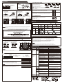
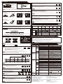
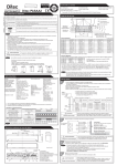
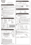
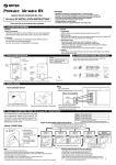
ENGLISH
OA-AXIS I / II
DETECTION AREA
: Emitting spots
: Emitting spots
(Can be elminated)
A
Motion / Presence
detection
MANUFACTURER'S STATEMENT
Read this operation manual carefully before use to ensure proper operation of the sensor.
Failure to read this operation manual may cause improper sensor operation and may result in serious injury or death of
person.The meanings of the symbols are as follows. Please study the following first and then read the contents of this
operation manual.
WARNING
CAUTION
NOTE
Motion detection
Disregard of caution may cause the improper operation causing injury of person or damage to
objects.
NOTE
WARNING
Do not wash, disassemble, rebuild or repair the sensor, otherwise
it may cause electric shock or breakdown of equipments.
Danger of electric shock.
NOTE
: OA-AXIS I /
Form C relay
50V 0.3A Max.(Resistance load)
OA-AXIS II /
1st to 3rd rows / Form C relay
50V 0.3A Max. (Resistance load)
3rd to 5th rows / Form C relay
50V 0.3A Max.(Resistance load)
: Approx. 0.5 sec.
Output hold time
: <0.3 sec.
Response time
Operating temperature : -20 to +55 C(-4 to 131 F)
: IP44
IP rate
: 320g (11.2oz)
Weight
: 1 Cable 3m (9'10")
Accessories
1 Operation manual
2 Mounting screws
1 Mounting template
1 Area adjustment tool
H
D
E
F
G
I
2.20(7'2 5/8")
2.50(8'2 7/16")
2.70(8'10 5/16")
3.00(9'10 1/8")
3.50(11'5 13/16")
B
0.14(5 1/2")
0.16(6 5/16")
0.18(7 1/16")
0.20(7 7/8")
0.23(9 1/16")
C
0.42(1'4 9/16")
0.48(1'6 7/8")
0.52(1'8 1/8")
0.58(1'10 13/16")
0.67(2'2 3/8")
D
0.82(2'8 5/16")
0.93(3' 5/8")
1.00(3'3 3/8")
1.10(3'7 5/16")
1.30(4'3 3/16")
E
1.35(4'5 1/8")
1.54(5' 5/8")
1.66(5'5 3/8")
1.85(6' 13/16")
2.16(7'1 1/16")
F
1.90(6'2 13/16")
2.17(7'1 7/16")
2.34(7'8 1/8")
2.60(8'6 3/8")
3.03(9'11 5/16")
G
1.51(4'11 7/16")
1.63(5'4 3/16")
1.81(5'11 1/4")
2.11(6'11 1/16")
H
1.33(4'4 3/8")
2.05(6'8 11/16")
2.32(7'7 5/16")
2.51(8'2 13/16")
2.79(9'1 13/16")
3.26(10'8 3/8")
I
2.78(9'1 7/16")
3.15(10'4")
3.40(11'1 7/8")
3.79(12'5 3/16")
4.42(14'6")
The actual detection area may become smaller depending on the ambient light, the color / material of the
object or the floor as well as the entry speed of the object.
NOTE
*The values of the chart above is of the emitting spots, but not of the detection area.
INSTALLATION
NOTE
The following conditions are not suitable for the sensor installation.
-Fog or exhaust emission around the door.
-Wet floor
-Vibrating header or mounting surface.
.
-Moving objects or a heating
radiator in the detection area.
-Highly reflecting floor or the presence of highly reflecting objects around the door.
Output
1
1. Affix the mounting template at the desired mounting position.
2. Drill two mounting holes of ø3.4mm (ø1/8”).
3. To pass the cable through to the header, drill a wiring hole of ø8mm (ø5/16”).
4. Remove the mounting template.
5. Remove the housing cover. Attach the sensor to the mounting surface with two mounting screws.
Header
Sensor
Y
The specifications herein are subject to change without prior notice due to improvements.
X
OUTER DIMENSIONS AND PART NAMES
MOUNTING TEMPLATE
267(10 1/2")
7.5(5/16")
125(4 15/16")
43(1 11/16")
36(1 7/16")
C
A
SPECIFICATIONS
: OA-AXIS I / OA-AXIS II
Model
: Silver / Black
Cover color
: 2.0 (6'7") to 3.5m (11'5")
Mounting height
: See DETECTION AREA
Detection area
: Active Infrared Reflection
Detection method
Depth angle adjustment : 1st to 3rd rows / -6 to +6
4th and 5th rows / +26 to +44
: 12 to 24VAC( 10%)
Power supply
12 to 30VDC( 10%)
: OA-AXIS I < 3VA
Power consumption
OA-AXIS II < 4VA
: Green / Stand-by
Operation LED
Blinking Red / 1st row detection
Red / 2nd row detection
Orange / 3rd to 5th rows detection
B
[m(feet,inch)]
Special attention is required to the section of this symbol.
1. This sensor is a non-contact switch intended for header mount / wall mount of an automatic door.
Do not use for any other applications. This sensor cannot be used for industrial doors or shutters,
when used, proper operation and safety cannot be guaranteed.
2. When setting the sensor's detection area, make sure there is no traffic around the installation site.
3. Before turning the power on, check the wiring to prevent damage or malfunction of equipments that are connected
to the sensor.
4. Only use the sensor as specified in the operation manual provided.
5. Be sure to install the sensor in accordance with the local laws and standards of the country in which the sensor is
installed.
6. Before leaving the job site make sure that the sensor is operating properly and instruct the building owner/operator
on proper operation of the door and the sensor.
7.The sensor setting can only be changed by an installer or service engineer. When changed, register the changed
setting and dates in the maintenance logbook accompanying the door.
1st row
2nd row
3rd row
4th row
5th row
Sensor setting
1st to 3rd rows : +6
4th and 5th rows : +44
Disregard of warning may cause the improper operation causing death or serious injury of
person.
H
Door
45(1 3/4")
H: Height from the floor to the bottom of the header
Y: Distance between the bottom of header and the sensor.
Floor
X: Distance between the door and the mounting surface
62.3(2 7/16")
5915031 JAN 2009
: Detection area
0
50 (1 15/16")
100 (3 15/16")
150 (5 7/8")
200 (7 7/8")
250 (9 13/16")
300 (11 13/16")
[mm (inch)]
PRESENCE
Depth
Width
A
5 rows
ON
nity
Immu
10
ON
Middle
60sec.
B
4 rows
OFF
OFF
High
180sec.
C
3 rows
S-High
∞
D
2 rows
ence
itivity
PresTimer
3,4
1,2
15sec.
Low
Sens
y
uenc
5,6
Freq
t
Rowjustmen
Ad
7,8
Snow
Mode9
R
Narrow
Wide
26°
(4)
(1) Connector
(2) Mounting holes
(3) Operation LED
(4) Depth angle adjustment screw
44°
Risk of getting caught.
lation
Instal Mode
16
ON
OFF
L
R
1
2
3
4
5
6
7
8
Not applicable
NOTE
9 10 11 12 13 14 15 16
Narrow
0°
35° Deep
Shallow
-3°
30.5°
3°
39.5°
-6°26°
(3)
CAUTION
ACTIVATION
Depth
Width
6°
-6°
L
Wide
2,000 (6' 6")
2,200 (7' 2")
200 (7 7/8")
200 (7 7/8")
130 (5 1/8”)
-
200 (7 7/8")
200 (7 7/8")
150 (5 7/8”)
110 (4 5/16”)
-
-
2,500 (8' 2")
No limit
200 (7 7/8")
200 (7 7/8")
170 (6 11/16")
130 (5 1/8”)
-
3,000 (9' 10")
200 (7 7/8")
200 (7 7/8")
200 (7 7/8")
150 (5 7/8”)
120 (4 3/4”)
-
Make sure to affix the mounting template as described in the above chart.
Otherwise, it can be dangerous since there may be no presence detection area
around the threshold. Install the sensor as low as possible on the header.
The sensor mounting position may be limited depending on the header thickness and the mounting height.
5730350
6°
44°
(5)
H
X
(2)
(1)
[mm(feet,inch)]
Maximum mounting distance (Y)
(6)
(7)
(8)
2
(5) Width adjustment screws
(6) Dipswitches
(7) Detection window
(8) Area adjustment tool
Wire the cable to the door controller properly as shown in the drawing below.
Grey
Grey
OA-AXIS I
White
Yellow
Green
Grey
Grey
OA-AXIS II
White
Yellow
Green
Power supply
to 24VAC 10%
} 12
12 to 30VDC 10%
Common (COM.)
Normally open (N.O.)
Normally closed (N.C.)
Power supply
to 24VAC 10%
} 12
12 to 30VDC 10%
Common (COM.)
Normally open (N.O.)
Normally closed (N.C.)
White Str. Common (COM.)
Yellow Str. Normally open (N.O.)
Green Str. Normally closed (N.C.)
3rd to 5th *
rows output
1st to 3rd *
rows output
*The outputs from the 3rd row overlaps.
WARNING
Danger of electric shock.
3
1.Plug the connector of the sensor.
2.Supply power to the sensor. Adjust the detection area and set the dipswitches. (See ADJUSTMENTS)
NOTE
4
Before starting the procedure, ensure that the power is turned OFF.
When passing through the cable to the hole, make sure not to tear the shield,
otherwise it may cause electric shock or breakdown of the sensor.
Make sure to connect the cable correctly to the door controller before turning the power ON.
To enable the presence detection, do not enter the detection area for 10 seconds after supplying the power.
Place the housing cover .
If wiring is to be exposed, break the knockout.
WARNING
Danger of electric shock.
Do not use the sensor without the cover.
When using the cable knockout, install the sensor indoors or use the rain-cover
(Separetely available) otherwise electric shock or breakdown of
the sensor may occur.
ADJUSTMENTS
1
Area depth angle adjustment
3-4 Setting the area depth
Area adjustment tool
4th and 5th rows and
area width adjustment
1st to 3rd rows
adjustment
Depth angle
adjustment screw
A
Simultaneous C
adjustment
The detection area depth can be changed by
the area adjustment tool.
When adjusting the 1st to 3rd rows close to the door, follow 3-7 Installation mode.
*When 2 rows setting is selected, only the
presence detection area remains.
B
NOTE
3-5
1-1. Independent adjustment
1st to 3rd rows
Depth angle adjustment screw
for 1st to 3rd rows
The 5th, 4th, and 3rd rows can be eliminated by
combining dipswitches 7 and 8.
5 rows
4 rows
3 rows
2 rows
7 8
7 8
7 8
7 8
Always check the area according to the expected entry speed and determine the appropriate number
of rows.
When setting motion and motion / presence detection area sparately, make sure that there is no gap between
two areas.
OFF
ON
Setting the snow mode
Set this switch to ON, if the sensor is used in a region with snow.
Shallow
4th and 5th rows
Deep
Shallow
Depth angle adjustment screw
for 4th and 5th rows
Deep
3-6 Setting the immunity
9
9
OFF
ON
10
10
OFF
ON
16
16
Set this switch to ON, when less influence by the header vibration is required.
Red
Blue
Use the area adjustment tool (A) as shown above and
change the depth of the detection area by turning the depth
angle adjustment screw.
[m]
Use the area adjustment tool (B) as shown above and
change the depth of the detection area by turning the depth
angle adjustment screw.
[m]
[m]
Deep Shallow
[m]
3-7 Installation mode
Use this switch to ON when adjusting the presence detection area
close to the door face.
* During the installation mode, only the 1st row remain.
* Door open state
* Operation LED glows yellow.
Deep Shallow
CHECKING
Check the operation according to the chart below.
Check the area position with Red LED of the Operation LED using a tool such as a reflecting mirror.
Make sure the detection area does not overlap with the door / header,otherwise ghosting / signal saturation
may occur.
Do not place any highly reflecting objects in the detection area, otherwise signal saturation may occur.
NOTE
NOTA
Entry
Power off
Outside of
detection
area
Entry into
4th or 5th row
Entry into
3rd row
Status
-
Stand-by
Motion
detection active
Motion/Presence
detection active
Operation LED
None
Green
OA-AXIS I
REFERENCE Area depth adjustment with INFRARED FINDER (Separately available)
White : COM.
Yellow : N.O.
Green : N.C.
White Str. : COM.
Yellow Str. : N.O.
Green Str. : N.C.
Entry into
2nd row
Orange
Entry into
1st row
Presence
detection
Red
Blinking Red
Output
Output from
1st to 3rd
rows *
OA-AXIS II
Output from
3rd to 5th
rows *
1. Turn the depth adjustment screw to the right (Deep) to place the area most away from the door.
2. Set INFRARED FINDER sensitivity to "H" (High) and place it on the floor as shown below.
Detection area
*The outputs from the 3rd row overlaps.
INFRARED FINDER
Detection area
3. Turn the depth adjustment screw to the left (Shallow) until the emitting area is placed at the position where
INFRARED FINDER is in the low detection status (Slow Red blinking).
INFORM BUILDING OWNER / OPERATOR OF THE FOLLOWING ITEMES
WARNING
1-2. Simultaneous adjustment
For the simultaneous adjustment of 1st to 5th rows, use the adjustment tool (C).
2
Width detection area adjustment
1st to 3rd rows
1-3
10 - 12
Eliminated
Eliminated
[m]
Front view
4th and 5th rows
1-3
NOTE
NOTA
10 - 12
Eliminated
1. When turning the power on, always walk-test the detection area to ensure proper operation.
2. Do not place any objects that move or emit light in the detection area. (e.g. Plant, illumination, etc.)
Eliminated
Narrow
Narrow
Wide
Wide
Width adjustment
screw (Left)
1
2
Width adjustment
screw (Right)
TROUBLESHOOTING
12
11
10
3
456 7 8 9
NOTE
The actual detection area may become smaller depending on the ambient light, the color / material of the object and
the floor as well as the entry speed of the object.
3
Dipswitch settings
Not applicable
1 2 3 4 5 6 7 8
9 10111213141516
1,2
3,4
5,6
7,8
9 10 11 to 15
16 :Sensitivity
:Presence detection timer
:Frequency
:Row adjustment
3-1 Setting the sensitivity
Normally set to "Middle". " Low" decreases the sensitivity and "High / S-High"
increases the sensitivity.
Low
1
3-2 Setting the presence detection timer
The 1st and 2nd rows have the presence detection function.
The presence detection timer can be selected from 4 settings.
NOTE
1. Always keep the detection window clean. If dirty, wipe the window lightly with a damp cloth.
(Do not use any cleaner or solvent.)
2. Do not wash the sensor with water.
3. Do not disassemble, rebuild or repair the sensor yourself, otherwise electric shock may occur.
4. When an operation LED blinks green, contact your installer or service engineer.
5. Always contact your installer or service engineer when changing the settings.
6. Do not paint the detection window.
2
15 sec.
3
4
High
1
1
2
2
Operation
LED
Door does not
open when a
person enters
the detection
area.
None
Door opens
when no one
is in the
detection area.
(Ghosting)
: Snow mode
: Immunity
: Not applicable
: Installation mode
Middle
Problem
Unstable
Unstable
S- High
1
4
3
4
3
3-3 Setting the frequency
6
5
6
5
6
5
Vibration of the header.
Set the sensitivity lower or the immunity to ON.
Water drops on the detection window.
Use the rain-cover (Separately available).
Or install in a place keeping the waterdrops off.
The detection area overlaps
with that of another sensor.
Check ADJUSTMENTS 3-3.
The detection area overlaps
with the door / header.
Adjust the detection area to "Deep" (Outside).
Wipe the detection window with a damp cloth.
(Do not use any cleaner or solvent.)
Set the sensitivity lower.
Set the snow mode to ON.
Remove the objects.
Wet floor.
The exhaust emission or fog penetrate into the detection area.
Check the installation condition referring to
INSTALLATION on the reverse side.
Red
or
Orange
Proper
Sudden change in the detection area.
Check ADJUSTMENTS 3-1 & 3-2.
If the problem still persists, hard-reset the
sensor.(Turn the power OFF and ON again.)
Check the wires and connector.
Twice
Green
blinking
The relay is reaching the end of its
life cycle.
Contact your installer or the sales engineer.
Slow
Green
blinking
Signal saturation
Remove highly reflecting objects from the
detection area. Or lower the sensitivity.
Or change the area angle.
The detection area overlaps with
the door / header.
Adjust the detection area to "Deep" (Outside).
Wrong wiring or connection failure.
Check the wires and connector.
4
6
Set to the stated voltage.
Check the wires and connector.
Check ADJUSTMENTS 1 & 2.
Set the sensitivity higher.
Set the presence detection timer longer.
It snows and pours.
Objects that move or emit light in the
detection area.
(Ex.Plant, illumination,etc.)
Setting 1 Setting 2 Setting 3 Setting 4
5
Power supply voltage.
Wrong wiring or connection failure.
Wrong detection area positioning.
Sensitivity is too low.
Short presence detection timer.
Dirty detection window.
Sensitivity is too high.
To enable the presence detection, do not enter the detection area for 10 seconds after setting the timer.
When using more than two sensors close to each other, set the different
frequency for each sensor by combining dipswitch 5 and 6.
Possible countermeasures
Reflecting objects in the detection area. Remove the objects.
Or reflecting light on the floor.
2
60 sec. 180 sec.
3
Possible cause
Door remains
open
Door remains
closed
Proper
Wrong wiring or connection failure.
ENGLISH
COMPLIANCE
ORIGINAL
DETECTION AREA
Read this operation manual carefully before use to ensure proper operation of this product.
Failure to read this operation manual may cause improper operation and may result in serious injury or
death of a person.The meanings of the symbols are as follows.
NOTE
: Emitting spots
Disregard of warning may cause the improper operation causing death or serious injury of
a person.
Disregard of caution may cause the improper operation causing injury of a person or damage to
objects.
Special attention is required to the section of this symbol.
It is required to check the operation manual if this symbol is shown on the product.
: Emitting spots
(Can be eliminated)
A
: Detection Area
Motion / Presence
detection
Motion detection
B
1st row
2nd row
3rd row
4th row
1. This product is a non-contact switch intended for header mount or wall mount for use on an automatic sliding door.
Do not use for any other applications.
2. When setting the sensor's detection area, make sure that there is no traffic around the installation site.
3. Before turning the power ON, check the wiring to prevent damage or malfunction of equipment connected to
the product.
4. Only use the product as specified in the operation manual provided.
5. Be sure to install and adjust the sensor in accordance with the local laws and standards of the country in which
the product is installed.
6. Before leaving the installation site make sure that the product is operating properly and instruct the building
owner/operator on proper operation of the door and the product.
7.The product settings can only be changed by an installer or service engineer. When changed, the
changed settings and the date shall be registered in the maintenance logbook accompanying the door.
WARNING
Do not wash, disassemble, rebuild or repair the sensor, otherwise
it may cause electric shock or breakdown of the equipment.
Danger of electric shock.
NOTE
C
D
E
F
5th row
NOTE
H
Charts show the values in the following
depth angle adjustment settings ;
G
1st to 3rd rows : +6°
4th and 5th rows : +44°
I
Emitting area
[m(feet,inch)]
A
B
C
D
E
F
2.00 (6'6")
0.13 (5")
0.38 (1' 3")
0.74 (2' 5")
1.23 (4' 1")
1.74 (5' 9")
2.20 (7'2")
0.14 (6")
0.42 (1' 5")
0.82 (2' 8")
1.35 (4' 5")
1.90 (6' 3")
2.50 (8'2")
0.16 (6")
0.48 (1' 7")
0.93 (3' 1")
1.54 (5' 1")
2.17 (7' 1")
2.70 (8'10")
0.18 (7")
0.52 (1' 8")
1.00 (3' 3")
1.66 (5' 5")
2.34 (7' 8")
3.00 (9'10")
0.20 (8")
0.58 (1' 11")
1.10 (3' 7")
1.85 (6' 1")
2.60 (8' 6")
G
H
I (*)
X
1.06 (3' 6")
1.86 (6' 1")
2.52 (8' 3")
0.19 (8")
1.33 (4' 4")
2.05 (6' 9")
2.78 (9' 2")
0.21 (8")
1.51 (4' 11")
2.32 (7' 7")
3.15 (10' 4")
0.24 (9")
1.63 (5' 4")
2.51 (8' 3")
3.40 (11' 2")
0.26 (10")
1.81 (5' 11")
2.79 (9' 2")
3.79 (12' 5")
0.28 (11")
X is the distance between the 1st row and the mounting surface.
Detection area
To comply with DIN 18650, make sure that the detection area is within the values in the chart below.
The following conditions are not suitable for sensor installation.
-Fog or exhaust emission around the door.
-Wet floor.
-Vibrating header or mounting surface.
-Moving objects or objects that emit light near the detection area.
-Highly reflecting floor or highly reflecting objects around the door.
A
C
G
I
2.00 (6'6")
0.23 (9")
1.02 (3' 4")
2.41 (7' 11")
2.20 (7'2")
0.24 (10")
1.10 (3' 7")
2.54 (8' 4")
Test conditions required by DIN 18650
Floor : Kodak Grey card
Detection object :
DIN 18650 Test body (Mat black)
The values above are when the sensitivity is set to "Middle" and speed of detection object is 50mm / sec..
The values above are those of the detection area when tested referring to the test conditions of DIN 18650.
(The emitting area is as shown in Emitting area above.)
*: When installed at higher than 2.35m(7'8"), DIN 18650 requirements are fulfilled only within the area width "I"
of 3m(9'10").
NOTE
The actual detection area may become smaller depending on the ambient light, the color / material of
the object or the floor as well as the entry speed of the object.
The sensor may not be activated when the entering speed of the object or a person is slower than
50mm / sec. or faster than 1500mm / sec.
SPECIFICATIONS
Model
Cover color
Mounting height
Detection area
Detection method
Depth angle
adjustment
Power supply (*2 )
: OA-AXIS T
: Silver / Black
: 2.0 (6'6") to 3.0m (9'10")
: See DETECTION AREA
: Active infrared reflection (*1 )
: 1st to 3rd rows / -6 to +6°
4th and 5th rows / +26 to +44°
: 12 to 24VAC ±10% (50 / 60 Hz)
12 to 30VDC ±10%
Power consumption : < 2.5W (< 4VA at AC)
Operation indicator : See chart below
Test input
: Opto coupler
Voltage / 5 to 30VDC
Current / 6mA Max. (30VDC)
Activation output : When 3rd, 4th or 5th row detects.
Form A relay
50V 0.3A Max. (Resistance load)
Safety / Test output
: When 1st or 2nd row detects.
Opto coupler (NPN)
Voltage / 5 to 50VDC
Current / 100mA Max.
Dark current / 600nA Max.
(Resistance load)
Noise level
: <70dBA
Output hold time
: <0.5 sec.
Response time
: <0.3 sec.
Operating temperature : -20 to +55°C (-4 to 131°F)
Operating humidity
: <80%
IP rate
: IP54
Category
: 2 (EN ISO 13849-1 : 2008)
Performance level
: d (EN ISO 13849-1 : 2008)
Weight
: 320g (11.2oz )
Accessories
: 1 Operation manual
2 Mounting screws
1 Mounting template
1 Area adjustment tool
1 Cable 3m (9'10")
(8 × 0.22mm² AWG24 ) (*3 )
INSTALLATION
1
Operation indicator
Status
Operation indicator color
Stand-by (Setting mode)
Blinking Blue
H : Height from the floor to the bottom of the header
Y : Distance between the bottom of the header and the sensor
X : Distance between the door and the mounting surface
(The mounting height is "H + Y".)
Sensor
Y
X
H
Door
1sec.
Floor
CAUTION
Stand-by (Operation mode)
Green
1st row detection
Blinking Red
2nd row detection
Maximum mounting distance (Y)
X
Yellow
Stand-by (Installation mode)
Risk of getting caught.
Red
Wrong dipswitch setting
2
Red & Green blinking
Signal saturation
Slow Green blinking
Sensor failure
Fast Green blinking
The specifications herein are subject to change without prior notice due to improvements.
267(10 1/2")
125(4 15/16")
36(1 7/16")
To the connector
of the sensor
43(1 11/16")
45(1 3/4")
WARNING
Danger of electric shock.
3
[mm (inch)]
st
t
y / Te
ncy Row
tmen
Safeter
eque
5,6 adjus 7,8
tim 3,4 Fr
15sec.
5 rows
Setting 1
60sec.
High
180sec.
S-High
Setting 2
4 rows
Setting 3
3 rows
Setting 4
2 rows
st
/ Te
t
g
inpu
unity Self itorin Safetyut
Imm 9 mon 10 outp 11 Test 12
ON
Low
Disable Low
OFF
Enable
High
High
L
n
ut
tio
inp
iva t
st
Teelay Actutpu
d
13 o
14
20msec.
10msec.
1st to 3rd rows
Width
N.C.
N.O.
4th and 5th rows
Depth
R
-6°
6°
26°
L
Operation
mode
R
Attention
Setting For dipswitch setting,
mode change it to "Setting
mode".
When setting finished,
set it to "Operation
mode".
tion
alla
Instode
m
16
ON
0°
35° Deep
Shallow
-3°
30°
3°
40°
Not
applicable
OFF
1 2 3 4 5 6 7 8
Narrow
Wide
(4)
44°
Function key
Width
Depth
-6° 26°
(3)
(9)
(2)
(1)
Low
0.20 (7")
0.20 (7")
0.13 (5”)
-
2.30 (7' 6")
0.20 (7")
0.20 (7")
0.15 (5”)
0.12 (4”)
-
2.50 (8' 2")
No limit
0.20 (7")
0.20 (7")
0.19 (7")
0.14 (5”)
0.11 (4")
-
2.80 (9' 2") 3.00 (9'10")
0.20 (7")
0.20 (7")
0.20 (7")
0.15 (5”)
0.12 (4”)
-
0
0
0
0
0
-
Make sure to affix the mounting template as described in the above chart ,
otherwise it can be dangerous since there may be no detection area around
the threshold. Install the sensor as low as possible on the header.
9 10 11 12 13 14 15 16
Narrow
5730870
Wide
6°44°
(5)
(6)
(7)
(8)
(1) Connector
(2) Mounting holes
(3) Operation indicator
(4) Depth angle adjustment screw
(5) Width adjustment screws
(6) Function key
(7) Dipswitches
(8) Detection window
(9) Area adjustment tool
4
1.White
2.Brown
3.Green
4.Yellow
supply
} Power
12 to 24VAC±10% /12 to 30VDC±10%
Activation output
Form A relay 50V 0.3A Max.
5.Pink (+)
6.Blue (-)
Safety / Test output
Opto coupler(NPN) / Voltage: 5 to 50VDC
7.Red (+)
8.Black (-)
Test input
Opto coupler / Voltage: 5 to 30VDC
Before starting the procedure, make sure that the power is turned OFF.
When passing the cable through the hole, do not tear the shield.
otherwise it may cause electric shock or breakdown of the sensor.
1.Plug the connector of the sensor.
2.Supply power to the sensor. Adjust the detection area and set the dipswitches. (See ADJUSTMENTS)
NOTE
Middle
2.00 (6' 6")
Wire the cable to the door controller as shown below.
OUTER DIMENSIONS AND PART NAMES
itivity
Sens 1,2
H
0
0.05 (2")
0.10 (4")
0.15 (6")
0.20 (8")
0.25 (10")
0.30 (12")
[m (feet,inch)]
Orange
3rd, 4th or 5th row detection
NOTE
1sec.
1. Affix the mounting template at the desired mounting position.
(When setting the detection area close to the door, mount the sensor according to the chart below.)
2. Drill two mounting holes of ø3.4mm (ø1/8”).
3. To pass the cable through the header, drill a wiring hole of ø8mm (ø5/16”).
4. Remove the mounting template.
5. Remove the housing cover. Fix the sensor to the mounting surface with the two mounting screws.
Header
*1 : The 1st and 2nd rows have presence detection function.
*2 : When using this sensor, the sensor has to be connected to a door system which has the SELV circuit.
*3 : Overcurrent protection with less than 2A.
63(2 1/2")
TM-0045-8
Notified Body: TÜV SÜD Product Service GmbH, Daimlerstraße 40 60314 Frankfurt Germany
MANUFACTURER'S STATEMENT
STATEMENT
MANUFACTURER'S
CAUTION
Machinery Directive 2006/42/EC
prEN 16005
EN 12978+A1:2009
EN ISO 13849-2:2008
EN 61696-3:2001 clause 4. 3. 5 and 5. 4. 7. 3
7(1/4")
5914953 JUL 2011
OA-AXIS T
WARNING
DIN 18650-2:2010
EN ISO 13849-1:2008
DIN 18650-1:2010
EMC Directive 2004/108/EC
Make sure to connect the cable correctly to the door controller before turning the power ON.
When turning the power ON or after adjusting the settings, do not enter the detection area for more
than 10 seconds in order to enable the presence detection.
Do not touch the dipswitches before turning the power ON, otherwise an error occurs.
When changing the settings of dipswitch, see ADJUSTMENTS 3 Dipswitch settings.
Place the housing cover.
If wiring is to be exposed, break the knockout.
WARNING
Danger of electric shock.
Do not use the sensor without the cover.
When using the cable knockout, install the sensor indoors or use the rain-cover
(Separately available) otherwise electric shock or breakdown of
the sensor may occur.
ADJUSTMENTS
1
Area depth angle adjustment
3-7.Setting the Safety / Test output (to door controller)
Area adjustment tool
Depth angle
adjustment screw
A
3-8.Setting the test input (from door controller)
Dipswitch12 is the test input (from door controller).
Make sure that the detection area does not overlap with the door / header, and there is no highly reflecting
object near the detection area otherwise ghosting / signal saturation may occur.
NOTE
[m]
Shallow
Depth angle adjustment screw
for the 1st to 3rd rows
[m]
Deep
NOTE
2.0
Red
3.0
3.0
Use the area adjustment tool (A) as shown above to
change the area depth angle for the 1st to 3rd rows.
Shallow
2.0
1.0
1.0
0
Deep
[m]
2.0
Blue
3.0
3.0
Use the area adjustment tool (B) as shown above to
change the area depth angle for the 4th and 5th rows.
3.0
2.0
0
1.0
2.0
1.0
1.0
0
INFRARED FINDER
Detection area
3. Turn the depth angle adjustment screw to the left (Shallow) until the emitting area is placed at the position where
INFRARED FINDER is in the low detection status (Slow Red blinking).
Area width adjustment
[m]
1
2
3
10 11 12
2.0
Wide
Width adjustment
screws (Left)
Width adjustment
screws (Right)
3.0
1
2
2.0
3
5
4
1.0
6
7
9 10 11 12
8
0
1.0
Dipswitch settings
Function key
Follow these steps to change the settings of dipswitches.
1.Change the function key from the "Operation mode" to the "Setting mode".
During the "Setting mode", the operation indicator is blinking Blue
Setting mode
(only when stand-by status) and the door remains open.
2.Change the dipswitch settings.
3.When the setting is finished, change the function key back to the "Operation mode".
NOTE
Operation mode
When the above procedures (1-3) are not followed, an error (Red & Green blinking) occurs.
Make sure to use the sensor only in the" Operation mode".
The sensor does not operate properly in the "Setting mode".
3-1.Setting the sensitivity
Refer to the chart below for the suitable sensitivity to your installation environment.
Low
Middle
High
S-High
12
12
12
12
Floor condition
NOTE
2.2 (7' 2")
2.5 (8' 2")
Entry
Power OFF
Outside of
detection
area
Entry into
3rd to 5th row
Status
-
Stand-by
Motion
detection active
Operation indicator
None
Green
Orange
Middle
High
S-High
Middle reflection
Low
Middle
Middle
S-High
-Concrete
High reflection
Low
Low
Middle
High
Safety
/ Test
output
16
3-4.Setting the row adjustment
30sec.
60sec.
180sec.
34
34
34
Blinking Red
Red
Green
High
OFF
ON
OFF
ON
11
Low
OFF
OFF
ON
OFF
1. When turning the power ON, always walk-test the detection area to ensure the proper operation.
2. Do not place any objects that move or emit light in the detection area. (e.g. Plant, illumination, etc.)
Door operation Operation
indicator
Door does not
open when a
person enters
the detection
area.
Door opens
when no one
is in the
detection area.
(Ghosting)
34
56
56
56
None
2rows
78
78
78
78
3-5.Setting the immunity
Set dipswitch 9 to ON when the sensor operates by itself (Ghosting).
When dipswitch 9 is set to ON ,the actual detection area may become smaller.
OFF
Possible countermeasures
Possible cause
Wrong power supply voltage
Wrong wiring or connection failure
Wrong detection area positioning
Sensitivity is too low.
Short presence detection timer
Dirty detection window
Set to the stated voltage.
Check the wires and connector.
Check ADJUSTMENTS 1 , 2 & 3.(*)
Proper
Wrong wiring or connection failure
Check the wires and connector.
Unstable
Objects that move or
emit light in the detection area.
Remove the objects.
The detection area overlaps
with that of another sensor.
Check ADJUSTMENTS 3-3.(*)
Waterdrops on the detection window
Use the rain-cover (Separately available).
Or install in a place keeping the waterdrops off.
Detection area overlaps with door /
header.
Adjust the detection area to "Deep" (Outside).
Sensitivity is too high.
Others
Sudden change in the detection area
Set the sensitivity lower.(*)
Set the immunity to ON.(*)
Check ADJUSTMENTS 3-1 & 3-2.(*)
If the problem still persists, hard-reset the
sensor.(Turn the power OFF and ON again.)
Wrong wiring or connection failure
Wrong setting of dipswitches.
Installation mode is set to ON.
Check the wires and connector.
Check ADJUSTMENTS “3-6”- “3-10”.(*)
Set installation mode to OFF.(*)
Unstable
Proper
Slow
Green
blinking
Proper
operation
ON
9
9
Enable
Disable
10
10
Set the sensitivity higher.(*)
Set the presence detection timer longer.(*)
Wipe the detection window with a damp cloth.
(Do not use any cleaner or solvent.)
Set to the"Operation mode".
Set the sensitivity higher.(*)
Wipe the detection window with a damp cloth.
(Do not use any cleaner or solvent.)
Contact your installer or service engineer.
Sensor failure
Signal saturation (1st or 2nd row)
Remove highly reflecting objects from the
detection area. Or lower the sensitivity.(*)
Or change the area depth angle for 1st to 3rd rows.
Adjust the detection area to "Deep" (Outside).
The detection area overlaps with
the door / header.
56
3rows
To comply with DIN18650 dipswitch 10 must be set to "Enable".
Stand-by
11
Yellow
Blinking Blue Wrong setting of function key
Fast
Sensitivity is too low.
Green
Dirty detection window
blinking
4rows
When the door remains open and the LED indicator shows fast or slow green
blinking, please refer to the TROUBLESHOOTING.
If the door still remains open, set dipswitch 10 to "Disable".
Motion / Presence
detection active
Outside of
detection
area
N.C.
-Tile
-Marble
5rows
3-6.Setting the self monitoring
Entry into
1st row
14
Door remains
open
Set the depth rows with dipswitches 7 and 8.
When "2rows" are selected, the activation output
is disabled.
Entry into
2nd row
TROUBLESHOOTING
Setting1 Setting2 Setting3 Setting4
When using more than two sensors close to each other, set the different
frequency for each sensor by dipswitches 5 and 6.
NOTE
16
N.O.
NOTE
To enable the presence detection, do not enter the detection area for 10 seconds after setting the timer.
3-3.Setting the frequency
NOTE
ON
INFORM BUILDING OWNER / OPERATOR OF THE FOLLOWING ITEMS
Special attention to the setting is required when the door is used often by the elderly or children.
Please adjust the sensitivity and the presence detection timer according to your risk assessment.
The 1st and 2nd rows have the presence detection function.
To comply with DIN 18650, set the timer to " 60sec." or more.
NOTE
OFF
14
For example
Middle
3-2.Setting the presence detection timer
NOTE
3.0 (9' 10")
-Carpet
-Dark color floor
Low reflection
14
CHECKING
Mounting height [ m (feet,inch) ]
2.0 (6' 6")
14
If the function key is set back to the "Operation mode" while the installation mode is still ON, an error occurs.
2.0
When adjusting the width adjustment screws, make sure to turn until it clicks otherwise the proper operation may not
be obtained.
1 2 3 cannot be eliminated separately, neither can 10 11 12 .
3
N.C.
WARNING
Narrow
Wide
13
1. Always keep the detection window clean. If dirty, wipe the window with a damp cloth.(Do not use any cleaner / solvent.)
2. Do not wash the sensor with water.
3. Do not disassemble, rebuild or repair the sensor yourself, otherwise electric shock may occur.
4. When the operation indicator blinks Green, contact your installer or service engineer.
5. Always contact your installer or service engineer when changing the settings.
6. Do not paint the detection window.
Eliminated Eliminated
Narrow
NOTE
Front view
0
4th and 5th rows
10 11 12
13
N.O.
Set dipswitch 16 to ON when adjusting the 1st row close to the door.
When the setting is finished, set to OFF.
During the installation mode, only the 1st row remains, and the operation indicator glows Yellow.
Activation
output
Detection area
Eliminated
Uni
Check the operation in the operation mode according to the chart below.
1. Turn the depth angle adjustment screw to the right (Deep) to place the detection area most away from the door.
2. Set INFRARED FINDER sensitivity to "H" (High) and place it on the floor as shown below.
3
Bi
2.0
REFERENCE Area depth adjustment with INFRARED FINDER (Separately available)
2
12
Uni-directional function is disabled in case presence area detection continues more than 5sec.
For the simultaneous adjustment of the 1st to 5th rows, use the adjustment tool (C).
1
12
The delay time between test input and Safety / Test output is 10msec.
Set dipswitch 14 to "N.O." (Normally Open) or "N.C." (Normally Closed) .
NOTE
1-2.Simultaneous adjustment
Eliminated
Low
3-11.Installation mode
[m]
Deep Shallow
1st to 3rd rows
High
3-10.Setting the activation output
3.0
2.0
0
1.0
2.0
Depth angle adjustment screw
for the 4th and 5th rows
2
11
When Dipswitch13 is "Uni", uni-directional function is activated.
This function enables the door to close earlier if a person walks away from the door.
NOTE
Deep Shallow
4th and 5th rows
11
3-9.Settings the direction recognition
1-1.Independent adjustment
1st to 3rd rows
Low
B
C
When adjusting the 1st row close to the door,
follow 3-11 Installation modefor the easier adjustment.
High
Dipswitch11 is the Safety / Test output (to door controller).
Red &
Green
blinking
Wrong setting of dipswitch
1. Set the function key to the "Setting mode".
2. Change the dipswitch 16 setting (ON OFF or
OFF ON OFF).
3. Set the function key back to "Operation mode".
Slow
Green
blinking
Signal saturation (3rd, 4th or 5th row)
Remove highly reflecting objects from the
detection area. Or lower the sensitivity.(*)
Or change the area depth angle.
* Before changing these settings, set the function key to the "Setting mode". When finished, set back to the "Operation mode".
Manufacturer
European Subsidiary
OPTEX Co.,LTD.
OPTEX Technologies B.V.
5-8-12 Ogoto Otsu 520-0101, Japan
TEL.: +81(0)77 579 8700
FAX.: +81(0)77 579 7030
WEBSITE: www.optex.co.jp/as/eng/index.html
Tiber 2, 2491 DH The Hague, The Netherlands
TEL.: +31(0)70 419 41 00 FAX.: +31(0)70 317 73 21
E-MAIL: [email protected]
WEBSITE: www.optex.nl
North and South American Subsidiary
OPTEX Technologies Inc.
Corporate Headquarters
3882 Del Amo Blvd., Suite 604 Torrance, CA 90503 U.S.A.
TOLL-FREE: 800 877 6656 FAX.: +1 310 214 8655
WEBSITE: www.optextechnologies.com
East Coast Office
8510 McAlpines Park Drive, Suite 108 Charlotte,
NC 28211 U.S.A.
TOLL-FREE: 800 877 6656 FAX.: +1 704 365 0818
WEBSITE: www.optextechnologies.com