1
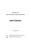
INSTALLATION
MANUAL
OIL-FIRED WARM AIR
FURNACE
P2HMX12F08001 P3HMX14F10001
P3HMX20F12001
(Upflow or Horizontal Models)
CONTENTS
P3LBX12F08001 P3LBX14F12001
(Lowboy Models)
INTRODUCTION ...............................................................2
HEAT LOSS ......................................................................2
LOCATION OF UNIT ........................................................2
AIR CONDITIONING .........................................................4
COMBUSTION AIR...........................................................4
CHIMNEY VENTING .........................................................4
OIL TANK..........................................................................6
PIPING INSTALLATION ...................................................6
ELECTRICAL CONNECTIONS ........................................6
CIRCULATING AIR BLOWER..........................................7
OIL BURNER ....................................................................8
FURNACE INSTALLATION SET-UP................................9
MAINTENANCE AND SERVICE.....................................10
OPERATING INSTRUCTIONS .......................................10
TABLE A-1: BECKETT OIL BURNER SET-UP .............11
TABLE A-2: DIRECT DRIVE BLOWER SET-UP ...........11
TABLE A-3: DIRECT DRIVE BLOWER
CHARACTERISTICS ......................................................12
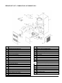
GENERAL DIMENSIONS – P*HMX MODELS ...............14
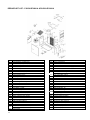
GENERAL DIMENSIONS – P3LBX MODELS................15
APPENDIX B: WIRING DIAGRAM .................................16
WIRING NOTES..............................................................17
R7184 DETAILED SEQUENCE OF OPERATION..........18
TABLE C-1: ST9103 DETAILED SEQUENCE OF
OPERATION ...................................................................20
TABLE C-2: CAD CELL RESISTANCE ........................21
TABLE C-3: R7184 TROUBLESHOOTING...................21
TABLE C-4: SYSTEM AND GENERAL
TROUBLESHOOTING ....................................................24
AIR FILTER LOCATIONS...............................................27
REPAIR PART LIST – P3HMX14F10001 &
P3HMX20F12001 ............................................................28
REPAIR PART LIST – P3LBX12F08001A &
P3LBX14F12001A ..........................................................29
REPAIR PART LIST – P2HMX12F08001 .......................30
REPLACEMENT PART CONTACT INFORMATION ......31
1
Read this manual completely before beginning
installation.
Important: These instructions must be kept with
the furnace for future reference.
HEAT LOSS
IMPROPER INSTALLATION MAY CREATE A CONDITION WHERE THE OPERATION OF THE PRODUCT COULD
CAUSE PERSONAL INJURY OR
PROPERTY DAMAGE.
IMPROPER INSTALLATION, ADJUSTMENT, ALTERATION, SERVICE OR
MAINTENANCE CAN CAUSE INJURY
OR PROPERTY DAMAGE. REFER TO
THIS MANUAL FOR ASSISTANCE OR
ADDITIONAL INFORMATION, CONSULT A QUALIFIED INSTALLER, SERVICE AGENCY OR THE FUEL SUPPLIER.
THIS PRODUCT MUST BE INSTALLED
IN STRICT COMPLIANCE WITH THESE
INSTALLATION INSTRUCTIONS AND
ANY APPLICABLE LOCAL, STATE,
AND NATIONAL CODES INCLUDING
BUT NOT LIMITED TO: BUILDING,
ELECTRICAL
AND
MECHANICAL
CODES.
The furnace area must not be used as a
broom closet or for any other storage
purposes, as a fire hazard may be created. Never store items such as the following on, near or in contact with the
furnace:
1. Spray or aerosol cans, rags,
brooms, dust mops, vacuum cleaners or other cleaning tools.
2. Soap powders, bleaches, waxes or
other cleaning compounds; plastic
items or containers, gasoline, kerosene, cigarette lighter fluid, dry
cleaning fluids, or other volatile fluids.
3. Paint thinners or other painting materials and compounds.
4. Paper bags, boxes, or other paper
or cardboard products.
Never operate the furnace with the
blower door removed. To do so could
result in serious personal injury and/or
equipment damage.
DO NOT USE GASOLINE, CRANKCASE OIL, OR ANY OTHER OIL CONTAINING GASOLINE AS A FUEL FOR
THIS FURNACE.
INTRODUCTION
Please read these instructions completely and carefully before installing and
operating the furnace.
The furnace must be installed and set up
by a qualified contractor.
Model P2HMX12F08001 is an oil fired
forced air multi-positional furnace, with
an output capacity range of 58,000
BTU/Hr. to 79,000 BTU/Hr. Models
P3HMX14F10001 and P3HMX20F12001
are oil fired forced air multi-positional
furnaces, with output capacity ranges of
87,000 BTU/Hr. to 118,000 BTU/Hr.
These models may be installed in the upflow position, as well as both horizontal
positions.
Model P3LBX12F08001 is a rear-breech
compact lowboy model with an output
range of 57,000 to 80,000 BTUH. Model
P3LBX14F12001 is a rear-breech lowboy model with an output range of
85,000 to 113,000 BTUH.
All models are listed with the Canadian
Standards Association, (CSA), and comply with the standards of both the United
States and Canada for use with No. 1
(Stove) and No. 2 (Furnace) Oil.
In the United States, the installation of
the furnace and related equipment shall
be installed in accordance with the regulations of NFPA No. 31, Installation of Oil
Burning Equipment, as well as in accordance with local codes.
In Canada, the installation of the furnace
and related equipment shall be installed
in accordance with the regulations of
CAN/CSA - B139, Installation Code For
Oil Burning Equipment, as well as in
accordance with local codes.
When installation or application questions arise, regulations prescribed in the
National Codes and Local Regulations
take precedence over the general instructions provided with this installation
manual. When in doubt, please consult
your local authorities.
All models are shipped assembled and
pre-wired. The furnace should be carefully inspected for damage when being
unpacked.
2
To determine the correct furnace and
firing rate for an application, it is necessary to calculate the maximum hourly
heat loss of the building based on local
design conditions. In new construction,
the heat loss should be calculated on a
room-by-room basis to enable proper
sizing of the trunk and branch ductwork.
In retrofit applications, a building shell
(overall) heat loss calculation may be
used.
In the United States, Manual J. titled,
"Load Calculation" published by the Air
Conditioning Contractors of America,
(ACCA), describes a suitable procedure
for calculating the maximum hourly heat
loss.
In Canada, the maximum hourly heat
loss may be calculated in accordance
with the procedures described in the
manuals of the Heating, Refrigeration
and Air Conditioning Institute (HRAI), or
by other method prescribed by authorities having jurisdiction that are suitable
for local conditions.
LOCATION OF UNIT
The furnace should be located such that
the flue connection to the chimney is
short, direct and consists of as few elbows as possible. When possible, the
unit should be centralized with respect to
the supply and return air ductwork. A
central location minimizes the trunk duct
sizing. All models may be installed on
combustible floors. Do not install the
furnace on carpet or tiled floors.
Minimum installation
listed in Table 1.
clearances
are
NOTE: The recommended installation
clearances do not necessarily take into
consideration the clearances necessary
to replace the air filter or perform other
routine maintenance.
UP-FLOW INSTALLATION
All P*HMX furnace models have been
assembled for installation in the up-flow
position. Maintain all clearances to combustibles as outlined in Table 1. Suggestion; as a measure to prevent fuel oil
from accumulating in locations other than
the fire pot, as could be the case in the
event of nozzle drip, install the furnace
with an approximate 2 degree slope from
the oil burner casing towards the fire pot.
Use shims made of noncombustible material.
HORIZONTAL INSTALLATION
Table 1: Clearance to Combustibles
Furnace
Location
P3LBX
P*HMX
Upflow
Upflow
Horizontal
Top
1 in.
2 in.
2 in.
Bottom
0 in.
0 in.
1 in.
S/A Plenum
1 in.
1 in.
1 in.
Rear
0 in.
1
1 in.
1 in.
Sides
1 in.
2
1 in.
1 in.
Front
3 in.
9 in.
1
9 in.
9 in.
9 in.
Closet
Alcove
Flue Pipe
Enclosure
4 in.
3
8 in.
4
Closet
1
1
24 inches is required for servicing.
2
18 inches is required on one side as service access to rear.
3
4 inches measured horizontally or below flue pipe.
4
8 inches measured vertically or above flue pipe.
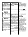
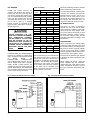
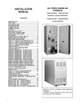
In the upflow position, the heat exchanger support screw shown in the
picture may be removed. This may be
preferable if the furnace rear panel will
be inaccessible after installation. The
screw must be removed if the heat exchanger must be removed from the cabinet. Do not remove this screw if installing
furnace in a horizontal position.
Heat Exchanger Support Screw
Fig. 1: Typical Suspended Application
3
P*HMX furnaces models are assembled
and shipped ready for installation in the
up-flow position. The furnace may be
installed in either of the horizontal positions; warm air discharging left or warm
air-discharging right by following these
steps:
1.
2.
3.
Rotate the furnace 90° to the desired position.
Remove the three nut and washer
sets fastening the oil burner assembly to the furnace. Rotate the oil
burner assembly to be in the normal
upright position.
Re-align the oil burner assembly to
the combustion chamber (fire-pot),
and then secure into place with the
three nut and washer sets.
NON-SUSPENDED INSTALLATION
Maintain clearances to combustibles as
outlined in Table 1. Installation on a
combustible floor requires a clearance of
1 inch. This can be done by using a noncombustible material such as one-inch
thick channel iron or similar material. The
furnace must be supported in such a way
as to not allow twisting or sagging of the
cabinet. Suggestion; as a measure to
prevent fuel oil from accumulating in
locations other than the fire pot, as could
be the case in the event of nozzle drip,
install the furnace with an approximate 2
degree slope from the oil burner casing
towards the fire pot. Use shims made of
noncombustible material.
SUSPENDED INSTALLATION
Refer to Figure 1. Maintain clearances to
combustibles as outlined in Table 1. The
furnace may be suspended by field fabricating a cradle of angle iron and
threaded rod. Secure the furnace with 2
inch minimum slotted angle or equivalent, as shown in Figure 1. The furnace
must be supported in such a way as to
not allow twisting or sagging of the cabinet. Position the supports so as to not
interfere with accessing the burner and
blower compartments. Suggestion; as a
measure to prevent fuel oil from accumulating in locations other than the fire pot,
as could be the case in the event of nozzle drip, install the furnace with an approximate 2 degree slope from the oil
burner casing towards the fire pot.
AIR CONDITIONING
If the furnace is used in conjunction with
air conditioning, the furnace shall be
installed in parallel with or upstream from
the evaporator coil to avoid condensation
in the heat exchanger. In a parallel installation, the dampers or air controlling
means must prevent chilled air from entering the furnace. If the dampers are
manually operated, there must be a
means of control to prevent the operation
of either system unless the dampers are
in the full heat or full cool position. The
air heated by the furnace shall not pass
through a refrigeration unit unless the
unit is specifically approved for such
service.
Generally, a six-inch clearance between
the air conditioning evaporator coil and
the heat exchanger will provide adequate
airflow through the evaporator coil.
The blower speed must be checked and
adjusted to compensate for the pressure
drop caused by the evaporator coil. Refer to Appendix B for recommended wiring and electrical connections of the air
conditioning controls.
COMBUSTION AIR
When a furnace is installed in the full
basement of a typical frame or brick
house, infiltration is normally adequate to
provide air for combustion and draft operation. If the furnace is installed in a
closet or utility room, two (2) ventilation
openings must be provided connecting to
a well ventilated space (full basement,
living room or other room opening
thereto, but not a bedroom or bathroom).
One opening shall be located 6" from the
top and bottom of the enclosure at the
front of the furnace. For furnaces located
in buildings of unusually tight construc4
tion, such as those with high quality
weather stripping, caulking, windows and
doors, or storm sashed windows, or
where basement windows are well
sealed, a permanent opening communicating with a well ventilated attic or with
the outdoors shall be provided, using a
duct if necessary. Size all of the openings and associated ductwork by the
standards provided in the latest Oil Installation Code editions; NFPA 31 in the
United States, CAN/CSA B139 in Canada. Take all fuel burning appliances in
the area into consideration when calculating combustion and ventilation air requirements.
The Model CAS-2B-90E Furnace Boot
manufactured by Field Controls, Inc. may
be used with the furnace to obtain combustion air directly from outdoors. Use of
this device does not alter the need for
ventilation air; however, it does provide a
good direct source of combustion air and
is connected directly to the oil burner.
CHIMNEY VENTING
The chimney must be sized correctly and
be in good repair. If the chimney is oversized, there is a high risk of the flue
gases condensing resulting in damage to
the chimney and other venting parts.
This problem may be corrected by the
use of an appropriately sized chimney
liner.
If
the
chimney
serves
the
P2HMX12F08001 or P3LBX12F08001,
furnace only, the vent should be sized at
4-inch minimum, 5-inch maximum. If the
chimney serves the P3HMX14F10001,
P3HMX20F12001 or P3LBX14F12001
furnace only, the vent should be sized at
4-inch minimum, 6-inch maximum. The
data provided in Table 3 is based on
dedicated venting. If the furnace is to be
co-vented with other appliances, refer to
NFPA 211, Standard for Chimneys, Fireplaces, Vents, and Solid Fuel-Burning
Appliances, NFPA 31, Standard for the
Installation of Oil Burning Equipment or
CAN/CSA B139, Installation Code For
Oil Burning Equipment for correct sizing
information.
NOTE: This furnace is approved for
use with L-Vent.
NOTE: Maximum temperature for LVent is 575°F (300°C).
IMPORTANT: The chimney must be
capable of providing sufficient draft at all
times for the safe removal of the products of combustion.
The chimney should be tested under
“winter” conditions; doors and windows
closed, all other fossil fuel burning appliances on, clothes dryer on, bathroom
fans on, etc. If the chimney cannot overcome the competition for air, it will be
necessary to access the reason for it,
and take corrective action. If the chimney
is found to be sized correctly and in good
repair, it will probably be necessary to reevaluate the availability of combustion
and ventilation air, and take corrective
action.
The flue pipe should be as short as possible with horizontal pipes sloping upward toward the chimney at a rate of one
quarter inch to the foot. The flue pipe
should not be smaller in cross sectional
area than the flue collar on the furnace.
The flue pipe should connect to the
chimney such that the flue pipe extends
into, and terminates flush with the inside
surface of the chimney liner. Seal the
joint between the pipe and the lining. The
chimney outlet should be at least two
feet above the highest point of a peaked
roof. All unused chimney openings
should be closed. Chimneys must conform to local, provincial or state codes, or
in the absence of local regulations, to the
requirements of the National Building
Code.
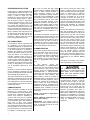
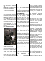
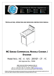
See Figure 2 and Table 2 for common
chimney problems and their remedies.
THE FURNACE MUST BE CONNECTED TO A FLUE HAVING SUFFICIENT DRAFT AT ALL TIMES TO ENSURE SAFE AND PROPER OPERATION OF THE APPLIANCE.
The flue pipe must not be routed through
concealed space, because it must be
visually checked for signs of deterioration during the annual inspection and
servicing. The flue pipe must not pass
through any floor or ceiling, but may
pass through a wall where suitable fire
protection provisions have been installed. In the United States, refer to the
latest edition of NFPA 31 for regulations
governing the installation of oil burning
equipment. In Canada, refer to the latest
edition of CAN/CSA B139 for rules governing the installation of oil burning
equipment.
Fig. 2: Common Chimney Problems
Can be found
by light and
mirror reflecting
conditions in
chimney.
Use weight to
break and dislodge.
Joist protruding
into chimney.
Lowering a light
on an extension
cord.
Must be handled by competent masonry
contractor.
F
Break in chimney lining.
Smoke test build smudge
fire blocking off
other opening,
watching for
smoke to escape.
Must be handled by competent masonry
contractor.
G
Collection of
soot at narrow
space in flue
opening.
Lower light on
extension cord.
Clean out with
weighted brush
or bag of loose
gravel on end
of line.
H
Offset
Lower light on
extension cord.
Change to
straight or to
long offset.
Found by inspection from
basement.
The least important opening
must be closed,
using some
other chimney
flue.
D
E
Table 2: Common Chimney Problems
I
Two or more
openings to the
same chimney.
J
Loose-seated
pipe in flue
opening.
Smoke test.
Leaks should
be eliminated
by cementing
all pipe openings.
K
Smoke pipe
extends into
chimney.
Measurement
of pipe from
within or observation of pipe
by means of a
lowered light.
Length of pipe
must be reduced to allow
end of pipe to
be flush with
inside of tile.
L
Failure to extend the length
of flue partition
to the floor.
By inspection or
smoke test.
Extend partition
to floor level.
M
Loose-fitted
clean-out door.
Smoke test.
Close all leaks
with cement.
Refer to Figure 2
Key
Trouble
A
Top of chimney
lower than surrounding objects
Observation
Extend chimney
above all surrounding objects within 30
feet.
B
Chimney Cap
or ventilator.
Observation
Remove
C
Coping restricts
opening.
Observation
Make opening
as large as
inside of chimney.
5
Diagnostic
Remedy
Obstruction in
chimney
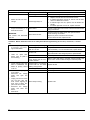
DRAFT REGULATOR CONTROL
This device is used in conjunction with conventional chimney
venting. This control (or draft regulator) automatically maintains
a constant negative pressure in the furnace to obtain maximum
efficiency. It ensures that proper pressures are not exceeded. If
the chimney does not develop sufficient draft, the draft control
cannot function properly. The draft regulator, must be installed
within the same room or enclosure as the furnace, and should
not interfere with the combustion air supplied to the burner. The
control should be located a minimum of 3 flue pipe diameters
from the furnace breeching and installed in accordance to the
instructions supplied with the regulator.
Table 3: Minimum Chimney Base
Temperatures (°F)
Nozzle
Chimney Height (ft.)
11
20
28
36
Chimney Thermal Resistance < R6
0.50
300
400
535
725
0.65
275
340
430
535
0.70
270
330
405
505
0.75
260
320
380
475
0.85
250
300
355
430
1.00
225
300
365
430
Nozzle
Chimney Height (ft.)
11
20
28
36
Chimney Thermal Resistance > R6
0.50
185
200
220
250
0.65
175
185
205
220
0.70
175
185
195
215
0.75
175
185
195
210
0.85
165
185
195
205
1.00
165
185
195
205
< - less than, > - greater than
OIL TANK
Oil storage tanks must be selected and
installed in compliance with applicable
codes; in the United States, NFPA 31,
Standard for the Installation of Oil Burning Equipment, Chapter 2. and in Canada, CAN/CSA-B139, Installation Code
for Oil Burning Equipment, Section 6.
Observe all local codes and by-laws.
In general, the oil tank must be properly
supported and remain stable in both
empty and full condition. The oil tank
must be fitted with vent and supply pipes
to the outdoors. Refer to the abovementioned codes for sizing. The vent
pipe must be no less than 1¼ inches
I.P.S., and terminate with an appropriate
vent cap in a location where it will not be
blocked. The fill pipe must be no less
than 2 inches I.P.S., and terminate with
an appropriate cap in a location where
debris will not enter the fill pipe during oil
delivery.
If located indoors, the tank should normally be in the lowest level, (cellar,
basement, etc.). It must be equipped
with a shut-off valve at the tank outlet
used for the oil supply. The oil tank must
be located as to not block the furnace /
room exit pathway. Observe all clearances specified in the above-mentioned
codes.
6
PIPING INSTALLATION
In the United States, NFPA 31, Standard
for the Installation of Oil Burning Equipment, Chapter 2.
In Canada, the entire fuel system should
be installed in accordance with the requirements of CAN/CSA B139, and local
regulations. Use only approved fuel oil
tanks piping, fittings and oil filters.
Ensure that all fittings used in a copper
oil line system are high quality flare fittings. Do not use compression fittings.
Do not use Teflon tape on any fittings.
Pressurized or gravity feed installations
must not exceed 3 PSIG. Pressures
greater than 10 PSIG may cause damage to the shaft seal. If the height of the
oil stored in a tank above the oil burner
exceeds 11½ feet, it may be necessary
to use a pressure-regulating device approved for this purpose.
The furnace may be installed with a onepipe system with gravity feed or lift. The
maximum allowable lift on a single line
system is 8 feet. Lift should be measured
from the bottom (outlet) of the tank, to
the inlet of the burner. Sizing a single
line system is complex because of the
difficulty estimating the pressure drop
through each fitting, bend and component in the line. In general, keep single
line systems short as possible. 2-stage
oil pumps are not available for either the
P*HMX or P3LBX furnaces. The following chart shows the allowable line
lengths (horizontal + vertical) for single
and two-line oil piping systems. All distances are in feet.
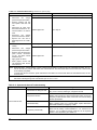
Table 4: Oil Lines
Copper Tubing Oil Line Length (Feet)
Lift
(Feet)
Single-Pipe
Two-Pipe
3/8”
OD
1/2”
OD
3/8”
OD
1/2”
OD
0
53
100
68
100
1
49
100
65
100
2
45
100
63
100
3
41
100
60
100
4
37
100
58
100
5
33
100
55
100
6
29
100
53
100
7
25
99
50
100
8
21
83
48
100
9
17
68
45
100
10
13
52
42
100
12
---
---
37
100
14
---
---
32
100
16
---
---
27
100
18
---
---
22
88
In retrofit applications, where an existing
oil line system is in place, a vacuum
check will help determine the efficacy of
the existing oil line system The vacuum
in a system should not exceed 6” Hg. for
a single pipe system, nor 12” Hg. for a
two-pipe system.
NOTE: The oil burner requires the use of
a bypass plug when converting from
single-pipe to two-pipe oil piping systems. See burner manufacturer’s instructions.
All fuel systems should include an oil
filter between the fuel oil storage tank
and the oil burner. For best results, install the oil filter as close to the burner as
possible. When using an indoor oil tank,
the oil filter may be installed at the tank
downstream from the shut-off valve. If
firing the furnace under the 0.65 gph
rate, a 7 to 10 micron line filter should be
installed as close to the oil burner as
possible.
ELECTRICAL CONNECTIONS
The furnace is listed by the Canadian
Standards Association (CSA). It is factory wired and requires minimal field
wiring. In the United States, the wiring
must be in accordance with the National
Fire Protection Association NFPA-70,
National Electrical Code, and with local
codes and regulations. In Canada, all
field wiring should conform to CAN/CSA
C22.1 Canadian Electrical Code, Part 1,
and by local codes, where they prevail.
The furnace should be wired to a separate and dedicated circuit in the main
electrical panel; however, accessory
equipment such as electronic air cleaners and humidifiers may be included on
the furnace circuit. Although a suitably
located circuit breaker can be used as a
service switch, a separate service switch
is advisable. The service switch is necessary if reaching the circuit breaker
involves becoming close to the furnace,
or if the furnace is located between the
circuit breaker and the means of entry to
the furnace room. The furnace switch
(service switch) should be clearly
marked, installed in an easily accessible
area between the furnace and furnace
room entry, and be located in such a
manner to reduce the likelihood that it
would be mistaken as a light switch or
similar device.
The power requirements for all models:
120 VAC, 1 ∅, 60 Hz., 12A.
Accessories requiring 120 VAC power
sources such as electronic air cleaners
and humidifier transformers may be
powered from the ST9103 EFT. Do not
use the direct drive motor connections as
a power source, since there is a high risk
of damaging the accessories by exposure to high voltage from the autogenerating windings of the direct drive
motor.
Thermostat wiring connections and air
conditioning contactor low voltage connections are shown in the wiring diagrams. Some micro-electronic thermostats require additional controls and wiring. Refer to the thermostat manufacturer's instructions.
The thermostat should be located approximately 5 feet above the floor, on an
inside wall where there is good natural
air circulation, and where the thermostat
will be exposed to average room temperatures. Avoid locations where the
thermostat will be exposed to cold drafts,
heat from nearby lamps and appliances,
exposure to sunlight, heat from inside
wall stacks, etc.
Normal heat anticipator setting: 0.1 A.
For more precise adjustment, the heat
anticipator may be adjusted to the amperage draw of the heating control circuit
as measured between the "R" and "W"
terminals of the thermostat. To reduce
the risk of damaging the heat anticipator,
do not measure circuit without first removing one of the two wires first. To
determine the heating circuit amperage
draw:
1.
Disconnect one of the “R” or “W”
wires from the thermostat terminal.
2.
Connect an ammeter between the
wire and the thermostat terminal to
which it was attached.
3.
Note the amperage reading when
the heating contacts are closed.
(System switch must be on “HEAT” if
so equipped.
4.
Re-connect the thermostat wire. If
the thermostat is serving a combination heating and air conditioning system, pay particular attention to
polarity.
5.
When the thermostat is reconnected
and re-plumbed, adjust the heat anticipator setting to match the observed amperage reading.
CIRCULATING AIR BLOWER
All P*HMX and P3LBX furnace models
are equipped with a direct drive blower
system. Direct drive blower speed adjustments are not normally required in
properly sized extended plenum duct
systems. The motor RPM and air CFM
delivery will vary automatically to accommodate conditions within the usual
range of external static pressures typical
of residential duct systems. Under-sized
duct systems may require a higher
blower speed to obtain a reasonable
system temperature rise. Some older
duct systems were not designed to provide static pressure. They typically feature special reducing fittings at each
branch run and lack block ends on the
trunk ducts. These systems may require
modification to provide some resistance
to the airflow to prevent over- amping of
the direct drive blower motor. Selecting a
lower blower speed may correct this
problem.
Direct drive blower speeds are adjusted
by changing the "hot" wires to the motor
winding connections. Please refer to
wiring diagram in Appendix B or the wiring diagram label affixed to the furnace.
THE NEUTRAL WIRE (normally the
white wire) IS NEVER MOVED TO ADJUST THE BLOWER SPEED.
DO NOT CONNECT POWER LEADS
BETWEEN MOTOR SPEEDS. THE
NEUTRAL WIRE MUST ALWAYS BE
CONNECTED TO THE MOTOR'S DESIGNATED NEUTRAL TERMINAL.
It is possible and acceptable to use a
single blower speed for both heating and
cooling modes. The simplest method to
connect the wiring from both modes is to
use a "piggy-back connector" accommodating both wires on a single motor tap.
It is also acceptable to connect the selected motor speed with a pigtail joined
to both heating and cooling speed wires
with a wire nut. As a safety precaution
against accidental disconnection of the
wires by vibration, it is advisable to secure the wire nut and wires with a few
wraps of electricians tape.
If the joining of the blower speed wiring
is done in the furnace junction box, tape
off both ends of the unused wire.
In the heating mode, the circulating fan
start-up is delayed 45 seconds from the
initial call for heat; 30 seconds from the
start of the oil burner.
7
The circulating fan start-up and shutdown is immediate in the cooling mode.
The heating mode “fan off” delay may be
field adjusted by manipulating the dipswitches. See Figures 3.
Fig. 3: Heating “Blower Off” Timings
DISCONNECT THE POWER SUPPLY
TO THE FURNACE BEFORE OPENING THE BLOWER ACCESS DOOR
TO SERVICE THE AIR FILTER, FAN
AND MOTOR. FAILURE TO SHUT OFF
POWER
COULD
ALLOW
THE
BLOWER TO START UNEXPECTEDLY, CREATING A RISK OF DEATH
OR PERSONAL INJURY.
Do not use the blower speed wires as
a source of power to accessories as
electronic air cleaners and humidifier
transformers. The unused motor taps
auto-generate sufficiently high voltages to damage accessory equipment. Use the terminals provided on
the ST9103 EFT
Do not start the burner or blower fan
unless the blower access door is securely in place.
Additional ST9103 Fan Timer Control
information is in Appendix A, Tables, and
in Appendix B, Wiring Diagrams.
Electrode positioning should be checked
before the first firing of the furnace.
OIL BURNER
Table 5: Nozzles
P*HMX and P*LBX furnaces are
equipped with Beckett AFG Series oil
burners. The oil burner must align properly with the cerafelt fiber chamber (firepot). The cerafelt fiber chamber is initially
quite soft, but hardens and becomes
quite brittle after the first firing. The firepot is held in place by a retaining
bracket; however, it is possible for the
firepot to shift if subjected to rough handling during transit.
OUTPUT
BTU/Hr.
Delavan
58,000
0.50/70°W
0.50/70°SS
0.50/70°Q
73,000
0.65/70°W
0.65/70°SS
0.65/70°Q
79,000
0.70/70°W
0.70/70°SS
0.70/70°Q
BEFORE OPERATING THE FURNACE CHECK BURNER ALIGNMENT
WITH COMBUSTION CHAMBER.
THE END CONE OF THE AIR TUBE
MUST BE CENTRED TO THE ACCOMODATING RING PROVIDED IN
THE DESIGN OF THE COMBUSTION
CHAMBER. ADJUST ALIGNMENT AS
NECESSARY BEFORE THE FIRST
FIRING.
OIL BURNER NOZZLES
P2HMX12F08001 and P3LBX12F08001
furnaces are certified for multiple firing
rates, ranging from approximately 60,000
to
80,000
BTU/hr.
The
P3HMX14F10001,
P3HMX20F12001
and P3LBX14F12001 furnaces are certified for multiple firing rates of approximately 85,000 115,000 BTU/hr. By
changing the oil burner nozzle within the
specific Model Range, and temperature
rise, the furnace may be fired at an ideal
rate for a wide range of structures.
Hago
Stienen
P2HMX12F08001
The electrode porcelains should be free
of cracks, the electrode tips should be
tapered and free of burrs, and the contact rods must be clean and be in firm
contact with the ignition transformer contact springs. The electrodes must not
come into contact with the burner head.
OIL BURNER SET-UP
P3LBX12F08001
57,000
0.50/70°W
0.50/70°SS
0.50/70°Q
75,000
0.65/70°W
0.65/70°SS
0.65/70°Q
79,000
0.70/70°W
0.70/70°SS
0.70/70°Q
P3HMX14F10001 / P3HMX20F12001
87,000
0.75/70°W
0.75/70°SS
0.75/70°Q
100,000
0.85/70°W
0.85/70°SS
0.85/70°Q
118,000
1.00/70°W
1.00/70°SS
1.00/70°Q
P3LBX14F12001
85,000
0.75/70°W
0.75/70°SS
0.75/70°Q
96,000
0.85/70°W
0.85/70°SS
0.85/70°Q
113,000
1.00/70°W
1.00/70°SS
1.00/70°Q
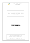
BURNER ELECTRODES
Correct positioning of the electrode tips
with respect to each other, to the fuel oil
nozzle, and to the rest of the burners is
essential for smooth light ups and proper
operation. The electrode tips should be
adjusted to a gap of 5/32”, 1/16” ahead
of the nozzle, 5/16” above the centerline
of the nozzle. The “Z” dimension (front
edge of the burner head to the front face
of the nozzle is 1-1/8 inches.
Fig. 4: Horizontal Smoke Test Port Location
8
NOZZLE
The burner air supply is adjusted to
maintain the fuel to air ratio to obtain
ideal combustion conditions. A lack of air
causes "soft" and "sooty" flames, resulting in soot build-up throughout the heat
exchanger passages. Excess combustion air causes a bright roaring fire and
high stack temperatures resulting in poor
fuel efficiency.
PREPARATIONS:
Drill a ¼” test port in the venting, ideally
at least 2 flue pipe diameters away from
the furnace breeching, if venting horizontally from the furnace, (typically P3LBX)
or from the flue pipe elbow if venting
vertically (typically P*HMX) before reaching the furnace. (see Figures 4 and 5).
The test port will allow flue gas samples
to be taken and stack temperatures to be
measured.
Before starting the burner, check the
burner alignment with the combustion
chamber (fire pot), check that the correct
nozzle is tightened into place, and that
the burner electrodes are properly positioned.
Fig. 5: Vertical Smoke Test Port Location
The Beckett burner bulk air band is
should be closed, and the air shutter
initial setting should be approximately
7.00.
smoke test to ensure that the values
have not changed.
Note A: Locate hole at least 6 inches on
the furnace side of the draft control.
If oily or yellow smoke spots are found
on the smoke test filter paper, it is usually a sign of unburned fuel. This indicates poor combustion. This type of
problem may be caused by excess draft,
excess air, or contaminated fuel. Do not
ignore this indicator.
Note B: Ideally, hole should be at least
12 inches from breeching or elbow.
PROCEDURE:
Start the burner and allow it to run at
least ten minutes. Set the air shutter to
give a good flame visually. The combustion air supply to the burner is controlled
by manipulating the air shutter on the left
side of the burner, and, if necessary, the
bulk air band. To adjust, loosen the bolt
on the movable shutter. Move the shutter
gradually until a good flame (visually)
has been achieved. Re-snug the bolt.
Check the initial draft setting as the furnace warms up. The draft may be measured at the test port. The breech draft
should be approximately - 0.05” w.c. to
obtain an over fire draft reading of - 0.02
inches w.c.
Fig. 6: Checking Over-Fire Draft.
SMOKE TEST NOTE:
STACK TEMPERATURE:
Stack temperature will vary depending
on fuel input, circulating air blower
speed, and burner set up, etc. In general, stack temperature should typically
range between 380°F to 550°F, assuming that the combustion air is approximately room temperature (65°F - 70°F).
In general, lower stack temperature indicates greater efficiency; however, excessively low stack temperature can lead
to condensation forming in the chimney
and / or venting. Sulphur and similar
contaminants in the fuel oil will mix with
condensation to form acids. Acids and
resultant chemical salts will cause rapid
deterioration of the chimney and venting
components, and may attack the furnace.
If the flue gases are below the range, it
may be necessary to slow down the
blower fan. If the flue gases are above
the range, the blower fan may require
speeding up. Stack temperature varies
directly with the system temperature rise.
System temperature rise is the difference
between the furnace outlet temperature
and furnace inlet temperature as measured in the vicinity of the connection between the plenum take-offs and the trunk
ducts. Typical temperature rise values
range between 55°F and 85°F.
Check the oil pump pressure. Standard
operating pressure is 100 PSIG.
After reaching steady state, take a
smoke test. If not indicating a trace, set
the combustion air controls to provide a
trace.
If the venting from the furnace to the
chimney is long, or exposed to cold ambient temperatures, it may be necessary
to use L-Vent as the vent connector to
reduce stack temperature loss to prevent
condensation. The venting should be
inspected annually to ensure that it is
intact.
FURNACE INSTALLATION
SET-UP
The furnace must be set up as the final
step in the installation.
Typically, the CO2 reading will range
from 11.5% to 13.5%.
A) The oil burner must be set up following the procedures outlined above.
After the air adjustments have been
completed, and the air shutter or air adjustment plate has been secured, recheck the over fire draft and take another
B) The
P2HMX1208001
and
P3LBX12F08001 models should operate
within a temperature rise of 60°F to 90°F.
The
P3HMX14F10001,
9
P3HMX20F12001 and P3LBX14F12001
models should operate within a temperature rise of 55°F to 85°F. To determine
the temperature rise, measure the supply
air and return air temperatures when the
furnace has reached steady state conditions. This is the point at which the supply air temperature stops increasing relative to the return air temperature. The
furnace may have to run 10 to 15 minutes to reach steady state conditions.
The measurements may be made with
duct thermometers or thermocouples
used in conjunction with multi-meters
with temperature measurement capabilities.
The return air should be measured at a
point where the thermometer will be well
within the air stream near the furnace
return air inlet. Actual location is not particularly critical; however, avoid locations
where the temperature readings could be
affected by humidifier bypass ducts, the
inside radius of elbows, etc.
The supply air temperature should be
measured at a point where the thermometer will be well within the air stream
near the furnace supply air outlet. Usually, the side mid-point of the supply air
plenum take-off is ideal, providing it is
out of the line of sight to the heat exchanger. If the thermometer is within the
line of sight of the heat exchanger, the
supply air readings may be skewed by
radiant heat from the heat exchanger. If
the plenum take-off is unsuitable, the
supply air temperature may be measured
within the first 18 inches of the first segment of supply air trunk duct.
If the temperature rise is outside the recommended range, it may be adjusted on
direct drive equipped units by selecting
alternate circulation fan motor speeds. If
the temperature rise is too high, speed
the fan up. If the temperature rise is too
low, slow the fan down.
C) Keep in mind that the stack temperature varies directly with the temperature rise. The higher the temperature
rise, the higher the stack temperature will
be, resulting in lower efficiency. The
lower the temperature rise, the lower the
stack temperature will be, which, in some
cases, may allow condensation to form
in the chimney and other vent parts.
D) Test the high limit control to ensure
that it is operating correctly. This may be
done by temporarily removing the circulator fan heating wire or neutral wire.
Turn of electrical power to the furnace
before working with the motor wires. Be
sure to protect any removed wires from
shorting out on metal furnace parts. If the
high limit test is successful, shut off the
electrical power to the furnace, restore
the proper motor wiring. Finally, restore
power to the furnace.
E) Operate the furnace through a
minimum of three full heating cycles.
During this time, check for fuel oil leaks,
gross air leakage from the supply air
ductwork, unusual noises originating
anywhere within the heating system
which may cause some concern or annoyance to the home owner, etc.
F) Be sure that the homeowner is familiar with the furnace. The homeowner
should be aware of the location of electrical circuit breaker or fuse, the location
of any electrical switches controlling the
furnace, the location of the oil tank shutoff valve and how to operate the valve.
The homeowner should be informed
where the oil tank gauge is located and
how to read it.
It would be beneficial to review safety
issues with the home owner, such as the
danger of storing combustibles too close
to the furnace, hanging anything on the
furnace vent pipe, and especially the
dangers of indiscriminately pressing the
burner reset button.
IMPORTANT: Be sure that the home
owner knows where the burner reset
switch is located, and is aware that the
reset switch is not to be activated more
than once without a thorough look for the
cause of the problem, (lack of fuel, etc.).
Be sure that the homeowner knows
when to quit trying to start the furnace
during these conditions and who to call
for emergency service.
MAINTENANCE AND SERVICE
A: Routine Maintenance By Home
Owner
Other than remembering to arrange for
the annual professional servicing of the
furnace by the service or installation contractor, the most important routine service performed by the homeowner is to
maintain the air filter or filters. A dirty
filter can cause the furnace to over-heat,
fail to maintain indoor temperature during
cold weather, increase fuel consumption
and cause component failure.
The furnace filter(s) should be inspected,
cleaned or replaced monthly. The furnace is factory equipped with a semipermanent type filter. If the filter is damaged, replace with filters of the same
size and type.
10
During the routine service, inspect the
general condition of the furnace watching
for signs of oil leaks in the vicinity of the
oil burner, soot forming on any external
part of the furnace, soot forming around
the joints in the vent pipe, etc. If any of
these conditions are present, please
advice your service or installation contractor.
B: Annual Service By Contractor
and fittings. The barometric draft regulator should open and close freely.
All electrical connections should be
checked to ensure tight connections.
Safety controls such as the high limit
controls should be tested for functionality. The fan control functions should be
checked to ensure that all fan speeds
are operating properly.
OPERATING INSTRUCTIONS
Before Lighting
THE Combustion chamber (firepot) IS
FRAGILE. use care when inspecting
and cleaning this area.
The heat exchanger should be inspected
periodically and cleaned if necessary. if
cleaning is necessary, SHUT OFF
POWER TO THE FURNACE and remove the burner. Using a stiff brush with
a wire handle, brush off scale and soot
from inside the drum and flue pipe. To
clean the radiator, remove the round
cover or covers on the inner radiator
access pipes located on the front panel
between the oil burner and the flue pipe.
Rear breech models have a single front
cleanout and front breech models have
two front cleanouts.
A wire brush can be used to loosen dirt
and debris on the inside surfaces of the
radiator. Clean out all accumulated dirt,
soot and debris with a wire handled
brush and an industrial vacuum cleaner.
Replace the clean-out covers.
Most circulating fan motors are permanently lubricated by the motor manufacturer. These motors will have no oil
ports. If the blower motor does contain
oil ports, under normal operating conditions it will not require oiling for the first
two years. Oil sparingly; a few drops in
each oil port with SAE 20 non-detergent
oil. Oiling is most easily done with a
"tele-spout" oiler. This oiler has a long
flexible plastic spout. DO NOT OVERLUBRICATE. Excess oil may result in
premature electric motor failure.
Inspect the blower fan. Clean it if necessary.
Oil Burner Maintenance: Follow the instructions of the oil burner manufacturer.
(See oil burner manufacturer's instructions supplied with furnace). The oil
burner nozzle should be replaced annually. We recommend that the oil filter be
changed on an annual basis.
The venting system should be cleaned
and inspected for signs of deterioration.
Replace pitted or perforated vent pipe
Open all supply and return air registers
and grilles.
Open all valves in oil pipes.
Turn on electric power supply.
To Light Unit
Set the thermostat above room temperature to call for heat. The burner will start.
NOTE: If the furnace has been off for an
extended period of time, it may be necessary to press the RESET button on the
primary combustion control relay, (once
only). If pressing the reset button does
not start the furnace, refer to Appendix
C, Troubleshooting.
45 seconds after the thermostat calls for
heat, (30 seconds after the oil burner
starts), the furnace becomes warm, the
circulation fan will start.
The furnace will continue to run until the
thermostat call for heat is satisfied.
Set the thermostat below room temperature. The oil burner will stop.
The air circulation blower will continue to
run for 60, 90, 120 or 150 seconds after
the oil burner has stopped, depending on
the dip switch settings.
To Shut Down Unit
Set the thermostat to the lowest possible
setting. Set the manual switch (if installed) in the Electrical Power Supply
Line to "OFF".
NOTE: If the furnace is to be shut down
for an extended period of time, close the
oil supply valve to the oil burner.
DO NOT ATTEMPT TO START THE
BURNER WHEN EXCESS OIL HAS
ACCUMULATED, WHEN THE FURNACE IS FULL OF VAPOUR, OR
WHEN THE COMBUSTION CHAMBER
IS VERY HOT. NEVER BURN GARBAGE OR PAPER IN THE FURNACE,
AND NEVER LEAVE PAPER OR RAGS
AROUND THE UNIT.
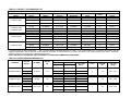
TABLE A-1: BECKETT OIL BURNER SET-UP
FURNACE
MODEL
OUTPUT
BTU/Hr.
P3HMX14F10001
P3HMX20F12001
FLOW
RATE
HEAD
STATIC
PLATE
AF76BO
0.50 / 70°W
100 PSIG
0.50 GPH
F0
3-3/8 in.
73,000
2
AF76BN
0.65 / 70°W
100 PSIG
0.65 GPH
F3
3-3/8 in.
79,000
2
AF76BN
0.70 / 70°W
100 PSIG
0.70 GPH
F3
3-3/8 in.
87,000
2
AF76BZHS
0.75 / 70°W
100 PSIG
0.75 GPH
F4
3-3/8 in.
100,000
AF76BZHS
0.85 / 70°W
100 PSIG
0.85 GPH
F4
3-3/8 in.
118,000
AF76BZHS
1.00 / 70°W
100 PSIG
1.00 GPH
F4
3-3/8 in.
1, 2
AF76BO
0.50 / 70°W
100 PSIG
0.50 GPH
F0
3-3/8 in.
75,000
2
AF76BN
0.65 / 70°W
100 PSIG
0.65 GPH
F3
3-3/8 in.
80,000
2
AF76BN
0.70 / 70°W
100 PSIG
0.70 GPH
F3
3-3/8 in.
85,000
2
AF76BZHS
0.75 / 70°W
100 PSIG
0.75 GPH
F4
3-3/8 in.
AF76BZHS
0.85 / 70°W
100 PSIG
0.85 GPH
F4
3-3/8 in.
AF76BZHS
1.00 / 70°W
100 PSIG
1.00 GPH
F4
3-3/8 in.
57,000
P3LBX12F08001
BECKETT AFG SERIES OIL BURNERS
NOZZLE
PUMP
(Delavan)
PRESSURE
1, 2
58,000
P2HMX12F08001
BURNER
MODEL
P3LBX14F12001
96,000
113,000
1
2
F0 Head required for proper combustion.
Low Firing Rate Baffle required (Beckett Part No. 3708). In the United States, the R. W. Beckett “AFG” Burner may be
equipped with Beckett’s “Inlet Air Shut-Off”, Beckett Part No. AF/A 5861, to increase efficiency. It reduces the amount of air passing through the oil burner, combustion
chamber, breeching, etc. up the chimney between burner cycles.
NOTE: THE USE OF THIS CONTROL CAN OCCASIONALLY CAUSE POST COMBUSTION NOZZLE DRIP.
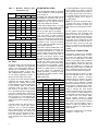
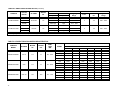
TABLE A-2: DIRECT DRIVE BLOWER SET-UP
BLOWER SET-UP
FURNACE
OUTPUT
BTU/Hr.
BLOWER
MOTOR
HP
58,000
P2HMX12F08001
P3HMX14F10001
P3HMX20F12001
73,000
1/2
0.50 in. w.c.
Speed
Speed
Htg. CFM
1
Range
Low
Med-Low
629 - 972
Med-Low
Med-High
792 - 1223
79,000
Med-High
High
857 - 1324
87,000
Med-Low
Med-High
976 - 1508
Med-High
High
1084 - 1676
118,000
High
High
1279 - 1977
87,000
Low
Low
1106 - 1843
Med-Low
Med-Low
1229 - 2048
Med-High
High
1450 - 2417
100,000
100,000
118,000
11
GT10 DD
COOLING CAPACITY
0.20 in. w.c.
G10 DD
G12-10 DD
1/2
3/4
MOTOR
HP
Clg. CFM
Range
3
1/2
900 - 1150
3
1/2
800 - 1300
5
3/4
1400 - 1870
Tons
2
TABLE A-2: DIRECT DRIVE BLOWER SET-UP (continued)
FURNACE
OUTPUT
BTU/Hr.
BLOWER SET-UP
BLOWER
MOTOR
HP
0.50 in. w.c.
Speed
Speed
Htg. CFM
1
Range
Low
Med-Low
583 - 876
Med-Low
Med-High
707 - 1060
80,000
Med-High
High
819 - 1229
85,000
Low
Low
922 - 1424
Med-Low
Med-Low
1041 - 1609
Med-High
High
1225 - 1894
57,000
P3LBX12F08001
P3LBX14F12001
75,000
96,000
GT10 DD
1/2
G10 DD
1/2
113,000
(1)
COOLING CAPACITY
0.20 in. w.c.
Heating Range values based on temperature rise. Upper values may exceed measured airflow values in Table A-3.
(2)
MOTOR
HP
Clg. CFM
Range
3
1/2
800 - 1200
3
1/2
800 - 1400
Tons
2
Nominal values only.
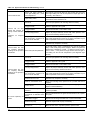
TABLE A-3: DIRECT DRIVE BLOWER CHARACTERISTICS
FURNACE
MODEL
P2HMX12F08001
P3HMX14F10001
P3HMX20F12001
12
BLOWER
GT10
G10
G12-10
MOTOR
HP
1/2
1/2
3/4
MOTOR
FLA
7.7
7.7
12.5
TEMP.
RISE
(∆
∆T)
60° - 90°F
55° - 85°F
45° - 75°F
CFM
SPEED
External Static Pressure – inches w.c.
0.20
0.30
0.40
0.50
0.60
0.70
High
1368
1298
1223
1144
1046
938
Med-High
1318
1256
1178
1108
1007
909
Med-Low
1173
1132
1071
993
909
816
Low
856
833
791
748
692
610
High
1604
1527
1446
1360
1245
1092
Med-High
1507
1425
1338
1270
1171
1035
Med-Low
1172
1146
1119
1064
977
879
Low
810
771
731
690
645
597
High
1957
1911
1846
1797
1729
1658
Med-High
1764
1730
1695
1640
1584
1526
Med-Low
1677
1658
1603
1565
1506
1424
Low
1446
1446
1446
1404
1315
1245
TABLE A-3: DIRECT DRIVE BLOWER CHARACTERISTICS (continued)
FURNACE
MODEL
P3LBX12F08001
P3LBX14F12001
BLOWER
GT10
G10
MOTOR
HP
1/2
1/2
MOTOR
FLA
7.7
7.7
TEMP.
RISE
∆T
60° - 90°F
55° - 85°F
CFM
SPEED
External Static Pressure – inches w.c.
0.02
0.03
0.04
0.05
0.06
0.07
High
1444
1337
1220
1117
1020
911
Med-High
1359
1268
1170
1090
975
844
Med-Low
1063
1034
1005
944
844
730
Low
730
689
688
644
596
486
High
1566
1487
1404
1316
1145
945
Med-High
1487
1404
1339
1245
1036
913
Med-Low
1222
1197
1174
1092
913
809
Low
845
845
809
771
690
596
TIP:
These formulae will assist with the design of the ductwork and the determination of airflow delivery:
CFM =
13
Bonnet Output
. x SystemTemperature Rise)
(1085
SystemTemperature Rise =
Bonnet Output
. x CFM)
(1085
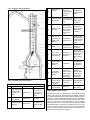
GENERAL DIMENSIONS – P*HMX MODELS
TABLE A-4: GENERAL DIMENSIONS (Inches) – P*HMX MODELS
Cabinet
Plenum Openings
Width
A
Depth
B
Height
C
22
31
49½
Supply Air
DxE
20½ x 20
Flue
Return Air
Side
Bottom
FxG
P2HMX12F08001
14 x 22
14 x 22
Filter
(Perm.)
Ship
Weight
(lb.)
Dia.
Height
H
5
42
16 x 25 x 1
190
46½
16 x 25 x 1
270
P3HMX14F10001 and P3HMX20F12001
22
14
31
58⅛
20½ x 20
14 x 22
14 x 22
6
GENERAL DIMENSIONS – P3LBX MODELS
TABLE A-5: GENERAL DIMENSIONS (Inches) – P3LBX MODELS
Width
A
Cabinet
Length
B
Height
C
22
51½
32
Plenum Openings
Flue
Supply Air
Return Air
Height
Diameter
DxE
FxG
H
P3LBX12F08001
20½ x 18⅝
20½ x 18⅝
Filter
(Perm.)
Ship
Weight
(lb.)
5
26
20 x 20 x 1
240
6
34½
20 x 25 x 1
267
P3LBX14F12001
22
15
51½
41
20½ x 18½
20½ x 18½
APPENDIX B: WIRING DIAGRAM
16
WIRING NOTES
CONTINUOUS FAN OPERATION:
The ST9103 EFT has provisions to run
the blower motor continuously on a
speed lower than the cooling or heating
speeds. On a call for cooling, the fan
motor will switch to cooling speed, and
on a call for heating, the fan will switch to
heating speed, each over-riding the continuous low speed fan.
To obtain continuous low speed fan,
route a 16 gauge stranded, type TEW,
105°C wire from the CONT Terminal on
the ST9103 EFT to the low speed or
medium low speed motor terminal. Both
wire ends will require ¼ inch quick connects, (also known as “Faston” connectors or ¼” spade connectors). For additional control over the continuous low
speed fan circuit, a SPST toggle switch
may be wired in series between the motor terminal and the ST9103 terminal.
The continuous low speed fan operation
operates at 115 vac. Use appropriate
wiring methods to prevent electrical
shock.
NOTE: It is seldom advisable to operate
an electronic air cleaner at the continuous low speed because of the potential
for excess ozone generation.
The HUM terminals provide power to a
line voltage humidifier or humidifier step
down transformer when the oil burner
motor is operating.
THERMOSTAT HEATING
CONNECTIONS:
The thermostat connections “R” and “W”,
or “RH” and “W” connect to the “R” and
“W” screw terminals shown on the left
hand side of Figure 8, on the ST9103
EFT located in the control box mounted
on the right hand side of the vestibule.
Fig. 7:Thermostat Connections
ST9103
TURN OFF ELECTRICAL POWER TO
THE FURNACE WHEN SERVICING OR
ALTERING FURNACE WIRING.
FAILURE TO DO SO MAY RESULT IN
SEVERE PERSONAL INJURY, PROPERTY DAMAGE OR DEATH.
ACCESSORIES:
The ST9103 EFT has provisions for supplying 115 volt power to an electronic air
cleaner (EAC) as well as 115 volts to a
line voltage humidifier or humidifier step
down transformer. Both sets of terminals
are ¼ inch quick connect type, rated at 1
A each.
The EAC terminals provide power to an
electronic air cleaner whenever the heating or cooling speeds are activated.
Power is not provided when the continuous speed is activated. If the electronic
air cleaner must run during continuous
low speed fan operation, wire the EAC
into the furnace L1 terminal.
17
NOTE: All thermostat wires for both
heating and cooling connect to the furnace at this point. A factory installed
wiring harness connects the heating control functions to the R7184 oil primary
control.
Figure 3, page 7, shows the detail of the
timed “Blower Off” dipswitch settings.
Figure 8 shows the dipswitch location
along the bottom edge of the control
board, just above the “Honeywell” label.
R7184 Detailed Sequence of Operation
Power is applied to unit. The R7184 completes a self-diagnostic procedure. If no light or flame is present, and unit passes its selfdiagnostic procedure, the control enters into the idle mode.
Thermostat calls for heat:
A)
B)
Safety check is made for flame (4 second delay).
1)
When flame is not present, the R7184 will apply power to the burner motor and igniter.
2)
When flame is present, the control remains in the idle state.
Unit enters and completes a pre-purge period of 15 seconds, then applies power to the solenoid valve.
C) Control enters the trial for ignition state.
D) Control monitors the burner flame.
1)
When flame is present, the control enters ignition carryover state. (Continues to spark for 10 sec.).
a)
Provides continuous spark after flame is sensed to assure that burner remains lit.
b)
Turns on LED diagnostic light.
c)
Starts carryover timer.
(i)
E)
Flame and call for heat are monitored.
•
If flame is lost and lockout timer has not expired, R7184 will return to trial for ignition state.
•
If flame is lost and lockout timer has expired, R7184 will enter the recycle state.
♦
Recycle timer starts.
♦
Burner motor and igniter and solenoid valve are turned off.
♦
LED diagnostic light flashes slow.
♦
Returns to idle state when recycle timer expires (60 seconds).
Carryover timer expires.
1)
Enters run state.
a)
Igniter turns off.
Combustion continues until thermostat is satisfied, or R7184 detects a loss of flame and enters into Recycle Mode.
F)
18
Thermostat is satisfied - call for heat is terminated:
a)
R7184 shuts off burner motor and solenoid valve.
b)
LED diagnostic light is off.
c)
R7184 returns to idle state.
IDLE STATE
R7184
SEQUENCE of
OPERATION
THERMOSTAT CALLS FOR HEAT
SAFETY CHECK FOR FLAME (5 SEC.)
NO FLAME
FLAME
REMAINS IN IDLE STATE
BURNER MOTOR & IGNITOR START
15 SEC.
SOLENOID VALVE OPENS
LOCKOUT STATE
TRIAL FOR IGNITION
BURNER FLAME MONITORED
NO FLAME
FLAME
•
•
•
CARRYOVER STATE
Provides continuous spark
LED diagnostic light ON
Start Carryover Timer
•
•
•
•
R7184:
Shuts off burner motor
Shuts off igniter
Shuts off Solenoid Valve
Fast Flashes LED Diagnostic
Light
TO EXIT LOCKOUT
PRESS RESET
FLAME LOST
FLAME
CARRYOVER TIMER EXPIRES
FLAME LOST
FLAME
•
RUN STATE
Ignitor turns off.
THERMOSTAT SATISFIED
•
•
•
R7184 SHUTS OFF:
Burner Motor
Solenoid Valve
LED Diagnostic Light
RETURNS TO IDLE STATE
19
RECYCLE TIMER STARTS
FLAME LOST
•
•
•
•
R7184:
Shuts off Solenoid Valve
Shuts off Ignitor
Shuts off Burner Motor
Slow Flashes LED diagnostic light
RECYCLE TIMER EXPIRES
(60 SECONDS
Table C-1: ST9103 DETAILED SEQUENCE OF OPERATION
Mode
Action
System Response
Thermostat calls for heat. ("W"
terminal is energized).
a. ST9103 closes oil primary control T - T connections).
b. Ignition system and R7184 oil primary control start the furnace. Oil flows as
long as the oil primary control senses flame.
c. Burner motor is energized and heat "fan on" delay timing begins. When timing
is complete (30 seconds), the circulator fan is energized at heat speed.
Thermostat ends call for heat.
("W" terminal is de-energized).
a. R7184 oil primary control is de-energized, terminating the burner cycle.
b. Heat "fan off" delay timing begins. Length of delay depends on ST9103 dipswitch settings. When timing is complete, the circulator fan is de-energized.
c. ST9103 returns to standby mode, (Oil primary control and circulator fan are
off, unless continuous fan operation is selected at the thermostat).
Burner fails to light.
a. Oil primary control locks out within lockout timing, (30 seconds).
b. Burner motor is de-energized. (even though thermostat is still calling for
heat).
c. If circulator fan has started, it continues through the selected heat “fan off”
delay period.
Established flame fails.
a. Burner motor is de-energized and oil primary control goes into recycle mode.
b. If the selected heat “fan off” delay timing is longer than the recycle delay timing, the circulator fan continues to run through the next trial for ignition.
Thermostat begins call for cool.
(G and Y terminals are energized).
a. Cooling contactor is energized immediately.
b. Circulator fan is energized at cool speed.
Thermostat ends call for cool.
(G and Y terminals are deenergized).
a. Cooling contactor is de-energized immediately.
b. Circulator fan turns off immediately.
Thermostat begins call for fan.
(G terminal is energized).
a. Circulator fan is energized immediately at cooling speed.
Thermostat ends call for fan.
(G terminal is de-energized).
a. Circulator fan is de-energized immediately.
HEAT
COOL
FAN
Limit switch string opens.
Oil primary control shuts off burner.
Circulator fan is energized immediately at heat speed.
Circulator fan is energized immediately at heat speed.
ST9103 opens oil primary control T - T connections. Circulating fan runs as
long as limit string stays open.
e. If there is a call for cooling or fan, the circulating fan switches from heating to
cooling speed.
Limit switch string closes
(with existing call for heat).
a.
b.
c.
d.
Limit switch string closes (without existing call for heat).
a. Circulator fan turns off when heat “fan off” delay time is complete.
b. Normal operation resumes; ST9103 control is in standby mode awaiting next
thermostat command.
FAN
Continuous circulating fan is
connected.
a. Circulating fan is energized when there is no call for heat, cool, or fan.
b. If fan operation is required by a call for heat, cool, or fan, the ST9103
switches off the continuous fan speed tap before energizing the other fan
speed.
EAC
Electronic Air Cleaner is connected.
• Electronic air cleaner (EAC) connections are energized when the heat or cool
speed of the circulator fan is energized. EAC connections are not energized
when the optional continuous fan terminal is energized.
HUM
Humidity control is connected.
• Humidifier connections are energized when the oil burner motor is energized.
LIMIT
20
a.
b.
c.
d.
ST9103 begins heat “fan off” delay sequence.
Circulating fan turns off after the selected heat “fan off” timing.
ST9103 re-closes oil primary control T - T connections.
Oil primary control is energized, initiating burner light-off.
R7184 LED Diagnostic Light
The LED diagnostic light has several
functions. It indicates the state or mode
in which the oil burner is operating. It will
also indicate fault conditions, and help
determine cad cell resistance while the
burner is operating.
Table C-2: Cad Cell Resistance
Flashes
Resistance in Ohms
1
Less than 400
2
Between 400 - 800
NORMAL CONDITIONS:
3
Between 800 – 1600
The LED diagnostic light will turn on
when the burner enters the carryover
state; the point at which ignition spark is
on, and will remain on through the run
state, where the ignition spark is terminated but the burner continues to fire.
4
Between 1600 - 5000
Troubleshooting
IMPORTANT:
Due to the potential hazard of
line voltage, only a trained, experienced service technician
should perform the troubleshooting procedure.
The LED diagnostic light will turn off at
the end of the burner cycle as the R7184
enters the idle state, and will remain off
until the next heating cycle.
FAULT CONDITIONS:
If the LED diagnostic light is flashing
quickly; 1 Hz (½ second on / ½ second
off), the R7184 is in the lockout state or
in restricted mode. To exit the lockout
state, press the reset button.
If the LED diagnostic light is flashing
slowly; ¼ Hz (2 seconds on / 2 seconds
off), the R7184 is in the recycle state.
This indicates that flame sensing was
lost after the lockout timer expired during
the ignition carryover state. The R7184
will return to the idle state within 60 seconds.
• check the electrode gap and position.
• check the contacts between the oil
primary control and the electrodes.
• check oil supply (tank gauge).
• check the oil nozzle, oil filter, and oil
valves.
• check the piping or tubing to the oil
tank.
• check the oil pump pressure.
CHECK OIL PRIMARY CONTROL AND IGNITOR
If the trouble does not appear to be in
the burner or ignition hardware, check
the oil primary control and the ignitor by
using the following equipment:
PRELIMINARY STEPS:
screwdriver.
Check the diagnostic light for indications
of burner condition. Refer to R7184 LED
DIAGNOSTIC LIGHT section for details.
voltmeter (0 - 150 VAC)
If the LED diagnostic light is off, the cad
cell is not sensing flame.
When simulating a call for heat at the
R7184, disconnect at least one thermostat lead wire from the T1 - T2 terminals
to prevent damage to the thermostat.
Neglecting this procedure may burn out
the heat anticipator of a standard 24 VAC
thermostat, or cause harm to components within a micro-electronic thermostat.
If the LED diagnostic light is on, the cad
cell is sensing flame, or viewing ambient
light.
Before checking the oil primary control,
perform these preliminary checks, (repair
or replace controls as necessary):
The resistance of the cad cell may be
checked while the R7184 is in the run
state by pressing the reset button. The
LED diagnostic light will flash the following code:
• check the power supply; fuse box or
breaker, any service switches, all wiring connections, and burner motor reset button (if equipped).
CAD CELL CONDITION:
• check the limit switches to ensure that
the switch contacts are closed.
insulated jumper wires with both ends
stripped.
Electrical Shock Hazard.
Troubleshooting is done with the system
powered. Be careful to observe all necessary precautions to prevent electrical
shock or equipment damage.
Preliminary Checks:
Make sure that limit switches are closed
and that contacts are clean.
Check for line voltage power on the oil
primary control black and white lead
wires.
Refer to Table C-4 or C-5 for further troubleshooting information.
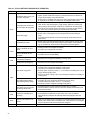
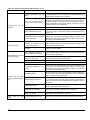
Table C-3: R7184 TROUBLESHOOTING
Condition: Burner motor does not start when there is a call for heat.
Procedure
Status
1.
2.
21
Corrective Action
Check that limit switches are
closed and contacts are
clean. This includes the
burner motor reset button.
N/A
N/A
Check for line voltage power
at the oil primary control.
Voltage should be 120 Vac
between the black and white
lead wires on the oil primary
control.
N/A
N/A
3.
4.
Check indicator light with
burner off, no call for heat (no
flame).
Shield cad cell from external
light.
Indicator light is on.
Cad cell is defective, sees external light, or connections
have shorted. Go to step 4.
Indicator light is off.
Go to step 5.
Indicator light turns off.
Eliminate external light source or permanently shield cad
cell.
•
•
Indicator light stays on.
•
•
5.
Jumper thermostat (T -T)
terminals on R7184
Burner starts.
Trouble is in thermostat circuit. Check thermostat wiring
connections.
If connections are clean and tight, check thermostat wires
for continuity.
•
IMPORTANT
First remove one thermostat lead
wire.
Burner does not start.
Replace cad cell with new cad cell and recheck.
If indicator light does not turn off, remove yellow
leadwires from R7184 and recheck.
If indicator light is still on, replace the R7184
control.
If the indicator light turns off, replace cad cell
bracket assembly.
•
•
•
Disconnect line voltage power and open line
switch.
Check all wiring connections.
Tighten any loose connections and recheck.
If burner still doesn't start, replace R7184
If burner still doesn't start, check the oil burner motor. It
may be seized or burned out.
Condition: Burner starts then locks out on safety with indicator light flashing at 1 Hz rate (½ second on, ½ second off)
Procedure
Status
Corrective Action
1.
2.
3.
Check that the limit switches
are closed and contacts are
clean.
---
---
Check for line voltage power
at the oil primary control.
Voltage should be 120 vac
(nominal)
---
---
Check indicator light with
burner off, no call for heat (no
flame).
Continues on next page
22
Indicator light is on.
Cad cell or controller is defective, sees external light, or
connections are shorted. Go to step 4.
Indicator light is off.
Go to step 5.
Table C-3: R7184 Troubleshooting continued from previous page
Procedure
Status
Indicator light turns off.
4.
Shield cad cell from external light.
Corrective Action
Eliminate external light source or permanently shield cad cell.
4.
5.
Indicator light stays on.
6.
7.
5.
Jumper thermostat (T -T)
terminals on R7184
IMPORTANT
First remove one thermostat
lead wire.
Replace cad cell with new cad cell and recheck.
If indicator light does not turn off, remove cad cell leadwires from R7184 and recheck.
If indicator light turns off, replace cad cell bracket assembly.
If indicator light does not turn off, replace controller.
Burner starts.
Trouble in thermostat or limit circuit. Check thermostat or limit
wiring connections.
Burner does not start.
Disconnect the line voltage power and open line switch.
Check all wiring connections.
Tighten any loose connections and recheck.
If burner does not start, replace R7184
Condition: Burner starts then locks out on safety with indicator light flashing at 1 hz rate (½ second on, ½ second
off)
6.
7.
Reset oil primary control
by pushing in and releasing red reset button.
Listen for spark after
burner turns on (after 2
second delay).
8.
Check indicator light after
flame is established, but
before oil primary control
locks out.
9.
Check cad cell sighting for
view of flame.
Disconnect line voltage
power and open line
switch.
Unplug cad cell and clean
cad cell face with soft
cloth. Check sighting for
clear view of flame. Replace cad cell in socket.
Reconnect line voltage
power and close line
switch.
Start burner.
•
•
•
•
Continues on next page
23
Indicator light stops flashing.
Go to Step 7.
Indicator light continues to
flash at 1 Hz rate.
Verify that the control is not in restricted mode. (See notes at
end of this table.). If not in restricted mode, replace R7184
Ignition is off
Spark ignitor could be defective. Check for line voltage at
ignitor terminals. If line voltage is present, replace R7484.
Ignition is on.
Go to Step 8.
Ignition is on but no oil is
being sprayed into the combustion chamber.
Wait for “Valve ON” delay to complete. Check oil supply, and
oil line valve. Check for filter blockage or seized oil pump.
Indicator light is on until the
control locks out and starts
flashing during lockout.
Replace R7184
Indicator light stays off.
Burner locks out.
Go to step 9.
Go to step 10.
Burner keeps running.
System is OK.
Table C-3: R7184 Troubleshooting continued from previous page
Procedure
Status
Corrective Action
10. Check cad cell.
•
Disconnect line voltage
power and open line switch.
•
Remove existing cad cell
and replace with new cad
cell.
•
Disconnect all wires from
thermostat terminals to ensure that there is no call for
heat.
•
Reconnect
line
voltage
power and close line switch.
•
Expose new cad cell to
bright light such as a flashlight.
Indicator light is on.
Remount control onto burner housing. Go to step 6.
Indicator light is off.
Go to step 11.
11. Check cad cell bracket assembly.
•
Disconnect line voltage
power and open line switch.
•
Remove cad cell wires from
quick connect connectors
on the and leave control
leadwires open.
•
Apply power to device.
•
Place jumper across cad
cell terminals after burner
motor turns on.
Indicator light is on.
Replace cad cell bracket assembly.
Indicator light is off.
Replace R7184.
NOTE: Restricted Mode - (Limited Reset): In order to limit the accumulation of unburned oil in the combustion chamber, the control can be reset only 3 times, after which, the control locks out. The reset count returns to zero each time a call for heat
is successfully completed.
To reset from RESTRICTED MODE: press and hold the reset button for 30 seconds. When the LED flashes twice, the device has reset.
NOTE: Disable function: Pressing and holding the reset button will disable all functions until the button is released. The burner
will restart at the beginning of the normal heat cycle on SAFETY CHECK.
Table C-4: System and General Troubleshooting
Problem
Possible Cause
Remedy
Thermostat not calling for heat.
Check thermostat and adjust. Also, check thermostat for accuracy; if it is a mercury switch type, it might be off level.
No power to furnace.
Check furnace switch, main electrical panel furnace fuse or circuit
breaker. Also look for any other hand operated switch, such as an
old poorly located furnace switch, which was not removed during
furnace replacement.
Thermostat faulty.
Remove thermostat wires from oil primary control terminals T-T.
Place a jumper across T-T. If furnace starts, replace thermostat,
thermostat sub-base (if equipped), or both.
Oil primary control faulty.
Check reset button on oil primary control. Remove thermostat
wires from oil primary control terminals T1 - T2. Check for 24v
across T -T. If no voltage is present, check for 115v to oil primary
control. If 115v is present, go to Table C-3.
Furnace will not start.
Continues on next page
24
Table C-4: System and General Troubleshooting continued
Problem
Possible Cause
Furnace will not start.
Furnace will not start
without first pushing oil
primary control reset button.
(Happens on frequent
basis)
Furnace starts, but cuts
out requiring manually
resetting the oil protector
reset button.
Furnace starts, but cuts
out requiring manually
resetting the oil protector
reset button.
Oil burner sputtering at
nozzle
Continues on next page
25
Remedy
Photo Cell wiring shorted or
room light leaking into photo
cell compartment
Check photo cell (cad cell) wiring for short circuits. Also, check for
room light leaking into cad cell compartment. Repair light leak if
necessary. See Table C-3.
Open safety switch.
Check for open limit or auxiliary limit. Also, check internal wiring
connections; loose connectors, etc.
No fuel oil.
Check fuel oil supply. Check that all hand operated fuel oil valves
are in the open position. Fill oil storage tank if necessary.
Clogged nozzle.
Replace nozzle with high quality replacement. Use rating plate or
Tables in Appendix A as a guide.
Clogged oil filter.
Replace oil tank filter or in-line filter if used.
Low oil pump pressure.
Connect pressure gauge to oil pump. Adjust pump pressure, or
replace oil pump if necessary. Ensure that erratic pressure readings are not caused by defective fuel oil line.
Air getting into fuel oil lines, or
fuel oil line dirty, clogged, or in
some manner defective.
Check fuel oil lines. Replace any compression fittings found with
high quality flared fittings. Check for any signs of oil leaks. Any oil
leak is a potential source of air or contaminants.
Defective burner motor.
Check burner motor. If burner motor is cutting out on over-load,
determine why. Replace if necessary.
Photo Cell (Cad Cell) defective.
If cad cell is dirty, clean it. (Determine why cad cell is getting
dirty). If cad cell is poorly aimed, realign it. NOTE: The photocell
should have a resistance of 100K Ω in absence of light; a maximum of 1500 Ω in the presence of light. Ensure that room light is
not leaking into the cad cell compartment. (see diagnostic light
section).
No fuel oil.
Check fuel oil supply. Check that all hand operated fuel oil valves
are in the open position. Fill oil storage tank if necessary.
Clogged nozzle.
Replace nozzle with high quality replacement. Use rating plate or
Tables in Appendix A as a guide.
Clogged oil filter.
Replace oil tank filter or in-line filter if used.
Low oil pump pressure.
Connect pressure gauge to oil pump. Adjust pump pressure, or
replace oil pump if necessary. Ensure that erratic pressure readings are not caused by defective fuel oil line.
Air getting into fuel oil lines, or
fuel oil line dirty, clogged, or in
some manner defective.
Check fuel oil lines. Replace any compression fittings found with
high quality flared fittings. Check for any signs of oil leaks. Any oil
leak is a potential source of air or contaminants.
Defective burner motor.
Check burner motor. If burner motor is cutting out on over-load,
determine why. Replace if necessary.
Water or contaminants in oil.
Drain fuel oil storage tank, replace fuel oil. (Consult with fuel oil
supplier).
Frozen oil line.
Gently warm oil line. Insulate oil line. (Outdoor piping size may
require increased diameter).
Electrodes out of adjustment or
defective.
Check electrode settings. check electrodes for dirt build-up or
cracks in porcelain.
Poor transformer high voltage
connections or defective transformer.
Check contacts between the igniter and electrodes. If OK, replace
the igniter
Fuel oil filter clogged.
Replace fuel oil storage tank filter and / or fuel oil in-line filter.
Defective oil pump.
Check burner motor / fuel oil pump coupling. Check oil pump
pressure. Replace fuel oil pump if necessary.
Fuel oil line partially clogged or
contains air.
Bleed air from oil line. If problem persists, replace oil line.
Table C-4: System and General Troubleshooting continued
Problem
Excessive fuel oil consumption.
Too much smoke.
Soot building up on blast
tube (end coning).
Furnace will not warm
home to desired temperature.
Home does
evenly
not
Continues on next page
26
heat
Possible Cause
Remedy
System temperature rise too
high.
System temperature rise ideally should not exceed 85°F. Check
for clogged air filters. Check blower fan for excess dirt build-up or
debris. Speed up blower fan if necessary.
Poor “fan off” delay timing selection, (fan stops too soon).
Check “fan off” delay timing setting. Use a duct thermometer in
the supply air plenum take-off or first few inches of the supply air
trunk duct. Ideally, the fan will shut off at a temperature of 90° 100°F. Manipulate the dip switch settings to come as close as
possible to this “fan off” temperature.
Fuel oil leak.
Check fuel oil line for leaks. Repair or replace if necessary.
Stack temperature too high.
Check stack temperature. Stack temperatures will normally range
from 350° to 450°F. Check draft regulator. Draft should be set to
0.02 in. w.c.
Thermostat improperly adjusted
or in poor location.
Check thermostat heat anticipator setting against measured amperage draw. Increase heat anticipator setting if necessary. If the
thermostat is being influenced by drafts, sunlight, duct work, etc.,
relocate to more suitable location.
Insufficient combustion air adjustment at oil burner, or improper draft pressure.
Adjust the oil burner combustion air band and draft regulator to
gain the highest practical CO2 or lowest practical O2 content in the
flue gases. See Burner Set Up.
Heat
exchanger
clogged.
Check for soot build-up in heat exchanger flue passages, especially in the outer radiator.
partially
Poor alignment between oil
burner blast tube and fire pot.
Check alignment. blast tube should be centered with fire pot
burner opening. Oil burner head should be ¼ inch back from the
inside surface of the fire pot.
Flame impingement caused by
Incorrect nozzle angle.
Check nozzle size and angle. (See Appendix A). Check distance
from head to inside surface of the fire pot.
Defective fire-pot
Check fire-pot. Repair or replace.
Airflow blocked or dirty air filter.
Clean or replace air filter.
Thermostat adjustments or location.
Check thermostat heat anticipator setting against measured amperage draw. Increase heat anticipator setting if necessary. If the
thermostat is being influenced by drafts, sunlight, duct work, etc.,
relocate to more suitable location.
Insufficient airflow.
Check all dampers. Open closed dampers including registers in
unused rooms. Check system temperature rise. If temperature
rise is too high, speed up blower fan.
Defective high limit control.
Test high limit function of all limit switches. Use a duct thermometer to assess accuracy of limit control. Check for obstructions to
airflow around limit switch bi-metal elements. Replace control if
necessary.
Under-sized nozzle.
Check nozzle. If problem is not caused by air flow problems, use
larger nozzle, if permitted by rating plate.
Blower fan motor stopping intermittently on overload.
Check blower fan motor amperage draw. Check motor ventilation
ports, clean if necessary. Replace motor if necessary.
Burner motor stopping intermittently on overload.
Check burner motor. Replace if necessary.
Improper distribution of heat.
This is not likely to be a furnace problem. Balance duct system.
Table C-4: System and General Troubleshooting continued
Problem
Supply air temperature
too hot.
Supply air temperature
too cool.
Supply air temperature
too cool during first moments of furnace cycle.
Air Filter Locations
P3LBX Models
P*HMX Models
27
Possible Cause
Remedy
Airflow blocked or dirty air filter.
Clean or replace air filter.
Insufficient airflow.
Check all dampers. Open closed dampers including registers in
unused rooms. Check system temperature rise. If temperature
rise is too high, speed up blower fan.
Excess airflow.
Check system temperature rise. Slow down blower fan if necessary.
Excessive duct losses.
Check supply air ductwork. Seal leaky joints and seams. Insulate ductwork if necessary.
Excessive duct losses.
Check supply air ductwork. Seal leaky joints and seams. Insulate ductwork if necessary.
REPAIR PART LIST – P3HMX14F10001 & P3HMX20F12001
ITEM
1
2
3
4
5
6
7
7A
7B
8
8A
9
10
11
12
13
14
14A
14B
15
15A
15B
15C
16
ITEM
28
DESCRIPTION
Assembly. Left Side Panel (Tan)
Assembly, Right Side Panel (Tan)
Assembly, Rear Panel (Tan)
Assembly, Blower Division Panel
Base Panel Assembly
Inner Front Panel Assembly
Primary Limit Control (180o ) (Upper)
Primary Limit Control (180o ) (Lower)
Blower Access Door (Tan)
Door Handle
Front Door Panel (Tan)
Top Panel (Tan)
Heat Exchanger Assembly
Firepot Bracket Assembly
Replacement Combustion Chamber
Rear Panel Baffle
Left Side Panel Baffle
Right Side Panel Baffle
Oil Burner Mounting Plate Assembly
Gasket, Inspection Door (RH)
Gasket, Inspection Door (LH)
Gasket, Inspection Door (Center)
Gasket, Pouch
DESCRIPTION
16A
17
18
19
20
20A
21
22
22A
23
24
25
26
26A
26B
26C
26D
26E
26F
26G
26I
26J
26K
Gasket, Flue Pipe
Gasket, Clean-out Cover (2 Req’d)
Retainer, Clean-out Gasket (2 Req’d)
Cover, Clean-out (2 Req’d)
Frame, Filter
Filter Frame End Support
Filter, Air (16 x 25 x 1 Permanent)
Box, Junction
Cover, Junction Box
Blower Housing and Wheel
Blower Wheel
Motor, Blower
Motor Mount Band
Motor Mount Arms (3 Req’d)
Capacitor, Blower Motor (10MFD)
Capacitor, Blower Motor (20MFD)
Capacitor Strap
Capacitor Insulator
Blower Side Rails (2 Req’d)
Wire Harness, Blower Motor
Wire Harness, Fan Timer Board
Wire Harness, Transformer
Wire Harness, Supply
Wire Harness, Limit to Limit
REPAIR PART LIST – P3LBX12F08001A & P3LBX14F12001A
ITEM
1
2
3
4
5
6
7
7A
8
8A
8B
9
10
11
12
13
14
15
16
16A
16B
16C
17
18
19
20
21
22
23
29
DESCRIPTION
Panel Assembly, Left Side (Tan)
Panel Assembly, Right Side (Tan)
Panel, Upper Rear (Tan)
Panel Assembly, Blower Division
Panel Assembly, Base
Panel, Inner Front
Door, Blower Access (Tan)
Handle, Door
Panel, Front Door (Tan)
Bezel, Logo
Label, Logo
Panel, Top (Tan)
Heat Exchanger Assembly
Bracket Assembly, Firepot
Chamber, Replacement Combustion
Baffle, Rear
Panel Baffle, Left Side
Panel Baffle, Right Side
Mounting Plate Assy., Oil Burner
Gasket, Inspection Door (RH)
Gasket, Inspection Door (LH)
Gasket, Inspection Door (Center)
Gasket, Pouch
Gasket, Clean-Out Cover (Flue Pipe)
Collar, Flue Pipe (2 Req’d)
Cover, Clean-Out
Gasket, Clean-out Cover
Filter, Air (20 x 20 x 1, Permanent)
Filter, Air (20 x 25 x 1, Permanent)
Panel, Control
ITEM
24
25
26
27
28
29
30
31
32
33
34
34A
34B
34C
34D
34E
34F
34G
35
35A
35B
35C
35D
35E
35F
35G
35H
DESCRIPTION
Cover, Control Panel
Wire Harness, Blower Direct Drive
Wire Harness, Fan Timer Board
Wire Harness, Transformer and Supply
Board, Fan Timer
Transformer
Limit Control (BOF, 140o F)
Limit Control (BOF, 160o F)
Regulator, Draft (5”)
Burner, Oil
Motor, Oil Burner
Pump, Oil, (Cleancut)
Igitor, Solid State
Control, Primary Combustion
Tube Combination, Air
Retention Head, Flame
Nozzle (0.70 gph/70 o W
Nozzle (1.00 gph/70o W
Blower Assembly, Complete
Housing, Blower and Wheel
Wheel, Blower
Motor, Blower
Mount Arms, Motor (3 Req’d)
Run Capacitor, Motor (10MFD/370VAC)
Strap, Capacitor
Blower Feet (LH)
Blower Feet (RH)
REPAIR PART LIST – P2HMX12F08001
ITEM
1
2
3
4
5
6
6A
6B
7
7A
7B
8
8A
9
10
11
12
13
14
14A
14B
15
15A
15B
15C
16
16A
17
18
19
20
20A
21
22
30
DESCRIPTION
Assembly. Left Side Panel (Tan)
Assembly, Right Side Panel (Tan)
Assembly, Rear Panel (Tan)
Assembly, Blower Division Panel
Base Panel Assembly
Inner Front Panel Assembly
Aux. LImit Control (150 Deg. Up Pos.)
Aux. LImit Control (140 Deg. Low Pos.)
Inner Front Panel Assembly
Primary Limit Control (180 Deg.)
Limit Support Assembly
Blower Access Door (Tan)
Door Handle
Front Door Panel (Tan)
Top Panel (Tan)
Heat Exchanger Assembly
Firepot Bracket Assembly
Replacement Combustion Chamber
Rear Panel Baffle
Left Side Panel Baffle
Right Side Panel Baffle
Oil Burner Mounting Plate Assembly
Gasket, Inspection Door (RH)
Gasket, Inspection Door (LH)
Gasket, Inspection Door (Center)
Gasket, Pouch
Gasket, Flue Pipe
Gasket, Clean-out Cover (2 Req’d)
Retainer, Clean-out Gasket (2 Req’d)
Cover, Clean-out (2 Req’d)
Frame, Filter
Filter Frame End Support
Filter, Air (16x25x1 Permanent)
Box, Junction
ITEM
22A
23
24
25
26
26A
26B
26C
26D
26E
26F
26G
26I
26J
27
28
28A
29
29A
29B
29C
29D
29E
29F
29G
30
31
DESCRIPTION
Cover, Junction Box
Blower Housing and Wheel
Blower Wheel
Motor, Blower
Motor Mount Band
Motor Mount Arms (3 Req’d)
Capacitor, Blower Motor (10MFD)
Capacitor, Blower Motor (20MFD)
Capacitor Strap
Capacitor Insulator
Blower Side Rails (2 Req’d)
Wire Harness, Blower Motor
Wire Harness, Fan Timer Board
Wire Harness, Transformer
Wire Harness, Supply
Board, Fan Timer
Box, Control
Transformer (120/24V.- 40VA.)
Assembly, Oil Burner
Motor, Oil Burner
Pump, Oil
Head, Flame Retention
Combination, Air Tube
Relay, Protector
Ignitor, Oil Electronic
Nozzle (0.50 gph / 70o W )
Nozzle (0.70 gph / 70o W )
Nozzle (0.85 gph / 70o W )
Nozzle (1.00 gph / 70o W )
Elbow, Flue Pipe (5” Dia.)
Elbow, Flue Pipe (6” Dia.)
Regulator, Draft (5”)
Regulator, Draft (6”)
REPLACEMENT PART CONTACT INFORMATION
This is a generic parts list. To request a complete parts list, refer to the contact information below:
• Call Consumer Relations at 1-877-874-7378. Follow the instructions to contact the department and/or
representative that can assist you.
• Visit our website at www.source1parts.com for the following information:
1. Search for a part or browse the catalog.
2. Find a dealer or distributor.
3. Customer Service contact information.
a. Click on the “Brand Links” button
b. Click on the “Customer Service” button
• You can contact us by mail. Just send a written request to:
York International
Consumer Relations
5005 York Drive
Norman, OK 7306
31
NOTES
Subject to change without notice. Printed in U.S.A.
Copyright by Unitary Product Group 2003. All rights reserved.
Unitary
Products
Group
5005
York
Drive
035-17473-001 Rev. A (0503)
Supersedes Nothing
Norman
OK
73069