1
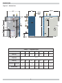
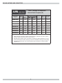
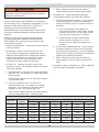
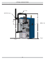
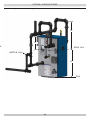
CEG-E GAS-FIRED STEAM BOILERS COLUMBIA COMPANY Main offices and Factory: Pottstown, PA Models CEG075EID CEG112EID CEG150EID CEG187EID CEG225EID CEG262EID CEG299EID INSTALLATION, OPERATION & MAINTENANCE MANUAL MODEL CEGEID Electronic Intermittent Ignition Manufactured by: ECR International, Inc. 2201 Dwyer Avenue, Utica NY 13501 web site: www.ecrinternational.com P/N# 240009938, Rev. A [12/2012] DIMENSIONS Figure 1 - Dimensions A 25" Depth C Safety Relief Valve 2" NPT 2" NPT ½" NPT Plug 16⅝" 2" NPT B 2" NPT 29" 12⅜" 5½" 13½" Floor Table 1 - Physical Data Models 075 112 150 187 225 262 299 Width (A) 10 7/8" 14 1/8" 17 3/8" 20 5/8" 23 7/8" 27 1/8" 30 3/8" 35 7/8" Height (B) Depth (C) Gas Connection Size (G) Flue Diameter 28 3/8" 28 3/8" 29 3/8" 30 3/8" 30 3/8" 30 3/8" 30 3/8" ½ NPT ½ NPT ½ NPT ¾ NPT ¾ NPT ¾ NPT ¾ NPT 5" 5" 6" 7" 7" 7" 7" 2 BOILER RATINGS AND CAPACITIES Table 2 Ratings and Capacities Natural Gas & Propane (LP) Boiler Model Number Input MBH (1) Heating Capacity MBH (1) CEG075EID 75 CEG112EID Net AHRI Rating (2) Steam, MBH Steam, Sq. Ft. AFUE, % No. of Sections Vent Pipe Size 62 47 195 82.2 3 5" 112 93 70 292 82.4 4 5" CEG150EID 150 125 94 391 82.6 5 6" CEG187EID 187 156 117 488 82.8 6 7" CEG225EID 225 188 141 587 83.0 7 7" CEG262EID 262 219 164 685 83.2 8 7" CEG299EID 299 250 188 782 83.4 9 7" Heating Capacity and AFUE are based on DOE (Department of Energy) test procedures. 1. Input rating for sea level to 2,000 ft. above sea level. Altitudes over 2000 ft. above sea level, reduce input rate 4% for every 1000 ft. 2. Net AHRI steam ratings shown are based on a piping and pickup allowance of 1.333. Consult manufacturer before selecting a boiler for installations having unusual piping and pickup requirements, such as intermittent system operation, extensive piping systems, etc. 3 TABLE OF CONTENTS Important Safety Information....................... 5 Introduction Locating the Boiler ...................................... 6 Boiler is designed for use in closed heating systems where all steam is returned as condensate and make-up water is minimal. Boiler is not designed for or intended for use in open systems using 100% make-up water. Hydronic Piping .......................................... 8 Fresh Air for Combustion ............................12 Prior to Installation Chimney and Vent Pipe Connection ..............13 • Verify correct boiler for type of gas being used natural or propane. See Rating Plate. Vent Damper Operation ..............................15 Gas Supply Piping ......................................16 • Verify boiler size and dimensions. See Figure 1 and Table 1, page 2. Electrical Wiring ........................................17 • Verify ratings and capacity data for natural gas. See Table 2. Operating Instructions................................18 Operating Your Boiler .................................19 Installation Requirements Checking and Adjusting ..............................20 • Supply boiler with correct gas (natural or propane), fresh air for combustion, and suitable electrical supply. • Connect boiler to adequate venting and piping systems. • Provide boiler with properly located and adjusted thermostat. Installation of boiler in building under construction, use precaution to insure clean combustion air supply during construction process. Airborne particulate from construction materials can clog burner ports and cause incomplete combustion and sooting. Complete all steps for safe and proper heating system operation. Start-up Cleaning ......................................22 General Maintenance .................................23 Troubleshooting .........................................24 Wire Diagrams ..........................................25 Optional Hydronic Piping.............................28 KEEP THIS MANUAL NEAR BOILER RETAIN FOR FUTURE REFERENCE GAS FIRED STEAM BOILERS Information and specifications outlined in this manual in effect at the time of printing of this manual. Manufacturer reserves the right to discontinue, change specifications or system design at any time without notice and without incurring any obligation, whatsoever. 4 IMPORTANT SAFETY INFORMATION General Installation shall conform to requirements of authority having jurisdiction or in absence of such requirements to the National Fuel Gas Code, Boiler and venting installation shall be completed by qualified agency. ANSI Z223.1/NFPA 54. ! WARNING Where required by authority having jurisdiction, installation shall conform to Standard for Controls and Safety Devices for Automatically Fired Boilers, ANSI/ASME CSD-1. Controls can be added to make this boiler CSD-1 compliant. Check with your local codes for requirements. Fire, explosion, asphyxiation and electrical shock hazard. Improper installation could result in death or serious injury. Read this manual and understand all requirements before beginning installation. Become familiar with symbols identifying potential hazards. Requirements for Commonwealth of Massachusetts: Boiler installation must conform to Commonwealth of Massachusetts code 248 CMR which includes but is not limited to installation by licensed plumber or gas fitter. This is the safety alert symbol. Symbol alerts you to potential personal injury hazards. Obey all safety messages following this symbol to avoid possible injury or death. ! DANGER ! WARNING Indicates a hazardous situation which, if not avoided, WILL result in death or serious injury. Installing or venting a boiler or any other gas appliance with improper methods or materials could result in death or serious injury due to fire or to asphyxiation from poisonous gases such as carbon monoxide which is odorless and invisible. ! WARNING Indicates a hazardous situation which, if not avoided, could result in death or serious injury. ! CAUTION Indicates a hazardous situation which, if not avoided, may result in minor or moderate injury. ! WARNING Fire, explosion, asphyxiation hazard. Keep boiler area clear and free from combustible materials, gasoline and other flammable vapors and liquids. NOTICE Used to address practices not related to personal injury. Modification, substitution or elimination of factory equipped, supplied or specified components could result in death or serious injury. 5 LOCATING THE BOILER Locating the Boiler 1. Select level location as centralized with piping system, Figure 2 - Minimum Clearances To Combustible Construction 6” (152mm) and as near chimney as possible. 2. Place crated boiler at selected location. Remove all crate material. Please recycle responsibly. View from top of boiler ! WARNING Fire hazard. Do not install boiler on combustible flooring or carpeting. Failure to follow these instructions could result in death or serious injury. on non-combustible floors only. For installation on combustible flooring, special base must be used. (See Replacement Parts Manual.) 4. Use metal shims under boiler base legs for final leveling if needed. 5. Install boiler in location that permits satisfactory combustion of gas, proper venting, and maintenance of ambient temperature at safe limits under normal conditions of use. Boiler location should not interfere with proper circulation of air. Introduce outside air if normal infiltration does not provide necessary air.“Fresh Air for Combustion” on page 12. 6. Notify owner to keep air passages free of obstruction. Ventilating and combustion air must enter boiler room without restrictions. Table 3 Minimum Clearance Dimensions Top 6" Rear 6" Control Side 7" Opposite Side 6" Front Flue/Vent Connector Near Boiler Piping Boiler Opposite Side 7” (178mm) 3. Do not install boiler on carpeting. For installation Control Side Rear 6” (152mm) Front ALCOVE Figure 3 - Draft Hood Installation Screw Alcove 6" 1/2" 7. Install boiler so automatic gas ignition system components are protected from water (dripping, spraying, rain, etc.) during appliance operation and service. Draft Hood Draft Hood Installation ! WARNING Asphyxiation, carbon monoxide hazard. Failure to follow these instructions could result in improper combustion and possible leakage of combustion products into the living space. Top and side panels not shown for clarity. 1. Slide draft hood over flue collector. 2. Through holes in jacket top, secure with 1 or 2 screws, Follow directions given in Figure 3. Attach draft diverter, and blocked vent switch. Mount vent damper. See "Connecting Vent Damper and Vent Connector" page 13. See Wiring Diagrams pages 26 and 27. based on boiler size. 6 LOCATING THE BOILER ! DANGER Figure 4 - Pressuretrol Assemly Burn, scald hazard. Pressuretrol must be installed by a qualified service agency in accordance with manufacturer’s instructions, all applicable codes and requirements of authority having jurisdiction. Failure to follow the information in these instructions exactly will result in death or serious injury. Qualified service agency is responsible for proper installation. A Pressuretrol Assembly Installation Instructions: See Figure 4. 1. Attach pressuretrol assembly (A) to site glass assembly, using proper pipe sealant. 2. Remove pressuretrol cover. 3. Route wire harness through black plastic bushing (B). 4. Attach two wires. Wires are not polarity sensitive, can place on either terminal. 5. Replace pressuretrol cover. B 7 HYDRONIC PIPING ! WARNING Burn or Scald Hazard. Discharge line shall be installed to relief valve outlet connection to avoid burns, scalding, or water damage due to discharge of steam and/or hot water during operation. Discharge line shall: • Connect to safety valve outlet. Piped down to safe point of disposal. Check local codes for maximum distance from floor or allowable safe point of discharge. • Pipe size be of equal to or greater than of safety valve outlet over entire length of discharge line. • Have no intervening shutoff valve between safety valve and discharge to atmosphere. Do not plug or place any obstruction in discharge line. • Terminate freely to atmosphere where any discharge will be clearly visible and at no risk of freezing. • Allow complete drainage of valve and discharge line. • Install safety valve with spindle in vertical position. • Do not install shutoff valve between boiler and safety valve. • Support safety valve discharge piping. • Be short and straight as possible. • Terminate with plain end, not threaded. • Constructed of material suitable for exposure to temperatures of 375° F (191°C); or greater. Refer to local codes and appropriate ASME Boiler and Pressure Vessel Code for additional installation requirements. Figure 5 - Safety Valve Safety Valve Discharge Piping Check local codes for maximum distance from floor or other allowable safe point of discharge 6" Above Floor 8 HYDRONIC PIPING 5. Recommended near boiler piping for gravity return Consider near boiler piping as part of the boiler for proper water level control and to produce dry steam. systems is shown in Figure 8 page 11. For gravity return systems, bottom of lowest steam carrying pipe, dry return or end of steam main, must be at least 28” above normal water level line on left side of boiler. 6. Equip all boilers in gravity return systems with Hartford Loop as shown in Figure 6a and 6b page 10. 7. Piping vertical risers from boiler to header, risers must be minimum of 24" high above water line. Correct near boiler piping is crucial to proper operation of boiler and heating system. Follow these recommendations carefully. 1. Place boiler in selected location as near chimney as possible. 2. Install safety valve. Figure 5 and Warning on Page 8. • Install union, if used, close to safety valve outlet. 8. Steam riser(s) and header shall be 2" pipe. • Install elbows close to safety valve outlet and downstream of union (if used). 9. Equalizer line shall be minimum 1-1/2" pipe size. 10. Near boiler piping shall include 2" tee with female 3. Boiler is equipped with two 2" supply connections and adapter and cap located on supply line as shown for skimming (i.e. surface blow-down). 11. For pumped return systems, follow condensate pump or boiler feed pump manufacturer’s instructions for proper installation and hookup. See Table 4 and Figure 7 page 11. 12. Connecting cold water supply to water inlet valve, verify clean water supply is available. When water supply is from well or pump, install sand strainer at pump. two 2" return connections, one each on both left and right sides of boiler. Plug unused connections with furnished 2" plug and 2 x ¾ " bushing for drain valve. 4. When using both supply tappings to pipe system as shown in Figure 6b , Page 10. • Fit headers with header offsets, swing joints, or equip with expansion joints, so thermal expansion and contraction of header does not damage boiler. Do not weld headers. • Place system takeoffs from header between equalizer and riser to header nearest equalizer. System takeoffs must never be between two risers. If steam main goes in two directions, place two takeoffs from header, one for each main. Table 4 - Steam Flow Rates (Gross) 9 Sections Flow Rates LBS/HR 3 63.4 LBS/HR 4 94.7 LBS/HR 5 126.8 LBS/HR 6 158.1 LBS/HR 7 190.2 LBS/HR 8 221.5 LBS/HR 9 252.8 LBS/HR HYDRONIC PIPING Figure 6a - Recommended Near Boiler Piping Using One Supply Tapping Main Vent Sections Risers Headers Equalizers 3 2" 2" 1½ 4 2" 2" 1½ Header 28" 24" Cap To Skimmer Tee Water Line 2" Hartford Loop Close Nipple 24" Equalizer 1½" For Alternate Piping Configurations Floor See Page 28 and 29 Figure 6b - Recommended Near Boiler Piping Using Two Supply Tappings Main Vent Header Sections Risers Headers Equalizers 5 (2) 2" 2" 1½ 6 (2) 2" 2" 1½ 7 (2) 2" 2½" 1½ 8 (2) 2" 3 1½ 9 (2) 2" 3 1½ 28" Cap To Skimmer Tee 24" Hartford Loop 2" Water Line Close Nipple Equalizer 1½" 24" For Alternate Piping Configurations Floor See Pages 28 and 29 10 HYDRONIC PIPING Figure 7 - Recommended Near Boiler Piping For Pumped Return Systems Figure 8 - Recommended Near Boiler Piping For Gravity Return Systems 11 FRESH AIR FOR COMBUSTION ! WARNING C. Refer to National Fuel Gas Code for opening requirements between connected indoor spaces. Air openings to combustion area must not be obstructed. Follow instructions below, to maintain adequate combustion air • All Outdoor Air. Provide permanent opening(s) communicating directly or by ducts with outdoors. A. Two Permanent Opening Method. Provide opening commencing within 12 inches of top and second opening commencing within 12 inches of bottom of enclosure. Provide combustion air and ventilation air in accordance with the section “Air for Combustion and Ventilation,” of the National Fuel Gas Code, ANSI Z223.1 / NFPA 54, or applicable provisions of local building codes. Provide make-up air where exhaust fans, clothes dryers, and kitchen ventilation equipment interfere with proper operation. Direct communication with outdoors or communicating through vertical ducts. Provide minimum free area of 1 in² per 4 Mbh of total input rating of all appliances in enclosure. National Fuel Gas Code recognizes several methods of obtaining adequate ventilation and combustion air. Requirements of the authority having jurisdiction may override these methods. Communicating through horizontal ducts. Provide minimum free area of 1 in² per 2 Mbh of total input rating of all appliances in enclosure. • Engineered Installations. Must be approved by authority having jurisdiction. B. One Permanent Opening Method. Provide opening commencing within 12 inches of top of enclosure. Provide minimum clearance of 1 inch on sides/back and 6 inches on front of boiler (does not supersede clearance to combustible materials). • Mechanical Air Supply. Provide minimum of 0.35 cfm per Mbh for all appliances located within space. Additional requirements where exhaust fans installed. Interlock each appliance to mechanical air supply system to prevent main burner operation when mechanical air supply system not operating. C. Refer to National Fuel Gas Code for additional requirements for louvers, grilles, screens and air ducts. • All Indoor Air. Calculate minimum volume for all appliances in space. Use a different method if minimum volume not available. • Combination Indoor and Outdoor Air. Refer to National Fuel Gas Code for application information. A. Standard Method. See Table 5 for space with natural gas boiler only. Use equation for multiple appliances and/or propane. Room Volume is greater than 50 cubic feet multiplied by Total Input [Mbh] B. Known Air Infiltration Rate. See Table 5 for space with boiler only. Use equation for multiple appliances. Do not use an air infiltration rate air changes per hour (ACH) greater than 0.60. Room volume is greater than 21 cubic feet divided by ACH (air changes per hour) x Total Input [Mbh] Table 5 - Minimum Room Volume, Indoor Air Only* Known Air Infiltration Rate Method (Air Changes Per Hour) Input Mbh Standard Method 0.1 0.2 0.3 0.4 0.5 0.6 75 3750 15750 7875 5250 3938 3150 2625 112.5 5625 23625 11813 7875 5906 4725 3938 150 7500 31500 15750 10500 7875 6300 5250 187 9350 39270 19635 13090 9818 7854 6545 225 11250 47250 23625 15750 11813 9450 7875 262.5 13125 55125 27563 18375 13781 11025 9188 299 14950 62790 31395 20930 15698 12558 10465 * Table values based on boiler only. Add volume for any additional appliances. 12 CHIMNEY AND VENT PIPE CONNECTION 4. Boiler is equipped with factory wired harness that plugs ! WARNING Installing or venting a boiler or any other gas appliance with improper methods or materials could result in death or serious injury due to fire or to asphyxiation from poisonous gases such as carbon monoxide which is odorless and invisible. 5. 6. 7. Boiler and venting installations shall be performed in accordance with "Venting of Equipment", of the National Fuel Gas Code, ANSI Z223.1/NFPA 54, or applicable provisions of the local building codes. 8. 9. 10. Chimney Inspection Chimney must be clean, right size, properly constructed and in good condition. into vent damper. Connect thermostat to orange and white wires marked 24 volt thermostat on boiler. Vent pipe must be same size as flue outlet collar. Slope pipe up from boiler to chimney not less than 1/4” per foot. Run pipe as directly as possible with as few elbows as possible. Do not connect to fireplace flue. End of vent pipe must be flush with inside face of chimney flue. Horizontal run should not be longer than 3/4 the chimney height (HT). See Figure 9 page 14. Vent Pipe • Fasten sections of vent pipe with 3 sheet metal screws at each joint to make piping rigid. • Support horizontal portions of vent system to prevent sagging. • Use stovepipe wires or metal strapping every 5’ to support pipe from above. • Vent pipe through crawl space, use double wall vent pipe. • Vent pipe passing through combustible wall or partition, use ventilated metal thimble. Thimble should be 4" larger in diameter than vent pipe. Installation must conform to requirements of the authority having jurisdiction or, in absence of such requirements, to the National Fuel Gas Code, ANSI Z223.1/NFPA 54. See Figure 9, page 14. Connecting Vent Damper and Vent Connector Vent or vent connector shall be Type B or metal pipe having resistance to heat and corrosion not less than that of galvanized sheet steel not less than No. 26 gauge. See Table 1 for size of vent (flue opening). 1. Position furnished vent damper on top of flue outlet NOTICE collar. Fasten damper securely to flue outlet collar with sheet metal screws. • Verify 1/2 square inch (approximately 3/4" diameter) hole in damper blade is plugged using plug supplied with vent damper. Minimum Vent Pipe Clearance - Wood and other combustible materials must not be closer than 6” from any surface of single wall metal vent pipe. Listed Type B vent pipe or other listed venting systems shall be installed in accordance with their listing. • Verify damper blade has clearance to operate inside of diverter. • Do not modify draft diverter or vent damper. 2. Install vent damper to service only single boiler for Removing Existing Boiler from Common Venting System which it is intended. • Damper position indicator shall be in visible location following installation. When an existing boiler is removed from a common venting system, the common venting system is likely to be too large for proper venting of the appliances remaining connected to it. At the time of removal of an existing boiler, the following steps shall be followed with each appliance remaining connected to the common venting system placed in operation, while the other appliances remaining connected to the common venting system are not in operation. 1. Seal any unused openings in the common venting system. 2. Visually inspect the venting system for proper size and horizontal pitch and determine there is no blockage or restriction, leakage, corrosion and other deficiencies which could cause an unsafe condition. • Locate damper so it is accessible for servicing. Optional - damper may be installed in horizontal or vertical position as close to flue outlet as possible. • Horizontal installations. See Figure 10, page 15. • Alternate installations see steps below. See Figure 11 page 15. A. Do not install vent damper on vent pipe curve. B. Do not run wires near high temperature surfaces. Use stand-off brackets if necessary. 3. Damper must be in open position when appliance main burners are operating. 13 CHIMNEY AND VENT PIPE CONNECTION 3. Insofar as is practical, close all building doors and 4. 5. 6. 7. windows and all doors between the space in which the appliances remaining connected to the common venting system are located and other spaces of the building. Turn on clothes dryers and any appliance not connected to the common venting system. Turn on any exhaust fans, such as range hoods and bathroom exhausts, so they will operate at maximum speed. Do not operate a summer exhaust fan. Close fireplace dampers. Place in operation the appliance being inspected. Follow the lighting instructions. Adjust thermostat so appliance will operate continuously. Test for spillage at the draft hood relief opening after 5 minutes of main burner operation. Use the flame of a match or candle, or smoke from a cigarette, cigar or pipe. After it has been determined that each appliance remaining connected to the common venting system properly vents when tested as outlined above, return doors, windows, exhaust fans, fireplace dampers and any other gas-burning appliance to their previous conditions of use. Any improper operation of the common venting system should be corrected so the installation conforms with the National Fuel Gas Code, ANSI Z223.1/NFPA 54. When resizing any portion of the common venting system, the common venting system should be resized to approach the minimum size as determined using the appropriate tables in Chapter 13 of the National Fuel Gas Code, ANSI Z223.1/NFPA 54. Vent connectors serving appliances vented by natural draft shall not be connected into any portion of mechanical draft systems operating under positive pressure. 14 Figure 9 - Typical Masonry Chimney Requirements VENT DAMPER OPERATION Check vent damper and all flue product carrying areas of boiler annually for deterioration from corrosion or other sources. If you see corrosion or other deterioration, contact your service agent for repairs. Check vent damper operation as follows: 1. When boiler is off, check vent damper positions indicator points to closed position. See Figure 12. 2. Turn thermostat or controller up to call for heat and check vent damper indicator points to open position See Figure 12. 3. Turn thermostat or controller down again and check damper position indicator returns to closed position. 4. Return thermostat to desired position. Figure 10 - Horizontal Installation Horizontal Installation Flow NO YES To BoilerVent Damper To Chimney Vent Damper Flow ! WARNING Actuator may be installer in any position. To Boiler Asphyxiation or burn hazard. Improper operation of vent damper may result in serious injury or death due to fire or to asphyxiation from poisonous gases such as carbon monoxide which is odorless and invisible. NO Install vent damper with actuator to sides of vent only. Do not mount above or below vent. To Chimney Inspect vent damper at least once a year by trained service technician. YES Figure 11 - Alternate Vent Damper Installation Caution: Do not install Vent Damper within 6" (152mm) of combustible material Manual Operation of Vent Damper • Place vent damper in open position to permit burner operation by using “HOLD DAMPER OPEN” switch, located on damper controller. Do Not Install Here Install Damper Here • Thermostat controls burner firing as before, while damper remains open. • DO NOT turn damper open manually, motor damage will result. • Set switch to “AUTOMATIC OPERATION” to close vent damper during burner off cycle. • For further information, and for vent damper troubleshooting guide, refer to manual packaged with vent damper. Chimney Boiler Water Heater Figure 12 - Vent Damper Position Indicator ROTATION OPEN CLOSED Damper Closed Flue Gas Flow ROTATION OPEN CLOSED Flue Gas Flow Damper Open Showing Open and Closed Positions 15 GAS SUPPLY PIPING ! CAUTION ! WHAT TO DO IF YOU SMELL GAS • Do not try to light any appliance. Fire Hazard. Do not use matches, candles, open flames, or other methods providing ignition source. Failure to comply will result in death or serious injury. • Do not touch any electrical switch; do not use any phone in your building. • Immediately call your gas supplier from a neighbor’s phone. Follow gas supplier’s instructions. Leak Check Gas Piping Pressure test boiler and gas connection before placing boiler in operation. Avoid excessive pressure that could damage pressure regulators, valves, or meters. • Pressure test at 1/2 psig (3.5 kPa) or less. Isolate boiler from gas supply system by closing manual gas shutoff valve. • Locate leakage using gas detector, noncorrosive detection fluid, or other leak detection method acceptable to authority having jurisdiction. Do not use matches, candles, open flames, or other methods providing ignition source. • Correct leaks immediately and retest. • If you cannot reach your gas supplier, call the fire department. General • Use piping materials and joining methods acceptable to authority having jurisdiction. In absence of such requirements National Fuel gas Code, ANSI Z223.1/ NFPA 54. • Size and install gas piping system to provide sufficient gas supply to meet maximum input at not less than minimum supply pressure. See Table 6. Table 6 Natural Gas Propane Min. Supply Pressure 5" w/c 11" w/c Max. Supply Pressure 13.5" w/c 13.5" w/c Manifold Pressure 3.5" w/c 10.5" w/c DANGER Figure 13 - Gas Piping At Boiler • Support piping with hooks straps, bands, brackets, hangers, or building structure components to prevent or dampen excessive vibrations and prevent strain on gas connection. Gas valve will not support piping weight. • Use thread (joint) compound (pipe dope) suitable for natural and liquefied petroleum gas. • Install field sourced manual main shutoff valve, ground joint union, and sediment trap upstream of gas valve. See Figure 13. Propane Installation ! WARNING Fire, explosion, asphyxiation hazard. Verify boiler is equipped with propane gas orifices and gas valve is configured for propane. Failure to follow these instructions may result in serious injury or death. • Connections by licensed propane dealer only. • Use two stage regulator provided by propane supplier. • Have propane supplier check piping. 16 ELECTRICAL WIRING Thermostat Installation 1. Install thermostat on inside wall per manufacturer's ! WARNING Electrical shock hazard. Turn OFF electrical power supply at service panel before making electrical connections. Failure to do so could result in death or serious injury. instructions. 2. NEVER install thermostat on outside wall. 3. Do not install thermostat where it will be affected by drafts, hot or cold pipes, sunlight, lighting fixtures, televisions, fireplace, or chimney. NOTICE Label all wires prior to disconnection when servicing controls. Wiring errors can cause improper and dangerous operation. Verify proper operation after servicing. 4. Check thermostat operation by raising and lowering thermostat setting as required to start and stop burners. 5. Instructions for final adjustment of thermostat see manufacturer's instructions. Electric Power Supply Electrically bond boiler to ground in accordance with requirements of authority having jurisdiction. Refer to National Electrical Code, ANSI/NFPA 70. Electronic Thermostats A. Some electronic thermostats may lose their memory or shut down. With probe type low water cutoff, this may occur each time low water cutoff detects low water condition. If this is the case, an isolation relay is required for thermostat circuit. See Figure 17 page 25. B. Some electronic thermostats are not acceptable for use with steam systems, check manufacturer suggested use. Line Voltage Connections A. Provide individual 120V, 15 amp circuit (recommended) with fused disconnect or service switch as required by authority having jurisdiction. B. Locate a shut-off switch at the boiler. C. Connect 120V electrical supply to primary leads on 24 volt transformer. Securely fasten with wire nuts. 17 OPERATING INSTRUCTIONS For Your Safety Read Before Operating 1. STOP! Read the safety information on this page. ! WARNING 2. Set the thermostat to lowest setting. 3. Turn off all electric power to the appliance. 4. This appliance is equipped with an ignition device which If you do not follow these instructions exactly, a fire or explosion may result causing property damage, personal injury or loss of life. automatically lights the pilot. Do not try to light the pilot by hand. Figure 14 - Gas Valve • This appliance is equipped with an ignition device which automatically lights burner. Do NOT try to light this burner by hand. • Before operating smell all around appliance area for gas. Be sure to smell next to floor because some gas is heavier than air and will settle to the floor. • Use only your hand to turn the gas shutoff valve. Never use tools. If valve will not turn by hand, do not try to repair it, call a qualified service technician. Force or attempted repair may result in fire or explosion. GAS CONTROL KNOB SHOWN IN "ON" POSITION • Do not use this appliance if any part has been under water. Immediately call a qualified service technician to inspect appliance and to replace any part of control system and any gas control which has been under water. 5. Remove front panel. 6. Rotate the gas control knob clockwise to“OFF”. 7. Wait five (5) minutes to clear out any gas. Then smell for gas, including near the floor. If you smell gas, STOP! Follow “B” in the safety information on this page If you don’t smell gas, go to next step. ! CAUTION 8. Rotate the gas control knob counterclockwise WHAT TO DO IF YOU SMELL GAS • Do not try to light any appliance. 9. 10. 11. 12. • Do not touch any electrical switch; do not use any phone in your building. • Immediately call your gas supplier from a neighbor’s phone. Follow gas supplier’s instructions. • If you cannot reach your gas supplier, call the fire department. to “ON.” Replace front panel. Turn on all electric power to the appliance. Set thermostat to desired setting. If the appliance will not operate, follow the instructions “To Turn Off Gas To Appliance” and call your service technician or gas supplier. To Turn Off Gas To Appliance 1. Set the thermostat to lowest setting. 2. Turn off all electric power to the appliance if service is to be performed. 3. Push in gas control knob slightly and turn clockwise to “OFF” Do not force. 18 OPERATING YOUR BOILER Thermostat ! WARNING A. Set thermostat to desired room temperature. B. Set thermostat to lower setting if heat is not required C. System is self-checking. If failure of any component system will not operate or will go into safety lockout. D. On call for heat, each component must function properly to permit operation. E. Turn thermostat to lowest setting for one minute and back to normal setting to reset on safety lockout. Burn Hazard. Never run water into a hot empty boiler. Failure to follow these instructions could result in death or serious injury. Filling System With Water Steam heating systems boiler is partially filled with water. Fill boiler to correct level for proper system operation. Correct water level is about halfway up glass water level gauge as marked on boiler jacket. 1. Close boiler drain valve. 2. Open valves at top and bottom of glass water level gauge. 3. Open fill valve. Allow water to run into boiler. 4. Continue to fill boiler until water reaches indicated water line about halfway up glass gauge. Water Level • Normal water level is 24" above the floor as shown on left side of boiler. • Determine water level when boiler is off and cold, when all water in the system is inside the boiler and return piping below water line, and everything above water line is air, no steam. • When boiler is making steam, water level drops two to three inches below normal water line. 19 CHECKING AND ADJUSTING Adjust Pilot Burner Figure 15 - Pilot Burner Pilot flame should surround 3/8” to 1/2” of pilot sensor. See Figure 15. To adjust Flame. 1. Remove screw cover over pilot adjusting screw. See Figure 14. 2. Insert small screwdriver and adjust flame as needed. Turn screw counterclockwise to increase flame, clockwise to decrease. 3. Replace screw cover over pilot adjusting screw. Main Burners • Main burners do not require primary air adjustment and are not equipped with primary air shutters. • Main burner flames form sharp blue inner cones in softer blue outer mantel, with no yellow. Remain still when observing main burner flames. • Check main burner orifices, burner throat and flame ports for dust and lint obstruction if flame appearance is not correct. • Remove rollout shield if necessary to observe main burner flames. See Figure 16. Figure 16 - Main Burner • Replace rollout shield after observation. Gas Valve Safety Shutdown Test 1. Test ignition system safety shutoff device after placing boiler in operation. 2. Boilers equipped with intermittent ignition, with main burners firing, disconnect ignition cable from intermittent pilot control box. Gas valve will shut off main burners. 3. TURN OFF ELECTRIC POWER to boiler before reconnecting ignition cable, to prevent electric shock. 20 CHECKING AND ADJUSTING Adjust Steam Pressure Control Checking Controls • Steam pressure limit control (pressuretrol) shuts off gas to main burners when steam pressure in boiler reaches cut-off setpoint (i.e. sum of cut-in and differential setpoints). Low Water Cut-Off A. Turn off power to boiler or turn thermostat down to lowest setting. B. Drain water to below visible bottom of water gauge glass. Turn power on and turn thermostat to call for heat. C. Gas valve opens for approximately 15 seconds (time delay on probe type LWCO), gas valve will close and red indicator illuminates on LWCO. D. When water is restored, it waits 30 seconds before reactivating burner circuit. • Burners refire when steam pressure drops to cut-in setpoint. • System pressure requirements are based on size and condition of pipes, and load. • Cut-in setting of pressuretrol should never be less than twice system pressure drop for good system operation. A. In typical single family residence with clean onepipe heating system and cast iron radiation, cut-in is usually set at minimum setting, i.e. 1/2 psi. Boiler Equipped With Optional VXT-24 Water Feeder E. Continue thermostat call for heat after low water cut off recognizes low water condition. F. One minute time delay, water feeder starts feeding water to boiler. G. Feeder feeds for one minute, and then goes into another one minute waiting period. H. Cycle of alternately waiting and feeding will repeat until the water level in boiler rises and makes contact with probe, satisfying water feeder and igniting burners. • Steam radiation is sized based on square feet of equivalent direct radiation (EDR). This is based on steam pressure in the radiator of just less than 2 psi. • Set differential adjustment at 1 psi, i.e. steam pressure required in radiators. Results in cut-off setpoint of 1½ psi. • Larger systems or other types of systems such as two pipe systems, or systems with convectors or fan coil units, pressuretrol settings need to be determined on system-by-system basis. • In either case, one and two inches of water should be visible in glass gauge when both water feeder is satisfied, and burners are allowed to ignite. • Cut-in setpoint is determined by system pressure drop to furthest radiator or terminal unit. Double system pressure drop as safety factor, resulting in the rule cut-in setting should never be less than twice system pressure drop. • Time delays in feed cycles are designed to prevent boiler from flooding due to slow return lines. • To check pressure limit, run boiler until pressure reaches system demand. Turn pressure screw and drop pressure setting until boiler shuts down. This shows the pressure limit is operating properly. • Differential setpoint is steam pressure required at terminal heating units. Boiler will now operate in correct pressure range. It maintains enough steam pressure to send steam out to furthest radiator, and not go over optimum steam pressure required at the radiators. • Refer to control manufacturer’s instructions for more information. Check Thermostat Operation Thermostat set above temperature indicated on thermometer, boiler should ignite. Verify thermostat turns boiler off when room temperature reaches selected setting and starts boiler operating when room temperature falls few degrees. Set thermostat for desired temperature. Conditions in your home and location of thermostat will govern this setting. 21 START-UP CLEANING 7. Following final blow-down, allow boiler to cool. ! WARNING • Add fresh water slowly up to normal water line. Following service procedures must be performed by qualified service agent. Boiler owner shall not attempt these steps. Failure to do so could result in death or serious injury. • Start burners. • Maintain at least 180°F for 15 minutes to remove dissolved gasses from fresh water. • Shut off burners. It is very important to clean a new steam boiler after it has been installed and put into continuous operation. This must be done to remove any accumulation of oil, grease, sludge, etc., that may have be present in system. These substances may cause boiler water to foam and surge, producing an unsteady water line, throwing water into steam header, and possibly preventing steam generation. Follow skimming and blow-down steps in order to remove contaminants. 8. Allow system to operate for one week to give majority of system dirt a chance to work its way back to boiler. • Check water in gauge glass. Gauge glass should be dry above water line. • Water line should not bounce more than one inch when boiler is steaming. • If you see water droplets carrying over from top of gauge glass, or excessive bouncing of water line, boiler needs further cleaning. • Take water sample and boil it on stove to see if it foams. If it does, this indicates boiler needs to be cleaned. Skimming and Blow-down ! WARNING Burn Scald Hazard. Water temperatures in excess of 125°F. Failure to follow these instructions could result in death or serious injury. NOTICE Clean water with no additives is essential to proper operation of your boiler and heating system. Boiler cleaners and chemical cleaning, if used and not rinsed properly, may be harmful to the system. New boilers must be skimmed at time of installation to remove threading oil and other impurities that float on surface of water. 1. Remove cap from skimmer female adapter tee and pipe to floor drain or bucket. See Figures 6a and 6b page 10. Raise water level to skimmer tapping. 2. Fire burners to maintain water temperature of 180200°F. 3. Feed water to boiler to maintain water level. Adjust water feed rate to maintain continuous flow of 1 gallon per minute. Do not allow boiler to steam. 4. Continue skimming until water runs clear. This may take several hours. 5. Drain boiler completely to remove any foreign material. 6. Fill boiler to water line. • Fire burners, allow normal steam pressure to build up. If cleaning is necessary, repeat skimming and blow-down procedure above. A long skim will be all you need to clean the boiler. In more troublesome cases it may be desirable to flush the system while, in very extreme cases, it may be necessary to chemically clean and flush heating system. Consult boiler manufacturer before introducing any chemicals into boiler. Check water level frequently. Be sure top and bottom valves on gauge are always open so actual water level is shown at all times. • Run connection from boiler drain valve to safe discharge point outside. • Shut off gas burners, open drain valve, allow all of water in boiler to drain out. • Close drain valve. • Allow boiler to cool, slowly refill boiler to water line. • Repeat this step as many times as necessary until blow-down water is clear. 22 GENERAL MAINTENANCE Low Water Cut-Off Boiler Water Treatment Other Than Cleaners Low Water Cut-Off interrupts electrical current to burner when water line in boiler drops to low level. Check Low Water Cut-Off monthly to verify it is providing proper protection. See “Checking and Adjusting” on page 21. Remove Low Water Cut-Off probes beginning of each heating season for inspection and cleaning. More cleaning may be required on boilers requiring frequent additions of make up water. In steam systems where system is tight, free from leaks, and all steam is returned to boiler as condensate, amount of make up water is small. Water treatment is generally not required. In steam systems with less than 90% of steam being returned as condensate, or with very hard or corrosive make up water, treatment may be desirable. Follow recommendations of your local boiler water treatment specialist. Boiler Flue Passages and Burners Foaming, Priming, or Surging These terms are used to describe fluctuating water line when water leaves boiler with steam. It is caused by any combination of following: 1. Threading oil and organic matter in boiler water. Follow instructions under “Start-up Cleaning.” 2. Faulty quick vents that do not release air until sizeable pressure is built up - if old style, replace - if dirty, clean until you can easily blow through valve. 3. Adjustment of steam limit control to wide differential increases difficulty if quick vents are old style, slowreleasing type or dirty. Always set steam limit control differential as low as possible. 4. Soap and chemicals in boiler water cause extreme surging. Boiler cleaners and chemical cleaning additives are not recommended. If used and not rinsed properly, may be harmful to the system. Beginning of heating season visually check pilot and main burner flames. See page 20. Recommend you have flue passages, burner adjustment, and operation of controls checked once each year by trained Service Technician. Before start of each season or whenever system has been shut down for some time, check system, boiler and vent pipe for leaks. Vent Pipe Check vent piping at lease once a season. Verify vent pipe connections to chimney are secure and no obstructions are present. If vent piping shows sign of leaking, replace it immediately. Safety Valve See Manufacturer's Instructions. Cleaning Boiler Flue Passages and Burners 1. Remove burners, pilot, vent pipe, top and front jacket panels. Remove hold-down nuts and bolts from flue collector. 2. Use putty knife to cut through silicone. Lift flue collector off boiler sections. Remove old silicone material. 3. Clean passageways between sections with flue brush. Remove dirt from bottom of boiler and from between sections by vacuuming. 4. Verify all flame ports in burners are open and clear. Shake or blow out loose dirt in burners. 5. Apply generous bead of 400°F RTV silicone to four mounting surface flanges of flue collector. Mount flue collector on heat exchanger. Tighten nuts and bolts. 6. Seal front edge and four corners of flue collector to heat exchanger with silicone sealant. 7. Use flashlight to verify there are no gaps in silicone seal. 8. Install draft diverter, vent damper, vent pipe, and jacket top and front cover. 9. Reassemble all parts. 10. Check tightness of pilot connections and condition of burner flames after reassembly. See Figures 15 and 16. 23 TROUBLESHOOTING You may avoid inconvenience and service calls by checking these points before you call for service. ! CAUTION WHAT TO DO IF YOU SMELL GAS • Do not try to light any appliance. • Do not touch any electrical switch; do not use any phone in your building. • Immediately call your gas supplier from a neighbor’s phone. Follow gas supplier’s instructions. • If you cannot reach your gas supplier, call the fire department. Symptom System Not Heating or Not Giving Enough Heat Burner is Noisy Possible Cause What To Do Thermostat is not set correctly Reset thermostat above room temperature. Thermostat not operating Inspect and replace thermostat batteries, if necessary. Contact service technician. Burner is not operating properly Inspect flame. If yellow, burner is not getting enough air. If blue and noisy and seems to lift off burner, burner is getting too much air. Contact service technician. No electric power to boiler Verify electric power supply circuit is “ON”. Contact your service technician to verify over current protection. Controls out of adjustment Reset according to instructions. Radiators not heating Inspect steam air vents for proper operation. Contact service technician to inspect for faulty steam traps. Poor electrical contact Contact your service technician to inspect all control terminals and wire joints. Chimney flue is blocked Spill switch contacts open, requiring manual reset of spill switch. Contact service technician to inspect and correct chimney problem. Vent damper not operating Consult troubleshooting guide packaged with vent damper. Gas input is incorrect Contact service technician. Not enough ventilation Contact service technician. Walls or Windows Sweating Chimney flue is blocked Contact service technician to inspect and correct, if necessary. Safety valve Dirt on seat Contact service technician. Leaking HAVE SERVICE TECHNICIAN CHECK ANY PROBLEM YOU ARE UNABLE TO CORRECT. 24 WIRE DIAGRAMS Figure 17 - Isolation Relay Wiring For Steam Boilers With Probe Type Low Water Cut Off And Using An Electronic Thermostat - Optional Figure 18 - Water Feeder Connection - Optional Optional water feeder connection. • Connect feeder N to terminal 2. • Connect feeder H to terminal 1. • Connect "FEED" or "W" to terminal A. • For water feeders with 2 leads, connect feeder common to terminal 2 and feeder hot to terminal A. Note: Use of a solenoid valve or McDonnell & Miller Model 101A water feeder may cause flooding and is not recommended for use with this low water cut-off. 25 WIRE DIAGRAMS (For full-sized Wire Diagrams, see Literature Envelope.) Figure 19 - Wiring Diagram For Boilers With CG 400-2060 Probe Type Low Water Cut-Off BLOCKED VENT SWITCH BLK WHT PRESSURETROL VENT DAMPER BLK WHT CUT IN BLK 9 8 .6 .5 YEL .3 KG/2 CM DIFF 2 0.5 .1 PSI BRN ORG BLK 120V / 24V, 50VA TRANSFORMER G C WHT G N L BLK RED WHT IGNITION MODULE LWCO PROBE MV MV/PV RED PV 24V GND (BURNER) 24V (GND) WHT SENSE BLK WHT JP1 1 P1 P2 SPARK A BURNER FACTORY INSTALLED JUMPER WHT ORG WHT BLU WHT INSIDE BOILER JACKET OUTSIDE BOILER JACKET PROBE JP2 BLK BRN BLK LOW WATER CUT OFF 2 R R 120V AC FIELD CONNECTIONS IN ACCORDANCE WITH NEC / CEC AND LOCAL CODES. USE COPPER CONDUCTORS ONLY YEL C PNK BRN IGNITOR T (W) NEC CLASS 2 LOW VOLTAGE FIELD SUPPLIED THERMOSTAT ROLL OUT SWITCH GAS VALVE PV MV/PV MV WHT T (R) BLK BLU RED WHT BLU GRN P/N: 240009879 Revision: A If any of the original wire as supplied with this appliance must be replaced, it must be replaced with type 105°C Thermoplastic wire or its equivalent. 26 WIRE DIAGRAMS (For full-sized Wire Diagrams, see Literature Envelope.) Figure 20 - Ladder Diagram For Boilers With CG 400-2060 Probe Type Low Water Cut-Off HIGH VOLTAGE CONNECTIONS PER NEC AND LOCAL CODES L N 120V / 24V, 50VA TRANSFORMER R LOW WATER CUT OFF JP1-2 JP1-1 JP1-A JP1-P1 JP1BURNER PROBE JP1-P2 JP2-2 JP2-1 JP2-3 C NEC CLASS 2 LOW VOLTAGE LOW WATER CUT OFF PROBE NOTE: CONNECTOR POSITION 3 IS LABELED 1 ON LWCO CIRCUIT BOARD JP2 MOLEX CONNECTOR VENT DAMPER BLOCKED VENT SWITCH (R) T PRESSURETROL 2 4 1 3 (W) T THERMOSTAT IGNITION MODULE 24V 24V (GND) MV SPARK MV/PV SENSE PV GND (BURNER) GAS VALVE PV GND MV/PV MV 27 SPARK IGNITOR ROLL OUT SWITCH OPTIONAL HYDRONIC PIPING Figure 21 - Counter Flow Steam Systems 2" Pipe Hartford Loop 28" 24" Water Lin 48" 24" Floor Floor 28 OPTIONAL HYDRONIC PIPING Figure 22 - Drop Header for True Swing Joint 28" 24" e Water Line Hartford Loop 24" Floor 29 OPTIONAL PIPING HYDRONIC PIPING 30 Date Service Performed Company Name & Tech Initials Company Address & Phone # SERVICE RECORD 31 Columbia P.O. Box 24202, Baltimore, Maryland 21227