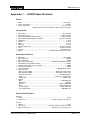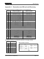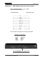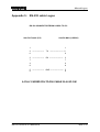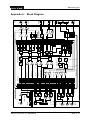
1
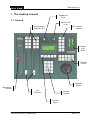
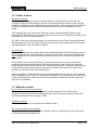
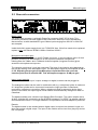
Manual Logos
PART A: INSTALLATION OF THE LOGOS
1
The desktop console ............................................................................................................ 2
1.1 Outlook --------------------------------------------------------------------------------------------------------------------2
1.2 Fader section ------------------------------------------------------------------------------------------------------------3
1.3 Monitor section ----------------------------------------------------------------------------------------------------------3
1.4 Function keys------------------------------------------------------------------------------------------------------------4
1.5 Numeric keypad---------------------------------------------------------------------------------------------------------4
1.6 Transport control section ---------------------------------------------------------------------------------------------5
1.7 Jog / shuttle wheel------------------------------------------------------------------------------------------------------5
2
The rack-unit (D902).............................................................................................................. 6
2.1 Front side connectors--------------------------------------------------------------------------------------------------6
2.2 Rear side connectors --------------------------------------------------------------------------------------------------7
3
LogosTool software .............................................................................................................. 9
3.1 Connect procedure-----------------------------------------------------------------------------------------------------9
3.2 Toolbar ------------------------------------------------------------------------------------------------------------------10
3.3 Tabs----------------------------------------------------------------------------------------------------------------------11
PART B: OPERATION OF THE LOGOS
4
Start-up of the Logos.......................................................................................................... 16
5
Source configuration.......................................................................................................... 17
5.1 Gain ----------------------------------------------------------------------------------------------------------------------17
5.2 Balance or Pan--------------------------------------------------------------------------------------------------------17
6
Microphone adjustments ................................................................................................... 18
6.1 Accessing the menu--------------------------------------------------------------------------------------------------18
6.2 Phantom power -------------------------------------------------------------------------------------------------------18
6.3 HighPass filter ---------------------------------------------------------------------------------------------------------18
6.4 Insert bypass ----------------------------------------------------------------------------------------------------------19
6.5 Compressor / Limiter-------------------------------------------------------------------------------------------------19
6.6 Ducker-------------------------------------------------------------------------------------------------------------------19
6.7 MonitorSel --------------------------------------------------------------------------------------------------------------20
Appendix 1: LOGOS Specifications ........................................................................................ 21
Appendix 2: Description sub-D25 and sub-D9 pinning ....................................................... 22
Appendix 3: UMC Hybrid connection (older version) .......................................................... 23
Appendix 4: UMC Hybrid connection (new version) ............................................................ 24
Appendix 5: RS-232 cable Logos............................................................................................. 25
Appendix 6: Block Diagram ...................................................................................................... 26
Index .............................................................................................................................................. 27
EELA AUDIO Parmentierweg 3
5657 EH Eindhoven, the Netherlands
1
interstage
Phistersvej 31, 2900 Hellerup, Danmark
Telefon 3946 0000, fax 3946 0040
www.interstage.dk
- pro audio with a smile
Rev. 6 (July 2001)
Main v1.43
Manual Logos
1 The desktop console
Headphone
Level
1.1 Outlook
Monitor LSP
Level
Input selection
Channel 2 & 3
PFL / Monitor
Selector
Program
Level
Meter
HeadphonL
evel
Transport
Control
Microphone
Channel
Jogwheel
Shuttle
Line
Channels
Numeric
Keypad
Function
Keys
EELA AUDIO Parmentierweg 3
5657 EH Eindhoven, the Netherlands
2
Rev. 6 (July 2001)
Main v1.43
Manual Logos
1.2 Fader section
Microphone channel
The left fader is always the main microphone channel. If configured as a Controlroom
microphone (factory default setting), the monitor loudspeakers are muted and the red-light
indicator is switched on upon opening the microphone fader. If the microphone is configured
as Studio microphone this indicator will stay dark and the monitor loudspeakers are not
muted.
Upon opening this main microphone fader the monitor will automatically switch to main
output (factory default setting) or a pre-defined source as set in the LogosTool software or on
the desktop console. See also chapter 3.
The LED’s next to the microphone fader are an indication for the build in limiter/compressor.
See paragraph 6.5 for more information about the settings of the compressor/limiter and the
other parameters for the microphone channel.
Line channels
Above each of the two line channel faders are eight pushbuttons with LED indication for the
source input selection. When the fader is closed, a source will be assigned immediately but
only accepted when the other fader does not select that source. In that case the button will
not be active.
An open fader can do only pre-selection. The newly selected source is pre-selected by
pressing a source button and then the LED will start blinking. Upon closing the fader the
newly selected source will become active on that channel directly. If a source is pre-selected
on both faders the channel fader that is closed first will take over that source and the preselection on the other fader will be switched off.
A fader start/stop is coupled to the source and becomes active if the source is selected on a
fader, depending on the LogosTool configuration settings. Pre-selecting a source means that
a fader start/stop will be active also as soon as the fader is closed and opened again (and
the source is activated).
1.3 Monitor section
Level control for the monitor speakers
The monitor level pot can adjust the level for monitor speakers. If the control room
microphone fader is opened the loudspeakers are muted. Using the talkback function will
cause the speakers to dim by approx. 10dB.
Headphone volume
The headphone level pot can adjust the headphone level.
PFL / Monitor selector and talkback
The first eight buttons are used as PFL / Monitor selector, presenting the same sources as
on the input selectors assigned to it.
EELA AUDIO Parmentierweg 3
5657 EH Eindhoven, the Netherlands
3
Rev. 6 (July 2001)
Main v1.43
Manual Logos
Holding the button down longer (long-press function) activates the source dependent set-up
menu. In this menu you can set both gain and balance level for that source.
Pushing the button shortly (short-press function) activates the prefade listening (PFL). The
speakers, headphone and program level meter reproduce the signal of the selected source.
The last two buttons are used for monitoring the Main output and the Talkback function.
Holding the <Main O/P> button longer gives access to the Compressor/Limiter menu of the
main output.
For access to the Microphone setting menu, both <Talk> and <Main O/P> must be
long-pressed together. For more information on this subject see paragraph 3.3.
TALK
MAIN
O/P
Talkback button
The talkback button is a push-to-talk function. The main microphone is used as talkback
microphone; there is no separate talkback-microphone.
The red LED will indicate if this function is active. The talkback-function is allowed with open
fader or not, depending on the device to talk to.
The program level meter
This modulation meter consists of 2*18 LED’s. The character of the meter is a PPM with a
peak-hold function. The meter follows the signal selected by the PFL / Monitor selector. The
external meter connection on the back of the rack always carries the main signal.
1.4 Function keys
Concerning the function keys, 2 buttons always have the same function. The <ESC> button
is for quitting a function and the <ENTER> button for confirming a change. The other keys
follow the function as indicated on the display.
1.5 Numeric keypad
Primary use of the numeric keypad is for manual dialling of telephone hybrids like the
EA915x. The keypad is also used for controlling audio editors. For this purpose, the <2>,
<4>, <6>, <8> and <#> keys are used. At last, the keypad is also used within menus for
changing the menu setting.
EELA AUDIO Parmentierweg 3
5657 EH Eindhoven, the Netherlands
4
Rev. 6 (July 2001)
Main v1.43
Manual Logos
1.6 Transport control section
The Transport control section consists of ten pushbuttons to control audio editors. The Logos
offers support for the following audio editors:
• Dalet
• Digigram X-track
• Netia
The actual function of these buttons depends on
the audio editor used and on the settings made
within this program. In most cases, the user will
be able to configure the function of these buttons.
These keys are active only for the selected
device and will be disabled with open fader.
1.7 Jog / shuttle wheel
The jog / shuttle wheel is used within the set-up menus of the Logos. It is also used when
controlling the audio editors mentioned in the previous paragraph.
EELA AUDIO Parmentierweg 3
5657 EH Eindhoven, the Netherlands
5
Rev. 6 (July 2001)
Main v1.43
Manual Logos
2 The rack-unit (D902)
2.1 Front side connectors
D 902
POWER
DIGITAL I/P
L
INPUT 1
R
HPH 1
Digital input
The most left input of the rack-unit is the AES/EBU and SPDIF tolerant digital input. The
audio modes of this input can be configured in the LogosTool.
Setting the gain level for this input can be done by long-pressing the <Front DIG> key in the
Monitor section, which opens the set-up menu for this input.
Balanced analogue stereo input
These are the two XLR female input connectors right next of the digital input connector. This
analogue input is basically meant for temporary connection of analogue equipment without
remote control, e.g. portable recorders. The audio modes can be configured with the
LogosTool.
Setting the gain level for this input can be done by long-pressing the <Front I/P> key in the
Monitor section, which opens the set-up menu for this input.
Headphone connector
The headphone connector is a ¼ inch jack connector. Level control for the headphone is
done on the desktop console.
Power On switch / LED
On the right side of the unit are the Power On switch and an indication LED. If the unit is
switched on the red indicator will light. A blinking LED will indicate the Program Mode of the
Logos or an operation fault indication (see also Part B of this manual).
EELA AUDIO Parmentierweg 3
5657 EH Eindhoven, the Netherlands
6
Rev. 6 (July 2001)
Main v1.43
Manual Logos
2.2 Rear side connectors
Mains supply
The mains inlet connector is a Neutrik PowerCon connector (NAC 3FCA, blue). This
connector provides a safe and reliable mains connection without the risk of accidentally
disconnection, as with standard IEC types. Mains inputs ranging from 90 VAC to 264 VAC
are accepted.
Inside the build in power supply there is a F2,5A/250V fuse. If this fuse needs to be replaced,
replace it only with Shurter SP0001.1008 or Littelfuse 21602.5
Microphone and insert input
Microphone input is available on a XLR Female connector. In the microphone menu 48 Volt
phantom powering can be switched On or Off to power condenser microphones.
Holding down the <Main> and <Talkback> buttons together (longpress function) gives
access the microphone set-up menu.
The insertion point has a ¼ inch jack connector. The level of the insertion point depends on
the pre-gain setting of the Microphone input. The Microphone signal is pre-amplified 40 dB or
60 dB. Adjusting the pre-gain of the Microphone input therefore can cause the
insertion point level to raise 20 dB!! This will happen at approx. 50 dB pre-gain.
Input / output modules
A maximum of 6 stereo input / output, analogue or digital, modules can be plugged in.
The analogue modules can be used in combination with e.g. a telephone hybrid. A maximum
of 2 telephone hybrids can be connected, because the Logos provides 2 cleanfeeds,
required for a telephone connection. When a telephone hybrid is selected to be the input
source of a module, the output signal of that module will automatically change from Main to
Cleanfeed.
The digital modules have a build-in input Sample Rate Converter. The output sample rate is
48 kHz. All digital I/O is according to the AES/EBU standard. For SPDIF, an adapter cable for
short distances will work. For longer distances, an impedance-corrected adapter is preferred.
Remark:
The digital module is also needed when a digital output is required, as the basic Logos unit
does not provide a digital output. The input of this module can be used for a play-only device
like a CD player.
EELA AUDIO Parmentierweg 3
5657 EH Eindhoven, the Netherlands
7
Rev. 6 (July 2001)
Main v1.43
Manual Logos
On all modules, inputs are always combined with outputs on the one sub-D25 female
multipin connector on the board. Also signalling, fader start/stop (GPIO) is present on this
connector.
In general: GPI are inputs low active and GPO are isolated optocoupler outputs for collector
and emitter (with If max= 30 mA, max. 70 Volts).
External meter output
This ¼ inch jack connector provides an output to connect an external modulation meter (e.g.
RTW). This connector always carries the main output signal at a nominal signal level of
+6dB.
Loudspeaker outputs
Monitor output is loudspeaker line-level, asymmetrical stereo, on a ¼ inch jack. Active
speakers can be connected directly. The volume control for the loudspeakers is on the Logos
control panel.
Main output
These are two symmetrical analogue outputs for left and right on XLR male connectors, to be
used as feed for e.g. a transmitter. The Main signal can also be present on the sub-D25
multipin connectors of the input boards, depending on the LogosTool configuration (see
Chapter 3).
Sub-D9 GPI connector
A 9-pole sub-D9 connector is present with a number of signal input and outputs. These
inputs and outputs can be used for e.g. an ON AIR bulb or Cough button. The function of the
inputs and outputs can be programmed with the LogosTool software.
RS232 connector
The other 9-pole sub-D connector is a RS232 serial port, to connect the rack unit to the PC.
In normal operation the Audio Editor is controlled by means of this port. The same PC can
also be used to run the LogosTool software.
The connection is a straight 1 to 1 connection, with TX on pin 2, RX on pin 3 and GND to pin
5. For this purpose, a fully wired cable can also be used.
Remark: to avoid damage to the electronics due to Electronic Static Discharge (ESD),
both the mains of the PC and the Logos have to be plugged into an earthed outlet,
before connecting the serial communication cable.
Console connector
This connector is used for connecting the Logos desktop console to the rack unit. This
specially wired cable carries the serial data and power supply for the console.
Optionally, an extended 5 meter cable can be ordered.
EELA AUDIO Parmentierweg 3
5657 EH Eindhoven, the Netherlands
8
Rev. 6 (July 2001)
Main v1.43
Manual Logos
3 LogosTool software
LogosTool is a Windows computer program for Windows 95/98 and NT clients. To use the
software, connect a computer with the Logos (rackunit). The computer should be connected
with the ‘RS232’ port of the Logos. The characteristics of the communication between PC
and the Logos are: 9600 baud, 8 databits, no parity, no handshake.
Described is version 1.0.0 (build 18) to be used with Logos firmware version 1.43.
Configurations made with versions of the LogosTool older then 1.0.0.18 in combination with
firmware versions older then V1.40, are no longer useable. So make notes of all present
configurations before updating. When the update has taken place, the configuration has to
be made manually. From now on these setting can be saved in config file (*.cfg).
Please contact Eela Audio if you have questions regarding other software versions.
3.1 Connect procedure
For checking or updating firmware or for changing the configuration settings you must do the
following:
1. Connect the mains of the PC and the Logos using an earthed outlet (to avoid ESD
problems)
2. Connect your computer to the D902 rack unit with the 1-to-1 RS232 cable
3. Start the LogosTool
4. Select ‘Reconnect’ in the ‘Action’ menu
5. Turn ON (or first OFF and then ON) the Logos rack unit
6. If the connection is okay, the message ‘Connected’ appears at the bottom of the status
line. Mention the message ‘Firmware version Vx.x’.
Updating firmware
After connecting the PC with the Logos, select the update button or 'Update firmware' in the
'Action' menu. This will start the procedure to update the firmware of the Logos:
1. First of all the old firmware is read;
2. You will get the question where to store the old firmware on disk;
3. The program will ask you for a name for the old firmware;
4. The program will ask you for the location of the new firmware file;
5. Then the new firmware is loaded into the Logos;
Changing the configuration
After connecting, the configuration of the Logos can be changed. This can be done by
starting a new configuration file, or by first read out the current configuration of the Logos.
EELA AUDIO Parmentierweg 3
5657 EH Eindhoven, the Netherlands
9
Rev. 6 (July 2001)
Main v1.43
Manual Logos
3.2 Toolbar
New configuration
With this button you can make an entirely new configuration. You can also make a new
configuration by altering an existing configuration and saving it with a different name.
Load configuration from disk
Loading a previously made configuration to alter it or to download it to the Logos.
Save configuration to disk
Save the active configuration to a disk for later use.
Update firmware to Logos
Upload a new firmware version to the Logos. The software will ask which file to use.
Upload configuration (to the Logos)
To transfer the current configuration from the computer to the Logos.
Download configuration (from the Logos)
To load a configuration from the Logos to the computer.
Printer
Not available.
EELA AUDIO Parmentierweg 3
5657 EH Eindhoven, the Netherlands
10
Rev. 6 (July 2001)
Main v1.43
Manual Logos
3.3 Tabs
Depending on the number of input / output modules used, the LogosTool will display a
number of tabs, in which all kinds of parameters can be changed.
Hardware tab
This tab shows the configuration of the
modules. The Logos does not
automatically detect which kind of input
module is present.
Selecting or de-selecting an input module
will make the corresponding tab appear
or disappear.
Global Tab
Here you can configure the function of the global GPIO and set the name and type of audio
editor used.
Moving the cursor over the GPIO functions will open a Windows balloon with the pin
numbers used of the GPIO connector. The back of the rackunit holds the 9 pole sub-D
connector for the two GPI’s and the two GPO’s.
Possible functions for GPI-A and GPI-B (inputs) are:
• None
• Cough all
• Cough microphone 1
• Monitor mute
Remark: engaging the cough function for a studio microphone will mute the microphone
input, dim the monitor speakers and switch the studio microphone(s) to the monitor in order
to be able to talk to operator off-air. A blinking LED on the monitor button indicates this
function.
EELA AUDIO Parmentierweg 3
5657 EH Eindhoven, the Netherlands
11
Rev. 6 (July 2001)
Main v1.43
Manual Logos
Possible functions for GPO-A and GPO-B (outputs) are:
• None
• Timer start, impulse contact closure
• Timer start microphone, impulse contact closure
• Timer start line channel 1, impulse contact closure
• Timer start line channel 2, impulse contact closure
• Timer start line channel 1 & 2, impulse contact closure
• Call detect, contact closure on detecting an incoming telephone call
• Controlroom microphone On
• Studio microphone On
• Split/rec Off / On
Set name
The name that will be displayed on the Logos desktop console, is limited to 8 characters.
Editor type
Possible options are:
No editor
No-editor system connected to Logos
Dalet GPIO
Client for Win 95/98 with faderstart / stop I/O on parallel port
X-track
Client with special PC Eela Audio software for controlling X-track, available on
request, please contact [email protected]. With the use of special Eela Audio software,
control data can be used for implementation of your own control software.
Dalet serial
Client for NT with faderstart / stop by serial link for one play/record channel only.
Microphone tab
Here you can select the logic for the microphone: Controlroom or Studio microphone. The
difference is the control over speakers and signalisation. If Controlroom is selected the
speakers will mute upon opening the microphone fader to prevent feedback.
EELA AUDIO Parmentierweg 3
5657 EH Eindhoven, the Netherlands
12
Rev. 6 (July 2001)
Main v1.43
Manual Logos
By default the monitor will switch to main output upon opening the main microphone.
Monitor select by open microphone allows you to select a different monitor source the unit
will switch to upon opening this fader. (Only available from Logos firmware version 1.40
onwards). This selection can also be done through the microphone menu of the desktop unit,
see Chapter 6).
Front inputs Tab
For both Analogue and Digital Front Inputs a name can be entered (8 characters) and the
mode can be selected.
Name
Here you can enter a name for each
front input (max. 8 characters).
Mode
The audio mode for front inputs can be
selected, these are:
• Stereo
• Mono
• Left -> L & R
• Swap
I/O3 to I/O8 Tab
Presence of these tabs depends on the
number of input / output modules. Each
module contains these parameters:
Name
Here you can enter a name for the I/O
module (max. 8 characters).
Mode
The audio mode can be selected and the
way the device is connected to the unit
can be selected:
• Stereo
• Mono
• Left -> L & R
• Swap
Connection
The way the source is connected to the input can be:
• Via a DTL
serial connection to a device translator if available
• Via IDMX
serial connection to a larger system (future expansion)
• Editor
serial connection to a Digital Audio Workstation via the main serial port,
only one I/O can be assigned for editor functions
• Normal
default is no serial connection
Moving the cursor over an option will open a Windows balloon with the necessary
connections for that option.
EELA AUDIO Parmentierweg 3
5657 EH Eindhoven, the Netherlands
13
Rev. 6 (July 2001)
Main v1.43
Manual Logos
If DTL (Device Translator) or IDMX is selected the GPIO’s functions are disabled. If the
source is an Editor you can select for both GP Inputs and Outputs:
GPI-A / GPO-B:
•
•
None
Ready, a tally signalling the device is ready
GPO-A / GPO-B:
•
•
•
•
•
•
None
Playing/Recording, continuous contact closure
Play/Rec Start, pulse on opening the fader
Play/Rec Stop, pulse on fader closure
Play/Rec Start/stop, pulse on fader opening and closing
Playing/Recording (low-active) continuous contact closure
If the 'Normal' device button is selected you need to specify a device.
The options are:
• None
Output is Main
• Controlroom microphone
Output is Main
• Studio microphone
Output is Main
• Play Only, no return signal
Output is Main
• Play/record
Output is Main
• Hybrid analogue, TB not active if fader open.
Output is Cleanfeed
• Codec/Hybrid digital, TB active if fader closed or open
Output is Cleanfeed
GPI-A/B and GPO-A/B; these functions are device dependable:
Microphone devices: a blinking LED on the PFL / monitor selector indicates an active
incoming cough on one of the external microphones. An active incoming cough
function will mix all active microphones and route them to the monitor. The signal to
the main output is disabled.
GPI-A/B:
•
•
None
Cough / intercom
GPO-A/B:
•
•
None
Microphone on
Play only devices:
GPI-A/B:
•
•
None
Ready, a tally signalling the device is ready
GPO-A/B:
•
•
•
•
•
•
None
Playing/Recording, continuous contact closure
Play/Rec Start, pulse on opening the fader
Play/Rec Stop, pulse on fader closure
Play/Rec Start/stop, pulse on fader opening and closing
Playing/Recording (low-active) continuous contact
closure
Play/record devices:
GPI-A/B:
•
•
None
Ready
EELA AUDIO Parmentierweg 3
5657 EH Eindhoven, the Netherlands
14
Rev. 6 (July 2001)
Main v1.43
Manual Logos
GPO-A/B:
•
•
•
•
•
•
None
Playing/Recording, continuous contact closure
Play/Rec Start, pulse on opening the fader
Play/Rec Stop, pulse on fader closure
Play/Rec Start/stop, pulse on fader opening and closing
Playing/Recording (low-active) continuous contact closure
Hybrid analogue devices:
GPI-A/B:
•
•
•
•
None
Call, signalling an incoming call
Call/Ready, combined incoming call hybrid ready signal
Hybrid On, tally hybrid on
GPO-A/B:
•
•
•
None
Online, contact closure switching hybrid on with <F1> function key
Hold, "fader switch" contact closure, signalling the hybrid "on-air".
Codec/Hybrid digital devices:
GPI-A/B:
•
•
•
•
None
Call, tally signalling an incoming call
Call/Ready, combined incoming call and ready signal
Codec/Hybrid On, tally codec / hybrid on
GPOA/B:
•
•
•
None
Online, contact closure switching hybrid on with <F1> function key
Hold, "fader switch" contact closure, signalling the hybrid "on-air".
Phone list tab
Here you can add a list of names and telephone numbers.
To enter a new record press <Insert>. A record can consist of 12 characters for the name
and 18 digits (DTMF-codes (0.9 # * , -)) for the number. The "," sign can be used for inserting
a pause, for instance to wait for an outside line.
<Remove> will delete a selected record
from the list. <Sort> will rearrange the list
in alphabetical order. Selecting the record
and moving it with the Up/Down keys can
also alter the order.
Notes: Enter country codes by starting
with 00 or 09 instead of "+" sign.
The shortcut dialling list (memlist) is only
accessible on the console if there is a
hybrid or codec configured as an I/O
device and can be accessed in the PFL /
Monitor mode.
EELA AUDIO Parmentierweg 3
5657 EH Eindhoven, the Netherlands
15
Rev. 6 (July 2001)
Main v1.43
Manual Logos
4 Start-up of the Logos
After turning on the power of the Logos, the initialising process will start and after a few
seconds the Logos will be ready for operation. Upon start-up the version number of the
embedded software and the text "initialise" will be displayed in the LCD screen.
Upon start-up the left fader will have default the Digital Front input selected while the right
fader will have the Analogue Front input selected. The display will indicate the name EELA
AUDIO LOGOS and the programmed user name.
The function Split/Record can be switched On or Off by pressing the <F1> key. Split/record
means that all line output signals will be routed to the right main output in mono and the
microphone 1 signal will be routed to the left output in mono.
Future versions of the Logos will have the Split/Record function build into the LogosTool
software instead of the function present in the hardware.
EELA AUDIO Parmentierweg 3
5657 EH Eindhoven, the Netherlands
16
Rev. 6 (July 2001)
Main v1.43
Manual Logos
5 Source configuration
A short-press selects one of 8 sources on the PFL / Monitor
selector. Now you can listen to that source (pre-fader).
Pressing the selector button a longer time (long-press) selects
the set-up menu for that source. You can scroll through the
menu with the function keys, <F1> (up), <F3> (down), by turning the JOG-wheel or entering
the appropriate number on the numeric keypad. Pressing the <Enter> key will display the
selected menu.
Both the <Enter> key and the <Esc> key save the changes made in this menu.
5.1 Gain
The gain is to be adjusted with the JOG-wheel between
–12dB en +12dB in steps of 0,5dB. <F2> will always select
a unity gain. With the help of the meter you can adjust
the gain of reproducing source for NULL dB reading.
Pressing the <Enter> key will save the setting. <Escape>
will exit the menu.
5.2 Balance or Pan
With the JOG-wheel the balance can be adjusted between
–6dB en +6dB in steps of 0,5dB.
The function keys enables you to set the Balance fully Left
<F1>, Centre <F2> and Right <F3>.
<Escape> will leave the menu.
EELA AUDIO Parmentierweg 3
5657 EH Eindhoven, the Netherlands
17
Rev. 6 (July 2001)
Main v1.43
Manual Logos
6 Microphone adjustments
TALK
6.1 Accessing the menu
MAIN
O/P
On the PFL / monitor selector press <Talk> and <Main O/P> both for a longer time to change
the microphone settings.
You can scroll through the following options:
• Gain
• Pan
• Phantom
• HighPass
• Insert
• Compressor/Limiter
• Ducker
• MonitorSel.
Use the function keys <F1> (down) and <F3> (up), or the Jog/Shuttle-wheel or the
appropriate number on the numeric keypad for selecting a parameter.
The Gain and Pan parameters are operated in the same way as the other line sources.
The Microphone Gain can be adjusted from 30 dB to 70 dB, with steps from 0.5 dB. The
<F2> button sets the level to 40 dB.
The Pan can be adjusted from 63.5 dB (Left) to 63.5 dB (Right). The <F1> key corresponds
with total Left, the <F2> key with Centre and <F3> corresponds with total Right.
6.2 Phantom power
Phantom is a 48 Volt supply for condenser microphones.
With the key (F1) you can switch it On or Off. Factory default
is Off. The F1 LED will indicate the On-status.
6.3 HighPass filter
With the JOG-wheel you can choose 40, 80 or 160Hz as
roll-off frequency, or select Off to switch off the filter.
Factory default is Off.
EELA AUDIO Parmentierweg 3
5657 EH Eindhoven, the Netherlands
18
Rev. 6 (July 2001)
Main v1.43
Manual Logos
6.4 Insert bypass
The function key F1 will switch the bypass of the insert
point and therefore disables the Insert.
The <F1> LED will indicate the ON- status.
(The insertion is disabled).
For more information about the Insertion point, see
Chapter 2 (Rearside connectors).
Bypass
6.5 Compressor / Limiter
<F1> toggles the Compressor / Limiter active or not. The LED in the <F1> key indicates the
active On status. Turning the JOG-wheel will adjust the Threshold (max. microphone output
level).
The Attack-time can be adjusted by holding the <F2> key and turning the JOG-wheel at the
same time for Slow / Medium / Fast. Be careful selecting the FAST response time, this can
result in a pumping effect.
The 4 LED's next to the microphone fader indicate the level of gain reduction.
CompLim
Gain reduction
7 dB
5 dB
3 dB
1 dB
6.6 Ducker
Ducker is a talk-over function to reduce the level of other
sources while talking into the microphone. The <F1> key
activates the function On and Off. The LED in the <F1>
key indicates the active on- status. This indication is only
visible if the DUCKER-menu is selected in the display.
Turning the JOG-wheel will adjust the threshold level
( -6, -12, -18 en -24dB).
The attack-time can be adjusted by holding the <F2> key and turning the JOG-wheel at the
same time for Slow / Medium / Fast.
While holding the <F3> key and turning the JOG-wheel will adjust the gain reduction of the
other sources for 3, 6, 12 of 18dB.
EELA AUDIO Parmentierweg 3
5657 EH Eindhoven, the Netherlands
19
Rev. 6 (July 2001)
Main v1.43
Manual Logos
6.7 MonitorSel
The Monitor Select function is used for selecting the input whereto the monitor will switch
upon opening the microphone channel.
The possible options are (where xxxxxxxx is the name of the input):
• DigitalFront
• Analog Front
MonitorSelection
• IO3-xxxxxxxx
DigitalFront
• IO4-xxxxxxxx
Analog Front
• IO5-xxxxxxxx
• IO6-xxxxxxxx
• IO7-xxxxxxxx
• IO8-xxxxxxxx
• Main
Note: this function is also available in the LogosTool software. See Chapter 3.
EELA AUDIO Parmentierweg 3
5657 EH Eindhoven, the Netherlands
20
Rev. 6 (July 2001)
Main v1.43
Manual Logos
Appendix 1: LOGOS Specifications
Power:
•
•
•
Mains...................................................................................................................90-264VAC
Power consumption.................................................................................................. 22 Watt
Power supply fuse ........................................................................................... F2,5A / 250V
Replacement types: Shurter SP0001.1008 or Littelfuse 21602.5
Connections:
•
•
•
•
•
•
•
•
•
•
•
•
Main Output...................................................................................................... XLR 3p Male
Microphone Input.........................................................................................XLR 3p Female
Audio Inputs Digital/Analogue (Front) ........................................................XLR 3p Female
Audio Inputs Digital/Analogue 3-8 (Rear) .............................................25p Sub-D Female
Headphone ...............................................................................................................¼” Jack
Monitor ......................................................................................................................¼” Jack
Meter .........................................................................................................................¼” Jack
Mic Insert ..................................................................................................................¼” Jack
General Purpose I/O ................................................................................9p Sub-D Female
Host ...........................................................................................................9p Sub-D Female
Console....................................................................................................... Neutrik MiniCon
Mains............................................................................Neutrik PowerCon (Power-In, blue)
Audio Specifications:
•
•
•
•
•
•
•
•
•
•
Bandwidth ..........................................................................................................20Hz-20kHz
Max. input level.........................................................................................................+20dBu
Max. output level.......................................................................................................+18dBu
Main output THD+Noise................................................< -86 dBu (LINE @ 6dBu at 1kHz)
Noise Main output (all faders closed)....................................................................< -86dBu
Signal to Noise Ratio (1 Line unity gain) ................................................................> 100dB
Interchannel crosstalk ............................................................................................> 100dB
Channel crosstalk ....................................................................... > 60dB (@100Hz-10kHz)
Input Channels
- MIC (Low gain 40dB) ...................................................................Balanced -34 dBu 2KΩ
- MIC (High gain 60dB) ..................................................................Balanced -54 dBu 2KΩ
- MIC Equ input noise......................................................................... < -127 dBu (@200Ω)
- LINE ........................................................................................... Balanced +6 dBu 20kΩ
- Digital AES ................................................................................................... -9dBFS 110Ω
Outputs
- Main......................................................................................................... +6 dBu Balanced
- Headphone ...........................................................................................................1W@8Ω
- Monitor .................................................................................................+6dBu Unbalanced
- Meter....................................................................................................+6dBu Unbalanced
- (N-1) Analogue ........................................................................................+6dBu balanced
- (N-1) Digital / AES..................................................................................... -9dBFS@110Ω
Physical Specification:
Rackunit
• Weight ..........................................................................................................................5,3 kg
• Dimensions .........................................................................483 (W) x 88 (H) x 310 (D) mm
Console
• Weight ..........................................................................................................................2,3 kg
• Dimensions ............................................................... 310 (W) x 245 (H) x 40 (D) mm MAX
• Build-in dimensions ............................................................304 (W) x 215 (H) x 35 (D) mm
EELA AUDIO Parmentierweg 3
5657 EH Eindhoven, the Netherlands
21
Rev. 6 (July 2001)
Main v1.43
Manual Logos
Appendix 2: Description sub-D25 and sub-D9 pinning
Description of pinning on sub-D25 connectors on I/O modules (3-8):
Pin no.
1
14
2
15
3
16
4
17
5
18
6
19
7
Analogue I/O Module
Digital I/O module
Ground (GND)
Audio Input 1 (-) LEFT
Audio Input 1 (+) LEFT
Audio Input 2 (-) RIGHT
Audio Input 2 (+) RIGHT
Audio output 1 (-) LEFT
Audio output 1 (+) LEFT
Audio output 2 (-) RIGHT
Audio output 2 (+) RIGHT
GPO-A (-)
GPO-A (+)
GPO-B (-)
GPO-B (+)
Ground (GND)
Audio Input 1 (-)
Audio Input 1 (+)
20
NOT CONNECTED
NOT CONNECTED
Audio output 1 (-)
Audio output 1 (+)
NOT CONNECTED
NOT CONNECTED
GPO-A (-)
GPO-A (+)
GPO-B (-)
GPO-B (+)
NOT CONNECTED
NOT CONNECTED
NOT CONNECTED
8
21
9
NOT CONNECTED
22
10
23
11
24
12
25
13
Ground (GND)
GPI-A
Ground (GND)
GPI-B
Serial port (-)
Serial port (+)
Ground (GND)
+12 V DC
Ground (GND)
GPI-A
Ground (GND)
GPI-B
Serial port (-)
Serial port (+)
Ground (GND)
+12 V DC
Description of pinning on sub-D9 GPIO connector on the Logos rackunit:
Pin no.
1
6
2
7
3
8
4
9
5
Description
GPIO schematic overview:
Ground
GPO-A (-)
GPO-A (+)
GPO-B (-)
GPO-B (+)
GPI-A (-)
GPI-A (+)
GPI-B (+)
GPI-B (-)
EELA AUDIO Parmentierweg 3
5657 EH Eindhoven, the Netherlands
22
Rev. 6 (July 2001)
Main v1.43
Manual Logos
Appendix 3: UMC Hybrid connection (older version)
EA915x TELEPHONE HYBRID
ßà
(version with sub-D9 connector)
sub-D9 Male EA915
LOGOS
sub-D25 Male Logos
1 ----------------- GND
---------------- 1
2 ----------------- Receive + ---------------- 2
6 ----------------- Receive - ---------------- 14
3 ----------------- Send +
7 ----------------- Send -
----------------- 4
----------------- 17
4 ----------------- Ext. On + ----------------8 ----------------- Ext. On - ----------------5 ----------------- Ring +
9 ----------------- Ring -
6
18
----------------- 10
----------------- 22
Screen should be connected to the housing, NOT to GND!!
Settings in LogosTool:
GPIA :
GPIB:
GPOA:
GPOB:
Call/Ready
None
On Line
None
EA-915 DIPSWITCH 1 to OFF !!!!!!!
EELA AUDIO Parmentierweg 3
5657 EH Eindhoven, the Netherlands
23
Rev. 6 (July 2001)
Main v1.43
Manual Logos
Appendix 4: UMC Hybrid connection (new version)
EA915x TELEPHONE HYBRID
ßà
(version with sub-D25 connector)
LOGOS
sub-D25 Male EA915
sub-D25 Male Logos
1
----------------- GND
---------------- 1
2 ----------------- Receive + ---------------- 2
14 ----------------- Receive - ---------------- 14
4 ----------------- Send + (L) ----------------- 4
16 ----------------- Send - (L) ----------------- 16
5 ----------------- Send + (R) ----------------- 5
17 ----------------- Send - (R) ----------------- 17
6 ----------------- Ext. On + ----------------- 6
18 ----------------- Ext. On - ----------------- 18
10 ----------------- Ring +
22 ----------------- Ring -
----------------- 10
----------------- 22
Screen should be connected to the housing, NOT to GND!!
Settings in LogosTool:
GPIA :
GPIB:
GPOA:
GPOB:
Call/Ready
None
On Line
None
EA-915 DIPSWITCH 1 to OFF !!!!!!!
EELA AUDIO Parmentierweg 3
5657 EH Eindhoven, the Netherlands
24
Rev. 6 (July 2001)
Main v1.43
Manual Logos
Appendix 5: RS-232 cable Logos
RS-232 CONNECTOR FROM LOGOS TO PC:
Sub-D9 Female (PC)
Sub-D9 Male (LOGOS)
1
1
2
6
-------------------
TX ---------------------- 2
6
3
7
-------------------
RX ---------------------- 3
7
4
8
4
8
5
9
------------------- GND --------------------- 5
9
A FULLY WIRED PIN-TO-PIN CABLE IS ALSO OK!
EELA AUDIO Parmentierweg 3
5657 EH Eindhoven, the Netherlands
25
Rev. 6 (July 2001)
Main v1.43
MIC
DIGI
FRONT
I/O CARD
IN / OUT 3 - 8
GPIO
INPUT 1
CONTROL-BUS
DCA
DCA
DCA
DCA
DCA
PRGR
ROM
RAM
MAINL
(N-1)1L
MAINR
(N-1)1R
(N-1)2R
(N-1)2L
MAINR
RIGHT
INPUT 2
UP
DTMF
TALKBACK
300Hz-3Khz
MONO
MONO
MONO
OFF/40HZ/80HZ/160HZ
I/O
OUTPUT-BUS
TALKBACK
(N-1) 2 RIGHT
(N-1) 2 LEFT
(N-1) 1 RIGHT
(N-1) 1 LEFT
MONITOR-RIGHT
MONITOR-LEFT
CH2-RIGHT
CH2-LEFT
CH1-RIGHT
CH1-LEFT
INPUT-BUS
MAINL
(N-1)1L
(N-1)2L
MAINR
(N-1)1R
(N-1)2R
MAINL
LEFT
AES
HI/LOW GAIN
INSERT
2 1
3
2 1
3
26
2 1
3
EELA AUDIO Parmentierweg 3
5657 EH Eindhoven, the Netherlands
2 1
3
MIX-BUS
386EX
I/O
PRGR
ROM
RAM
PWRAMP
PWRAMP
MAIN/MON
SYMOUT
SYMOUT
REAR
MAIN L
1 2
3
CONSOLE
PC-HOST
GPIO
LSP
HPH
FRONT
METER
OUT
MAIN R
1 2
3
+48 VOLT ON/OFF
Manual Logos
Appendix 6: Block Diagram
Rev. 6 (July 2001)
Main v1.43
Manual Logos
Index
AES/EBU, 6; 7
Insertion point, 7
Baud, 10
Loudspeaker, 9
Cleanfeed, 7; 15
Codec. Zie Hybrid.
Condenser microphones, 7; 20
Controlroom microphone, 3, 13; 15
Cough, 9; 12; 15
Name, 10; 11; 12; 13; 14; 16; 18; 22
Netia, 5
Dalet, 5; 13
Digigram X-track, 5
Parity, 10
Phantom, 1; 20
Phone list, 16
PPM, 4
Printer, 11
EA-915, 25; 26
Earthed outlet, 9; 10
Editor, 9; 13; 14; 15
ESD, 9
Firmware, 10; 11; 14
Fuse, 7; 23
GPIO, 9; 12; 13; 15; 24
Handshake, 10
Hybrid, 1; 15; 16; 25; 26
Initialise, 18
EELA AUDIO Parmentierweg 3
5657 EH Eindhoven, the Netherlands
ON AIR bulb, 9
Optocoupler, 9
Roll-off frequency, 20
RS-232, 1; 27
Sample Rate Converter, 7
SPDIF, 6; 7
Studio microphone, 3; 13; 15
Telephone hybrid, 4; 7
XLR, 7
X-track. Zie Digigram X-track
27
interstage
Phistersvej 31, 2900 Hellerup, Danmark
Telefon 3946 0000, fax 3946 0040
www.interstage.dk
- pro audio with a smile
Rev. 6 (July 2001)
Main v1.43