1
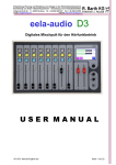
eela audio
D4
D4
Broadcast mixing desk
OPERATING MANUAL
EA Broadcast / Eela Audio, Het Riet 8 A, 5431NM Cuijk, The Netherlands
http://www.eela-audio.com e-mail: [email protected]
Thank you for the purchase of this D4 digital mixing desk. First read this manual carefully before
starting to use the apparatus. Please keep this manual so you can refer to it at a later stage.
Functions and / or layout of the touch screen of the D4 can vary due to different software versions.
More information is available on http://www.eela.nl/D4TI
GENERAL REMARKS:
The D4 is designed in a way that most of the functionality is self-explaining and easy to understand by
the experienced radio studio operator.
Due to the flexibility and multi purpose nature of the unit some settings need extra attention
especially the setup of hybrid connections and the integration in an automated environment.
Software version 1.xx
INDEX
Connections
4
System overview
5
Control surface
5
System settings
7
Monitors
8
System
10
Main screen and Login
12
Universal contacts
14
Meters
15
Channel settings
18
Cleanfeeds, N-1, foldback, outside source return, cough signal
21
Setup examples, Control room microphone, studio microphone, hybrid setup
23
GPIO pinout
26
General specifications
27
This product is in conformity with the requirements of the CE directives.
Eela Audio D4 manual
2
Eela Audio D4 table top digital mixing console:
Quick start manual
All digital "universal" broadcast mixing console with 32 + 4 inputs, 16 input faders and 2 touch screen
color displays and a total of 16 outputs. This is sufficient for most modern radio applications:
APPLICATIONS:
The Eela Audio D4 is designed for use in modern radio and television broadcast applications for On-Air
and or production studios.
Digital mixing console, rugged mechanical construction
32 (+4) inputs, 3 main outputs, 10 configurable stereo outputs
16 input faders with ‘Channel On, Start’ buttons
Color touch screen for settings, E.Q., dynamics, configuration
Separate color touch screen for meters
OLED display with status information and input meters
Broadcast audio and logical functions
Extra internal TDM bus for future or 3th party expansion
Eela Audio D4 manual
3
CONNECTOR PANEL:
All connections to and from the mixing desk are concentrated on the back. The main analogue and
digital audio connections are balanced on XLR-type connectors. The connections for monitoring and
AUX 6 – 10 are stereo, unbalanced on 6,3 mm jack.
Connections:
All connections to and from the mixing desk are “industry standard”:
Inputs:
Microphone, AES/EBU balanced
Line inputs, balanced L and R
XLR female
XLR female
Pin 1 gnd; pin2 +; pin3 –
Pin 1 gnd; pin2 +; pin3 –
Outputs:
Main analog outputs L and R balanced
Main digital AES/EBU outputs balanced
XLR male
XLR male
Pin 1 gnd; pin2 +; pin3 –
Pin 1 gnd; pin2 +; pin3 –
Aux 6..10 unbalanced
Monitor loudspeaker unbalanced
Headphones
6,3 mm jack
6,3 mm jack
Tip left; ring right; sleeve gnd
6,3 mm jack
Tip left; ring right; sleeve gnd
Tip left; ring right; sleeve gnd
TB1 and TB2
6,3 mm jack line inputs to connect an amplified TalkBack microphone or
interfacing with 3rd party intercom systems.
LAN RJ45 connector for future use
D25 multipin connectors for general purpose input and output switches
DBUS RJ45 connector for expansion units like:
The EA963, a 19” 1U A rack unit with and additional 2 x 8 GPI/O contacts as well as 4 solid state AC
relays for switching lamps.
USB standard connector to connect to a computer for firmware updates and control by automation
software like CAPS2.
8 balanced microphone inputs with individually switched 48 Volt phantom powering.
8 AES/EBU balanced digital inputs with sample rate converters range: 22kHz.> 200 kHz
16 balanced analogue inputs.
8 balanced analogue outputs, 2 main outputs, 1 record output, 5 aux.
8 AES/EBU outputs 48 kHz sample rate
5 unbalanced aux outputs
Loudspeaker headphones output unbalanced
External monitor inputs, Talkback inputs unbalanced on 6,3 mm jack
MIO connector, future or 3th party expansion for multichannel USB audio or network audio
Eela Audio D4 manual
4
SYSTEM OVERVIEW
CONTROL SURFACE
16 Channel input faders each with 4 pushbuttons with LED and OLED display:
Selecting the top grey button opens the channel window in the touch screen
display. The red LED in the left top corner of the button will lit indicating the
channel control and information is displayed in the main screen.
The TB button is only active for TalkBack if an output aux is coupled to this
channel. Pressing this button short the function toggles on or off, holding down
the knob (> 1 sec) it will switch off as soon as you release it. See further on in
this manual to setup a system.
The yellow button is PFL, pre fade listening, the LED indicates an active state.
PFL can be mixed or individual.
White button is the ‘START’ button and LED. This function can be activated in
the ‘settings’ menu of each channel. If active the LED will blink if pressed
indicating a ready status, faderstart command will be fired upon opening of a
fader. Or the other way round, the LED will blink fast upon opening of the fader
and the faderstart command will become active after pressing the ‘start’ button.
A steady LED indicates the active state of the faderstart. If ‘BTN start’ in the
settings menu is not selected the start command is the normal faderstart and
the LED is steady lit upon opening of the fader.
This LED will blink slowly if an external MUTE signal is applied.
The functions of the OLED displays above each fader:
On the left of the OLED is a meter bar that gives you an indication of the input
level,
Symbols indicate the status of the channel,
- The exclamation mark is visible in the case of an input overload.
- The “ON” indicates the on status of the channel.
- “TEL” indicates that the channel is programmed as a telco input /
output.
- “REC”, “A” and “B” are the outputs the signal is routed to.
Of course the name of the channel is displayed and the bottom line displays
additional status information.
Eela Audio D4 manual
5
Meterbridge controls:
Pfl speaker and volume control on the left hand side
Meter display on the right.
Main control screen in the middle:
3 Rotary / selectors for use in conjunction with the touch screen. The function of these rotaries will
dynamically change. The momentary function is displayed in a colored box on the right hand side of
the screen. The color and icon in this box changes with the function.
Touching a volume bar or settings box the background changes color and you can adjust with the
help of the appropriate rotary. Volume bars turn white and a change is momentary executed. The
backgrounds of the setting boxes turn yellow and you can change the setting with the rotary. You
have to confirm the change by pushing on top of the rotary.
MAIN SCREEN:
In the main screen you can operate the built-in timer. On the right hand side are the icons for control
room monitor loudspeakers and headphones, here indicating that the rotary next to it operates as
volume control for the speakers and phones. Below this icon you see the name of the selected source.
The “TEL” icon will tell you one or more hybrids are off-hook by showing a lifted headset.
The main screen has 2 extra buttons “On-Air” or “TA” each coupled to a GPO and a GPI. These can be
used for signaling and as standard switches or operated in a ‘handshake’ mode.
Eela Audio D4 manual
6
SYSTEM
The ‘system’ button in the main screen will open the system settings menu:
To change touch the number in the box, this will turn into yellow background, next to the bottom
rotary a yellow field appears. Turn the rotary to change the input and confirm this by pushing the
rotary switch. Note that the other two rotaries will stay active for monitor and headphones volume
control.
‘TB rec from’
Select the microphone input which is used for talkback, in many cases the DJ
microphone above the mixing desk. Or you can also choose the TB1 or TB2
inputs on the back.
‘Studio Monitor’
If applicable AUX10 can be used as a studio monitor / foldback. In that case an
icon will appear in the monitor section to select a source and the associated logic
is applied. If your setup is used without a separate studio you can use AUX10 as
a standard aux.
‘Studio LSP dim’
The studio foldback loudspeaker can be set to dim upon opening a fader that is
configured as a studio microphone. The amount of decrease in volume can be
set here.
‘CR LSP dim’
The control room monitor loudspeaker can be set to dim upon opening a fader
that is configured as a control room microphone. The amount of decrease in
volume can be set here.
‘PFL dim’
The pre fade listening loudspeaker can be set to dim upon opening a fader that is
configured as a CR microphone. The amount of decrease in volume can be
set here.
‘GPI loads PRESET’ External contacts, GPI inputs, can be used to load a preset, e.g. controlled by an
automation system.
‘GPO is...”
Control room sign or Studio sign, selects the output contact that controls the
control room or studio “ON-AIR” lamp. This can be one of the 24 internal
contacts or a solid state relays in the EA963 expansion box.
“ON-AIR, TA’
GPIO contacts assigned to the universal buttons “On-Air” and “TA”
If you do not assign a GPO – GPO set to ‘0’ - an incoming signal (GPI) will turn
the color of the button into red.
Eela Audio D4 manual
7
MONITOR
Both Control room loudspeaker, headphone and studio icons hide a source
selector. You can select the source for the monitor speakers and the
headphones by touching the icons and the source selector will open. A selected
source is immediately executed.
The name of the source is displayed underneath the icon.
Source selector for speaker / headphones
In addition you can touch the check-boxes in the monitor select screen for the other functions:
‘PFL to LSP’
routes the PFL signal to the main monitor speakers if a PFL button of one of the
modules is active and replaces the selected monitor signal.
‘PFL to headphones’ routes the PFL signal to the headphones if a PFL button of one of the
modules is active and replaces the selected headphones signal..
‘Mixed PFL’
Standard pfl switches are mutually releasing. Check this box to mix the pfl
signals.
Note: if mixed PFL is used Talkback becomes active for all channels in PFL mode that have an AUX
coupled to them! See ‘TB output channel’ in CHANNEL SETTINGS
STUDIO MONITOR
The ‘STUDIO’ icon is only visible if AUX10 is assigned as studio monitor; see
‘System settings / ‘Output select’
You can select the source for the studio monitor speakers by touching the icon
and the source selector will open.
The name of the source is displayed underneath the icon.
Note: You can program any aux to follow the dim and TalkBack function of a studio foldback but
without the choice of selecting different outputs, see paragraph below.
Eela Audio D4 manual
8
SYSTEM
Master auxiliary settings menu sets the AUX for ‘Pre’ or ‘Post’ fader.
If a Studio monitor check box is active the Studio monitor DIM function is
applied to this AUX upon opening a “Studio Microphone” fader.
‘GPI’ and GPO’
Here you can also set the type and shape of the GPIO’s: pulse (edge) or
continuously, inverted or not….
You can step trough the pages for the settings of the GPI and GPO 1 to 24 on
the D25 connectors on the back and for 25 onwards on an EA963 extender unit.
The same applies to the General Purpose Outputs.
NOTE THAT AN INVERTED GPI WILL BE ACTIVE WHEN NO CONNECTION IS MADE!! E.g. if you have
assigned a GPI to an input mute that channel will be muted if the switch is not connected!
If set to “EDGE” the GPI signal will toggle the function ’on’ on the first pulse and ‘off’ on the second.
Software power off, the D4 will stay in stand-by mode.
The unit has a hardware power switch in the back. It is recommended to use this
switch to shut off the unit. If the unit is mounted in a table were you cannot
reach this switch you can shut down (sleep mode) the unit in software.
By holding down the ‘settings’ rotary for 3 seconds the unit will power up again.
Please note: From this state the unit will also switch on if the (mains) power was
down and switched on again!
Eela Audio D4 manual
9
MAIN SCREEN
‘outputs’
This is the master volume settings screen for all the available outputs.
Selecting the OUTPUT LEVELS button in the main screen opens an overview of
all output levels. This is an important tool to keep track of all the signals going
out.
Just select a bar, this will turn red, adjust the volume with the rotary and push it
to confirm. The volume is adjusted in real time. The ‘AES/EBU button
gives access to the digital output options:
‘digital outputs’
By default the digital AES/EBU outputs are linked to the main outputs and the
first 5 universal ‘Aux’ outputs. This configuration can be changed e.g. to have a
digital output for monitoring or a digital output carrying the same signal as the
headphones.
To adapt the digital audio level to the various standards used you can also
change the digital audio level vs analogue and meter levels over a 20 dB range.
Eela Audio D4 manual
10
‘preset’
You can store / recall up to 16 presets.
ALL SETTINGS ARE SAVED INCLUDING ALL PARAMETERS FOR EACH INPUT SEPARATLY!
Please note:
Changes made in the settings will be lost at power off unless saved in a preset!
With check boxes you can indicate how the unit will behave at power-up. You can choose one of the
presets to load at start-up or the last loaded preset. In the SYSTEM / GPIO menu you can assign a
GPI to load up to 2 presets with external contact closures. Be aware that also this setting is stored in
a preset! Loading a different preset by means of a contact closure without a contact assigned will
switch this off!
All settings are stored in memory with a battery back-up. This battery will last at least 5 years under
normal conditions. The battery is a widely available type CR2032 or equivalent that is commonly used
in PC’s for the same purpose. A qualified technician can change this (internal) battery.
In the event of a firmware upgrade all settings will be lost. It is recommended to write down your
basic settings and keep these in a safe place.
MAIN SCREEN
‘LOGIN’
The eela audio logo hides a login screen
A login code gives access to the system settings and / or channel configuration
as well as enables the user to store presets. Once logged in you can log-off in the
same way. The factory default password is “0000” . You can simply change this
in the “change passw” screen. The password can be up to 15 characters long.
Eela Audio D4 manual
11
Without logging in you can use the mixing console for normal operation:
You can recall presets,
Select inputs to faders,
Make channels the operational adjustments e.q., compressor limiter, gain and aux levels,
Change the output levels,
Use the monitor facilities and operate the timer.
‘timer’
The main display is used as a Program timer
On the bottom left you will find an indication which fader is used as the event
triggering.
Tapping this clock in the main window gives you access to the setting.
Just enter an INTRO and / or TOTAL TRACK time. The TRIGGER is the fader
number that starts the countdown.
You can select any of the 16 faders by tapping the TRIGGER box, this will turn
yellow and enter a number by turning the rotary or simply hitting the ‘select’
Eela Audio D4 manual
12
UNIVERSAL CONTACTS
These button control GPIO contacts that can be used to switch an on-air matrix and the signal for
traffic announcement but due to the universal character of the system these can be used for any
other purpose a switch is needed and / or a signal has to be displayed.
The main screen has 2 extra buttons coupled to a GPO and a GPI. These can be used for signaling
and as standard switches or operated in a ‘handshake’ mode.
Pressing one of the buttons “On-Air” or “TA” the assigned GPO will switch and
the background color changes into green as a sign that the GPO is on.:
Pressing the button again from this state the GPO switches off and the color
turns into default (blue) again.
At an acknowledgement on the assigned GPI the color changes into red:
To prevent unintentional switching you can now only switch this off by touching
and holding the button (> 2 sec).
In case the external GPI is activated from the default state the color of the
background changes into yellow:
By subsequently pushing the button it will turn red and the GPO closes.
As an example by wiring this GPO in series with a fader contact of a microphone this can be used to
control a traffic announcement system.
Eela Audio D4 manual
13
METERS
Tapping on one of the meter bars will open a meter select screen in the main
display. It allows for selecting the meter source. The current selection is
displayed in the label on the left hand side of each meter pair.
Currently only active PPM characteristics.
The standard alignment of the mixer outputs:
0 PPM is + 6 dBu at the balanced analog outputs
+10 PPM is 0 dBFS
See the section “Outputs” for changing the digital audio levels vs analogue outputs!
Eela Audio D4 manual
14
CHANNEL SETTINGS:
Input select:
Each input fader has a “select”, “TalkBack”, “pfl” and “start” button above the fader. Briefly pushing
the grey “select” button opens the main ‘settings for input’ window in the display:
Touching one of the bars (gain, balance/pan or e.q. etc.) changes the color of
The bars in the block, the function of the rotary’s change and you can make the
necessary adaptions. You can see the momentary function in the labels next to
the rotary. Changes are executed in real time.
Gain and balance are operated in the same way. An aux level can be changed in
2 ways: You can select one of the 10 aux-es here and adjust the level or you can
open the ‘aux mix’ window to get an overview. (see below)
The small meter on the channel OLED display can be used to set the GAIN of an
input. E.Q. and dynamics can be switched on / off in the check-boxes. In the
same way you can adjust the compressor ratio.
‘REC’ and ‘ISOLATE’ Choose the box ‘REC” if you want your signal to route to the recording (REC)
output. In order to keep the signal off-air also tap the ’ ISOLATE’ box. In this way
you can make a recording independent from the on-air signal.
‘Aux mix’
NOTE: You can “scroll” through all the input channels by tapping another one of the grey “SELECT”
button above the faders while staying in the same settings level. This allows adjusting the same aux
for all channels in a fast and easy way.
Eela Audio D4 manual
15
CHANNEL SETTINGS
The brown telephone icon is only present when the channel is set up as a Telco
channel (hybrid).
With this button you can open the “Telco” window to switch the external hybrid
on/off hook and dial a number. The unit has a built-in DTMF generator. (No
internal hybrid!) A normal hybrid is transparent for these DTMF tones.
‘config’
Pressing the ‘config’ button opens the configuration menu for this channel.
Please note: Some settings can only change when fader is closed!
‘Input type’
you will set the logic behavior of the channel:
‘CR microphone’, Monitor speaker will MUTE or DIM upon opening of this channel
fader as well as activate the CR red-light.
‘Studio microphone’, Studio monitor will DIM upon opening of this channel fader
as well as activate the STUDIO red-light.
The amount of DIM can be set in the SYSTEM setting.
Eela Audio D4 manual
16
CHANNEL SETTINGS
‘Hybrid’ In case you connect a telephone hybrid to this input.
‘Config’ Can be ‘stereo’, ‘swapped L+R’, Left to mono, Right to mono, mono to
both. Although displayed this is not active in MIC mode as a microphone is
always mono so settings here will have no effect.
‘Line’ a line input without any special influence on the logic of the desk.
This setting is independent from the selected input type. You can program a line or digital input to
“behave” as a microphone input. This allows you to use an external microphone preamplifier
connected to a line input and still keep the system logic of a microphone channel.
‘TB output channel’, if needed an aux output can be coupled to this input for Talkback purposes.
E.g. a feed to a presenter headphone or TalkBack to a hybrid or other “Outside
Source”. If set this will activate the green “TB” button on the fader channel.
‘TBP output channel’, second Talkback output, TalkBackProducer has the same function as above, but
from another source.
‘Inv L and Inv R’
Check boxes for the phase reverse function. To reverse the phase of a
microphone select both.
Careful: Left or Right phase reversed and input ‘Config’ in mono will cancel the signal!
When used in the right way this can be used for decoding M+S stereo, see
separate documentation.
‘Phantom’
Only in MIC Mode: 48 V PHANTOM power switch. The 48V phantom powering is
individually switched for each microphone input.
‘BTN start’
Button start, .if active the LED on the “start” button of the channel will blink fast
if pressed indicating a ready status, faderstart command will be fired upon
opening of a fader. Or the other way round, the LED will blink fast upon opening
the fader and the faderstart command will become active after pressing the ‘start’
button. A steady LED indicates the active state of the faderstart. If ‘BTN start’ in
this settings menu is not selected the start command is the normal faderstart and
the LED will steady lit upon opening of the fader.
(This LED will blink slowly if an external MUTE signal is applied.)
‘Main A’, ‘Main B’
Check boxes to route the channel signal to one or both main outputs.
This is also visible in the channel’s OLED display.
Eela Audio D4 manual
17
CHANNEL SETTINGS
‘GPI’ and ‘GPO’
General Purpose Inputs and Outputs are opto isolated contact closures. On the
mixing desks itself are 24 input contacts and 24 output contacts available on 3
D25 connectors. With the EA963 expansion unit you can add 16 inputs and 16
outputs extra as well as 4 solid state relays to drive mains voltage warning
lamps.
The type and shape of the I/O’s can be set in the main systems menu.
General Purpose Inputs are:
External mute, remote Pfl on, Fader bypass, and if the channel is activated as
‘hybrid’ also “ringtone detect”.
‘Fader bypass’ switched the channel on to unity gain and the ‘faderstart on’
independent of fader setting.
General Purpose Outputs can be:
Faderstart, Pfl. Out and if activated as ‘hybrid’ also modem (hybrid) on.
Example: If an External mute and remote Pfl on are set to the same GPI number an external contact
closure of this GPI will mute the channel and at the same time switch the Pfl on. This is often known
as “cough” function allowing a presenter to contact the technician off-air.
CHANNEL SETTINGS
The “SELECT” button open the input matrix:
To select an input to the fader channel simply select one and press the “OK”
button. With the left and right arrow you can step trough the pages. The D4
without MIO active has 2 pages for in total 32 inputs.
Eela Audio D4 manual
18
CHANNEL SETTINGS
The “EDIT” button opens a text window to change the name of the selected
input. This name you will also see in the OLED channel display.
Text editor
The text editor is used to change channel names. The length of a channel
name can be up to 10 characters.
Eela Audio D4 manual
19
Cleanfeeds, N-1, foldback, outside source return, cough signal:
There is a lot of confusion mainly about the names of the same kind of signals so let’s take a closer
look:
CLEANFEED or N-1 or OUTSIDE SOURCE:
Basically this is the (mono) signal that goes back to a caller into a telephone hybrid. The signal
consists of a mix of all signals in a program MINUS the signal that comes FROM the hybrid INTO the
channel of the mixing desk. This signal from the hybrid back into the mix will cause a feedback and
that is something we do not want. In radio broadcast mixing desks this signal can be a separate POST
FADE AUX bus without the incoming signal from the hybrid.
In some analog mixing desks this is not a separate bus but the signal is made from the total sum and
mixing this with a phase reversed version of the unwanted signal. This is OK as long as it is limited in
frequency range so it is mainly used for telephone hybrids.
Also upon switching on the TalkBack the signal is replaced by the microphone signal in order to talk to
the caller off air without the public hearing this conversation. If the damping of the hybrid allows this
can also be done on-air.
In the D4 a dedicated STEREO full bandwidth AUX bus is used for this purpose. Other than only
hybrids also full bandwidth stereo communication devices can be used (ISDN Codec).
With this system you can also couple 2 or more D4 mixing desks in separate rooms together without
the danger of feedback.
A special mode is putting the AUX-es in “pre-fader mode”, this allows incoming callers to talk to each
other off-air: CONFERENCE mode. This can be useful when 2 or more reporters are active that need
to know about each others activities. However they should be aware when they are on and off-air!
HEADPHONES FOLDBACK:
The signal that is fed to the headphones of a presenter. Basically the total mix of the main signal.
In order to allow the technician behind the mixing desk to talk to the presenter this signal is replaced
by the microphone signal if the TalkBack button is pushed.
With the D4 an AUX bus is used for this purpose and you can even built a dedicated mix e.g. lower
volume of the music contributions. It is not a cleanfeed signal as the presenter headphones needs the
own signal back to hear his/her own voice!
COUGH:
The cough signal is engaged with a pushbutton in the studio. Pushing this button switches the
microphone off the main mix and switches on the pfl. In this way the presenter can talk to the
technician off- air. In the D4 you can connect an external switch to one GPI and select both “mute”
and “remote pfl” of the microphone channel to the same GPI. If an external “mute” is applied the
START button LED will blink slowly.
Eela Audio D4 manual
20
STUDIO MONITOR FOLDBACK:
The AUX output configuration screen in the main menu.
The signal that is fed to the loudspeakers in the studio room. This signal can be adapted depending
on your way of working. In some radio studio’s (or TV) people don’t use headphones. With an AUX
you can make a mix of all post fade signals EXCEPT the studio microphones. The signal can be loud if
no microphones are in use and dimmed upon opening of one of the studio microphones. The amount
of dimming can be adjusted in the D4. Also this signal is replaced by a TalkBack signal upon pushing
the TB button.
As the D4 mixing desk can be used in a true “split” mode e.g. an automated program is playing on air
and at the same time making a recording you have to be able to select which signals must be present
in the CLEANFEED, FOLDBACK or RETURN. That is why an post fade AUX is used for this purpose and
you have to open up the AUX volume controls of ALL channels that must be present in this mix en
close the others.
Eela Audio D4 manual
21
Setup examples:
Setting up a CONTROL ROOM MICROPHONE:
Connect the control room microphone to one of the MIC inputs.
Briefly pushing the grey “select” button that opens the channel settings window in the display.
Push the blue “config” button on the touch screen that will open the settings window:
Select the input microphone, and briefly touch the “Input type” box, the background will turn yellow,
with the rotary select “CR micr” and push the rotary button to confirm the selection.
If you are using a condenser microphone select the box “PHANTOM”.
Briefly push the “TB-output chan” box and with the rotary select “off” as in most cases you do not
need a TB channel assigned to a CR microphone. Confirm the selection by pushing the rotary.
Select the “MAIN A” and or the “MAIN B” box depending on the destination of the signal.
NB. The “Config” button mono/stereo has no effect in MIC mode.
Briefly touch the grey “select” button again to return to the main screen and select “system”.
Select the box “CR LSP dim” and with the help of the rotary select amount the monitor speakers will
dim upon opening the CR microphone fader in order to prevent feedback.
In case you will need to setup a TalkBack system to other sources you can use your CR microphone
as a TB microphone:
Select the box “TB input ch” and with the help of the rotary select the channel on which the CR
microphone is connected. This will than be your TB microphone.
Eela Audio D4 manual
22
Setting up a STUDIO MICROPHONE with TB facility:
Connect the studio microphone to one of the MIC inputs.
Briefly pushing the grey “select” button that opens the channel settings window in the display.
Push the blue “config” button on the touch screen that will open the settings window:
Select the input being microphone, and briefly touch the “Type” box, this will turn yellow and with the
rotary select “Studio micr” and push the rotary button to confirm the selection.
If you are using a condenser microphone select the box “PHANTOM”.
Select the “MAIN A” and or the “MAIN B” box depending on the destination of the signal.
You can assign one of the “AUX” outputs of the mixing desk as a return feed for the headphones of a
presenter. Briefly touch the “TB-output” box and with the rotary select the “AUX” that you link to this
channel as a feedback to the headphones of the presenter. Confirm the selection by pushing the
rotary. As an example select “AUX6”.
Of all inputs you want the presenter to hear adjust the volume of “AUX6” to the desired level and
don’t forget the master volume of AUX6 in the Levels screen.
Please note all AUX levels depend on and are stored with the selected INPUT so if you switch inputs
on a channel you have adjust that level also!
If an External mute and remote Pfl on are set to the same GPI number an external contact closure of
this GPI will mute the channel and at the same time switch the Pfl on. This “cough” function allowing
a presenter to contact the technician off-air. In the example above both ‘mute’ and ‘remote PFL’ are
set to GPI 2.
Briefly pushing the grey “select” button above the fader again to return to the main screen.
* the given aux numbers are just an example, you can choose any free aux.
Eela Audio D4 manual
23
Setting up a HYBRID INTERFACE:
Connect the hybrid to one of the line inputs in this case we will use input channel 15 left. In most
cases a telephone hybrid is mono so connect its output to the left input and set the ‘config:’ to mono L
For this example we are using AUX6 as return to the hybrid so connect the AUX6 output to the input
of the hybrid with both L and R connected.
In this example we will be using GPI 14 for “ring detect” and GPO 15 for “hybrid ON” .
Connect the hybrid accordingly.
Briefly pushing the grey channel 15 “select” button that opens the channel settings window in the
display.
Push the blue “config” button on the touch screen that will open the settings window:
Select the input being LINE A, and briefly touch the “Type” box, the background will turn yellow, with
the rotary select “hybrid” and push the rotary button to confirm the selection.
Briefly push the “TB-output” box and with the rotary select “AUX6” being your return or Cleanfeed.
Confirm the selection by pushing the rotary. This also activates the green TB button above the fader.
Select the “MAIN A” and or the “MAIN B” box depending on the destination of the signal.
EXIT this screen and go to the channel AUX settings and make sure the level of AUX 6 is completely
turned down to mute. (one level up)
Of all inputs in all other channels that are part of or will be part of the return signal open AUX6 to the
desired level, in most cases nominal level.
Please note all AUX levels depend on and are stored with the selected INPUT so if you switch inputs
on a channel you have to adjust that level also!
Repeat the settings for the TBP output channel if appropriate.
Setup your Talkback microphone in the SYSTEMS menu ‘TB input ch:’ as described earlier.
GPIO
Standard for an Eela Audio hybrid the shape and type of the GPIO’s are continuous so do not select
any checkboxes in the main GPIO settings menu
An incoming call is indicated by a flashing LED in the grey 'SELECT' button. An off-hook or ON state is
indicated by a slowly flashing LED. The telephone icon in the main screen indicates an of-hook state
of one of the hybrids connected.
Eela Audio D4 manual
24
In “Input select” mode of this channel a brown box with a telephone is visible. Touching this icon will
open the telephone screen to put the hybrid on and off hook and to dial a telephone number. Dialing
is done with and internal DTM tone generator and most hybrids are transparent for these tones.
You can connect several hybrids this way each using another AUX for the return signal. Make sure the
AUX volume of the corresponding input is closed and all others open.
D4 / EA815/1 telephone hybrid cable diagram:
In this example EA815/1 hybrid remote is connected to GPIO 1
Eela Audio D4 manual
25
GPIO schematic overview:
Pin no.
Description
GPI_1
1
14
GPO_1
GPI_2
2
15
GPO_2
GPI_3
3
16
GPO_3
GPI_4
4
17
GPO_4
GPI_5
5
18
GPO_5
GPI_6
6
19
GPO_6
GPI_7
7
20
GPO_7
GPI_8
8
21
GPO_8
NC
9
22
NC
10
23
+5V
NC
11
24
GND
NC
12
25
13
+5V
GND
NC
25 pin D-type connector pin layout for each of the 3 D25 connectors.
Eela Audio D4 manual
26
General:
Power Supply:
Wide range mains input, 100 .. 240 V AC, 47/63 Hz,
Operating environment temperature 0o to + 40o C.
Optional units:
GB34
GPIO breakout PCB with 1 meter data cable for 8 GPI’s and 8 GPO’s
EA924
19" 1U Quad input balancing unit,
4 x 2 high quality balanced input amplifiers, unbalanced out.
EA815
Electronic telephone hybrid, single or dual 19” version available.
EA816
GSM stationary telephone hybrid.
EA915
DSP digital POTS telephone hybrid.
Eela Audio D4 manual
27