1
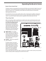
Resolv A Series Layout
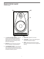
Rear Panel Layout - A8a
6
8
1. H
IGH FREQUENCY LEVEL – Four-position
switch used to adjust the high frequency
response (in 3dB increments).
5. Voltage SWITCH – Used to select the
operating voltage.
NOTE: Be sure to check the voltage setting is
correct for your country. Also, be sure to use the
correct fuse type when changing the voltage.
2. VOLUME - Controls the amount of output level.
3. X
LR INPUT (A6 and A8 only) - Balanced,
+4dBu line level input is connected here via
standard XLR (microphone) cable.
6. A
C INLET - Connect the supplied IEC power
cable here.
7. R
CA – Used to connect signals from unbalanced,
–10dBV devices.
4. POWER SWITCH – Main power switch.
8. 1/4-INCH
PHONE – Balance TRS (Tip, Ring, Sleeve) 1/4-inch phone plug used to connect
balanced or unbalanced +4dBu line level signals.