1
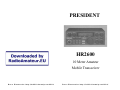
PRESIDENT
HR2600
10 Meter Amateur
Mobile Transceiver
Doc’s Electronics http://hr2510.homeip.net:2510/
Doc’s Electronics http://hr2510.homeip.net:2510/
Contents
Welcome! . . . . . . . . . . . . . . . . . . . . . . . . . . . . . . . . . . . . . . . . .2
Unpacking . . . . . . . . . . . . . . . . . . . . . . . . . . . . . . . . . . . . . .2
Controls and Functions . . . . . . . . . . . . . . . . . . . . . . . . . . . 3-5
Front Panel Connector . . . . . . . . . . . . . . . . . . . . . . . . . . . . . 6
CTCSS Control . . . . . . . . . . . . . . . . . . . . . . . . . . . . . . . . . . . 7
Setting & Using CTCSS . . . . . . . . . . . . . . . . . . . . . . . . . . .7
Switch Settings for S301 . . . . . . . . . . . . . . . . . . . . . . . . . . .8
Rear Panel Connectors . . . . . . . . . . . . . . . . . . . . . . . . . . . . . 9
Power Connector . . . . . . . . . . . . . . . . . . . . . . . . . . . . . . . 9
Antenna Connector . . . . . . . . . . . . . . . . . . . . . . . . . . . . . 10
Installation . . . . . . . . . . . . . . . . . . . . . . . . . . . . . . . . . . . . . 11
Transceiver Mounting . . . . . . . . . . . . . . . . . . . . . . . . . . . 11
Mobile Antenna . . . . . . . . . . . . . . . . . . . . . . . . . . . . . . . . 11
Ground Information . . . . . . . . . . . . . . . . . . . . . . . . . . . . 11
Power Cord Connection . . . . . . . . . . . . . . . . . . . . . . . . . 11
Operation . . . . . . . . . . . . . . . . . . . . . . . . . . . . . . . . . . . . . . 12
Selecting a Frequency . . . . . . . . . . . . . . . . . . . . . . . . . . .12
VFO Operation . . . . . . . . . . . . . . . . . . . . . . . . . . . . . . . . 12
Repeater Operation . . . . . . . . . . . . . . . . . . . . . . . . . . . . . 12
USB/LSB/AM/FM Operation . . . . . . . . . . . . . . . . . . . . . 12
Noise Blanker . . . . . . . . . . . . . . . . . . . . . . . . . . . . . . . . . 12
F. Lock . . . . . . . . . . . . . . . . . . . . . . . . . . . . . . . . . . . . . . 12
CW Operation . . . . . . . . . . . . . . . . . . . . . . . . . . . . . . . . . 13
Receive Scanning . . . . . . . . . . . . . . . . . . . . . . . . . . . . . . 13
Scanning Operation . . . . . . . . . . . . . . . . . . . . . . . . . . . . . 13
Multifunction Meter . . . . . . . . . . . . . . . . . . . . . . . . . . . . 14
S/RF Meter . . . . . . . . . . . . . . . . . . . . . . . . . . . . . . . . . . . 14
MOD Meter . . . . . . . . . . . . . . . . . . . . . . . . . . . . . . . . . . 14
SWR CAL Meter . . . . . . . . . . . . . . . . . . . . . . . . . . . . . . 14
SWR Meter . . . . . . . . . . . . . . . . . . . . . . . . . . . . . . . . . . . 15
Specifications . . . . . . . . . . . . . . . . . . . . . . . . . . . . . . . . . . . 16
General . . . . . . . . . . . . . . . . . . . . . . . . . . . . . . . . . . . . . . 16
Transmitter . . . . . . . . . . . . . . . . . . . . . . . . . . . . . . . . . . . 16
Receiver . . . . . . . . . . . . . . . . . . . . . . . . . . . . . . . . . . . . . 16
Troubleshooting . . . . . . . . . . . . . . . . . . . . . . . . . . . . . . . . . 17
Amateur Radio Operation . . . . . . . . . . . . . . . . . . . . . . 18-19
One Year Limited Warranty
WARRANTOR: UNIDEN CORPORATION OF AMERICA (“UNIDEN”.)
ELEMENTS OF WARRANTY: UNIDEN warrants, for the duration of this
warranty, UNIDEN CB Product (hereinafter referred to as the Product) to be free
from defects in materials and craftsmanship with only the limitations or exclusions
set out below.
WARRANTY DURATION: This warranty shall terminate and be of no further
effect one (1) year after the date of the original purchase of the Product or at the
time the Product is (A) damaged or not maintained as reasonable or necessary, (B)
modified, (C) improperly installed, (D) repaired by someone other than warrantor
for a defect or malfunction covered by this warranty, (E) used in a manner or
purpose for which the Product was not intended, or (F) sold by the original
purchaser.
STATEMENT OF REMEDY: In the event that the product does not conform to
this warranty at any time while this warranty is in effect, warrantor will repair the
defect and return it to you without charge for parts, service, or any other cost
incurred by warrantor or its representatives in connection with the performance of
this warranty. THIS WARRANTY DOES NOT COVER OR PROVIDE FOR THE
REIMBURSEMENT OF PAYMENT OF INCIDENTAL OR CONSEQUENTIAL
DAMAGES. Some states do not allow this exclusion or limitation of incidental or
consequential damages so the above limitation or exclusion may not apply to you.
WARRANTY REGISTRATION CARD: In order to facilitate the servicing of
this warranty by warrantor, the Warranty Registration Card should be returned to
the warrantor. However, return of the Warranty Registration Card is not a precondition of this warranty, and this warranty will be observed by the warrantor whether
or not the Warranty Registration Card is returned, provided that other satisfactory
evidence of the date of purchase is provided.
PROCEDURE FOR OBTAINING PERFORMANCE OF WARRANTY: In the
event that the Product does not conform to this warranty, the Product should be
shipped or delivered, freight prepaid, with evidence of original purchase, to
warrantor at:
UNIDEN CUSTOMER SERVICE CENTER
9900 Westpoint Drive
Indianapolis, IN 46250
LEGAL REMEDIES: This warranty gives you specific legal rights, and you
may also have other rights which vary from state to state. This warranty is void
outside of the United States of America.
Warranty . . . . . . . . . . . . . . . . . . . . . . . . . . . . . . . . . . . . . . 20
Doc’s Electronics http://hr2510.homeip.net:2510/
Doc’s Electronics http://hr2510.homeip.net:2510/
Welcome!
NOTES/MEMOS
To the world of 10 Meter amateur radio communications! You have purchased what
we feel to be the finest 10 Meter mobile transceiver available. Your HR 2600 has
been designed using the latest state of the art electronics to give you years of trouble
free service. To get the most from your HR 2600, please read this operating guide
thoroughly.
WARNING: To operate this transceiver, you MUST have an
FCC Radio Amateur Operator’s license. Operation of this
device without a license is ILLEGAL and carries heavy
penalties.
Unpacking
Your HR 2600 is supplied with the following items. If any items are missing or
appear damaged, DO NOT return the unit to the place of purchase. Instead, contact
Uniden Customer Service at (317) 842-2483, 8 am-5 pm EST, Monday through
Friday.
HR 2600 10 Meter Transceiver
Dynamic Microphone with Channel Up/Down control
Transceiver & Microphone Mounting Brackets & Hardware
Power Cord with In-Line fuse holder Accessory Plug
(Jumpered for internal speaker use)
Accessory Plug (With wires for connecting accessories)
This operating guide
We also recommend that you retain the original box and packing, as it makes a
convenient way to transport the unit.
Doc’s Electronics http://hr2510.homeip.net:2510/
Doc’s Electronics http://hr2510.homeip.net:2510/
Controls and Functions
1. Mode Switch - This control is used to select the desired transmit mode. The
modes available are: CW, LSB, USB, AM, and FM.
2. SWR/CAL Control - This control is used to adjust the calibration of the SWR
meter while in SWR CAL mode.
3. RIT Control - The Receiver Incremental Tuning control is used to fine tune the
received signal. This is used in USB and LSB modes to obtain maximum clarity of
reception, and in CW mode to control the pitch of the beat note. The RIT control
can tune the receive frequency about ± 3 kHz. This control will not affect the
transmit frequency, or the frequency display, but will change the receive frequency
4. RIT Switch - This switch enables or disables the RIT control. Press to enable
(button down). Press again to disable (button up).
5. RF Gain Control - This is used to vary the RF input to the receiver. This control
is used to help eliminate strong, adjacent signals
6. Mic Gain Switch - Pressing this switch activates the built-in microphone
attenuator. This feature is designed to be used when operating the HR 2600 in high
ambient noise environments
7. TX Switch - The TX switch is used to lock the transmitter on for tuning
purposes, except in CW mode. In CW mode the external key must be locked down.
The microphone is disconnected unless the PTT switch is also depressed
8. Meter Switch - This switch is used to select the operating mode for the
multifunction meter. The meter modes are: S/RF, Modulation, SWR Calibration
setting, and SWR. Each time the Meter switch is pushed, the next mode is selected.
See the operation section for more information on meter usage. The currently
selected mode is displayed above the meter.
9. NB Switch - Pressing this switch enables the built in noise blanker. The noise
blanker in your HR 2600 is very effective in eliminating interference generated by,
vehicle ignition systems.
Doc’s Electronics http://hr2510.homeip.net:2510/
NOTES/MEMOS
Doc’s Electronics http://hr2510.homeip.net:2510/
Amateur Radio Operation - continued
Eventually, you’ll probably want to get another, higher class of amateur license,
with more privileges. Exams for Technician, General, Advanced, and Extra Class
licenses are given by three-member Volunteer Examiner Teams. Hundreds of exam
sessions are held across the country every month, most on weekends. (You can take
the Novice exam from a Volunteer Examiner Team, too, if it’s more convenient.)
When you’re ready, you can get a schedule of exam opportunities in your area from
the ARRL
We’ve mentioned the ARRL several times. That’s because the League is the
national organization that represents Amateur Radio in the United States. The
League has more than 150,000 members; most of them hams, but including lots
of hams-to-be. Here’s the address of ARRL Headquarters
The American Radio Relay League
225 Main Street
Newington CT 06111
The ARRL staff helped us prepare this section of the operating guide, and they would
be glad to hear from you if you need more information, or if you’d like to join!
Doc’s Electronics http://hr2510.homeip.net:2510/
Controls and Functions - continued
10. Dim Switch - Pressing the Dim switch dims the display backlighting. Press again
to return backlighting to its normal (high) level.
11. Scan Switch - The Scan control is used to scan up to 100 frequencies in each band
segment. See the section on operation for more information on using the Scan Control.
12. Span (Step Size) Switch - This control is used to select either 10 kHz, 1 KHz, or
100 Hz steps for the VFO. The currently selected step is indicated by a line under the
relevant digit on the Frequency Display.
13. A and V - Pressing these controls will step up or down in frequency by the amount
of the span control.
14. Band Switch - Pressing this control will select one of the four band segments.
Band segments are: a:28.0000 - 28.4999, b:28.5000-28.9999, c:29.0000-29.4999,
and d:29.5000-29.6999 MHz. The currently selected band segment is displayed next
to the frequency display.
15. F. Lock Switch -Pressing the Frequency Lock button will disable all frequency
determining controls on the front panel (except RIT) and on the microphone, to
prevent accidental changes of frequency.
16. Digital VFO Control - The Variable Frequency Oscillator control is used to select
the desired transmit and receive frequency. Tuning is continuous throughout the entire
range of the HR 2600, with no need to select band segments.
17. Squelch Control - The Squelch control is used to adjust the squelch function,
which eliminates the “rushing” sound between transmissions. Turning the squelch
control CCW until it clicks enables the auto squelch, eliminating the need to manually
adjust the squelch.
18. On/Off/Volume Control - This control is used to turn the unit on or off and to
adjust the volume.
19. RPT Switch - Pressing this control enables the 100 KHz frequency split for FM
repeater operation. When selected, a “P” is displayed above the band segment display.
Doc’s Electronics http://hr2510.homeip.net:2510/
Controls and Functions - continued
20. Multifunction Meter - This meter can display S/RF, Modulation, SWR Cal, or
SWR. See item (8), Meter Switch and the operation section for more information.
21. Frequency Display - The Frequency Display displays the currently selected
transmit and receive frequency.
22. Meter Mode Display - Displays the currently selected meter operating mode.
23. Band Segment Display - Shows the currently selected band segment.
24. Repeat Mode Display Shows a “P” if repeater mode is selected.
25. TX Indicator - Illuminates when PTT or TX Switch is pressed, or CW key is
down.
26. VFO Step Indicator - Displays the currently selected VFO step. (The photo
shows 100Hz step selected).
27. Remote A and V switches - You can step up or down by the setting of the span
control using these controls. See the section on operation for more information.
28. PTT Switch - The Push to Talk switch is used to control the transmit and receive
of your HR 2600. Press to transmit, and release to receive.
Doc’s Electronics http://hr2510.homeip.net:2510/
Amateur Radio Operation
Your new President transceiver is designed to be the perfect “first radio” for anyone
entering the exciting world of Amateur Radio. From your home, car, or boat, you will
find that it opens a door to the world - literally! All you need is a source of electrical
power, a suitable antenna, and most important of all, an Amateur Radio Operator’s
License issued by the Federal Communications Commission (FCC).
You may already have a license. In fact, you may have been a ham operator for many
years. But if you don’t have a license, you’ll find that it’s easy to get one, and there is
lots of help available. Here are a few tips to help you get started.
First, go ahead and hook up the equipment. Use the receiver section to find out what’s
going on. But don’t even think of transmitting until you get your license. That’s
very important. Transmitting without a license is a violation of Federal Law that could
lead to severe penalties. Also, ham operators take the FCC rules very seriously and
want nothing to do with “bootleggers” - their term for people who operate without a
license.
Second, find out if there’s a ham radio club in your area. There are thousands of them
across the country, so there’s probably at least one in or near your own community. The
people at the store where you bought your equipment may be able to tell you. If not,
and you don’t hear anyone talking about a local club in your area as you tune around
the band with your receiver, write to the American Radio Relay League at the address
at the end of this section for information on how to contact their local affiliate. Most
clubs welcome newcomers, and would be glad to help you obtain your license.
Next, start studying for your license. Don’t let the word “study” scare you, because
most people can go from knowing absolutely nothing about radio to passing the basic
(Novice) class license exam in less than 40 hours of study spread out over several
weeks. The test will be on basic radio regulations, a little bit of radio theory, and slow
speed Morse Code. Many clubs teach license classes (a fun and easy way to learn about
Amateur Radio), and there are good books, cassette tapes, computer programs, and lots
of other study aids available. The ARRL publishes a book, Tune in the World with
Ham Radio which is usually packaged with two tape cassettes and has all you need to
know. But, don’t overlook the products of commercial publishers that you will see in
radio and electronics stores.
Finally, you’ll be ready to pass the exam. You won’t have to go to an imposing Federal
office building in a big city to take the test, because these days, the FCC has ham
volunteers give all of the exams. For the Novice license, the examiners can be any two
hams with General or higher class licenses who are at least 18 years old and not related
to you. And, the Novice exam is free!
The Novice class license will let you use your HR 2600 between 28.1 and 28.5 MHz on CW (Morse Code) between 28.1 and 28.5 MHz, and on SSB (voice) between 28.3
and 28.5 MHz. Your HR 2600 has more frequencies and operating modes built in,
which you will be able to use once you have a General or higher class license. There’s
no rush - your Novice license will be good for ten years, and even then you can renew it
indefinitely.
Doc’s Electronics http://hr2510.homeip.net:2510/
Troubleshooting
Front Panel Connector
If your HR 2600 is not performing up to your expectations, please try these simple
steps. If you still cannot get satisfactory results after reading this manual and following
the troubleshooting steps, please contact Uniden Customer Service at: (317) 842-2483.
Trouble
Unit will not turn on
No Power
Check
1. Check power cord and all connections.
2. Check power cord fuse.
3.. Check vehicle electrical system
Channel Up
3
4
2
Channel Down
5
Transmit (PTT)
1
4. Check unit grounding.
Poor Reception
1. Check & adjust squelch.
Microphone Connector
2. Check antenna.
3. Check antenna cable.
4. Check antenna connectors.
5. Check operating mode of radio.
Weak Transmission
The microphone included with the HR 2600 is a 5005 dynamic microphone, with
frequency up and down switches. The view of the connector is facing the HR 2600
front panel. The pin connections are as follows:
1. Check antenna.
Pin
Connection
1&2
Microphone
3&2
PTT Switch
4. Check operating mode of radio.
4&2
Channel Up Switch
5. Check antenna SWR.
5&2
Channel Down Switch
6. Check antenna grounding.
2
Common Ground
2. Check antenna cable.
3. Check antenna connectors.
7. Check for corrosion on connectors.
Doc’s Electronics http://hr2510.homeip.net:2510/
Doc’s Electronics http://hr2510.homeip.net:2510/
CTCSS Control
Specifications
Setting & Using CTCSS
The HR 2600 has a built-in CTCSS encoding (Continuous Tone Coded Squelch
System) for accessing repeaters. CTCSS is activated only in FM RPT mode of
operation. To set the CTCSS frequency, proceed as follows:
1. Place the unit top down on a non-scratching surface.
2. Remove the cover screws for the bottom half of the case (see photo above). Use
caution when removing the bottom half of the case, since the speaker is connected
to the main board. Do not pull on the wires.
3. Using the table at the right, set S301 for the desired CTCSS frequency. If no
CTCSS tone is desired, place all switches (S301 -1 through S301-6) into either the
on or off position.
4. Replace the cover and securely fasten using the screws. Do not overtighten the
screws, or damage to the threads may result.
5. To use CTCSS encode mode, place the mode switch into the FM position, and
press the RPT switch (down position). You are now ready for CTCSS encoded
repeater operation.
Note: The CTCSS board in the HR 2600 is encode only. Receiver operation is
normal carrier squelch
Doc’s Electronics http://hr2510.homeip.net:2510/
Doc’s Electronics http://hr2510.homeip.net:2510/
Operation - continued
SWR Meter
After you have calibrated the SWR Meter according to the SWR CAL procedure
previously shown, you are ready to proceed to check the SWR of your HR 2600 and
antenna. Press the Meter button until “SWR” is displayed above the meter (once
after completing the SWR CAL procedure). At this point, pressing the PTT switch
on the microphone if in AM or FM mode, or pressing the CW key if in CW mode will
transmit a signal. As you transmit, your SWR will be displayed on the meter.
Warning:
Standing Wave Ratios in excess of 2:1 may cause transmitter
damage
Switch Settings for S301 (H=ON)
Doc’s Electronics http://hr2510.homeip.net:2510/
Doc’s Electronics http://hr2510.homeip.net:2510/
Rear Panel Connectors
1
2
3
4
5
6
7
8
9
Accessory Connector
Operation - continued
Multifunction Meter
The Multifunction Meter built in to your HR 2600 provides a number of useful
functions. These are:
S/RF Meter
MOD Meter
SWR CAL Meter
SWR Meter
Every time you press the Meter button, the next function will be selected. When you
reach the end of the functions, it will start over with the first. When in receive mode,
the meter is always in the “S” function. (Received signal strength.)
There are two plugs for the accessory connector included with your HR 2600. One plug
contains only a jumper between pins 1 and 7, which is used only to enable the
internal speaker. The other plug is wired so that you can conveniently connect
accessories to your HR 2600. The view of the connector is facing the rear
panel of the unit. The pin connections and wiring color codes are as follows
Wire Color
Connection
1&2
4&5
8&9
Pin
Red/Black
Blue/Black
Black/Yellow
1&7
Red/White
3&6
n.c.
External Speaker
N.C.
CW Key (Yellow wire (pin 9) is “hot” side (positive)
if there is any polarity on the key.)
Internal Speaker (Jumper to use internal
speaker, open if external speaker is connected.)
Power Connector
The power cord included with the HR 2600 is color coded. The red wire goes to +13.8
V DC nominal and the black wire goes to ground. The HR 2600 is designed for
operation with a negative ground system only. The view of the power connector is
facing the rear panel of the HR 2600
Doc’s Electronics http://hr2510.homeip.net:2510/
S/RF Meter
The S/RF meter function provides a visual indication of relative received signal
strength and relative transmit power. To use the S/RF function, press the Meter button
until “RF” is displayed over the meter display. The meter automatically switches
function depending on whether you are transmitting (RF Mode) or receiving (S mode).
MOD Meter
This function gives you an indication of the strength of your modulation when
transmitting. There is no function for this meter when receiving signals. To use the
MOD function, press the Meter button until “MOD” is displayed over the meter
display.
SWR CAL Meter
Note: The SWR CAL and SWR functions are not operative in USB and LSB
modes. You must select either AM, FM, or CW modes for calibrating and
checking SWR.
This mode of the multifunction meter is used to calibrate the meter for the SWR
function. To use this mode, press the Meter button until the small triangle is visible
under the meter, near the right side. No other meter mode indications will be visible
at the same time. Press the PTT switch on the microphone or the TX button in AM
or FM modes, or hold down the CW key in CW mode, and adjust the meter so that
it indicates to the triangle. Use the SWR CAL control for the adjustment. When
you have done this, you are ready to check the SWR.
Note: Don’t forget that all transmissions must be properly identified, and
remember to listen on the frequency before transmitting.
Doc’s Electronics http://hr2510.homeip.net:2510/
Operation - continued
Rear Panel Connectors - continued
CW Operation
Using CW mode with the HR 2600 is easy. Just select your operating frequency, place
the mode switch in CW, and you’re ready to transmit CW if you have connected an
external key to the accessory plug on the rear of the unit. (See the section on rear panel
connectors for information on connecting a CW key.)
To use CW mode with an external key, select an operating frequency, place the mode
switch in CW, and you are now ready to operate as semi break-in CW mode. (If you
leave the key up for more than .5 second, the receiver is enabled. The HR 2600 has a
built-in sidetone oscillator for your convenience. Note: If the TX switch is depressed,
the receiver will be disabled. The HR 2600 will NOT transmit in CW mode unless an
external key is connected and in a key down condition.
To adjust the pitch of the received CW note, you can use either the VFO or RIT to tune
it as desired. If you initiated transmission, use the RIT control to adjust the pitch. If
you are answering a call, use the VFO to adjust the pitch to about 800 Hz to zero-beat
the signal with the RIT off. (Note: Adjusting the RIT will NOT affect the frequency
display)
Receive Scanning
The receive scanning functions of your HR 2600 make it easy to find active frequencies. You can scan 100 5 KHz channels in segment a,b,or c, and 40 channels in segment
d. Scanning is always from the lower frequency to higher frequencies, and always in 5
KHz steps.
Scanning Operation
To begin scanning, press the Scan button. If there is a transmission on the current
frequency (the squelch is broken open), pressing the Scan button will just step up 5
KHz. If the squelch is NOT broken, scanning will begin.
The unit will scan through the selected band segment until it encounters a signal strong
enough to break (open) the squelch. It will then stop on that frequency for the duration
of the transmission. When the transmission stops, the HR 2600 will wait approximately
1.5 seconds before resuming the scan cycle, to allow you to hear a return transmission
on that frequency. If you take no further action, the scan will resume.
When the scan has stopped for a transmission, momentarily pressing the A or V switch
on the microphone will stop the scan on the frequency.
To exit from scan mode while still scanning, simply press either the A or V button on the
microphone or front panel, or Scan, F. Lock, or Band. If the scan has stopped on an
active frequency, you can press the n and V buttons on the microphone, or the A and V,
F. Lock, or Band, buttons on the front panel of the HR 2600.
Doc’s Electronics http://hr2510.homeip.net:2510/
Antenna Connector
The antenna connects to an ordinary SO-239 Female RF connector on the rear panel.
The RF output impedance is 5052
Warning: Standing Wave Ratios in excess of 2:1 may cause
transmitter damage.
Doc’s Electronics http://hr2510.homeip.net:2510/
Installation
Transceiver Mounting
Plan the location of the transceiver and microphone bracket before starting the
installation. Select a location that is convenient for operation and does not interfere
with the driver or passenger in the vehicle. The radio should be secured to a solid
surface, using the mounting bracket and self-tapping screws supplied.
Mobile Antenna
The antenna is a very important factor affecting transmission and reception. It is for this
reason that we strongly recommend that you install only a quality antenna in your new
HR 2600 system. You have purchased a superior quality transceiver; don’t diminish its
performance by installing an inferior antenna.
Only a properly matched antenna system will allow maximum power transfer from the
5052 transmission line to the radiating element. Your Uniden dealer is qualified to assist
you in the selection of the proper antenna to meet your application requirements.
For automobile installations, a quarter wave whip antenna may be used with good
effect. The most efficient and practical installation is to mount it on the rear deck or
fender top midway between the rear window and bumper.
A short base loaded whip antenna is more convenient to install, but the efficiency is less
than a quarter wave whip.
For marine installations, consult your dealer for information regarding an adequate
grounding system and prevention of electrolysis
Warning: Standing Wave Ratios in excess of 2:1 may cause transmitter
damage.
Ground Information
Most newer U.S. and foreign made cars and small trucks use a 13.8 V DC nominal
negative ground system, while some older cars and large trucks use a positive ground
system. A negative ground system is generally identified by the negative (-) battery
terminal being connected to the vehicle frame or engine block, but if you cannot
determine the polarity of your vehicle or are unsure, contact your vehicle dealer for
definite information.
Warning: Your HR 2600 is designed for operation on a 13.8 V DC nominal, negative
ground system only. Operation on other voltages or polarities may cause fires,
transceiver damage, and/or other hazards.
Power Cord Connection
The red lead (with the inline fuse) of the supplied power cord is to be connected to a
“hot” (positive) wire, and the black lead to ground. As the HR 2600 draws appreciable
current during transmitting, you may wish to connect the positive lead directly to the
battery, or to a main supply wire.
Doc’s Electronics http://hr2510.homeip.net:2510/
Operation
Selecting a frequency
VFO Operation
Selecting an operating frequency using the HR 2600’s built-in VFO is easy. Make sure
that the F. Lock key is NOT depressed, and then simply rotate the dial, or use the A and
V buttons on the microphone or front panel until the desired operating frequency is
displayed. The VFO will step in either 10 KHz, 1 KHz, or 100 Hz increments. The step
increment is indicated by a line under one of the 3 rightmost digits of the frequency
display. To change the VFO step, press the Span button until the desired step is
indicated by the black line. When using the VFO, you do not need to manually select the
band segment, as this is done automatically, so that tuning is continuous throughout the
entire operating frequency range.
Repeater Operation
For working FM repeaters, press the RPT button on the front panel. A “P” will be
displayed over the band segment display. When in this mode, the transmit frequency is
100 KHz lower than the receive frequency.
USB/LSB/AM/FM Operation
Using the HR 2600 for voice communications as either USB, LSB, AM or FM modes is
simple. Simply select your desired operating frequency, turn the mode switch to the
desired type of operation, and the PTT switch controls the transmit and receive. To fine
tune the receive signal in USB or LSB, you can use either the VFO or RIT controls.
(Note: Using the RIT control to fine tune the receive frequency will NOT affect the
frequency display.)
The Mic Gain control can (and should) be used when you are transmitting from a high
ambient noise environment. Pressing the Mic Gain control reduces the gain of the
transmit audio amplifier. Press the Mic Gain control again to restore it to normal
operating condition
Noise Blanker
The noise blanker has been designed specifically to remove the interference generated
by vehicle ignition systems. To use the noise blanker, simply press the NB switch. To
disable the noise blanker, just press the NB switch again
F. Lock
The Frequency Lock function is used to lock the frequency determining controls against
accidental changes. To lock the frequency controls, press the F. Lock button. To unlock
the frequency controls, press F. Lock again
Doc’s Electronics http://hr2510.homeip.net:2510/