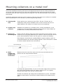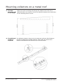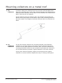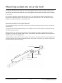
1
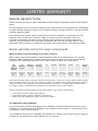
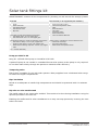
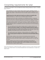
Solar Split System
Installation Manual
Hotflo Glass Lined Tank, E-Frost Collector, Gas and
Electric Boost
•
Must be installed, commissioned and serviced by an authorised
person in accordance with all applicable local rules and regulations.
•
Power supply must be available to the system at all times
Limited Warranty
Rinnai solar warranty summary table
Solar Collector
Domestic Application
Commercial Application
Parts
7 years
5 years
Labour
1 year
1 year
rinnai infinity:
Domestic models (white)
Domestic Application
Commercial Application
Parts
10 years pro rata
1,500 hours or 1 year*
Labour
3 years
1,500 hours or 1 year*
Parts
3 years
1,500 hours or 1 year*
Labour
3 years
1,500 hours or 1 year*
Domestic Application
Commercial Application
Parts
12 years pro rata
5,000 hours or 3 years*
Labour
3 years
1,500 hours or 1 year*
Parts
5 years
1,500 hours or 1 year*
Labour
3 years
1,500 hours or 1 year*
Domestic Application
Commercial Application
Parts
5 years
3 years
Labour
3 years
3 years
Parts
1 year
1 year
Labour
1 year
1 year
Heat Exchanger
All Other Parts
rinnai infinity:
Commercial models (silver)
Heat Exchanger
All Other Parts
* Whichever comes first
storage tank
Tank
All Other Parts*
* Pumps, controllers, valves etc.
All terms of the warranty are effective from the date of installation of the Rinnai solar system.
Rinnai New Zealand Limited (Rinnai) reserves the right to verify this date by requesting a copy
of the Certificate of Compliance obtained by local building authority inspection of the system.
Domestic vs. commercial application
The reason for distinguishing between a domestic and commercial application is because the
expected life of a system is directly related to the hours of use.
A domestic application is defined as an installation that serves a single residential dwelling
which is not used for commercial purposes, such as a hair salon, catering kitchen, motel or
communal care facility.
All other installations are defined as a commercial application.
Limited Warranty
General warranty terms
Rinnai reserves the right to make modifications and change specifications and its parts without
notice.
For the purposes of the Consumer Guarantees Act 1993, Rinnai only guarantees the availability
of repair facilities and spare parts for the express warranty periods recorded in the Rinnai Solar
Collector Warranty Table.
If the Rinnai solar system is being acquired for personal, domestic or household use, this
warranty does not limit any consumer rights or guarantees that may apply under the
Consumer Guarantees Act 1993. If the product is being acquired for the purposes of a
business, the provisions of the Consumer Guarantees Act 1993 do not apply and no other
warranties (either express or implied by law) apart from those stated in this warranty apply.
Rinnai warranty terms for solar components
Water quality for Rinnai Infinity and solar collectors
Water quality outside the maximum recommended limits (as set down below) will void this
warranty. Water quality tests must be carried out at the customer’s own cost but Rinnai will
reimburse any reasonable test costs where water quality is within the limits tabled.
TDS
(Total
Dissolved
Solids)
Total
Hardness
CaCO3
Alkalinity
(as CaCO3)
Dissolved
(free) CO2
pH
Chlorides
Magnesium
Sodium
Iron
Langelier
Index
Up to 600
mg/L or
ppm
Up to 200
mg/L or
ppm
Up to 200
mg/L or
ppm
Up to 25
mg/L or
ppm
6.5-8.5
Up to 300
mg/L or
ppm
Up to 10
mg/L or ppm
Up to 150
mg/L or
ppm
Up to 1
mg/L or
ppm
Between
-1.0-0.8
Most metropolitan water supplies fall within these limits. If you are unsure about water quality,
please contact Rinnai and we will provide you with the details of an authorised agency able to
test your water for compliance to Rinnai standards. If sludge or foreign matter is present in
the water supply, a suitable filter should be incorporated in the water supply.
Some examples of water quality issues where water may need to be treated:
•
•
•
Hard water (areas including Wanganui)
Aggressive water (areas including Christchurch)
Both hard and aggressive water (some bore water)
In relation to solar collectors
E-Frost collectors are warranted against frost damage caused by temperatures down to and
including -15 °C where power is available to the system and the system is configured for low
temperature mode (factory default).
It is conditional that power is available and switched on. Failure due to lack of power supply or
changes to the temperature mode settings are not covered.
Limited Warranty
In relation to storage tanks
The following exclusions apply:
•
Accessibility
Where the cylinder is not easily accessible for maintenance and replacement, this warranty
will not cover any additional costs caused by access difficulty
•
Leaks
To the fullest extent permitted by law, this warranty does not cover any consequential loss
resulting from leaks to a cylinder. Accordingly it is important that a suitably drained catch
pan is fitted where damage could be caused by discharge from the cylinder.
Warranty exclusions
The following exclusions may cause the warranty to become void and will result in a service
charge and costs of parts (if required).
1. Accidental damage and acts of God.
2. Failure due to abuse or misuse, improper maintenance or improper storage.
3. Failure due to incorrect or unauthorised installations.
4. Failure or damage caused by alterations, service or repair work carried out by persons
other than Rinnai service persons or service centres.
5. Where the solar component has failed directly or indirectly as a result of poor water quality
outside the limits specified.
6. Where it is found that there is no fault with the solar component(s) and the issue is related
to the installation or failure due to lack of power supply.
7. Subject to any statutory provisions to the contrary, Rinnai does not accept:
a. liability for consequential damage or any incidental expenses resulting from any
breach of the warranty,
b. claims for damage to building or any other consequential loss either directly or
indirectly due to leaks from the solar components or any other faults.
G12/AS2 durability
As required by the New Zealand Building Code compliance document G12/AS2, clause 7.2.3, in
respect of the durability of the solar system components supplied by Rinnai, Rinnai makes the
following statements.
a. The collector mounting rails have a durability of fifteen years provided they are kept clear
of debris such as leaves.
B. All other components of the system supplied by Rinnai may require maintenance and/or
replacement before fifteen years.
Contents
Introduction
6
Suitability for use
6
Solar collector fittings kits
7
Solar tank fittings kit
8
Cylinder location
9
Cylinder connections
10
Mounting the solar controller and pump
11
Mounting collectors on the roof - general
13
Mounting collectors on a metal roof
15
Mounting collectors on a tile roof
18
Fitting connecting pipes and sensor lead
19
Supplementary boosting - gas
20
Supplementary boosting - electric
21
Commissioning the solar system
22
Consenting requirements for solar
23
WARNING
Improper installation, adjustment, alteration, service or maintenance
can cause property damage, personal injury or loss of life.
For assistance or additional information contact Rinnai on
0800 RINNAI (0800 746 624).
Introduction
This manual is intended to be used by Rinnai accredited solar installers, who have a good
understanding of the different types of solar systems and how they operate.
The information contained is designed to reinforce information from the TradeSmart Solar
Training Course, provide an understanding of the Rinnai Solar System, its suitability for use
and high level instructions for installation.
This manual should be used in conjunction with the following codes and standards:
• AS/NZS 3500.4 (Heated Water Services)
Section 5 - General Installation
Section 6 - Solar
•
G12/AS2 (DBH Acceptable Solution for Solar Installation)
Suitability for use
Water quality
Requirements must meet the standards for Rinnai solar products (refer warranty information).
Hard or aggressive water will need to be treated in order to use this product.
Water pressure
The flowing water pressure in the dwelling needs to exceed the height of the solar collectors.
For example, of the highest point of the solar collector is 7 m above the incoming water, then
the water pressure needs to exceed 70 kPa to keep the collectors full.
Maximum water pressure
= 1000 kPa
Roof pitch and condition
E-Frost collectors perform best at roof pitches ≥ 20°. At lesser pitches performance will be
degraded. This manual does not cover installations that may require frames for flat, side, or
reverse pitch roofs.
Any damage to the roof must be repaired prior to installation of the solar collectors.
Pumped systems only
E-Frost collectors are not suitable for close coupled hot water solar systems.
Rinnai New Zealand Limited
E-Frost Solar Collector Split System
Install Manual: 11497-A
Solar collector fittings kits
These are all the components for plumbing and mounting collectors on the roof.
Included
Not included (to be supplied by the Installer)
•
•
•
•
•
•
•
•
All Plumbing Fittings
Air Release Valve
Hot Sensor Temperature Pocket
15 m of Hot Sensor Lead
Angled Mounting Rails for Panels
Straps
M5 Fasteners (guide stoppers for panels)
Mounting Fasteners
Hot outlet connection
The Rinnai standard mounting rails are for arrangements where the hot outlet connection is
on the top right hand corner. If you have an arrangement that requires a top left hot outlet
connection you will need a different top mounting rail. This can be purchased as an accessory
from Rinnai.
Stainless steel straps for tile roofs
G12 requires stainless steel straps for tile roofs. The Split System Solar Fittings Kits have
galvanised straps as standard. If collectors are being installed on a tile roof, stainless steel
straps can be purchased as an accessory item.
Example of the solar collector fittings for a two solar collector installation
Rinnai New Zealand Limited
E-Frost Solar Collector Split System
Install Manual: 11497-A
Solar tank fittings kit
SOLKITPUMPGE1 contains all the components for plumbing on and around the storage cylinder.
Included
Not included (to be supplied by the Installer)
•
•
•
•
•
•
•
•
•
•
•
•
•
Pump
Solar Controller
Cold Outlet Fittings
Cold Sensor Lead
Dip Tube
Crox Nuts to make the following connections:
•
Cold Water Inlet: 20 mm copper pipe
•
TPR Valve Drain Line: 15 mm copper pipe
Compression Fittings to make the following connections:
•
Cold Inlet to Pump: 12 mm (od) copper tube
•
Pump to Solar Panel: 12 mm (od) copper tube
•
Solar Panel to Storage Cylinder: 12 mm (od) copper
tube
Pressure Limiting Valve
Cold Water Expansion Valve
Filter
Shut-Off Valves
Catch Pan
Tempering Valve
Seismic Restraint
Timer for Electric Element
Copper tube or insulation to connect between the:
•
Cold Inlet and Pump
•
Pump and Solar Panel
•
Solar Panel and Cylinder Return
(od = outside diameter)
Pump provided in kit
Laing S1-15/700B 230V pump or Grundfos UP15-14B.
A powerful pump is not needed in a standard Rinnai solar system as the pump is only required
to circulate water slowly through the panels to maximise solar efficiency.
Tempering valve
Ensure this is suitable for use with solar systems. Many suppliers have a dedicated solar range
to handle the higher temperatures.
Pipe insulation
Needs to be adequate to handle high temperatures and should be protected with UV resistant
tape.
Dip tube to solar enable tank
The Hotflo tanks do not come solar enabled. This needs to be done during installation using the
dip tube provided in the tank kit.
Enabling the Hotflo tank for solar installations is an easy one step process by inverting the riser
tube in the tank.
Rinnai New Zealand Limited
E-Frost Solar Collector Split System
Install Manual: 11497-A
Cylinder location
Inside or
outside
The Rinnai Glass Lined storage cylinders are suitable for mounting either
inside or outside.
Relevant
regulations
Cylinders should be installed to AS/NZS3500.4, with reference to G12/AS1
where appropriate.
Base
requirements
Cylinders should be installed on a flat level base of sufficient strength to
support the weight of the water heater when full. It must also be suitably
restrained against seismic activity.
Access to
cylinder
Cylinders should not be located where they will be difficult to remove, such
as in attic spaces or built into cupboards or shelves. Tank durability is part
of B2/AS1 1.2.1c) where there is a requirement that there is no removal of
building elements in order to gain access.
Where a cylinder is not easily accessible for maintenance and replacement,
the Rinnai Warranty will not cover any additional costs caused by access
difficulty. This is important for glass lined tanks where access is required to
change the anode at the top of the cylinder.
Catch pan
It is important a suitably drained catch pan is fitted where damage could be
caused by discharge from the cylinder.
The Rinnai Warranty does not cover any consequential loss from leaks to
the cylinder if a catch pan isn’t installed.
Electrical
connections
Timer for
electric boost
systems
▪
A single phase 3 pin power point is required to power the solar pump
and controller
▪
If electric boost is used, a 16 Amp power supply from the distribution
board will be required to boost the element
▪
If gas boost is used, a second power point will be required to power the
Rinnai Infinity
▪
Ensure there are no connections to the ripple relay
A timer1 on the 16 Amp power circuit is required to control the electric
boost to ensure maximum solar gain. There are many different models
of timer available, a straight pre-programmed timer, or with an over-ride
button to allow the customer to initiate a boost at times of low solar gain.
It is important to discuss the timer with the customer as they will need to
have one installed that will suit their hot water requirements.
1 Merlin Gerin (IHP+1C 18 mm) or PDL 7 Day Electronic Timer
Rinnai New Zealand Limited
E-Frost Solar Collector Split System
Install Manual: 11497-A
Cylinder connections
Pressure
limiting valve
▪
▪
Rinnai Glass Lined 180 litre
Rinnai Glass Lined 270 and 340 litre
- 700 kPa
- 500 kPa
Cold water
pressure relief
valve
▪
▪
Rinnai Glass Lined 180 litre
Rinnai Glass Lined 270 and 340 litre
- 850 kPa approximately
- 700 kPa approximately
Temperature
& pressure
relief valve
(TPR)
▪
▪
Rinnai Glass Lined 180 litre
Rinnai Glass Lined 270 and 340 litre
- 1000 kPa [supplied with cylinder]
- 850 kPa [supplied with cylinder]
Drain valve
Provision must be made to drain the cylinder if required for servicing.
Drain lines
These must be installed in accordance with AS3500 and or G12/AS1. G12 is
available online at no cost from:
www.dbh.govt.nz/building-code-compliance-documents
Tempering
valve
During times of high solar gain water temperatures in solar systems can
become very high. A tempering valve will be required. Ensure that it is
suitable for use with solar systems. Many suppliers have a dedicated solar
range to handle the higher temperatures.
Rinnai New Zealand Limited
10
E-Frost Solar Collector Split System
Install Manual: 11497-A
Mounting the solar controller and pump
1. Mount the solar controller in a suitable position on the side of the cylinder or adjacent wall
using suitable fasteners.
2. Change position of the riser tube to solar enable the Hotflo storage cylinder using the dip
tube provided in the tank fittings kit.
- Select which upper hot outlet will be used for the hot solar return
- Invert the riser tube using the wire tool supplied
3. Fit the plumbing fittings as shown below and in the drawing on the back of the fittings kit
Rinnai New Zealand Limited
11
E-Frost Solar Collector Split System
Install Manual: 11497-A
Mounting the solar controller and pump
4. Run a piece of insulated 12 mm od copper tube from the cold inlet to the pump. Ensure the
pump is installed correctly with the impeller in a vertical not horizontal position.
5. Uncoil the cold temperature sensor in the control box and feed it out of the gland in the
bottom of the control box. Do not attach it to the pipe work until the commissioning stage.
6. Set pump controller for panel type. This controls the hot water circulation for frost
protection.
Solar Control Box with Switch Positions Marked
Solar Controller Settings
Hot Water
Circulation
CIRC/DUMP
FPOFF/FPON
CIRC
FPON
Other settings are not recommended.
7. There are three power warning labels (see below) supplied with the solar collector fittings
kit. Place these adjacent to the power main switch, the circuit breaker controlling the outlet
into which the pump is connected and on the cover of the control box.
Ensure the consumer is aware that the system frost protection will be reduced if the power
is not available.
Frost Protection - Electricity Required Label
IMPORTANT
This house has a solar panel which requires power to
prevent damage in freezing conditions.
DO NOT DISCONNECT POWER if there is a likelyhood of
freezing without draining the panel.
Contact your solar supplier or Rinnai Service agent who
can drain the panel safely.
Phone: 0800 RINNAI / 0800 746 624
8. Do not connect the power lead to the power supply at this stage.
Rinnai New Zealand Limited
12
E-Frost Solar Collector Split System
Install Manual: 11497-A
Mounting collectors on the roof - general
Roof sizing and
collector weight
Each Rinnai solar collector is approximately 2 m tall by 1 m wide. Select
a location with sufficient space for the collectors and associated plumbing
connections.
The collectors weigh approximately 40 kg each and due care and skill
should be taken when lifting them onto the roof.
Roof inspection
required before
installation
Inspect the roof before commencing installation and draw the attention of
the customer to any existing damage. Arrange repair before installation.
Collector angle
and positioning
Mount the collectors on a suitable North facing roof surface. Select
a location where shading from adjacent buildings and trees will be
minimised.
As per G12, AS2, Figure 2, paragraph 4.1
Solar water heaters must be located away from the edge of the gable roof
structure outside the high pressure wind zone as shown.
In order to assist circulation and prevent air-locking, each collector must
slope upwards 8-10 mm from inlet to outlet as shown.
The mounting rails supplied in the collector fittings kit will enable this to
occur.
Hot
connection
Cold
connection
mm
slope upwards 8-10
Each collector must
Collectors must be securely fastened to the roof, refer following pages.
Rinnai New Zealand Limited
13
E-Frost Solar Collector Split System
Install Manual: 11497-A
Mounting collectors on the roof - general
Pipe
connections
between
collector and
tank
Hot collectors
WARNING
▪
Connecting pipes should pitch up continuously from the tank to the
collector to prevent air-locking
▪
Insulation should be of a suitable material to withstand high
temperatures in solar systems and be protected with UV resistant tape
or other coating
▪
Maximum total flow and return pipe length between cylinder and
collector is 50 m
The surface and frames can become extremely hot. Collectors should be
kept covered while handling and suitable protective clothing including
gloves must be used to prevent burns.
Keep collectors covered until commissioning and leak testing of the
system is complete.
Rinnai New Zealand Limited
14
E-Frost Solar Collector Split System
Install Manual: 11497-A
Mounting collectors on a metal roof
The Rinnai standard mounting rails are for arrangements where the hot outlet connection is
on the top right hand corner. If you have an arrangement that requires a top left hot outlet
connection you will need a different top mounting rail. This can be purchased as an accessory
from Rinnai.
Unpainted galvanised roofs will require painting under the area where the collector is installed
and any subsequent run off areas (e.g. down the guttering below).
1. Check purlin
size
Check purlins are a minimum size of 50 x 50 mm. If there are no
sufficiently sized purlins available at the correct centres they can be
added between the rafters or trusses at the correct spacing.
2. Position top
collector
Establish the position at a suitable purlin, usually identified by a row
of fasteners. The assembled collectors should cross as many rafters as
possible and be evenly distributed across them.
3. Fasten top
mounting rail
Fasten with the bottom edge level and horizontal as shown below. Use a
minimum of 8 x 8 gauge fasteners per collector. Two are secured into the
purlin with the balance either into the purlin or metal roof cladding.
Each fastener should have a suitable EDPM or similar washer under its
head and between the rail and roofing material. There should be no metal
to metal contact between the roof and rail.
il
Top mounting ra
Level
4. Mark
position for
strap hooks
and secure
Measure down the roof from each end of the top rail and mark the
position for the strap hook as follows:
Fit strap hook approximately 75 mm in from each edge of the mounting
rail. Screw both straps to the roof using a minimum of 4 x 8 gauge
fasteners per strap. Trim off any excess length.
At least one fastener per strap must be attached to a purlin. Use EDPM
washers underneath to avoid direct contact between the strap and the
roof.
Rinnai New Zealand Limited
15
E-Frost Solar Collector Split System
Install Manual: 11497-A
Mounting collectors on a metal roof
5. Fit lower
mounting rail
to the straps
Fasten the lower mounting rail through the straps to the roof and in
additional places as required. Check the distance between the inside faces
of the mounting rails is correct.
6. Fit additional Fit additional straps so there are two straps per collector. Each fastener
straps as
should be sealed with suitable washers, both under the head of the
required
fastener and between the rail and roof, as shown below.
Rinnai New Zealand Limited
16
E-Frost Solar Collector Split System
Install Manual: 11497-A
Mounting collectors on a metal roof
7. Fit
collectors
To assist in fitting the collectors there are a series of M5 threaded holes
along the mounting rails. In the solar collector fittings kit are M5 fasteners.
These should be inserted into the holes in the rail before the collectors are
fitted. These will act as ‘stoppers’.
Fit the collectors into the mounting rails. The stoppers will position the
panels at the right height for the slots to align so the mounting fasteners
can insert easily. The stoppers should be removed after the collectors are
fitted.
Use lower holes
8. Fit
additional
collectors
Fit the first collector between the mounting brackets using fasteners
supplied, do not fully tighten at this point. Fit the collector connectors
for two or three panel systems to the first panel. Fit second collector by
inserting the header tubes into the connectors and attach the collector to
the rail with fasteners provided. Tighten fasteners on the first collector.
Firmly push collectors together, tighten connectors and then tighten
fasteners on second collector. Repeat from step 7 if fitting a third panel.
Rinnai New Zealand Limited
17
E-Frost Solar Collector Split System
Install Manual: 11497-A
Mounting collectors on a tile roof
The Rinnai standard mounting rails are for arrangements where the hot outlet connection is
on the top right hand corner. If you have an arrangement that requires a top left hot outlet
connection you will need a different top mounting rail. This can be purchased as an accessory
from Rinnai.
G12 requires stainless steel straps for tile roofs. The Split System Solar Fittings Kits have
galvanised straps as standard. If collectors are being installed on a tile roof, stainless steel
straps can be purchased as an accessory item.
Determine position for top mounting rail
The assembled collectors should cross as many rafters as possible and be evenly distributed
across them.
The top rail should be approximately in the middle of a line of tiles. Mark a horizontal line at
the determined position.
Measure down the roof from the top line for the respective collector. Check that the lower
line does not coincide with an edge of tiles. If necessary adjust the position of the upper line
slightly to prevent this happening.
The procedure is the same as for the metal roof with the exception that the top mounting rail
is also fastened using straps. Additionally there should be no need to use spacers to prevent
the rails touching the tile roofing.
Tile removed
m
0m
8
19
st
Fro
E-
Rinnai New Zealand Limited
tor
ec
ll
co
Four fasteners
Bottom edge of top rail
to be level
18
E-Frost Solar Collector Split System
Install Manual: 11497-A
Fitting connecting pipes and sensor lead
All penetrations through the roof for connecting pipes and hot sensor lead should be made
using suitable sealing boots such as dektites.
1. Attach
plumbing
fittings
Run piping
and insulate
Attach necessary plumbing fittings to the collector(s) as shown below.
Compression fittings are designed for 12 mm outside dimension (od)
copper tube.
Run and insulate piping between the pump outlet and bottom left corner
of the collector(s).
Run and insulate piping between hot sensor lead connector on top right
hand corner of collectors to the hot return at the storage cylinder.
The piping should pitch continuously upwards to the collectors to prevent
air-locking.
2. Insert hot
sensor lead
Insert hot sensor lead into the pocket on the fitting on the top right
corner of the collector(s) and secure in place with suitable high
temperature silicon.
The other end of the assembly is run through a fitting on the bottom side
of the solar pump and controller box and attached to the mating electrical
connector on the solar controller.
Longer leads of 30 m length are available from Rinnai as an accessory,
or the lead can be terminated and extended using two core sheathed
(double insulated) flex with conductors of 0.5 mm2 (minimum cross
section area).
Rinnai Solar Collector Fittings Kit Assembly - Two Collectors
Hot sensor lead
Rinnai New Zealand Limited
19
E-Frost Solar Collector Split System
Install Manual: 11497-A
Supplementary boosting - gas
Install a Rinnai continuous flow water heater using a flow diversion valve as shown below. The
water heater must be set to 75 oC.
All Rinnai Infinity units installed in a solar system require a flow diversion valve and a
dipswitch change to the required 75 oC. (Remember ‘B to Boiler’ when setting up the flow
diversion valve).
Rinnai water controllers cannot be used with Rinnai Infinity units connected to solar systems as
the:
•
•
Hot water does not always pass through the Rinnai Infinity
Rinnai Infinity preset dip switch setting of 75 oC is unable to be adjusted.
Recommended system layout using a Rinnai Infinity and flow diversion valve
Configuring the System to Protect for Legionella
If the system is configured according to the details above it will meet the requirements of
the Acceptable Solution G12/AS2 for protection against Legionella. This states that “the
instantaneous water heater must heat all water passing through it to not less than 70 °C.”
Rinnai New Zealand Limited
20
E-Frost Solar Collector Split System
Install Manual: 11497-A
Supplementary boosting - electric
All Rinnai storage cylinders come pre-equipped with electric elements and thermostats.
Electrical connections
The cylinders are pre-wired. A 20 mm mounting hole for conduit
termination is provided under the element cover. A 2 way terminal
block is provided for connection of Active and Neutral wires
(pictured) and a brass terminal block is provided for connection of
the earth cable.
Timer
To gain the most effective solar contribution the element is usually
controlled by a timer placed in the circuit as shown below. There are
a number of commercially available timers1, consult your electrical
supplier.
Ensure the timer contacts have sufficient rating to switch the load.
This will be approximately 15 Amps for a 3600 Watt element.
1 Examples: Merlin Gerin (1HP+1C 18 mm) or PDL 7 Day Electronic Timer
Representation of how a timer would be set up in a circuit
Configuring the System to Protect for Legionella
G12/AS2 states that effective Legionella protection can be gained by heating the cylinder to at
least 60 oC once a day, and the element is in the bottom 20% of the water tank (by volume)
and no more than 150 mm from the bottom of the tank.
To meet this requirement and provide a sufficient quantity of hot water for the customer, the
timer can be set to provide electricity to the cylinder from 9pm to 5am. This will ensure a full
tank of hot, Legionella free water every morning.
Rinnai New Zealand Limited
21
E-Frost Solar Collector Split System
Install Manual: 11497-A
Commissioning the solar system
Until system filling and commissioning is complete:
WARNING
•
Keep solar panels covered
•
Do not plug in the solar controller / pump or connect a power supply to boost the
element until step 6
1. If a gas boost is fitted, open the inlet and outlet water valves at the Rinnai Infinity but do
not connect the power supply at this point.
2. Open a hot tap at the sink.
3. Open the cold water inlet to the storage cylinder.
4. Keep the hot tap open until non-aerated water appears at the sink.
5. Taking care to avoid potentially scalding water, open the air bleed valve on the temperature
sensor pocket on the top right hand corner of the solar panel(s).
6. Plug in the power lead from the solar controller / pump. If the hot temperature sensor is
9 oC hotter than the cold temperature sensor the pump should start. If this is not the case,
cool down the cold temperature sensor in a cup of ice. If this is still not sufficient to create
the 9 oC differential, a spare hot sensor lead can temporarily be connected to the pump
controller and warmed until the pump starts.
7. Leave the air bleed valve open with the pump running until non-aerated water appears at
the bleed valve. Close the air bleed valve.
8. The coverings can now be removed from the solar panel(s).
9. Tape the cold sensor to the T on the inlet of the cylinder. Fit suitable insulation material
over the sensor and fasten in place.
10. Fit the pump and controller cover.
11. For an electric boost system, program the timer as required, set the thermostat to between
60 and 70 oC and replace the element cover.
12. For a gas boost system, connect the Rinnai Infinity to power and gas, and commission in
accordance with the instructions supplied with the water heater.
Rinnai New Zealand Limited
22
E-Frost Solar Collector Split System
Install Manual: 11497-A
Consenting requirements for solar
The following information is from the EECA Solar Water Heating Guidebook, Version 1, October
2006, Section 2.
The installation of a solar hot water heating system requires a Building Consent
because solar water heating systems interact with potable water supplies and can
involve heavy loads on roof structures if the hot water cylinder is mounted on the
roof.
A Building Consent is also required where there is a change to a potable water
supply system and to the heat source. Other permits may be required to cover
electrical alterations, or where there is a building height restriction.
All plumbing work will require certification by a craftsman plumber. A registered
electrician will need to certify any electrical work that may be needed. Certifications
may be in the form of a Producer Statement as required by the Building Consent.
Solar water heating installers should ensure that any necessary Building Consents
are obtained and adhered to. An installer must then be able to demonstrate to the
Consent Authority that the installation meets the requirements of the New Zealand
Building Code.
•
For new dwellings, the solar water heating system is usually included in the
overall consent for the building. In this case the plumbing approval is usually
done by the designer, specifier or the plumbing contractor. Structural approval is
done during the process of approving the design of the trusses with the trusses
merchant, by taking into account the specific load of the hot water cylinder (not
applicable if the system does not have a cylinder on the roof).
•
For installing solar water heating on existing dwellings, the installers usually
provide a signed Producer Statement confirming they have installed the solar
water heating system according to the requirements of the New Zealand Building
Code.
If the hot water cylinder is not on the roof, the Building Consent should be
submitted as a minor plumbing alteration. However, when the cylinder is on the
roof, the city council will require evidence that the existing structure can cope with
the load.
System suppliers often provide pre-prepared supporting documentation to
accompany an application to help installers obtain Building Consents with the
minimum effort. The documentation may include acceptable structural support
arrangements for specific system models.
Rinnai has developed a G12 AS2 Rinnai Solar Compliance document to assist with the consent
process. This can be found on our technical website www.rinnai-tradesmart.co.nz within the
Solar section.
Rinnai New Zealand Limited
23
E-Frost Solar Collector Split System
Install Manual: 11497-A
Consumers:
Installers:
0800 RINNAI (746 624)
0800 TO RINNAI (86 746 624)
Address:
105 Pavilion Drive, Airport Oaks, Mangere, Manukau
PO Box 53177, Auckland Airport, Manukau 2150
Phone:
Fax:
(09) 257 3800
(09) 257 3899
Email:
Websites:
[email protected]
www.rinnai.co.nz and www.rinnai-tradesmart.co.nz
All Rinnai appliances meet or exceed the safety standards required by New Zealand
gas and electrical regulations.
Rinnai is constantly improving its products and as such information and
specifications are subject to change or variation without notice.