1
• SAFETY PRECAUTIONS •
(Always read these instructions before using this equipment.)
Before using this product, please read this manual and the relevant manuals introduced in this manual
carefully and pay full attention to safety to handle the product correctly.
The instructions given in this manual are concerned with this product. For the safety instructions of the
programmable controller system, please read the CPU module user's manual.
In this manual, the safety instructions are ranked as "DANGER" and "CAUTION".
DANGER
Indicates that incorrect handling may cause hazardous conditions,
resulting in death or severe injury.
! CAUTION
Indicates that incorrect handling may cause hazardous conditions,
resulting in medium or slight personal injury or physical damage.
!
Note that the ! CAUTION level may lead to a serious consequence according to the circumstances.
Always follow the instructions of both levels because they are important to personal safety.
Please save this manual to make it accessible when required and always forward it to the end user.
[Design Instructions]
!
DANGER
• For data change, program change, and status control made to the PLC which is running from a
Personal computer, configure the interlock circuit externally so that the system safety is
ensured. The action to be taken for the system at the occurrence of communication errors
caused by such as loose cable connection must be determined for online operation of PLC from
Personal computers.
!
CAUTION
• Be sure to read the manual careful and exercise an appropriate amount of caution connecting to
PLC CPU and performing online operations (PLC CPU program change during RUN, forced
input/output operation, RUN-STOP or other operation condition changes, remote control
operation) while the personal computer is operating.
Regarding the PLC CPU program change during RUN (Online change), the program may be
corrupted or have other problems depending on operation conditions. Exercise the appropriate
amount of caution with regard to the Caution points in the Reference Manual.
• Please refer to the manual of each module for online module change and swap module during
run, since there is restriction on the exchangeable module.
The texts, illustrations, diagrams and examples in this manual are only
intended as aids to help explain the functioning, operation, use and
programming of the GX IEC Developer IEC programming and
documentation system.
For using and usage of this software only the user his own is
responsible.
If you have any questions regarding the installation and operation of the
software described in this manual, please do not hesitate to contact your
sales office or one of your Mitsubishi distribution partners.
You can also obtain information and answers to frequently asked questions
from our Mitsubishi website under
www.mitsubishi-automation.de.
The GX IEC Developer software is supplied under a legal license
agreement and may only be used and copied subject to the terms of this
License Agreement.
No part of this manual may be reproduced, copied, stored in any kind of
information retrieval system or distributed without the prior express written
consent of MITSUBISHI ELECTRIC.
MITSUBISHI ELECTRIC reserves the right to change the specifications of
its products and/or the contents of this manual at any time and without
prior notice.
The IEC 61131.1 standard cited in this manual is available from the
publishers Beuth Verlag in Berlin (Germany).
ã October 2008
Beginner's Manual for
MELSOFT GX IEC Developer
Art. no.: 43596
Version
Changes / Additions / Corrections
A
03/1995 ME
First issue
B
05/1996 ME
Software update
C
07/1997 ME
Software update
D
01/1998 ME
Software update
E
08/2000 pdp-rs
Update to software version 2.40
F
06/2001 pdp-rs
Update to software version 4.00
G
05/2002 rs/pdp
Update to software version 5.00
H
09/2003 ow/pdp
Update to software version 6.00
I
09/2004 ow/pdp
Update to software version 6.10
J
09/2005 ow/pdp
Update to software version 7.00
K
11/2006 ow/pdp
Update to software version 7.01
L
09/2007 ow/pdp
Update to software version 7.02
M
10/2008 ow/pdp
Update to software version 7.03
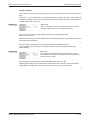
Typographic Conventions
Use of notes
Notes containing important information are clearly identified as follows:
NOTE
Note text
Use of examples
Examples containing important information are clearly identified as follows:
Example
Example text
쑶
Numbering in figures and illustrations
Reference numbers in figures and illustrations are shown with white numbers in a black circle
and the corresponding explanations shown beneath the illustrations are identified with the
same numbers, like this:
� � � �
Procedures
In some cases the setup, operation, maintenance and other instructions are explained with
numbered procedures. The individual steps of these procedures are numbered in ascending
order with black numbers in a white circle, and they must be performed in the exact order
shown:
햲 Text
햳 Text
햴 Text
Footnotes in tables
Footnote characters in tables are printed in superscript and the corresponding footnotes
shown beneath the table are identified by the same characters, also in superscript.
If a table contains more than one footnote, they are all listed below the table and numbered in
ascending order with black numbers in a white circle, like this:
햲
Text
햳
Text
햴
Text
Character formatting and orientation aids
Menu names, menu commands, submenu commands, and dialog box options are printed in
boldface type. Examples: The menu item New in the menu Project or the options PLC interface and Computer Link in the dialog box Transfer-Setup.
Please keep this manual in a place where it is always available for the users.
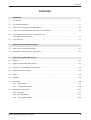
Contents
Contents
1
Introduction
1.1
This manual… . . . . . . . . . . . . . . . . . . . . . . . . . . . . . . . . . . . . . . . . . . . . . . . . . . . . . . . . . . . . . . . . . . .1-1
1.2
The Reference Manual… . . . . . . . . . . . . . . . . . . . . . . . . . . . . . . . . . . . . . . . . . . . . . . . . . . . . . . . . . .1-1
1.3
If you are not yet familiar with MS Windows … . . . . . . . . . . . . . . . . . . . . . . . . . . . . . . . . . . . . . . . . . .1-1
1.4
If you are not yet familiar with the IEC 61131-3 standard… . . . . . . . . . . . . . . . . . . . . . . . . . . . . . . . . 1-1
1.5
If you already have IEC 61131-3 experience and
want to get to work right away… . . . . . . . . . . . . . . . . . . . . . . . . . . . . . . . . . . . . . . . . . . . . . . . . . . . . .1-1
1.6
If you get stuck… . . . . . . . . . . . . . . . . . . . . . . . . . . . . . . . . . . . . . . . . . . . . . . . . . . . . . . . . . . . . . . . . .1-2
2
Getting to Know GX IEC Developer
2.1
What's New in GX IEC Developer? . . . . . . . . . . . . . . . . . . . . . . . . . . . . . . . . . . . . . . . . . . . . . . . . . . .2-1
2.2
Introduction to the IEC 61131-3 Standard. . . . . . . . . . . . . . . . . . . . . . . . . . . . . . . . . . . . . . . . . . . . . .2-2
3
Basic Terms Used in IEC 61131-3
3.1
Projects . . . . . . . . . . . . . . . . . . . . . . . . . . . . . . . . . . . . . . . . . . . . . . . . . . . . . . . . . . . . . . . . . . . . . . . .3-1
3.2
Program Organisation Units (POUs) . . . . . . . . . . . . . . . . . . . . . . . . . . . . . . . . . . . . . . . . . . . . . . . . . .3-2
3.3
Programs, Function Blocks and Functions . . . . . . . . . . . . . . . . . . . . . . . . . . . . . . . . . . . . . . . . . . . . .3-3
3.4
Parameters and Instancing . . . . . . . . . . . . . . . . . . . . . . . . . . . . . . . . . . . . . . . . . . . . . . . . . . . . . . . . .3-4
3.5
Tasks . . . . . . . . . . . . . . . . . . . . . . . . . . . . . . . . . . . . . . . . . . . . . . . . . . . . . . . . . . . . . . . . . . . . . . . . . .3-5
3.6
Variables . . . . . . . . . . . . . . . . . . . . . . . . . . . . . . . . . . . . . . . . . . . . . . . . . . . . . . . . . . . . . . . . . . . . . . .3-6
3.7
Data Types. . . . . . . . . . . . . . . . . . . . . . . . . . . . . . . . . . . . . . . . . . . . . . . . . . . . . . . . . . . . . . . . . . . . . .3-9
3.8
3.7.1
Simple Types . . . . . . . . . . . . . . . . . . . . . . . . . . . . . . . . . . . . . . . . . . . . . . . . . . . . . . . . . . . . . .3-9
3.7.2
Complex Data Types . . . . . . . . . . . . . . . . . . . . . . . . . . . . . . . . . . . . . . . . . . . . . . . . . . . . . . .3-10
Programming Languages . . . . . . . . . . . . . . . . . . . . . . . . . . . . . . . . . . . . . . . . . . . . . . . . . . . . . . . . .3-11
3.8.1
Networks . . . . . . . . . . . . . . . . . . . . . . . . . . . . . . . . . . . . . . . . . . . . . . . . . . . . . . . . . . . . . . . .3-11
3.8.2
The Text Editors . . . . . . . . . . . . . . . . . . . . . . . . . . . . . . . . . . . . . . . . . . . . . . . . . . . . . . . . . .3-11
3.8.3
The Graphical Editors . . . . . . . . . . . . . . . . . . . . . . . . . . . . . . . . . . . . . . . . . . . . . . . . . . . . . .3-16
GX IEC Developer Beginner's Manual
IX
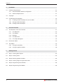
Contents
4
Installation
4.1
Hardware Requirements . . . . . . . . . . . . . . . . . . . . . . . . . . . . . . . . . . . . . . . . . . . . . . . . . . . . . . . . . . .4-1
4.1.1
Recommended Hardware Configuration. . . . . . . . . . . . . . . . . . . . . . . . . . . . . . . . . . . . . . . . .4-1
4.1.2
Software Requirements. . . . . . . . . . . . . . . . . . . . . . . . . . . . . . . . . . . . . . . . . . . . . . . . . . . . . .4-1
4.2
Copyright . . . . . . . . . . . . . . . . . . . . . . . . . . . . . . . . . . . . . . . . . . . . . . . . . . . . . . . . . . . . . . . . . . . . . . .4-1
4.3
Installing GX IEC Developer . . . . . . . . . . . . . . . . . . . . . . . . . . . . . . . . . . . . . . . . . . . . . . . . . . . . . . . .4-2
4.3.1
Installing GX IEC Developer on your hard disk. . . . . . . . . . . . . . . . . . . . . . . . . . . . . . . . . . . .4-2
4.3.2
Starting GX IEC Developer . . . . . . . . . . . . . . . . . . . . . . . . . . . . . . . . . . . . . . . . . . . . . . . . . . .4-2
4.3.3
Quitting GX IEC Developer . . . . . . . . . . . . . . . . . . . . . . . . . . . . . . . . . . . . . . . . . . . . . . . . . . .4-2
5
The User Interface
5.1
The Elements of the User Interface. . . . . . . . . . . . . . . . . . . . . . . . . . . . . . . . . . . . . . . . . . . . . . . . . . .5-1
5.1.1
The Menu Bar . . . . . . . . . . . . . . . . . . . . . . . . . . . . . . . . . . . . . . . . . . . . . . . . . . . . . . . . . . . . .5-2
5.1.2
The Toolbar . . . . . . . . . . . . . . . . . . . . . . . . . . . . . . . . . . . . . . . . . . . . . . . . . . . . . . . . . . . . . . .5-2
5.1.3
Windows . . . . . . . . . . . . . . . . . . . . . . . . . . . . . . . . . . . . . . . . . . . . . . . . . . . . . . . . . . . . . . . . .5-2
5.1.4
The Status Bar . . . . . . . . . . . . . . . . . . . . . . . . . . . . . . . . . . . . . . . . . . . . . . . . . . . . . . . . . . . .5-2
5.1.5
The Project Navigator . . . . . . . . . . . . . . . . . . . . . . . . . . . . . . . . . . . . . . . . . . . . . . . . . . . . . . .5-3
5.2
Declaration Tables . . . . . . . . . . . . . . . . . . . . . . . . . . . . . . . . . . . . . . . . . . . . . . . . . . . . . . . . . . . . . . . .5-4
5.3
The Editors . . . . . . . . . . . . . . . . . . . . . . . . . . . . . . . . . . . . . . . . . . . . . . . . . . . . . . . . . . . . . . . . . . . . .5-5
5.3.1
Using the text editors. . . . . . . . . . . . . . . . . . . . . . . . . . . . . . . . . . . . . . . . . . . . . . . . . . . . . . . .5-5
5.3.2
Using the graphical editors . . . . . . . . . . . . . . . . . . . . . . . . . . . . . . . . . . . . . . . . . . . . . . . . . . .5-6
6
Getting Started
6.1
Step 1: Creating New Projects . . . . . . . . . . . . . . . . . . . . . . . . . . . . . . . . . . . . . . . . . . . . . . . . . . . . . .6-2
6.2
Step 2: Creating Tasks. . . . . . . . . . . . . . . . . . . . . . . . . . . . . . . . . . . . . . . . . . . . . . . . . . . . . . . . . . . . .6-4
6.3
Step 3: Declaring Global Variables . . . . . . . . . . . . . . . . . . . . . . . . . . . . . . . . . . . . . . . . . . . . . . . . . . .6-5
6.4
Step 4: Creating Program Organisation Units . . . . . . . . . . . . . . . . . . . . . . . . . . . . . . . . . . . . . . . . . . .6-7
6.5
Step 5: Programming POU Headers . . . . . . . . . . . . . . . . . . . . . . . . . . . . . . . . . . . . . . . . . . . . . . . . . .6-8
6.6
Step 6: Programming POU Bodies . . . . . . . . . . . . . . . . . . . . . . . . . . . . . . . . . . . . . . . . . . . . . . . . . . .6-9
X
MITSUBISHI ELECTRIC
Contents
6.7
Programming Examples . . . . . . . . . . . . . . . . . . . . . . . . . . . . . . . . . . . . . . . . . . . . . . . . . . . . . . . . . .6-10
6.7.1
Inputs and outputs in ladder diagram language (LD) . . . . . . . . . . . . . . . . . . . . . . . . . . . . . . 6-10
6.7.2
A Sum Function in FBD Language . . . . . . . . . . . . . . . . . . . . . . . . . . . . . . . . . . . . . . . . . . . .6-12
6.7.3
I/O Signal Configuration Parameters . . . . . . . . . . . . . . . . . . . . . . . . . . . . . . . . . . . . . . . . . .6-14
6.7.4
Timers in LD/FBD/IL . . . . . . . . . . . . . . . . . . . . . . . . . . . . . . . . . . . . . . . . . . . . . . . . . . . . . . .6-15
6.7.5
Sequential Function Chart Language . . . . . . . . . . . . . . . . . . . . . . . . . . . . . . . . . . . . . . . . . .6-20
6.8
Step 7: Checking PLC Programs (syntax check) . . . . . . . . . . . . . . . . . . . . . . . . . . . . . . . . . . . . . . .6-36
6.9
Step 8: Configuring Tasks . . . . . . . . . . . . . . . . . . . . . . . . . . . . . . . . . . . . . . . . . . . . . . . . . . . . . . . . .6-37
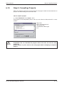
6.10 Step 9: Compiling Projects . . . . . . . . . . . . . . . . . . . . . . . . . . . . . . . . . . . . . . . . . . . . . . . . . . . . . . . .6-39
6.11 Step 10: Communications Port Setup . . . . . . . . . . . . . . . . . . . . . . . . . . . . . . . . . . . . . . . . . . . . . . . .6-40
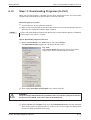
6.12 Step 11: Downloading Programs (to PLC) . . . . . . . . . . . . . . . . . . . . . . . . . . . . . . . . . . . . . . . . . . . .6-41
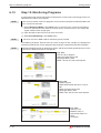
6.13 Step 12: Monitoring Programs. . . . . . . . . . . . . . . . . . . . . . . . . . . . . . . . . . . . . . . . . . . . . . . . . . . . . .6-42
6.14 Step 13: Uploading Data from the CPU. . . . . . . . . . . . . . . . . . . . . . . . . . . . . . . . . . . . . . . . . . . . . . .6-43
7
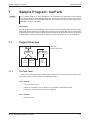
Sample Program: CarPark
7.1
Project Structure . . . . . . . . . . . . . . . . . . . . . . . . . . . . . . . . . . . . . . . . . . . . . . . . . . . . . . . . . . . . . . . . .7-1
7.1.1
The Task "Main" . . . . . . . . . . . . . . . . . . . . . . . . . . . . . . . . . . . . . . . . . . . . . . . . . . . . . . . . . . .7-1
7.1.2
The Task "Door_Operate" . . . . . . . . . . . . . . . . . . . . . . . . . . . . . . . . . . . . . . . . . . . . . . . . . . . .7-2
7.2
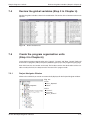
Create the new "CarPark" project (Step 1 in Chapter 6) . . . . . . . . . . . . . . . . . . . . . . . . . . . . . . . . . . . 7-2
7.3
Create the tasks (Step 2 in Chapter 6) . . . . . . . . . . . . . . . . . . . . . . . . . . . . . . . . . . . . . . . . . . . . . . . .7-2
7.4
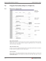
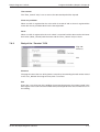
Declare the global variables (Step 3 in Chapter 6) . . . . . . . . . . . . . . . . . . . . . . . . . . . . . . . . . . . . . . .7-3
7.5
Create the program organisation units (Step 4 in Chapter 6) . . . . . . . . . . . . . . . . . . . . . . . . . . . . . . . 7-3
7.5.1
7.6
7.7
8
Project Navigator Window. . . . . . . . . . . . . . . . . . . . . . . . . . . . . . . . . . . . . . . . . . . . . . . . . . . .7-3
Program the bodies (Step 6 in Chapter 6). . . . . . . . . . . . . . . . . . . . . . . . . . . . . . . . . . . . . . . . . . . . . .7-4
7.6.1
Body of the "Control" POU . . . . . . . . . . . . . . . . . . . . . . . . . . . . . . . . . . . . . . . . . . . . . . . . . . .7-4
7.6.2
Body of the "Counter" POU. . . . . . . . . . . . . . . . . . . . . . . . . . . . . . . . . . . . . . . . . . . . . . . . . . .7-5
7.6.3
Body of the "Door_Control" POU . . . . . . . . . . . . . . . . . . . . . . . . . . . . . . . . . . . . . . . . . . . . . .7-6
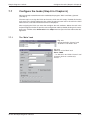
Configure the tasks (Step 8 in Chapter 6) . . . . . . . . . . . . . . . . . . . . . . . . . . . . . . . . . . . . . . . . . . . . . .7-7
7.7.1
The "Main" task . . . . . . . . . . . . . . . . . . . . . . . . . . . . . . . . . . . . . . . . . . . . . . . . . . . . . . . . . . . .7-7
7.7.2
The "Door_Operate" Task . . . . . . . . . . . . . . . . . . . . . . . . . . . . . . . . . . . . . . . . . . . . . . . . . . . .7-8
Importing
GX IEC Developer Beginner's Manual
XI
Contents
XII
MITSUBISHI ELECTRIC
Introduction
This manual…
1
Introduction
1.1
This manual…
...is a compact guide to using GX IEC Developer, suitable both for beginners and experienced
users upgrading from other systems. The manual includes explanations of the terms and
structural concepts of IEC programming and an introduction to the new IEC 61131-3 standard.
The "Getting Started" chapter provides a precise step-by-step description of how to use GX
IEC Developer, including a sample project. This executable application is used to demonstrate
the operation of the program with the help of the exercises provided in this manual.
1.2
The Reference Manual…
… contains detailed descriptions of all menus and menu options. Refer to it whenever you
need more comprehensive information on the ins and outs of the system.
1.3
If you are not yet familiar with MS Windows …
… please at least read the Windows Fundamentals section in the Windows User's Guide, or
work through the Windows Tutorial accessible through the Help menu of the Windows Program
Manager. This will teach you what you need to know about using the basic elements of MS Windows, and the operating procedures that are identical in all Windows application programs.
1.4
If you are not yet familiar with the IEC 61131-3
standard…
… please do take the time to read the "Introduction to the IEC 61131-3 Standard" chapter.
This section explains the most important new terms and concepts of this industrial standard.
A glossary of all the terms is provided in the Appendix of the Reference Manual.
1.5
If you already have IEC 61131-3 experience and
want to get to work right away…
… then you can go straight to the "Getting Started" section for immediate results. This chapter
provides clear, step-by-step descriptions of all important GX IEC Developer operations, from
creating a new project to downloading your finished program to the controller.
GX IEC Developer Beginner's Manual
1–1
If you get stuck…
1.6
Introduction
If you get stuck…
… do not despair, help is never far away! If you run up against seemingly insoluble problems, or if
you have questions about GX IEC Developer or the connected programmable controller (PLC)
configuration, please first refer to the manuals and documentation. Many answers and solutions
can also be found directly in the GX IEC Developer context-sensitive online help system, which
can always be accessed by pressing the key. Make use of the Search command in the Help
menu as well, as this will often locate the information you need. If you can't find answers to your
questions in any of these places, contact your local MITSUBISHI ELECTRIC representative or
call our European headquarters in Ratingen directly. The addresses and phone numbers are
provided on the back covers of all our manuals.
1–2
MITSUBISHI ELECTRIC
Getting to Know GX IEC Developer
What's New in GX IEC Developer?
2
Getting to Know GX IEC Developer
2.1
What's New in GX IEC Developer?
GX IEC Developer is a Windows program:
GX IEC Developer uses the graphical user interface of MS Windows for fast, intuitive operation.
This means that instead of laboriously searching through a labyrinth of program structures,
you can implement your controller applications quickly and efficiently.
GX IEC Developer increases your productivity:
The modular architecture of GX IEC Developer brings big advantages for complex programming projects. Frequently-needed program blocks and functions only need to be created once.
Thanks to the building block system you can then insert them again and again wherever and
whenever required. This significantly reduces your programming overheads, enabling you to
make major changes to your programs with just a few simple operations.
GX IEC Developer is a multi-language system:
GX IEC Developer supports programming in different languages. Several graphical and
text-based editors help you to write tailor-made programs quickly and easily, choosing the language that best suits the problem.
GX IEC Developer is your link to the IEC world:
GX IEC Developer supports the new IEC 61131-3 standard for PLC (programmable controller)
programming. This standard lays down the specifications for standardized PLC control programs.
GX IEC Developer Beginner's Manual
2–1
Introduction to the IEC 61131-3 Standard
2.2
Getting to Know GX IEC Developer
Introduction to the IEC 61131-3 Standard
IEC 61131-3 is the new international standard for PLC programs, defined by the International
Electrotechnical Commission (IEC). It defines the programming languages and structuring
elements used for writing PLC programs.
Structured Programming
The structured programming approach replaces the former unwieldy collection of individual
instructions with a clear arrangement of the program into individual program modules. These
modules are referred to as Program Organisation Units (POUs), which form the basis of this
new approach to programming.
Fig. 2-1:
Program organisation units (POUs)
are used to implement all
programming tasks.
POU 1
POU 2
POU 3
POU 4
Program Modules
POU 5
POU 6
POU 7
POU 8
There are three different classes of POUs, classified on the basis of their functionality:
쎲 Programs
쎲 Functions
쎲 Function blocks
POUs declared as functions and function blocks are effectively programming instructions in
their own right, and they can be used as such in every module of your programs.
2–2
MITSUBISHI ELECTRIC
Getting to Know GX IEC Developer
Introduction to the IEC 61131-3 Standard
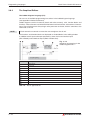
The final program is assembled from the POUs that you define as programs. This process is
handled by the task management, in the Task Pool. Program POUs are put together in groups
referred to as Tasks.
POU-Pool
Task 1
POU 1
Program
POU 1
POU 2
Function
POU 3
POU 3
Program
POU 4
Fig. 2-2:
The program POUs are grouped
together in tasks.
POU 4
Program
POU 5
Function block
Task 2
POU 6
Program
POU 6
POU 7
Program
POU 7
POU 8
Function
Main PLC program
Task 2
Task n
POU 1
POU 6
POU n-1
Instructions
Functions
Function blocks
Instructions
Functions
Function blocks
Instructions
Functions
Function blocks
Task 1
POU 3
POU 7
POU n
Instructions
Functions
Function blocks
Instructions
Functions
Function blocks
Instructions
Functions
Function blocks
Fig. 2-3:
In turn, all the tasks
are grouped together
to form the actual PLC
program.
POU 4
Instructions
Functions
Function blocks
GX IEC Developer Beginner's Manual
2–3
Introduction to the IEC 61131-3 Standard
Getting to Know GX IEC Developer
The Sequential Function Chart language (SFC) is also an aid for writing structured
PLC programs. It is particularly well suited for programming sequential operations.
Fig. 2-4:
An SFC sequence consists of a series
of steps and transitions
(transition or continuos conditions).
Initial step
Transition
Step
Transition
Step
Transition
Transition
Step
Transition
Programming Languages
The actual PLC program code contained in the program organisation units (POUs) and the
steps and transitions of an SFC sequence can be written in any of the available programming
languages. The language used will depend on the nature and size of the programming task.
쎲 The Text Editors:
Instruction List (IL)
Structured Text (ST)
쎲 The Graphical Editors:
Ladder Diagram (LD)
Function Block Diagram (FBD)
Sequential Function Chart (SFC)
2–4
MITSUBISHI ELECTRIC
Getting to Know GX IEC Developer
Introduction to the IEC 61131-3 Standard
Variables
Before you can actually start writing a PLC program you must first decide what variables you
are going to need in the program module you are working on. Each POU has a list of local variables. These are the variables that can only be used within the POU they are defined and
declared for. The global variables, which can be used by all the POUs in the program, are
declared in a separate list.
Header
Body
Local
variables
of
POU 1
PLC program of POU 1
Header
Body
Local
variables
of
POU 2
PLC program of POU 2
Global
variables
Fig. 2-5:
Global and local variables
GX IEC Developer Beginner's Manual
2–5
Introduction to the IEC 61131-3 Standard
2–6
Getting to Know GX IEC Developer
MITSUBISHI ELECTRIC
Basic Terms Used in IEC 61131-3
Projects
3
Basic Terms Used in IEC 61131-3
3.1
Projects
Every GX IEC Developer project consists of the following elements:
쎲 The Library Pool:
- the programming instructions contained in the standard library
- the programming instructions contained in the manufacturer library
쎲 The PLC parameters
쎲 The tasks in the Task Pool
쎲 The structured data types in the DUT Pool
쎲 The global variables
쎲 The program organisation units in the POU Pool
Fig. 3-1
The program element objects are displayed in the
Project Navigator window.
GX IEC Developer Beginner's Manual
3–1
Program Organisation Units (POUs)
3.2
Basic Terms Used in IEC 61131-3
Program Organisation Units (POUs)
Each program organisation unit consists of
쎲 a header and
쎲 a body.
The variables to be used in the POU are defined (declared) in the header.
Fig. 3-2:
POU header (top) and POU body (bottom)
The body contains the actual PLC program.
POUs are divided into three classes on the basis of their functionality:
쎲 Programs [PRG],
쎲 Functions [FUN] and
쎲 Function blocks [FB]
3–2
MITSUBISHI ELECTRIC
Basic Terms Used in IEC 61131-3
3.3
Programs, Function Blocks and Functions
Programs, Function Blocks and Functions
Program
Function block
Function
Programming
instructions
Programming
instructions
Programming
instructions
Function
blocks
Function
blocks
Functions
Functions
Functions
Fig. 3-3:
Programs, function
blocks, and functions
The program POU is the standard program organisation unit. Program POUs can contain programming instructions from libraries, functions and function blocks. The execution of the program POUs is controlled by tasks.
POUs declared as functions or function blocks are independent program elements.
They function effectively as programming instructions that can be replaced whenever necessary, and they can also be used in other program modules, just like ordinary instructions.
NOTES
Function blocks can be called by program POUs and other existing function blocks, but not
from functions. The function blocks themselves can contain programming instructions from
the libraries, functions and other existing function blocks.
Function blocks pass one or more output variables as their result. All the values of the output
variables and the internal values within the function block are stored for the following
execution of the function block. These values are then used the next time the function block
is invoked. This means that invoking the same function block twice with the same input
parameters does not necessarily result in the same output values!
Functions can be called by program POUs, function blocks and other existing functions.
Functions can contain programming instructions from the libraries and other existing
functions.
Functions always pass an output value, and they do not store any internal status information.
Thus, you should always get the same output value every time you invoke a function with the
same input parameters.
Item
Function Block
Function
Internal variable storage
Storage
No storage
Instancing
Required
Not required
Outputs
No output
One output
Multiple Outputs
One output
Repeated execution with same
input values
Does not always deliver the same
output value
Always delivers the same output
value
Tab. 3-1:
Differences: Function Blocks and functions
GX IEC Developer Beginner's Manual
3–3
Parameters and Instancing
3.4
Basic Terms Used in IEC 61131-3
Parameters and Instancing
Functions and function blocks have formal parameters and actual parameters. Formal
parameters are the variables used when a function or function block is created. The formal
parameters of the programming instructions in the standard and manufacturer libraries are not
visible to the user. Actual parameters are the variables that are passed to the function or function block instance (copy) when it is used in another POU. Actual parameters can be defined
variables, hardware addresses or constants.
Fig. 3-4:
The program organisation unit POU_9 is a function block
[FB]. The variables "IN" and "OUT" used in this program
module are declared in the header. "IN" and "OUT" are
the formal parameters.
Function blocks can only be called as instances. The process of "instancing", or making a
copy of the function block, is performed in the header of the POU in which the instance is to be
used. In this header the function block is declared as a variable and the resulting instance is
assigned a name. Note that you can declare multiple instances with different names from one
and the same function block within the same POU. The instances are then called in the body of
the POU and the actual parameters are passed to the formal parameters. Each instance can
be used more than once. For details on activating instances of function blocks in the individual
editors please refer to the chapter "Programming Languages".
Fig. 3-5:
3–4
"Reset" ID an instance of function block POU_9.
"IN" and "OUT" are the formal parameters;
"TimerS1" and "ComeIn" are the actual
parameters of the instance.
MITSUBISHI ELECTRIC
Basic Terms Used in IEC 61131-3
3.5
Tasks
Tasks
A task contains one or more program organisation units declared as programs [PRG].
The task controls the processing of these programs by the controller.
Fig. 3-6:
This project consists of two tasks, MAIN_LD and TASK_2.
If a project contains more than one task you can define execution conditions for the
individual tasks:
Fig. 3-7:
Event: Execute, if the variable ID TRUE.
Interval: Execute at defined time intervals
Priority: Execute in a defined priority order
GX IEC Developer Beginner's Manual
3–5
Variables
3.6
Basic Terms Used in IEC 61131-3
Variables
Variables are similar to operands. They contain the values of inputs, outputs or the internal
memory locations of the PLC system.
A distinction is made between two different variable types, on the basis of their "scope" within
the program as a whole:
쎲 Local variables
쎲 Global variables
Local variables: When program elements are declared as Local Variables, GX IEC Developer
automatically uses some of its System Variables as appropriate storage devices within a specific POU. These variables are exclusive to each POU and are not available to any other routine within a project.
Global variables: Global Variables can be regarded as “shared” variables and are the interface to physical PLC devices. They are made available to all POU’s and reference an actual
physical PLC I/O or named internal devices within the PLC. External HMI and SCADA devices
may interface with the user program using Global Variables.
Declaring Variables
Before you can begin with the actual programming, you should declare the variables you are
going to use in the project as a whole (global variables) and in the individual POUs
(local variables).
Each variable declaration has the following elements:
쎲 Class
쎲 Identifier,
쎲 Absolute address (global variables only),
쎲 Data type,
쎲 Initial value (automatically),
쎲 Comment (optional),
쎲 Remark (global variables only).
IEC61131-3 Verses MELSEC Variables
GX IEC Developer supports program creation, using either symbolic declarations (tag
names), or absolute Mitsubishi addresses (X0, M0 etc), assigned to the program elements.
The use of symbolic declarations complies with IEC 61131.3.
If symbolic declarations are used, then the tag names must be cross referenced to real PLC
addresses.
3–6
MITSUBISHI ELECTRIC
Basic Terms Used in IEC 61131-3
Variables
Local Variable List
For a particular POU to access a Global Variable, it must be declared in its Local Variable List
(LVL), in the POU Header.
The LVL can be made up of both Global Variables and Local Variables.
A Local Variable can be thought of as an intermediate result, i.e. if the program performs a five
stage calculation, using three values and ending with one result, traditionally, the programmer
would construct software, which produced several intermediate results, held in data registers
before ending with the final register result.
It is likely that these intermediate results, serve no purpose other than for storage and only the
final result is used elsewhere.
With GX IEC Developer, the intermediate results can be declared, as Local Variables and in
this case, only the original three numbers and the result, declared as Global Variables.
The Global Variable List
The Global Variable List (GVL) provides the interface for all names, which relate to real PLC
addresses, i.e. I/O data registers etc.
The GVL is available and can be read by all POU’s created in the project.
GX IEC Developer Beginner's Manual
3–7
Variables
Basic Terms Used in IEC 61131-3
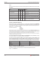
Class
The class keyword assigns the variable a specific property that defines how it is to be used in
the project.
Use in POUs:
Class
Meaning
PRG
FUN
FB
VAR
X
X
X
Variable that is only used within the POU
VAR_CONSTANT
X
X
X
Local variable with unchangeable initial value used
within the POU
VAR_INPUT
—
X
X
Variable passed from outside that cannot be altered
within the POU
VAR_OUTPUT
—
—
X
Variable passed (output) by the POU
VAR_IN_OUT
—
—
X
Local variable passed from outside and passes
(output) by the POU, can be altered within the POU
VAR_GLOBAL
X
—
X
Global variable declared in the Global Variable List
VAR_GLOBAL_CONSTANT
X
—
X
Global variable with unchangeable initial value
declared in the Global Variable List
Tab. 3-2:
Available classes
Identifiers and Absolute Addresses
Each variable is given a symbolic address, i.e. a name. This is referred to as the identifier;
it consists of a string of alphanumeric characters and underline characters. The identifier must
always begin with a letter or an underline character. Spaces and mathematical operator characters (e.g. +, -, *) are not permitted.
Examples of identifiers:
FAULT
ZEROSIG
LIM_SW_5
When global variables are declared they should also be assigned absolute addresses that
reference the memory location of the variable in the CPU or a physical input or output. If you do
not assign the absolute addresses manually, they are assigned automatically.
When local variables are declared in the header of the POU they are automatically assigned a
suitable memory location in the CPU.
You can use either the IEC syntax (IEC-Addr.) or the MITSUBISHI syntax (MIT-Addr.) to assign
the absolute addresses. Two address columns are available.
As soon as you have entered an address in one of these columns, the other address also
appears. You can enter either of the two address formats in both columns. If, for instance, you
enter a MITSUBISHI address in the IEC column, GX IEC Developer identifies it immediately,
places it in the correct column and produces the matching IEC address in the other column.
IEC Address
MITSUBISHI Address
Meaning
%QX0
Y0
Output Y0
%IX31
X1F
Input X1F
%MW0.450
D450
Data register D450
Tab. 3-3:
Examples of absolute addresses
Use upper case letters only and no spaces or mathematical operator characters
(e.g. +, -, *) in addresses.
3–8
MITSUBISHI ELECTRIC
Basic Terms Used in IEC 61131-3
3.7
Data Types
Data Types
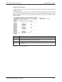
GX IEC Developer supports the following data types.
3.7.1
Simple Types
The data type of a variable defines the number of bits it contains, how they are processed and
the variable's value range. The following data types are available.
Data type
Size
BOOL
Boolean
0 (FALSE), 1 (TRUE)
1 bits
INT
Integer
-32.768 to 32.767
16 bits
DINT
Double integer
-2.147.483.648 to 2.147.483.647
32 bits
WORD
Bit string 16
0 to 65.535
16 bits
DWORD
Bit string 32
0 to 4.294.967.295
32 bits
REAL
Floating-point value
3.4 +/- 38 (7 digits)
32 bits
T#-24d-0h31m23s648.00ms
to
T#24d20h31m23s647.00ms
32 bits
TIME
Time value
STRING
Character string
Tab. 3-4:
NOTE
Value range
max. 50 characters
Available simple data types
Please note that not every data type can be processed by every PLC type!
Initial Value
The initial values are set automatically by the system and cannot be changed by the user.
Comment
You can add a comment up to 64 k characters long for each variable.
Remark
You can add additional user information.
GX IEC Developer Beginner's Manual
3–9
Data Types
3.7.2
Basic Terms Used in IEC 61131-3
Complex Data Types
Arrays
An array is a field or matrix of variables of a particular type.
For example, an ARRAY [0..2] OF INT is a one dimensional array of three integer elements
(0,1,2). If the start address of the array is D0, then the array consists of D0, D1 and D2.
Identifier
Address
Type
Length
Motor_Volts
D0
ARRAY
[0...2] OF INT
In software, program elements can use e.g. Motor_Volts[1] and Motor_Volts[2] as declarations, which in this example mean that D1 and D2 are addressed.
Arrays can have up to three dimensions, for example: ARRAY [0...2, 0...4] has three elements
in the first dimension and five in the second.
Arrays can provide a convenient way of ‘indexing’ tag names, i.e. one declaration in the Local
or Global Variable Table can access many elements.
Data Unit Types (DUT)
User defined Data Unit Types (DUT), can be created. This can be useful for programs which
contain common parts, for example; the control of six identical silos. Therefore a data unit type,
called ‘Silo’ can be created, composing patterns of different elements, i.e. INT, BOOL etc.
When completing a global variable list, identifiers of type Silo can be used. This means that the
predefined group called ‘Silo’ can be used with the elements defined as required for each silo,
thus reducing design time and allowing re-use of the DUT.
3 – 10
MITSUBISHI ELECTRIC
Basic Terms Used in IEC 61131-3
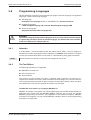
3.8
Programming Languages
Programming Languages
GX IEC Developer supports five programming languages: Two text languages, two graphical
languages, and one structuring language.
쎲 Text language:
Instruction List language IL (IEC IL and MELSEC IL), Structured Text ST
쎲 Graphical languages:
Ladder Diagram language LD, Function Block Diagram language FBD
쎲 Structuring language:
Sequential Function Chart language SFC
E
3.8.1
WARNING:
You cannot change the programming language once you have selected it. Even though
it is physically possible to switch to another language, you will lose the entire contents
of the unit's body if you attempt to do so!
Networks
In all the editors - with the exception of the SFC editor and ST editor - your PLC program is
divided into a number of program sections referred to as networks. Each network is assigned
a name (the network label) which can be used as a destination for jump (goto) instructions.
NOTE
3.8.2
Each network can contain no more than one contiguous circuit unit.
The Text Editors
The following text editors are supported:
쎲 MELSEC Instruction List
쎲 IEC Instruction List
쎲 Structured Text
The structure of all Instruction List types is identical. Each Instruction List consists of a
sequence of controller instructions. Each controller instruction begins on a new line and consists of a programming instruction and its parameters and variables. However, there are significant differences in the way the controller instructions are executed.
The MELSEC Instruction List Language (MELSEC IL)
MELSEC Instruction List programs are written following the rules of DIN 19239 and the programming rules familiar from the MELSEC MEDOC software. You can only use genuine
MELSEC programming instructions (see Appendix of the Reference Manual). MELSEC
Instruction List programs can only contain MELSEC networks. Access to IEC programming
instructions is not possible.
GX IEC Developer Beginner's Manual
3 – 11
Programming Languages
Basic Terms Used in IEC 61131-3
The IEC Instruction List Language (IEC IL)
The IEC Instruction List language allows you to combine IEC networks and MELSEC networks
in a single program.
The IEC networks are programmed according to the IEC 61131-3 rules, and you can use both
IEC programming instructions and the adapted MELSEC instructions (see Appendix in Reference Manual).
�
Fig. 3-8:
Combined Instruction List
networks
�
�
�
쐃
�
Number
Description
�
MELSEC network
�
Network label To enter the network label "NET_01:"
first double-click on the network bar.
�
MELSEC network
�
Network bar
�
Comment text must be enclosed between (* and *) character pairs.
�
The "CJ" instruction performs a jump to the specified destination network.
Tab. 3-5:
Key to figure above
Structured Text (ST)
ST is a text-oriented editor (programming language), similar to PASCAL and supports mathematical functions and a simple creation of loops.
ST body does not contain a network list because it always consists of only one network.
ST is an editor from the IEC 61131 programming standard. The Structured Text editor is compatible to the IEC 61131-3.
All IEC 61131 (IEC 61131-3: PART3-1992) standard functions are supported.
All MELSEC instructions are supported.
Fig. 3-9.
Structured Text body
3 – 12
MITSUBISHI ELECTRIC
Basic Terms Used in IEC 61131-3
Programming Languages
The Accumulator
In the IEC editor the result of each operation is stored in an accumulator directly after execution.
This accumulator always contains the operation result of the last instruction programmed.
NOTE
You do not have to program input conditions (execution conditions) for the operations in this
editor. Execution is always based on the contents of the bit accumulator.
Example
The following illustrates the difference between programming in the MELSEC and IEC editors.
We want to program the addition D0(5)+D1(10) = D2(15) to be executed when input X0 is active.
쐃
쐇
쐋
�
쐂
쐆
Fig. 3-10:
Code for the addition ...
쐏
... in the IEC editor
... in the MELSEC editor
Number
Description
�
The bit accumulator is undefined at the beginning of the network.
�
The accumulator now contains a value of 0 or 1, depending on the state of input X0.
�
The JMPCN instruction (JumpConditionalNot) will be executed if the value in the accumulator is 0.
The instructions in section 쐏 are skipped and the program branches to the "Next:" network.
If the value in the accumulator is 1, JMPCN is ignored and the instructions in 쐏 are executed.
The accumulator then still contains the status of X0, i.e. 1 in this case.
�
Writes the contents of data D0, i.e. 5, to the accumulator.
�
Adds the value in D0 to the value in D1. After the addition the result (15) is stored in the accumulator.
�
Stores the result of the addition to D2. The accumulator still contains the value 15.
Tab. 3-6:
Key to figure above
쑶
GX IEC Developer Beginner's Manual
3 – 13
Programming Languages
Basic Terms Used in IEC 61131-3
Calling Function Blocks
Function blocks can only be called as instances, using the following operators:
CAL
CALC
CALCN
(Call)
(CallConditional))
(CallConditionalNot)
CAL is always executed. CALC and CALCN first poll the status of the bit accumulator; they are
executed only if its value is 1 (CALC) or 0 (CALCN).
The instance name is assigned in the header of the POU. The actual parameters must then be
passed to the formal parameters in the code programmed in the body.
Fig. 3-11:
The formal parameters
of function block
POU_9 are "IN" and
"OUT". Actual
parameters "TimerS1"
and "ComeIn" are
passed to these formal
parameters.
�
�
�
Number
Description
�
Declares the instance "Reset" of function block POU_9.
�
There are two ways to pass actual parameters to formal parameters.
�
There are two ways to pass actual parameters to formal parameters.
Tab. 3-7:
3 – 14
Key to figure above
MITSUBISHI ELECTRIC
Basic Terms Used in IEC 61131-3
Programming Languages
Calling Functions
When you call a function, you must pass the necessary actual parameters to its formal parameters.
A total of n - 1 actual parameters are assigned to every function, where n = total number of
function parameters. This is because the first parameter must always be written to the bit accumulator with the LD instruction.
Example
Fig. 3-12:
Use of "Average", a function written by the user in IEC IL
language. The function has 4 input parameters.
The "Average" function is programmed to perform the following operation:
(D0 + D1 + D2 + D3) : 4.
When the function has been executed the bit accumulator contains the resulting average value
of the four input parameters.
쑶
LD must also be used to pass the first parameter for the EN/ENO functions
(e.g. E_ADD, E_MUL, E_XOR). Their first parameter is always the Boolean EN input
(EN = ENable).
Example
Fig. 3-13:
This writes actual parameter X0 to the EN input. The 3
parameters for execution of the addition are programmed
with the function itself.
The "E_ADD" function performs the following operation: D0 + D1 = D2.
Following execution of this function the bit accumulator will contain the status of the ENO
output (ENO = ENable Out), which in term has the same status as the EN input.
쑶
GX IEC Developer Beginner's Manual
3 – 15
Programming Languages
3.8.3
Basic Terms Used in IEC 61131-3
The Graphical Editors
The Ladder Diagram Language (LD)
You can use all available programming instructions in the ladder diagram language
(see Appendix in Reference Manual).
Ladder diagrams consist of contacts (break and make contacts), coils, function blocks and
functions. These elements are linked with horizontal and vertical lines, referred to as interconnects. These interconnects always begin at the power bar on the left, which is sometimes also
referred to as the rail.
NOTE
Each network can contain no more than one contiguous circuit unit.
The functions and function blocks are displayed as shaded blocks in the editing window.
In addition to their input and output parameters, some also have a Boolean input
(EN = ENable) and a Boolean output (ENO = ENable Out).
쐃 쐇
쐄
쐂
쐆
Fig. 3-14:
Graphical programming in the
ladder diagram editor
쐏
쐋
쐎
쐊
쐅
Number
Description
Network bar
Power bar
Input variable
Output variable
EN input
ENO output
Output variable
Contact
Coil
Comment
Tab. 3-8:
3 – 16
Key to figure above
MITSUBISHI ELECTRIC
Basic Terms Used in IEC 61131-3
Programming Languages
Calling Function Blocks
Function blocks can only be called as instances. The instance name must be declared in the
header of the POU.
In the ladder diagram editor, the name of the function block is displayed inside the shaded
block. The instance name declared in the header must be entered directly above the block.
Then the actual parameters must be passed from outside to the formal parameters shown
inside the block.
Fig. 3-15:
Calling function blocks
쐃
쐇
쐋
쐏
Number
Description
쐃
Declaration of "Reset", an instance of function block POU_9.
쐇
Activation of function block POU_9. The word "Instance" above the shaded block indicates that
you must enter the function block's instance name here.
쐋
The instance name "Reset" has been entered.
쐏
Next, the actual parameters "TimerS1" and "ComeIn" are passed to the formal parameters
"IN" and "OUT".
Tab. 3-9:
Key to figure above
GX IEC Developer Beginner's Manual
3 – 17
Programming Languages
Basic Terms Used in IEC 61131-3
The Function Block Diagram Language (FBD)
In the function block diagram language you can also use all programming instructions (see
Appendix in Reference Manual). They are displayed as shaded blocks which are connected
with the horizontal and vertical interconnect lines. Power bars are not used in this language.
In addition to the normal input and output parameters some blocks also have a Boolean input
(EN = ENable) and a Boolean output (ENO = ENable Out).
쐃
�
쐏
�
쐂
Fig. 3-16:
Graphical programming in the
function block language editor
�
쐆
Number
Description
쐃
Network bar
쐇
Input variable (normal)
쐋
Input variable (negation)
쐏
Function
쐄
EN input
쐂
ENO output
쐆
Output variable
Tab. 3-10: Key to figure above
Calling Function Blocks and Functions
In the function block language, function blocks and functions are called in exactly the same
way as in the ladder diagram language.
3 – 18
MITSUBISHI ELECTRIC
Basic Terms Used in IEC 61131-3
Programming Languages
The Sequential Function Chart Language (SFC)
SFC is a structuring language which allows clear representation of complex processes.
NOTE
The program is the only available program organisation unit (POU) in this language.
The basic elements of the SFC language are steps and transitions.
From 0 to n actions can be assigned to each step. An action can be a Boolean variable (output
or relay) or a PLC program. These programs can be written using any of the editors - including
the Sequential Function Chart language itself. All actions are listed in the Action_Pool in the
Project Navigator window.
Each transition is assigned a transition condition. Transition conditions can be written using
any of the editors - except Sequential Function Chart itself. All transitions are also listed in the
Project Navigator window. Transitions pass control to the next step in the program sequence
when their condition evaluates as logical true.
쐇
쐋
Fig. 3-17:
Sample SFC project
쐃
쐏
쐄
Number
Description
쐃
The "P_Payment" program organisation unit, which is declared as a program [PRG].
쐇
The header contains the POU's variables.
쐋
The PLC program was written with the SFC editor.
쐏
The individual transitions can be written with different editors.
쐄
The Action Pool contains the individual actions, which can also be written in different editors.
Tab. 3-11: Key to figure above
Assignment of actions to steps and of transition conditions to transitions is performed with the
following toolbar icons:
Fig. 3-18:
Activate action/transition condition
Fig. 3-19:
Deactivate action/transition condition
GX IEC Developer Beginner's Manual
3 – 19
Programming Languages
Basic Terms Used in IEC 61131-3
Sequencing Rules
A sequence always begins with an Initial Step, identified by a double outline. The initial step
does not have to be at the physical beginning of the sequence, it can also be placed in other
locations.
Steps are displayed as shaded blocks with names. Transitions are shown as small boxes
placed directly on the vertical connecting lines between the steps.
Only one step can be active at any one time; this also applies in sequences with selective
branching. A step is activated when the directly preceding step is deactivated and the transition condition (i.e. the continue condition) is satisfied. If the continue conditions of two or more
transitions are fulfilled at the same time in a sequence with selective branching, execution priority is defined by the order of the sequences from left to right. This means that only the
sequence that is furthest to the left will be executed. Even if their continue conditions are satisfied, the sequences further to the right will not be executed.
Fig. 3-20:
Graphical programming in the
Sequential Function Chart editor
쐃
�
쐋
쐏
쐇
쐋
쐇
쐋
쐄
�
Number
Description
쐃
Initial step
쐇
Step
쐋
Transition
쐏
Jump exit point
쐄
Jump entry point
쐂
Final step
Tab. 3-12: Key to figure above
Sequences can also contain left and right "divergences" and "convergences" (i.e. alternative
branches for different transition conditions). These branches are identified by a double horizontal interconnect lines.
Jumps are also allowed within sequences. These are effected with exit points (jump instructions) and entry points (labels).
Every step can be declared as a macro step, consisting in turn of a sequence. Macro steps are
identified by two additional horizontal lines within the block. The only limitation on the nesting
depth is the memory capacity of the controller.
NOTE
3 – 20
You will find more detailed information on the sequencing rules of the SFC language in the
Reference Manual.
You can find a detailed example in Chapter 6 of this manual (Step 6).
MITSUBISHI ELECTRIC
Installation
Hardware Requirements
4
Installation
4.1
Hardware Requirements
4.1.1
Recommended Hardware Configuration
쎲 Pentium II 350 processor or above
쎲 64 MB RAM (Microsoft Windows약 2000)
128 MB RAM (Microsoft Windows약 XP)
1024 MB RAM (Microsoft Windows약 Vista)
쎲 Serial interface (RS-232)
쎲 USB port
쎲 Hard disk with at least 200 MB free space
쎲 CD/DVD-ROM drive
쎲 17" (43 cm) VGA monitor (1024 x 768 pixels)
4.1.2
Software Requirements
GX IEC Developer is a 32-bit product. The following operating systems are supported:
쎲 Microsoft Windows약 2000 Professional (with ServicePack 2 or higher)
쎲 Microsoft Windows약 XP Professional (up to ServicePack 3)
쎲 Microsoft Windows약 XP Home Edition (up to ServicePack 3)
쎲 Microsoft Windows약 Vista (32-Bit) (up to ServicePack 1)
Versions of Microsoft Windows which are based on double-byte character sets
(e. g. Japanese) are not supported.
4.2
E
Copyright
WARNING:
This software is protected by copyright. By opening the distribution disks package you
automatically accept the terms and conditions of the License Agreement. You are only
permitted to make one single copy of the original distribution CD-ROM for your own
backup and archiving purposes.
GX IEC Developer Beginner's Manual
4–1
Installing GX IEC Developer
4.3
Installation
Installing GX IEC Developer
During the installation procedure the setup program will create a directory on your hard disk to
copy all the GX IEC Developer files into.
4.3.1
Installing GX IEC Developer on your hard disk
햲 Make sure that the correct Microsoft Windows version is properly installed on your computer.
For information on using Microsoft Windows please refer to the Windows User's Guide.
햳 Start Microsoft Windows.
햴 Insert the installation CD-ROM in the CD-ROM drive.
The GX IEC Developer installation program starts automatically
(if not, execute the file SETUP.EXE on the installation CD-ROM).
햵 Follow the instructions that appear on the screen.
햶 Enter the user name, company name, and serial number of the software.
햷 Follow the instructions that appear on the screen.
햸 When the installation procedure is finished the program will create a new program group in
the Start menu containing the GX IEC Developer program icon.
For further details on the necessary Microsoft Windows procedures please refer to your
Microsoft Windows documentation.
4.3.2
Starting GX IEC Developer
햲 In the Start menu click on the GX IEC Developer program icon. The icon is located in:
Start > Programs > MELSOFT Application > GX IEC Developer. This starts GX IEC Developer and displays the start-up screen.
햳 Confirm with the « key.
4.3.3
Quitting GX IEC Developer
You can quit GX IEC Developer directly at any point in the program by pressing the key combination ¦.
Or:
Click on the Quit command in the Project menu.
4–2
MITSUBISHI ELECTRIC
The User Interface
The Elements of the User Interface
5
The User Interface
5.1
The Elements of the User Interface
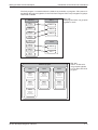
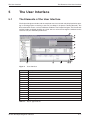
The Project Navigator window and the complete menu bar are both only displayed after opening an existing project or creating a new one (see Step1 in chapter 6 "Getting Started"). The
illustration below shows a variety of different windows: The Project Navigator, PLC Parameter
and the Header and Body windows of a POU. You can resize and arrange the windows on the
screen to suit your individual preferences.
쐃
쐇
쐋
쐏
쐄
쐂
쐆
쐊
쐎
씉
Fig. 5-1:
씈
쐈 쐅
User interface
Item
Description
쐃
Application title bar
쐇
Menu bar
쐋
Toolbar
쐏
Dialogue box
쐄
Button
쐂
Declaration table (header)
쐆
Object window
쐊
Vertical scrollbar
쐎
Editor (body)
쐅
"Maximise" button
쐈
"Minimise" button
쐉
Status bar
씈
Horizontal scrollbar
씉
Project Navigator window
Tab. 5-1:
쐉
Key to figure above
GX IEC Developer Beginner's Manual
5–1
The Elements of the User Interface
5.1.1
The User Interface
The Menu Bar
The GX IEC Developer menu bar uses the standard Windows procedures. When you select
one of the menu titles in the menu bar, a drop-down list of available commands is displayed.
Commands with an arrow symbol open a submenu of additional commands. Selecting a command opens a dialogue or data entry box. The menu structure and the available options are
context-sensitive, changing depending on what you are currently doing in the program.
Options displayed in light grey are not currently available for selection.
NOTE
5.1.2
A list of all menu commands with explanations is provided in the Appendix of the Reference
Manual.
The Toolbar
The toolbar enables you to select the most important menu commands directly by clicking on
the corresponding icons. The toolbar is context-sensitive, i.e. different tool icons are displayed
depending on what you are currently doing in GX IEC Developer.
NOTE
5.1.3
A complete list of all the available tools and icons is provided at the end of the Reference
Manual.
Windows
GX IEC Developer allows you to edit multiple objects at the same time (e.g. body, header, task). A
window is opened on the screen for each object. You can change the size and position of the windows on the screen as you wish. Objects often contain more information than can be displayed in
the window; when this happens, horizontal and vertical scroll bars are included that can be used
to "scroll" the contents of the windows up and down and from side to side.
5.1.4
The Status Bar
The status bar at the bottom of the screen is used to display information on the current status of
your project. You can disable the status bar if you wish, and you can also configure the information to be displayed to suit your needs.
5–2
MITSUBISHI ELECTRIC
The User Interface
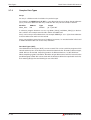
5.1.5
The Elements of the User Interface
The Project Navigator
The Project Navigator is the "control centre" used for selecting and handling the objects used
in GX IEC Developer. This is the starting place for all operations performed on GX IEC Developer objects. The Project Navigator window is not displayed until you open a project. Closing
the Project Navigator window automatically closes the project currently on screen.
Using the Project Navigator
In the Project Navigator tree you can expand a branch by clicking on its [+] symbol and collapse a branch by clicking on its [–] symbol. Expanded and collapsed branches are identified
by different symbols [–] or [+] in the tree. You can also expand or collapse branches by
double-clicking on the appropriate branch icons. Double-clicking on the lowest level opens the
window of the object on that level.
Fig. 5-2:
„Manoeuvring” with the Project Navigator
You can only perform the Cut, Copy, Paste and Delete operations on POU and Task objects. You
can copy and delete multiple objects at the same time. To select individual multiple objects, hold
down the CTRL key and click on the objects one after the other with the left mouse button. To
select a consecutive group of multiple objects, first select the first object with a single click, then
hold down the SHIFT key and click on the last object in the list you want to select.
NOTE
The Extended Information command in the View menu enables or disables the display of
additional information with the items in the Project Navigator window.
Project Navigator views
Three different views can be selected for the Project Navigator via tabs below the Project Navigator window:
Project
This view gives a total overview of the project. It contains all elements of the project.
Calltree
For this view, the corresponding root items are tasks or also POUs, if they are not related to a
specific task. As subitems all used POUs are shown. Additionally, it can be defined per object,
if used global variables should also be shown.
Used by
This view has exactly two root items. The first root item is the POU pool with its POUs as nodes.
Subitems of the POUs and global variables are always POUs calling respectively using the corresponding POU or global variable.
GX IEC Developer Beginner's Manual
5–3
Declaration Tables
5.2
The User Interface
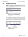
Declaration Tables
The local variables of program organisation units (POU Header) and global variables are
defined in declaration tables.
Fig. 5-3:
Global Variable List
Working with tables
You can access every cell in a table directly by clicking with the mouse. When the insertion
mark (cursor) appears you are in editing mode and can make entries. You can move around in
tables with the following keys and key combinations:
Key
Movement
£
¤
¢
¥
©
ù©
ù«
Line up
Cell right
Line down
Cell left
Step through all cells from left to right
Step through all cells from right to left
Insert new line
You can also add new lines to a table with the New Declaration command from the Edit menu.
You can insert a new line at the beginning, end of the table or before or after the current line.
Deleting Tables and Lines
Clicking on one of the shaded line number boxes at the left selects the corresponding line.
Clicking on the empty uppermost box in the number box column selects the entire table. You
can then delete the selected line or table by pressing the DEL key.
NOTE
The program performs these delete operations immediately, without prompting for
confirmation. If you inadvertently delete something you can recover it by selecting the Undo
command in the Edit menu. Undo only works if you select it directly after the delete
operation, however!
Formatting Tables
You can adjust the width of the table columns to suit your individual needs. Move the mouse
pointer to the dividing line between the shaded column title boxes, so that the pointer changes
to a double-headed arrow. Then press and hold the left mouse button and drag the shaded
dividing line until the column has the desired width.
5–4
MITSUBISHI ELECTRIC
The User Interface
5.3
The Editors
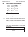
The Editors
Your PLC programs are always divided into a number of logical program sections - referred to
as "networks". These networks can be assigned names (labels) which can then be used as
jump destinations within the PLC program. New networks are inserted with the New Network
command in the Edit menu.
To open an editing window, simply double-click on a Body entry in the Project Navigator window.
Text Editors
쎲 IEC Instruction List
쎲 MELSEC Instruction List
쎲 Structured Text
Graphical Editors
쎲 Ladder Diagram
쎲 Function Block Diagram
쎲 Sequential Function Chart
Please refer to the Reference Manual for full details on using the SFC language.
5.3.1
Using the text editors
All cursor movements and editing functions are similar to those of a standard word processor.
The following additional conventions also apply in the text editors:
쎲 To activate editing mode, click on the surface of a network with the mouse pointer.
쎲 Each program line contains one controller instruction, with the following syntax:
Operator TABSTOP Operand(s)
쎲 The operator and the operands must always be separated by tabstops.
쎲 Pressing F2 when the cursor is in the first column displays a list of available programming
instructions; pressing it in the second column displays a list of available operands
(variables).
쎲 You can also enter optional comments, which can be one or more lines long. Comments
must be enclosed between (* and *) characters.
쎲 You can move around in the program lines with the normal cursor keys.
GX IEC Developer Beginner's Manual
5–5
The Editors
5.3.2
The User Interface
Using the graphical editors
Working in the graphical editors is similar to using a drawing program. You can add elements to
the networks in the editing windows by selecting symbols in the toolbar and with the commands in the Tools menu. The following elements are available:
쎲 Contact (input, LD only)
쎲 Coil (output, LD only)
쎲 Programming instructions
쎲 Input variable
쎲 Output variable
쎲 Return instruction
쎲 Jump label
쎲 Comment
Once you have positioned the elements, you then connect them with one another using interconnect lines.
NOTE
5–6
In Chapter 6 (Step 6) you will learn how to use the different editors
MITSUBISHI ELECTRIC
Getting Started
6
Getting Started
This chapter contains an introductory outline of all the steps required to create a new project
with GX IEC Developer, with clear instructions on the procedures necessary in each step.
Steps
Page
Step 1
Creating New Projects
6-2
Step 2
Creating Tasks
6-4
Step 3
Declaring Global Variables
6-5
Step 4
Creating Program Organisation Units
6-7
Step 5
Programming POU Headers
6-8
Step 6
Programming POU Bodies
6-9
Programming examples:
쎲
Inputs and outputs in LD
Sum function in FBD
쎲 I/O signal configuration parameters
쎲 Timers in LD/FBD/IL
쎲 Sequential Function Chart language
쎲
Step 7
Checking PLC Programs (syntax check)
6-36
Step 8
Configuring Tasks
6-37
Step 9
Compiling Projects
6-39
Step 10
Communications Port Setup
6-40
Step 11
Downloading Programs to the PLC
6-41
Step 12
Monitoring Programs
6-42
Step 13
Uploading Data from the PLC
6-43
GX IEC Developer Beginner's Manual
6–1
Step 1: Creating New Projects
6.1
Getting Started
Step 1: Creating New Projects
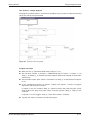
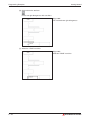
How to create a new project
햲 Select New in the Project menu.
햳 This displays the Select PLC Type dialogue box. Select your PLC in the PLC Type field
and confirm your selection with OK.
Fig. 6-1
CPU type selection
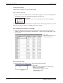
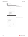
햴 The New Project dialogue box is displayed. Select or enter the path under which you wish to
store the new project.
햵 Enter a name for the new project at the end of the path (the project name is also the name
of the subdirectory/folder in which it is stored). When you are satisfied, click on the Create
button to create the project.
Fig. 6-2:
In this example a project called
PROJ_NEW is being created in the
subdirectory D:\PROJECTS.
Please note that PROJ_NEW is not a
single file, but rather a subdirectory created
by GX IEC Developer to contain all the
project files.
6–2
MITSUBISHI ELECTRIC
Getting Started
Step 1: Creating New Projects
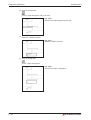
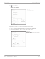
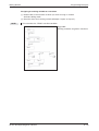
햶 In the dialogue box GX IEC Developer New Project Startup Options click on the Empty
Project option button and confirm with OK.
Fig. 6-3:
GX IEC Developer then creates the empty
new project as defined.
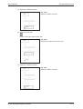
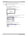
As soon as you have created a new project the Project Navigator window is displayed on the
screen automatically with all the standard entries for the project.
Fig. 6-4:
Project Navigator showing standard
entries for the project and the optionally
activated additional informations
The project entries are displayed in a hierarchical tree structure, which always contains the following standard components:
– Project Name
– Library Pool
– PLC Parameters
– Task Pool
– Data Unit Types Pool
– Global Variables
– Program Organisation Units
Additional information is optionally displayed in brackets behind each entry in the Project Navigator window. You can activate the display of these details by clicking on Extended Information in the View menu (a ✓ check mark is displayed next to the option when it is enabled).
The standard GX IEC Developer window background colour is light grey. You can change all
the colours to suit your personal taste with Colors in the View menu.
GX IEC Developer Beginner's Manual
6–3
Step 2: Creating Tasks
6.2
Getting Started
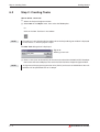
Step 2: Creating Tasks
How to define a new task
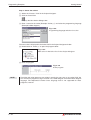
햲 Select the Project Navigator window.
햳 Select New in the Object menu, then select the Task option.
Or
Click on the New Task icon in the toolbar:
NOTE
This tool icon is only displayed in the toolbar when the Project Navigator window is displayed
on the screen, i.e. when a project is open.
The New Task dialogue box is displayed.
Fig. 6-5:
Defining a new task
햴 Enter a name (max. 32 characters) for the new task and confirm with OK. GX IEC Developer
then creates the task and displays the name in the Task Pool in the Project Navigator window.
NOTE
6–4
Assignment of the program organisation units (POUs) to the tasks and definition of the task
attributes will be performed later on in Step 8.
MITSUBISHI ELECTRIC
Getting Started
6.3
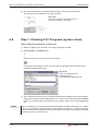
Step 3: Declaring Global Variables
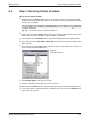
Step 3: Declaring Global Variables
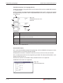
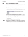
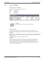
How to declare global variables
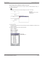
햲 Double-click on the Global_Vars branch in the Project Navigator. This opens the Global
Variable List window on the right hand side of the screen, containing the declaration table
for entry of the variables.
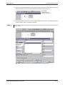
Fig. 6-6:
Declaration table of Global Variable List
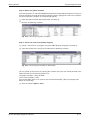
햳 Click in the first cell in the Class column with the mouse cursor, then click on the up arrow
button and select VAR_GLOBAL or VAR_GLOBAL_CONSTANT.
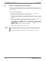
햴 Press © to move to the Identifier column, then enter the identifier for your first global variable.
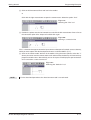
햵 Press © to move to the MIT-Addr. or IEC-Addr. column. Enter the absolute address of the
global variable.
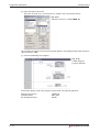
햶 Press © to move to the Type column and click on the up arrow button with the mouse to
open the Type Selection dialogue box.
Fig. 6-7:
Data type selection
햷 Select Simple Types in the Type Class field.
햸 Select the appropriate data type from the list on the left.
The initial value in the Initial column is assigned automatically and cannot be changed by the user.
햹 If you want to enter a comment text for the variable press © to move to the Comment column, then enter your text.
GX IEC Developer Beginner's Manual
6–5
Step 3: Declaring Global Variables
Getting Started
햺 To enter another variable,
– If the editing cursor is active in the Comment column (white background with blinking
cursor), you can create a new variable declaration line by pressing ©.
Fig. 6-8:
Entering another variable
or
– Select any cell in the last line of the table and press ù«.
Fig. 6-9:
Entering another variable
or
– Select New Declaration in the Edit menu and then select the position in which it is to
be inserted from the submenu.
or
– Copy an existing declaration line: First select the line by clicking on its number button at
the left, then press §C to copy it to the clipboard. Then select the insertion position by
clicking on the appropriate number button and press one of the icons
to insert a
new line above or below the selected line. Click on the number of the new line and press
§V to overwrite the new line with the copied line from the clipboard.
햻 Save your new entries with Object - Save.
NOTE
6–6
The terms identifier, address and data type are defined and explained in Chapter 3.
MITSUBISHI ELECTRIC
Getting Started
6.4
Step 4: Creating Program Organisation Units
Step 4: Creating Program Organisation Units
Program organisation units (POUs) always consist of two main parts, a header and a body.
How to create a new program organisation unit
햲 Click on the New POU icon in the toolbar:
NOTE
This tool icon is only displayed in the toolbar when the Project Navigator window is displayed
on the screen, i.e. when a project is open.
햳 Enter a name for the new POU and specify whether it is to be created as a program (PRG),
a function (FUN) or a function block (FB). Then select the programming language/editor to be
used for the creation of the PLC program in the POU's body. When you are satisfied that all
your entries are correct select OK to add the new POU to the project.
Fig. 6-10:
A new POU called "Control" is being defined and
declared as a "Program" (PRG) type.
The PLC program in the body of the POU
is going to be written in ladder diagram language.
The new "Control" POU is then added to the project and appears in the POU Pool in the
Project Navigator window.
Fig. 6-11:
The [+] symbol to the left of "Control" in the project tree
indicates that this entry has subordinate entries that are
currently collapsed. The asterisk in front of the term "Control"
indicates that this POU has not yet been compiled.
햴 Double-click on "Control" to open the subordinate entries.
Fig. 6-12:
Every POU has two main components: a header and a body
containing the actual program in the selected programming
language.
GX IEC Developer Beginner's Manual
6–7
Step 5: Programming POU Headers
6.5
Getting Started
Step 5: Programming POU Headers
The POU header is used to declare and store the variables used by the program that the POU
contains. In addition to global and local variables, these declarations can also include instances
of function blocks.
How to program the POU header
햲 Check that the Header and Body entries are displayed under the POU entry in the
POU Pool and expand them if necessary (see � in Step 4).
햳 Double-click on the "Header" entry in the Project Navigator window. This opens a window
containing the declaration table for the header's local variables on the right hand side of
the screen.
햴 To declare the variables, proceed in exactly the same way as with the global variables in Step
3 above, entering the class, identifier and data type for each variable.
Fig. 6-13: Declaring variables for the program header
햵 Select Save in the Object menu to store your entries
NOTE
If you wish to enter global variables in the header you can copy them from the global
variables declaration table (§C) and then insert them in this declaration table (§v).
The terms class, identifier and data type are defined and explained in Chapter 3.
6–8
MITSUBISHI ELECTRIC
Getting Started
6.6
Step 6: Programming POU Bodies
Step 6: Programming POU Bodies
The body contains the actual code of the PLC program. The programming language used is
shown in the information in brackets following the "Body" entry in the project tree.
How to program the POU body
햲 Check that the Header and Body entries are displayed under the POU entry in the
POU Pool and expand them if necessary (see � in Step 4).
햳 Double-click on the "Body" entry in the Project Navigator. The editing window of the editor
for the selected programming language is opened on the right hand side of the screen.
It contains one network.
Fig. 6-14:
Programming a POU body in a network
editor
If you wish, you can disable the background grid display by clicking on Grid in the View menu
(a ✓ check mark is displayed in the menu when the function is enabled).
You can adjust the size of the background grid with the Environment option in the View menu.
Please note that the value you enter for the grid spacing changes the setting for the entire
screen setup, and not just for the selected programming editor.
햴 Now you can start writing your PLC program.
You will find programming examples for the various programming languages and editors
on the following pages.
햵 Select Save in the Object menu to save the body of your POU.
NOTE
You can increase the size of the editing area with the mouse. Position the mouse pointer on
the lower edge of the network bar box at the left of the editing window (the pointer changes to
a double arrow when it is over the resize line). To resize the editing area, hold down the left
mouse button, drag the dotted line to the desired position and then release the button.
GX IEC Developer Beginner's Manual
6–9
Programming Examples
Getting Started
6.7
Programming Examples
6.7.1
Inputs and outputs in ladder diagram language (LD)
Programming inputs and outputs in the LD editor
햲 In the Project Navigator window, double-click on a program body entry defined with the
ladder diagram language (LD).
햳 Click on the “Contact” tool icon in the toolbar.
Fig. 6-15:
Selecting the "Contact" tool
햴 Move the mouse pointer to the desired position and press the left mouse button to place the
input contact.
Fig. 6-16:
Placing the input contact
햵 Click on the “Coil” tool icon in the toolbar.
Fig. 6-17:
Selecting the "Coil" tool
햶 Move the mouse pointer to the desired position and press the left mouse button to place the
output coil.
Fig. 6-18:
Placing the output coil
6 – 10
MITSUBISHI ELECTRIC
Getting Started
Programming Examples
햷 Click on the"Interconnect/Line" tool icon in the toolbar
or
Click with the right mouse button to open the context menu. Select the option “Line”.
Fig. 6-19:
Selecting the "Line" tool
햸 Position the pointer over the left network bar and click the left mouse button. Draw a line to
the connection point of the output coil and left-click again.
Fig. 6-20:
Drawing a connection line
The "?" character that appears above the input contact and output coil symbols serves as dummy,
which you must replace with declared operand names or a direct address (X, Y).
햹 Click on the "Select mode" tool icon in the toolbar. Using the mouse pointer, select the "?"
dummy character over the contact and the coil and overwrite the dummy character with appropriate variable names. Alternatively, you can also press to display the operand selection list and select a name from the list.
Fig. 6-21:
Selecting the "Selection" tool
NOTE
For the described procedures the Auto Connect mode is not activated.
GX IEC Developer Beginner's Manual
6 – 11
Programming Examples
6.7.2
Getting Started
A Sum Function in FBD Language
Programming a sum function in the FBD editor
Steps 햲 through 햷 below are exactly the same in the ladder diagram and function block diagram editors. Only the tools displayed in the toolbar are different in each case.
햲 In the Project Navigator window, double-click on a body entry defined with the function
block diagram language (FBD).
햳 Click on the “Function Block” tool icon in the toolbar.
Fig. 6-22:
Selecting the
"Function Block" tool
햴 Double-click on the ADD instruction in the selection box displayed.
Fig. 6-23:
Selecting the "ADD" instruction
햵 Position the mouse pointer and press the left mouse button to place the function block.
Fig. 6-24:
Placing the function block
6 – 12
MITSUBISHI ELECTRIC
Getting Started
Programming Examples
햶 Click on the dummy character “?” of the input variable. Overwrite the first dummy character
with the number 12 and the second dummy character with the number 8.
Fig. 6-25:
Overwriting the
dummy character "?"
햷 Click on the dummy character “?” of the output variable and then press to display the operand list. Select "Sum" and confirm with OK.
NOTE
The variables will only appear in the operand list if the header in which they are declared has
been saved.
Fig. 6-26: Declared variables in the header must have been saved
GX IEC Developer Beginner's Manual
6 – 13
Programming Examples
6.7.3
Getting Started
I/O Signal Configuration Parameters
Setting the signal configuration parameters of inputs and outputs
햲 Double-click on an input contact, an output coil or the connection point of a variable in
a function block to display the Signal Configuration dialogue box. Select the appropriate options, then confirm with OK.
Fig. 6-27:
Signal configuration
쐃
�
�
�
�
Number
Description
쐃
Negated input contact (LD only)
쐇
Negated output coil (LD only)
쐋
Set output coil (LD only)
쐏
Reset output coil (LD only)
쐄
Negated input variable (LD and FBD)
쐂
Negated output variable (LD and FBD)
Tab. 6-1:
6 – 14
�
Key to figure above
MITSUBISHI ELECTRIC
Getting Started
6.7.4
Programming Examples
Timers in LD/FBD/IL
Description of the timer device
All timers must have the following four elements:
TValue:
TN:
TC:
TS:
Set point value
Actual value
Output coil
Input contact
Fig. 6-28: The elements TN, TC and TS must be declared in the global variables list.
Fig. 6-29:
The element TValue is passed to the function directly.
The timer example
The following example shows how to program a timer and a function block instance
(see Chapter 3) in ladder diagram, function block diagram and Instruction List languages.
Objective
When "Input1" is set the 100-ms timer "Timer1" must start to count and continue until it
reaches a value of 100. We want "Output1" to be set when "Input2" is set, and we want
"Output1" to be
reset again when the set point value of 100 is reached.
Algorithm:
"Input2" and the timer contact "Timer1S" (TS) are responsible for switching "Output1".
This function will be performed by the user-programmed function block SET_RST."
"Input1" activates the timer, i.e. it controls the switching of the timer coil "Timer1C" (TC).
The set point value TValue is 100. The timer function will be implemented by using the
manufacturer function TIMER_M.
GX IEC Developer Beginner's Manual
6 – 15
Programming Examples
Getting Started
Creating the program
Step 1: Program the function block SET_RST
햲 Create a POU called "SET_RST" and define it as a function block to be programmed
in ladder diagram language (see Step 4).
햳 Enter the following three variables in the header: SET, RST and Q.
햴 Insert two network circuit blocks in the body.
Fig. 6-30: SET and RST are input variables (VAR_INPUT).
Q is an output variable (VAR_OUTPUT).
Q is set when SET is active, and Q is reset when RST is set.
You can configure the S (set) and R (reset) parameters by double-clicking on the coil symbol.
햵 Save the header and the body (Object - Save).
햶 Select the "SET_RST" POU in the Project Navigator window and press ¦«. The following
dialogue box is then displayed:
Fig. 6-31:
Function information
햷 Activate the EN/ENO Contacts check box to assign an EN input and an ENO output to the
function block and activate the Macrocode to create an optimized code.
6 – 16
MITSUBISHI ELECTRIC
Getting Started
Programming Examples
Step 2: Define the global variables
The timer elements TC, TS and TN must first be declared in the Global Variable List. They can
then be called in the header of the POU in which the timer is going to be used. In this example,
the input and output variables are also declared globally.
햲 Open the global variable declaration table (see Step 3).
햳 Declare the following variables.
Fig. 6-32: Declaring the global variables
Step 3: Create the Timer POU (ladder diagram)
햲 Create a new POU as a program using the ladder diagram language (see Step 4).
햳 Open the header of the new POU and declare the following variables:
Fig. 6-33: Declaring the variables in the header
You can speed up this process by copying the variables that you have already entered in the
Global Variable List and inserting them here.
Use global variables = VAR_GLOBAL
Use as local variables = VAR
The variable SET_RST1 is an instance of the function block SET_RST (see Chapter 3 for
details on instancing).
햴 Save the header (Object - Save).
GX IEC Developer Beginner's Manual
6 – 17
Programming Examples
Getting Started
햵 Open the body of the POU.
The timer we shall use is a function that is stored in the manufacturer library.
Fig. 6-34:
The timer function is called TIMER_M
You can find instructions on how to insert function blocks in the editing window in the section on
”Sum Function in FBD”.
햶 Create the following PLC program:
Fig. 6-35:
Ladder Diagram
program example
SET_RST1
The function blocks used in the program can be found in the following libraries:
Manufacturer Library:
Function blocks:
IEC Standard Library:
6 – 18
TIMER_M
SET_RST
MOVE
MITSUBISHI ELECTRIC
Getting Started
Programming Examples
"Input1"
"Timer1C"
10
Timer runs for
10 seconds
0
"Timer1S"
"Input2"
"Output1"
Fig. 6-36: Timer sequence
Timer sequence
The timer sequence begins when INPUT1 is set and the timer starts to run. If INPUT2 is set,
OUTPUT1 is switched on.
When the 10-second period has elapsed, timer contact TIMER1S is set and OUTPUT1 is
switched off again.
If Input2 still remains set or is set, Output1 will be set again.
The lower program block containing the MOVE instruction is only necessary to make it possible to follow the 10-second sequence in monitoring mode.
Programming the timer in function block diagram language
The following illustration shows how to realize the same program using function block diagram
language:
Fig. 6-37:
Function Block Diagram
program example
GX IEC Developer Beginner's Manual
6 – 19
Programming Examples
Getting Started
Function block diagram language
Timer:
Coil:
Contact:
Actual value:
TIMER2C
TIMER2S
TIMER2N
Programming the timer in Instruction List language
The following illustration shows how to realize the same program using Instruction List language:
Fig. 6-38: Instruction List program example
Instruction list language
Timer:
Coil:
Contact:
Actual value:
NOTE
6.7.5
TIMER1C
TIMER1S
TIMER1N
Please refer to Chapter 3 for detailed instructions on how to call functions and pass the actual
parameters to the formal parameters of function block instances in the Instruction List language.
Sequential Function Chart Language
You can find a basic introduction to the SFC programming language in Chapter 3 of this manual.
More detailed information is provided in the Reference Manual. The following example is a
step-by-step illustration of the procedures required to create an SFC program using the GX IEC
Developer tools.
6 – 20
MITSUBISHI ELECTRIC
Getting Started
Programming Examples
The "Process" sample program
The program is called "Process" and solves the problem using a variety of selective branching
constructs and the Jump instruction.
Fig. 6-39: The "Process" program
Program execution
쎲 When the PLC is switched to RUN mode "Output1" is set.
쎲 The transition "TRAN_1" performs a TRUE/FALSE poll of "Input1". If "Input1" is set
"Step_1" and "Step_1_a" are both activated. "Output2" blinks and "Output3" is switched on
continuously.
쎲 The transition "Input2" polls "Input2". If the latter is set "Step_2" is executed and "Output4"
is set.
쎲 In the subsequent branches to "Input3", "Input4" and "Input5" a variety of program
sequences then execute in parallel.
If "Input3" is set, this activates "Step_3". "Input5" activates the jump exit point "Jump"
which leads to the jump entry point "Jump" and also activates "Step_3". "Step_3" sets
"Output5".
If "Input4" is set, this triggers "Step_4", which then switches "Output6".
쎲 "Input6" and "Input7" lead to the end of the program.
GX IEC Developer Beginner's Manual
6 – 21
Programming Examples
Getting Started
Creating the program
Perform steps 1 through 8 in the order described.
Step 1: Create the POU
햲 Create a new POU called "Process". Select PRG (program) as the class and Sequential Function Chart as the programming language (see Step 4).
Fig. 6-40:
The new "Process" POU is displayed in the Project Navigator.
In addition to the header and the body, each POU written in SFC language also has an action
pool entry in which the actions assigned to the POU are stored.
Step 2: Declare the variables in the header
햲 Open the header and enter the local variables to be used in the POU (see Step 3).
Global variables do not need to be declared here, as they can be used directly as global variables.
Fig. 6-41:
In this example only local
variables are used.
Step 3: Open the body
햲 Double-click on the "Body" entry in the Project Navigator window.
Fig. 6-42:
When you open the SFC editor the following
elements are displayed:
- The Initial Step (double outline)
- The transition TRUE
- The Final Step
6 – 22
MITSUBISHI ELECTRIC
Getting Started
NOTE
Programming Examples
Steps to which no actions are yet associated are shown filled in white. The fill colour changes
to grey when actions are associated. Your current position in the sequence is indicated by a
"block cursor", displayed as a black rectangle around the elements that can be moved
around at will in the editing window with the mouse or cursor keys. The tool icons activated in
the toolbar change depending on the current position of this cursor; you cannot use all the
tools at all positions in a program.
Step 4: Create the sequence
햲 Select the "TRUE" transition with the block cursor.
Fig. 6-43:
Selecting the "TRUE" transition
햳 Click on the tool icon
Inserts a new step and transition pair.
Fig. 6-44:
Inserted new step and transition pair
햴 Select the step you have just inserted.
Fig. 6-45:
Selected new step
GX IEC Developer Beginner's Manual
6 – 23
Programming Examples
Getting Started
햵 Click on the tool icon
Inserts a right divergence and a new step.
Fig. 6-46:
Inserted new right divergence and step
햶 Select the "TRUE" transition.
Fig. 6-47:
Selected "TRUE" transition
햷 Click on the tool icon
Inserts a right convergence.
Fig. 6-48:
Inserted new right convergence
6 – 24
MITSUBISHI ELECTRIC
Getting Started
Programming Examples
햸 Select the "TRUE" transition.
Fig. 6-49:
Selected "TRUE" transition
햹 Click on the tool icon
Inserts a new step and transition pair.
Fig. 6-50:
Inserted new step and transition pair
햺 Select the "TRUE" transition.
Fig. 6-51:
Selected "TRUE" transition
GX IEC Developer Beginner's Manual
6 – 25
Programming Examples
Getting Started
햻 Click twice on the tool icon
Inserts two right divergences with transitions.
Fig. 6-52:
Two inserted new right divergences
햽 Select the "TRUE" transition.
Fig. 6-53:
Selected "TRUE" transition
6 – 26
MITSUBISHI ELECTRIC
Getting Started
Programming Examples
햾 Click on the tool icon
Inserts a new step and transition pair.
Fig. 6-54:
Inserted new step and transition pair
햿 Click in the empty space next to the step you have just inserted.
Fig. 6-55:
Selection rectangle for location of new
step and transition pair
GX IEC Developer Beginner's Manual
6 – 27
Programming Examples
Getting Started
헀 Click on the tool icon
Inserts a new step and transition pair.
Fig. 6-56:
Inserted new step and transition pair
헁 Click on the final step.
Fig. 6-57:
Selected final step
6 – 28
MITSUBISHI ELECTRIC
Getting Started
Programming Examples
헂 Click on the tool icon
Inserts a right convergence.
Fig. 6-58:
Inserted new right convergence
헃 Click on the left hand step in the bottom row.
Fig. 6-59:
Selected step in the bottom row
GX IEC Developer Beginner's Manual
6 – 29
Programming Examples
Getting Started
헄 Click on the tool icon
Inserts a jump entry point.
Fig. 6-60:
Inserted jump entry point
헅 Click on the empty space below the free transition.
Fig. 6-61:
Selected position for new item
6 – 30
MITSUBISHI ELECTRIC
Getting Started
Programming Examples
헆 Click on the tool icon
Inserts a jump exit point.
Fig. 6-62:
Inserted jump exit point
Step 5: Assign names to the steps and the jump exit/entry labels.
햲 Click on the element you want to assign a name to. Activates editing mode.
햳 Enter the name (Example: "Step_1" through "Step_4" and "Jump").
Fig. 6-63:
Assigned names to the steps and jump
exit/entry labels
GX IEC Developer Beginner's Manual
6 – 31
Programming Examples
Getting Started
Step 6: Assign transition conditions to the transitions
NOTE
You can use transition programs, TRUE/FALSE and Boolean variables (referenced by direct
address or name) as transition conditions.
Assigning and creating a transition program
햲 Click on the transition to which you wish to assign a program.
Activates editing mode.
햳 Enter the program name (Example: "TRAN_1").
Fig. 6-64:
Entered program name
햴 Click on the tool icon
The New Transition dialogue box is displayed, with the program name you just entered.
햵 Select the programming language (Example: ladder diagram).
Fig. 6-65:
Programming language selection for transition
햶 Click on OK.
The body of the transition program is displayed automatically.
햷 Write the transition program.
Fig. 6-66:
Transition program
6 – 32
MITSUBISHI ELECTRIC
Getting Started
Programming Examples
Assigning an existing variable to a transition
햲 Double-click on the transition to which you wish to assign a variable.
Activates editing mode.
햳 Enter the name of an existing variable (Example: "Input2" to "Input7").
NOTE
This overwrites the "TRUE" transition condition.
Fig. 6-67:
Existing variables assigned to transitions
GX IEC Developer Beginner's Manual
6 – 33
Programming Examples
Getting Started
Step 7: Create the actions
햲 Select the "Process" POU in the Project Navigator.
햳 Click on the tool icon
Displays the New Action dialogue box.
햴 Enter a name for the action (Example: "Action_1") and select the programming language
(Example: ladder diagram).
Fig. 6-68:
Programming language selection for action
The new action is displayed in the Action Pool in the Project Navigator window.
햵 Double-click on "Action_1" to open the program editor.
Fig. 6-69:
New action in the Action Pool in the Project Navigator
햶 Enter the program.
Fig. 6-70:
Action program
NOTE
6 – 34
Transition and action programs are written in exactly the same way as any other POU. You
can write these programs using Instruction List, ladder diagram or function block diagram
language. The Sequential Function Chart language itself is not supported for these
programs, however.
MITSUBISHI ELECTRIC
Getting Started
Programming Examples
Step 8: Assign actions or Boolean variables to the steps
햲 Select the step to which you wish to assign an action or variable (Example: "Step_1").
햳 Click on the tool icon
This displays the Action Association dialogue box, which is still empty.
Fig. 6-71:
Opened Action Association
dialogue box
햴 Press the key.
This displays the Action Name List box showing the actions and Boolean variables that are
currently available.
햵 Select the appropriate action/variable (Example:
"Initial" = "Output1"
"Step_1" = "Action_1"
"Step_1_a" = "Output3"
"Step_2" = "Output4"
"Step_3" = "Output5"
"Step_4" = "Output6"
Fig. 6-72:
Action Name List
GX IEC Developer Beginner's Manual
6 – 35
Step 7: Checking PLC Programs (syntax check)
Getting Started
햶 Close the Action Name List box by double-clicking on the control menu button.
The step will now be displayed with a grey fill colour.
Fig. 6-73:
Fill colour indicates assigned actions or
Boolean variables to the steps
6.8
Step 7: Checking PLC Programs (syntax check)
How to check your program for syntax errors
햲 Select the object to be checked in the Project Navigator window.
햳 Select Check in the Object menu
or
Click on the Syntax Check tool icon in the toolbar:
If the syntax check program finds any errors they are displayed and explained in the
Compile/Check Messages box.
Fig. 6-74:
Errors are displayed and
explained in the
Compile/Check Messages box
햴 You can display the source of any errors found automatically: Double-click on the corresponding error message in the Errors/Warnings list, or select the message and click on the Show
button. This calls the object containing the error, with the source of the error highlighted in
red.
NOTE
6 – 36
You can perform syntax checks both on individual objects and the entire project as a whole.
You can also perform separate checks on the header and body of a single POU. Simply
select the object to be checked in the Project Navigator (to check the entire project select the
Project entry at the top of the tree).
MITSUBISHI ELECTRIC
Getting Started
6.9
Step 8: Configuring Tasks
Step 8: Configuring Tasks
In this section it is assumed that you have already created the tasks for your project
(see Step2). Their entries are displayed in the Task Pool in the Project Navigator tree. Before
you can use them in the program you must first specify the POUs you want to use in the tasks
and configure the task attributes.
How to assign PRG type POUs to tasks
햲 Double-click on the task's entry in the Task Pool. A table is displayed on the right of the
screen in which you can then assemble the task by specifying the POUs it is to contain.
Fig. 6-75:
The task configuration table
햳 Click on the pop-up list icon in the first table line and select the POU you want to add to the
task in the dialogue box displayed. Confirm your selection with OK. Only POUs defined as
programs (PRG) are included in the dialogue box list. The name of the selected POU will
then appear in the POU Name column in the first line of the table.
NOTE
Only POUs that have not yet been included in a previously stored task are included in the
dialogue box list.
Using the © key, move the cursor to the next cell of the table and enter a comment for the POU
entry in the Comment column (optional).
Repeat step 2 for each additional POU you wish to use in the task. To insert a new table line for
the next POU entry, select New Declaration in the Edit menu, then select the position at which
the line is to be inserted in the submenu.
When the cursor is on a comment cell that is currently in edit mode (white background) you can
insert a new line at the end of the table automatically by pressing ©.
GX IEC Developer Beginner's Manual
6 – 37
Step 8: Configuring Tasks
Getting Started
How to configure the task execution attributes
햲 Select the task to be configured in the Project Navigator window or in the task configuration table (select the grey number button in the first table column).
햳 Press ¦« to open the Task Information dialogue box.
The parameters in this dialogue box set the execution conditions and the security level for the
current task. Tasks can be either event-triggered or interval-triggered. Full details on the various execution options can be found in the Reference Manual.
Fig. 6-76:
Event = TRUE
(execute always)
Interval = 0
(because event-triggered)
Priority = 0
(maximum priority)
Priority = 31
(lowest priority)
The dialogue box also shows the current size of the task and the date and time of the last editing change.
NOTE
6 – 38
Please refer to the Reference Manual for details on configuration of the read/write access
parameters.
MITSUBISHI ELECTRIC
Getting Started
6.10
Step 9: Compiling Projects
Step 9: Compiling Projects
When you compile a project the system translates the program code into executable form to
prepare it for downloading to the controller CPU.
How to compile a project
햲 Select Rebuild all in the Project menu.
The progress of the compilation process and any errors found are documented in a status
window.
Fig. 6-77:
Errors are displayed and
explained in the
Compile/Check Messages
box
E
WARNING:
Compilation does not download the program code to the CPU, this must be done
separately!
Always perform a syntax check on the entire project before attempting to compile it
(Step 7).
GX IEC Developer Beginner's Manual
6 – 39
Step 10: Communications Port Setup
6.11
Getting Started
Step 10: Communications Port Setup
Before you can download a project to the PLC you must first configure the communications
port you are going to use for this purpose.
NOTE
Before you begin, make sure that you know precisely which physical interface on your
personal computer is going to be used for transferring the data to the PLC system.
How to select and configure the communications port
햲 In the Online menu select Transfer Setup, then select Ports.
The Connection Setup dialogue box appears.
Fig. 6-78: Interface selection in the Connection Setup
햳 Under PLC side I/F click on the button Seriell/USB.
Fig. 6-79:
PC side I/F
Serial setting
햴 Select either USB or RS-232C. The COM-ports COM1–COM10 can be selected.
햵 Confirm the entries in the dialogue boxes with OK.
6 – 40
MITSUBISHI ELECTRIC
Getting Started
6.12
Step 11: Downloading Programs (to PLC)
Step 11: Downloading Programs (to PLC)
When your program project is complete and has been checked for errors and successfully
compiled you can download it to the controller system for execution.
Connecting the PLC system
햲 Connect the PLC to your personal computer.
햳 Make sure that you plug the connection cable into the same port on the computer that you
defined in the settings described in Step 10 above.
NOTE
Please refer to the Reference Manual for details on the various different options available for
connecting the PC and PLC systems.
How to download a program to the PLC
햲 Select Transfer Setup in the Online menu, then select Project.
The Download Setup dialogue box is displayed on the screen.
Fig. 6-80:
The Transfer Setup dialogue box options are used to
specify which data are downloaded to the PLC.
햳 Click on PLC Parameter and Program, then confirm with OK.
E
WARNING:
You must always download the PLC parameter when you transfer a program to the PLC
for the first time! Q/QnA series PLCs must be formatted first.
햴 Select Transfer in the Project menu, then select Download to PLC to start the download.
The transfer process is documented in a list box; if no error messages are displayed the
transfer has been completed successfully.
GX IEC Developer Beginner's Manual
6 – 41
Step 12: Monitoring Programs
6.13
Getting Started
Step 12: Monitoring Programs
In monitoring mode, GX IEC Developer can display the current status and changes of the variables/devices used by your program.
NOTE
You can only monitor error-free programs that have been compiled and downloaded to the
PLC system for execution.
햲 Select Monitoring Mode in the Online menu. A check mark ✓ in front of the option in
the menu indicates that the mode is currently active, and the entries in the Project Navigator window switch to light grey.
햳 Open the body of the POU that you wish to monitor.
햴 Select Start Monitoring in the Online menu.
NOTE
The PLC must be in RUN mode for monitoring to be possible.
The following examples illustrate how the status changes of the variables are displayed in
monitoring mode for the various programming languages supported by GX IEC Developer.
NOTE
More detailed information on the display options and other monitoring mode features can be
found in the Reference Manual (Chapter 8).
Fig. 6-81:
Function block diagram
Filled rectangle: Binary ON
Rectangle: Binary OFF
DATA = 40: 40 seconds have elapsed
Fig. 6-82:
Ladder diagram
Filled field between the input contacts:
ON
Filled rectangle: Binary ON
Rectangle: Binary OFF
DATA =100: 100 seconds have elapsed
Fig. 6-83:
Instruction list
ON/OFF status is
indicated by filled /not
filled
rectangles.
6 – 42
MITSUBISHI ELECTRIC
Getting Started
6.14
Step 13: Uploading Data from the CPU
Step 13: Uploading Data from the CPU
How to upload data from the PLC's CPU to GX IEC Developer
햲 Select Transfer in the Project menu, then select the Upload from PLC option.
햳 This displays the PLC Parameter dialogue box. Select the appropriate CPU Type and confirm with OK (see Step 1).
햴 In the next dialogue box GX IEC Developer asks you to specify the path and name for the
uploaded project data, which will be stored as a new project.
If you want to create a new project for the upload follow the instructions in Step 1.
If a project is already open you can abort the procedure by clicking on the Cancel button.
햵 Click on Setup in the Transfer Setup dialogue box.
햶 This displays the Transfer Setup (CPU port) dialogue box. Select the correct port for your
system configuration (see Step 10).
햷 Confirm your entries in both dialogue boxes with OK.
This starts the upload procedure. Progress and any errors are documented in a list box.
GX IEC Developer Beginner's Manual
6 – 43
Step 13: Uploading Data from the CPU
6 – 44
Getting Started
MITSUBISHI ELECTRIC
Sample Program: CarPark
7
Project Structure
Sample Program: CarPark
NOTE
This sample program is only intended as an illustration of programming and program
structure techniques in GX IEC Developer. In its present version it cannot be used as a basis
for producing your own executable programs. The sample version has been written for a
MELSEC FX series controller.
Description
The roll-up door of a car park building can be opened from inside and outside with a key-operated switch. Safety functions included in the program ensure that the door opens automatically
in the event of an alarm, and that it does not remain open for too long when no cars are entering
or leaving the car park. The program also keeps track of the number of cars in the building.
7.1
Project Structure
Fig. 7-1:
Project structure
TRUE
Task:
MAIN
Task:
Door_Operate
CPark_OK
POU:
Counter
7.1.1
POU:
Control
POU:
Door_
Control
The Task "Main"
... always runs in the background, with maximum priority. This task contains the POUs "Control" and "Counter", which perform the following functions:
POU "Control"
– Car park status check
– Close car park door if no car drives in or out within a 60-second period
– Open car park door when an alarm is triggered
POU "Counter"
– Count the cars
GX IEC Developer Beginner's Manual
7–1
Create the new "CarPark" project (Step 1 in Chapter 6)
7.1.2
Sample Program: CarPark
The Task "Door_Operate"
... is event-triggered. It is activated when the OK signal for the car park door (variable:
CPark_OK) is set. This task contains the POU "Door_Control", which handles the following
functions:
POU "Door_Control"
– Open car park door when the key switches inside and outside the car park are operated.
– Open car park door when an alarm is triggered
NOTES
GX IEC Developer allows you to apply an engineering design approach to project planning
and programming. This is illustrated in the "CarPark" project. Steps S1 through S11 are fully
documented.
In the sample program all the variables are already known and declared at the outset.
Of course, this ideal situation is not always possible in actual projects; one often has to make
corrections and add and delete variables in the course of the programming work. This
flexible approach is fully supported in GX IEC Developer; the system allows you to edit, add
and delete variable declarations at any time, both during programming and afterwards.
7.2
Create the new "CarPark" project
(Step 1 in Chapter 6)
The first step is to create a new project. Refer to the instructions in S1 and enter "CarPark" as
the project name in step 햵.
7.3
Create the tasks (Step 2 in Chapter 6)
Create the "Main" and "Door_Operate" tasks.
7–2
MITSUBISHI ELECTRIC
Sample Program: CarPark
7.4
Declare the global variables (Step 3 in Chapter 6)
Declare the global variables (Step 3 in Chapter 6)
Declare the global variables shown in the table below. The entries in the Comment column are
optional.
Fig. 7-2:
7.5
Global Variable List
Create the program organisation units
(Step 4 in Chapter 6)
Create the three program organisation units: "Control", "Counter" and "Door_Control". Define all
three POUs as programs (PRG) and specify ladder diagram (LD) as the programming language.
Each POU consists of a header and a body. The header contains the declarations of the variables used by the POU, the body contains the actual PLC program code.
7.5.1
Project Navigator Window
All the tasks and POUs you create are automatically displayed in the Project Navigator window.
Fig. 7-3
Tasks:
"Door_Operate"
"Main"
POUs:
"Control"
"Counter"
"Door_Control"
GX IEC Developer Beginner's Manual
7–3
Program the bodies (Step 6 in Chapter 6)
Sample Program: CarPark
7.6
Program the bodies (Step 6 in Chapter 6)
7.6.1
Body of the "Control" POU
Fig. 7-4:
Door control
activation
Help call and
CO2-alarm
Timer activation
Time control
Close car park
door
Reset
Door control activation
When the main switch is on and no help call or CO2 alarm is registered the OK signal (variable:
"CPark_OK") for the "Door_Control" program organisation unit is set and the
CPark_OK_Lamp is switched on.
Help call and CO2 alarm
As soon as an alarm is registered the motor rolls the car park door up. The motor is reset when
the door activates the upper limit switch ("Door_Open").
Timer activation
When the door is open and the photoelectric barriers at the entrance ("Enter_Car_Gone") and
the exit ("Exit_Car_Gone") do not register any vehicles the timer "Max_Time_Up_C" starts to
count for 60 seconds.
7–4
MITSUBISHI ELECTRIC
Sample Program: CarPark
Program the bodies (Step 6 in Chapter 6)
Time control
The "Time_Control" relay is set as soon as the 60-second period has elapsed.
Close car park door
When no traffic is registered or the main switch is turned off and no alarm is registered the
motor rolls the car park door down into the closed position.
Reset
When no traffic is registered or the main switch is turned off and the door reaches the lower
limit switch ("Door_Closed") both the motor and the "Time_Control" relay are reset.
7.6.2
Body of the "Counter" POU
Fig. 7-5:
Entrance
Exit
Entrance
The program counts the cars driving into the car park by incrementing the total number stored
in the "Cars_Number" data register every time a car enters.
Exit
Every time a car drives out of the building the program decrements the number stored in the
data register. The result is that the number always corresponds to the exact number of cars in
the building.
GX IEC Developer Beginner's Manual
7–5
Program the bodies (Step 6 in Chapter 6)
7.6.3
Sample Program: CarPark
Body of the "Door_Control" POU
Conditions for activation of the door control routine
The Door_Control POU can only be executed when the "CPark_OK" variable in the Control
POU is set. "CPark_OK" is only set if
– The main switch is on, and
– No help call alarm is registered, and
– No CO2 alarm is registered.
Fig. 7-6
Open car park
door
Reset
Close car park
door
Reset
Open car park door
When the car park door is closed the key switch inside ("Exit_Up") or outside ("Enter_Up") the
building must be operated to open the door.
Reset
The motor is reset when the car park door reaches the upper limit switch ("Door_Open").
Close car park door
When a car passes through the photoelectric barrier after driving in ("Enter_Car_Gone") or out
("Exit_Car_Gone") of the building the motor starts to close the car park door.
Reset
When the door reaches the lower limit switch ("Door_Closed") the motor is reset.
7–6
MITSUBISHI ELECTRIC
Sample Program: CarPark
7.7
Configure the tasks (Step 8 in Chapter 6)
Configure the tasks (Step 8 in Chapter 6)
We have already created the two tasks needed by the program, "Main" and "Door_Operate"
(see Step 2).
The next step is to assign the POUs to the tasks, which are still "empty". Double-click on the
task name in the Project Navigator, then select the pop-up arrow icon in the cell in the POU
Name column, and select the POU from the list displayed.
After assigning the POUs you must then configure the task attributes. Select the task in the
Project Navigator window or open the task configuration table by double-clicking on its name,
then press ¦«or select Information in the Object menu to open the Task Information dialogue box.
7.7.1
The "Main" task
Fig. 7-7:
Assign the POUs "Control" and
"Counter" to the "Main" task.
Fig. 7-8:
Attributes of the "Main" task
Event: TRUE
... i.e. the task's two POUs "Control" and
"Counter" both run continuously.
Priority: 1
GX IEC Developer Beginner's Manual
7–7
Configure the tasks (Step 8 in Chapter 6)
7.7.2
Sample Program: CarPark
The "Door_Operate" Task
Fig. 7-9:
The "Door_Operate" task contains the
POU "Door_Control".
Fig. 7-10:
Attributes of the "Door_Operate" task
Event: "CPark_OK"
... i.e. the associated POU Door_Control is only
activated when the "CPark_OK" signal is set.
Priority: 31
NOTE
Entry of the project data is now complete.
햲 Compile the project (Step 9),
햳 configure the ports of your personal computer (Step 10) and
햴 download the program to the controller CPU (Step 11).
햵 Monitoring mode for following the status of the program variables is explained in Step 12.
7–8
MITSUBISHI ELECTRIC
Importing
8
Importing
There are two different ways to import projects created with the older MELSEC MEDOC programming package for use in GX IEC Developer:
쎲 Import by loading a MELSEC MEDOC print file
쎲 Import by uploading directly from the CPU
Loading a print file to GX IEC Developer
Procedures in MELSEC MEDOC
햲 Select a file name as the printer port. The extension TMP is added automatically by the
program.
햳 Make sure that only Instruction List and Name List are selected in the program listing
options. The Header must be switched off!
햴 Start the print procedure.
Procedures in GX IEC Developer
햵 Open the body of an existing MELSEC Instruction List program or create a new POU and
specify MELSEC Instruction List as the language. Important: Make very sure that the
POU is declared as a program (PRG).
햶 In a network click on the left field reading MELSEC.
햷 Open the POU body, then select Import MEDOC Network in the Tools menu.
햸 This opens a file selection box. Select the drive and directory, and then select the print file
(TMP) that you want to load and confirm your choice with OK. This opens another dialogue
box.
햹 Confirm the settings with OK
(MEDOC Program = Instruction List only,
MEDOC Symbolic Names = Name list only).
햺 If necessary, edit the system variables.
NOTES
The structure of MELSEC MEDOC programs can only be remained, if you select MELSEC
mode in the Wizard before!
For further details refer to the Reference Manual
GX IEC Developer Beginner's Manual
8–1
Importing
8–2
MITSUBISHI ELECTRIC
Index
Index
Function · · · · · · · · · · · · · · · · · · · · · · · 3-3
Calling in FBD · · · · · · · · · · · · · · · · · 3-18
A
Calling in text editor · · · · · · · · · · · · · 3-15
POU · · · · · · · · · · · · · · · · · · · · · · · 3-2
Function block · · · · · · · · · · · · · · · · · · · 3-3
Absolute address · · · · · · · · · · · · · · · · · 3-6
Action · · · · · · · · · · · · · · · · · · · · · · · 3-19
Creating · · · · · · · · · · · · · · · · · · · · 6-34
Actual parameter· · · · · · · · · · · · · · · · · · 3-4
Arrays
Overview · · · · · · · · · · · · · · · · · · · · 3-10
B
Calling in FBD · · · · · · · · · · · · · · · · · 3-18
Calling in graph. editor · · · · · · · · · · · · 3-17
Calling in text editor · · · · · · · · · · · · · 3-14
POU · · · · · · · · · · · · · · · · · · · · · · · 3-2
Function Block Diagram · · · · · · · · · · · · · 3-18
Editor· · · · · · · · · · · · · · · · · · · · · · · 5-5
Introduction · · · · · · · · · · · · · · · · · · · 2-4
Programming languages · · · · · · · · · · 3-11
Sample function· · · · · · · · · · · · · · · · 6-12
Bit accumulator · · · · · · · · · · · · · · · · · · 3-13
Body · · · · · · · · · · · · · · · · · · · · · · · · · 3-2
Programming · · · · · · · · · · · · · · · · · · 6-9
C
Colors · · · · · · · · · · · · · · · · · · · · · · · · 6-3
Comment · · · · · · · · · · · · · · · · · · · · · · 3-9
Communications port · · · · · · · · · · · · · · 6-40
D
Data type · · · · · · · · · · · · · · · · · · · · · · 3-9
Data types · · · · · · · · · · · · · · · · · · · · · 3-9
Data Unit Types· · · · · · · · · · · · · · · · · · 3-10
Declaration table · · · · · · · · · · · · · · · · · · 5-4
DUT · · · · · · · · · · · · · · · · · · · · · · · · 3-10
DUT Pool · · · · · · · · · · · · · · · · · · · · · · 3-1
G
Global variable · · · · · · · · · · · · · · · · · · · 3-6
Declaring · · · · · · · · · · · · · · · · · · · · 6-5
Introduction · · · · · · · · · · · · · · · · · · · 2-5
Project · · · · · · · · · · · · · · · · · · · · · · 3-1
Global Variables
List · · · · · · · · · · · · · · · · · · · · · · · · 3-7
Graphical editor· · · · · · · · · · · · · · · · · · 3-16
Introduction · · · · · · · · · · · · · · · · · · · 2-4
GVL
Siehe Global Variable List
H
Hardware requirements ·
Header· · · · · · · · · · ·
Programming · · · · ·
Help · · · · · · · · · · · ·
·
·
·
·
·
·
·
·
·
·
·
·
·
·
·
·
·
·
·
·
·
·
·
·
·
·
·
·
·
·
·
·
·
·
·
·
·
·
·
·
·
·
·
·
·
·
·
·
·
·
·
·
4-1
3-2
6-8
1-2
E
Editor · · · · · · · · · · · · · · · · · · · · · · · · 5-5
Extended information · · · · · · · · · · · · · · · 6-3
F
Final step · · · · · · · · · · · · · · · · · · · · · 6-22
Formal parameter · · · · · · · · · · · · · · · · · 3-4
GX IEC Developer Beginner's Manual
I
Identifier · · · · · · · · · · · · · · · · · · · · · · · 3-8
Declaring · · · · · · · · · · · · · · · · · · · · 3-6
IEC address· · · · · · · · · · · · · · · · · · · · · 3-8
IEC Instruction List
Editing · · · · · · · · · · · · · · · · · · · · · · 5-5
Introduction · · · · · · · · · · · · · · · · · · 3-11
I
Index
Initial step
P
Programming · · · · · · · · · · · · · · · · · 6-22
Sequencing rules · · · · · · · · · · · · · · · 3-20
Parameter· · · · · · · · · · · · · · · · · · · · · · 3-4
Initial value · · · · · · · · · · · · · · · · · · · · · 3-6
PLC configuration · · · · · · · · · · · · · · · · · 3-1
POU Pool · · · · · · · · · · · · · · · · · · · · · · 3-1
Initial Value · · · · · · · · · · · · · · · · · · · · · 3-9
Installation · · · · · · · · · · · · · · · · · · · · · 4-1
Instance · · · · · · · · · · · · · · · · · · · · · · · 3-4
Program · · · · · · · · · · · · · · · · · · · · · · · 3-3
Introduction · · · · · · · · · · · · · · · · · · · 2-2
POU · · · · · · · · · · · · · · · · · · · · · · · 3-2
Instancing · · · · · · · · · · · · · · · · · · · · · · 3-4
Instruction List · · · · · · · · · · · · · · · · · · 3-11
Program Organisation Unit · · · · · · · · · · · · 3-2
Introduction · · · · · · · · · · · · · · · · · · · 2-4
Creating · · · · · · · · · · · · · · · · · · · · · 6-7
Introduction · · · · · · · · · · · · · · · · · · · 2-2
Programming language · · · · · · · · · · · · · 3-11
J
Project · · · · · · · · · · · · · · · · · · · · · · · · 6-2
Project Navigator· · · · · · · · · · · · · · · · · · 6-3
Jump entry point · · · · · · · · · · · · · · · · · 3-20
Jump exit point · · · · · · · · · · · · · · · · · · 3-20
Q
L
Ladder Diagram · · · · · · · · · · · · · · · · · 3-16
Editing · · · · · · · · · · · · · · · · · · · · · · 5-5
Quitting GX IEC Developer · · · · · · · · · · · · 4-2
S
Introduction · · · · · · · · · · · · · · · · · · · 2-4
Programming example · · · · · · · · · · · · 6-10
Programming languages · · · · · · · · · · 3-11
Sequential Function Chart · · · · · · · · · · · 3-19
Editing · · · · · · · · · · · · · · · · · · · · · · 5-5
Local variable· · · · · · · · · · · · · · · · · · · · 3-6
Introduction · · · · · · · · · · · · · · · · · · · 2-5
Local Variables
Introduction · · · · · · · · · · · · · · · · · · · 2-4
Programming example · · · · · · · · · · · · 6-20
Programming languages · · · · · · · · · · 3-11
List · · · · · · · · · · · · · · · · · · · · · · · · 3-7
LVL
Siehe Local Variable List
Signal configuration · · · · · · · · · · · · · · · 6-14
Standard library · · · · · · · · · · · · · · · · · · 3-1
Starting GX IEC Developer · · · · · · · · · · · · 4-2
Status bar · · · · · · · · · · · · · · · · · · · · · · 5-2
Step · · · · · · · · · · · · · · · · · · · · · · · · 3-19
Structured programming · · · · · · · · · · · · · 2-2
Structured Text · · · · · · · · · · · · · · · · · · · 5-5
Editing · · · · · · · · · · · · · · · · · · · · · 3-11
Introduction · · · · · · · · · · · · · · · · · · · 2-4
Programming languages · · · · · · · · · · 3-11
Syntax check · · · · · · · · · · · · · · · · · · · 6-36
M
Macro step· · · · · · · · · · · · · · · · · · · · · 3-20
Manufacturer library · · · · · · · · · · · · · · · · 3-1
MELSEC Instruction List
Editing · · · · · · · · · · · · · · · · · · · · · · 5-5
Programming languages · · · · · · · · · · 3-11
Menu bar · · · · · · · · · · · · · · · · · · · · · · 5-2
MITSUBISHI address · · · · · · · · · · · · · · · 3-8
N
Navigator · · · · · · · · · · · · · · · · · · · · · · 5-3
II
MITSUBISHI ELECTRIC
Index
T
Task
Configuring · · · · · · · · · · · · · · · · · · 6-37
Creating · · · · · · · · · · · · · · · · · · · · · 6-4
Introduction · · · · · · · · · · · · · · · · · · · 2-3
Task Pool · · · · · · · · · · · · · · · · · · · · · · 3-1
Text editor
Introduction · · · · · · · · · · · · · · · · · · · 2-4
Structured Text · · · · · · · · · · · · · · · · 3-12
User interface · · · · · · · · · · · · · · · · · · 5-5
Timer · · · · · · · · · · · · · · · · · · · · · · · · 6-15
Toolbar · · · · · · · · · · · · · · · · · · · · · · · 5-2
Transition · · · · · · · · · · · · · · · · · · · · · 3-19
Transition condition · · · · · · · · · · · · · · · 3-19
Assigning · · · · · · · · · · · · · · · · · · · 6-32
U
User interface · · · · · · · · · · · · · · · · · · · 5-1
V
Variables
Siehe auch Global Variables
Siehe auch Local Variables
W
Wizard · · · · · · · · · · · · · · · · · · · · · · · · 6-3
GX IEC Developer Beginner's Manual
III
Index
IV
MITSUBISHI ELECTRIC