1
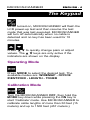
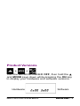
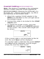
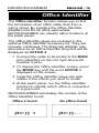
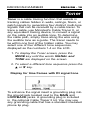
TM MICROSCANNER MICROSCANNER PRO TM User Guide ENGLISH MICROSCANNER ENGLISH - 1 MICROSCANNER ENGLISH - 2 Test Equipment Depot 99 Washington Street Melrose, MA 02176-6024 www.testequipmentdepot.com 800-517-8431 781-665-0780 FAX Table of Contents The Keypad .......................................................... 4 Operating Mode .................................................... 4 Calibration Mode .................................................. 4 Setting the NVP percentage ................................. 5 Changing Display from Meters to Feet ................ 6 Battery .................................................................. 6 High Voltage Protection ........................................ 6 Technical Support ................................................. 7 Product Versions .................................................. 7 MICROSCANNER Tests ...................................... 8 Wiremap ........................................................... 8 Patch Cable Wiremap .............................. 10 Length ............................................................ 11 Network Link Indicator (MICROSCANNER PRO) ......................... 12 Pair Length ............................................... 14 Coaxial Cabling (MICROSCANNER PRO) ......................... 15 Office Identifier ............................................... 16 Office Identifier (MICROSCANNER PRO) ......................... 17 Toner .................................................................. 18 Technical Specifications ..................................... 19 MICROSCANNER ENGLISH - 3 MICROSCANNER ENGLISH - 4 The Keypad When turned on, MICROSCANNER will flash the LCD power-up test and then resume the test mode that was last executed. MICROSCANNER will turn off automatically when no cable is detected and no key has been used for 10 minutes. Press ▲ ▼ to quickly change pairs or adjust values. The ▲ ▼ keys are only active if the indicators are shown on the display Operating Mode Press MODE to select the desired test. The available modes are: WIREMAP - OFFICE IDENTIFIER - LENGTH - TONER Calibration Mode + Turn the MICROSCANNER OFF, then hold the MODE key down while pressing the ON key to start 'Calibrate' mode. Use MICROSCANNER to calibrate cable lengths of more than 50 feet (15 meters) and up to 1500 feet (457 meters.) Setting the NVP percentage Once in Calibrate Mode, the default NVP (Nominal Velocity of Propagation) will be displayed followed by the overall cable length. The cable length is measured with the currently stored NVP. NVP is the measure of how fast a signal travels down a cable compared to the speed of light. The result will be represented as a percentage of the speed of light. For an accurate length test, the NVP must be set correctly. If you know a cable's NVP, change the displayed numbers using the ▲▼ keys until the appropriate NVP is displayed. The cable length will automatically adjust to the new NVP. If you know a cable's length, change the shown NVP using the ▲▼ keys until the appropriate length is displayed. The NVP can be adjusted in 1% increments, and the length changes accordingly. Cables used for calibration must be at least 50 feet (15 meters) long. Cable lengths of less than 50 feet will display FAULT. MICROSCANNER ENGLISH - 5 MICROSCANNER ENGLISH - 6 Changing Display from Meters to Feet During Calibration you will be able to switch the displayed length from meters to feet by simply pressing the MODE key. Press the ON/OFF key once the desired cable length or NVP is displayed to terminate 'Calibrate' mode and store the new calibration factor. MICROSCANNER will use it for future length measurements until another calibration is performed. Battery MICROSCANNER requires a 9 Volt Alkaline battery. The Battery icon is displayed on the screen when MICROSCANNER detects a low battery condition. Using MICROSCANNER with a low battery may effect the test accuracy. If MICROSCANNER is stored for more than one month, the battery should be removed. Note: MICROSCANNER will not function properly with a 9 Volt Carbon Battery. High Voltage Protection MICROSCANNER is designed to withstand input voltage conditions that arise from normal telephony applications such as 48 VDC at less than 80 ma or 24 VAC used to power many keysets. Tests cannot be performed when hazard conditions exist on the inputs. Technical Support If you have technical questions, you may contact Microtest Technical Support by phone, fax or email. North America, Latin America, and Asia Pacific: 1-800-NET-FIXR (1-800-638-3497) (U.S. and Canada only) 1-800-419-8991 (FAX) (U.S. and Canada only) 1-602-952-6483 (Voice) 1-602-952-6494 (FAX) Greater Europe, Middle East, and Africa: +44 1 293 456 025, +44 1 293 456 008 (FAX) Before calling Technical Support, please have your Hardware and Software Version numbers available. For new product information: World Wide Web page at http://www.microtest.com Product Versions + + Turn the MICROSCANNER OFF, then hold the ▲ and MODE keys down while pressing the ON key to display your hardware and software versions. Hardware MICROSCANNER Software ENGLISH - 7 MICROSCANNER ENGLISH - 8 MICROSCANNERTM Tests Wiremap The Wiremap function tests twisted-pair cabling for proper wiring. Your cabling configuration is checked for shield continuity, opens, shorts, crossed pairs, split pairs, and reversed pairs. Test Results are displayed as a numeric representation, where the upper line of fixed digits shows the detected wires at the MICROSCANNER jack, and the lower line of digits indicates the actual wiring. This function requires the use of the Wiremap Adapter at the far end. 1. Connect the cable to be tested to the MAIN jack (identified on the unit right above the modular 8 jack). 2. To display the Wiremap screen, press the MODE key until the word WIREMAP appears on the screen. Following are examples where MICROSCANNER did not detect any faults. Full Wiremap with intact shield shown as a ZERO '0' on the right (4 pair, 8 wires) 10BaseT Cable unshielded (2 pair, 4 wires) Token Ring shielded (2 pair, 4 wires) Below are examples of wiring faults. The FAULT indicator will be displayed and the numerical wire indicators will blink. Reversed: Pair 3 - 6 Crossed: Pairs 4 - 5, 3 - 6 Split Pair Note: If a cable is wired correctly, pin-to-pin, but there is a split pair, Wiremap will display SPLIT PAIR. For example a wire from the 1 - 2 pair could be twisted with a wire from the 3 - 6 pair. MICROSCANNER ENGLISH - 9 MICROSCANNER ENGLISH - 10 If the wire does not go to the far end, the numerical indicator for the open will be left blank. The word Open will be displayed. Shorted pairs are indicated with a connecting bracket, and the word Short will be displayed. Open: Pair 4 - 5 Short: Pair 1 - 2 When the wiring fault includes shorted or swapped non-pair pins (e.g. non-pair pins 1 - 3), the wiremap will display dashes for those numerical wire indicators. Patch Cable Wiremap The Wiremap function can also be used to verify patch cables. 1. Simply plug the two ends of a cable into the two modular 8 jacks (MAIN and LOOP BACK) on MICROSCANNER. 2. To display the Wiremap screen, press the MODE key until the word WIREMAP appears on the screen. If there are any miswires, the number of the faulty wire will blink. Length The Length function measures the full length of a twisted pair or coaxial cable. Twisted pair: If you are measuring standard pair length, MICROSCANNER will determine whether the cable is open, shorted, or connected to a hub. 1. Connect the cable to be tested to the MAIN jack (identified on the unit right above the modular 8 jack). 2. To display the length screen, press the MODE key until the word LENGTH appears on the screen. The overall cable length will be shown. No Cable attached 70 feet cable If the far end of a cable is connected to a hub, MICROSCANNER will display HUB and the cable length. The cable is considered connected to a hub when the 3 - 6 pair is terminated and either pair 1 - 2 or 4 - 5 is terminated. Length to Hub MICROSCANNER ENGLISH - 11 MICROSCANNER ENGLISH - 12 Some early model 100TX only network equipment does not generate link pulses and MICROSCANNER will display HUB, the cable length and the word SIGNAL. Network Link Indicator (MICROSCANNER PRO) The Network Link Indicator allows you to find and identify active network 10/100 hubs and confirm to which hub MICROSCANNER is connected. It will blink the hubs status indicator to assist locating a single channel in a busy wiring closet. 1. Connect the cable to be tested to the MAIN jack (identified on the unit right above the modular 8 jack). 2. To display the length screen, press the MODE key until the word LENGTH appears on the screen. MICROSCANNER displays the word Hub followed by the length to the hub. 3. When MICROSCANNER displays Hub and the cable length, press the MODE key to activate the blinking Hub light. The word SIGNAL blinks once every two seconds right below the word Hub. Go to the wiring closet to view a light that blinks once every two seconds at the port to which the cable is connected. MICROSCANNER detects the kind of hub it is connected to: 10, 100, or 10/100 alternately will be displayed right after the word Hub. The number is followed by the letters F and/or H as an indication for the hub's full or half duplex capabilities. Descriptions are as follows: 10 H 10 HF 100 H 100 HF 100 HF4 - 10BASE-T - 10BASE-T full duplex - 100BASE-TX - 100BASE-T full duplex - 100BASE-T full duplex, 100BASE-T4 MICROSCANNER also Identifies workstations. 1. Connect the cable to be tested to the MAIN jack (identified on the unit right above the modular 8 jack). 2. To display the length screen, press the MODE key until the word LENGTH appears on the screen. MICROSCANNER displays the word PC followed by the length to the PC. MICROSCANNER ENGLISH - 13 MICROSCANNER ENGLISH - 14 3. When MICROSCANNER displays PC and the cable length, press the MODE key to activate the blinking Hub light. Pair Length If ▲▼ are displayed, you will be able to show detailed pair information for each standard conductor pair. 1. Press the ▲ key to display Pair 1 - 2 length. 2. Press the ▲ key again to display the other pair combinations. The pair length is not measured if the cable is too long, connected to a hub, or a wiremap adapter is used. Pair 1 - 2 Length Pair 1 - 2 not measurable Coaxial Cabling (MICROSCANNER PRO) Note: This feature is available in the residential version or when using the COAX upgrade kit. MICROSCANNER measures the full length of a 50 and/or 75Ω (Ohms) coaxial cable, e.g. RG-6 and identifies its termination state. 1. Attach the supplied COAX adapter to the MAIN jack (identified on the unit right above the modular 8 jack). 2. Connect the cable to be tested to the COAX adapter jack. 3. To display the length screen, press the MODE key until the word LENGTH appears on the screen. The overall cable length will be shown. If the coaxial cable is not terminated at the far end, the word Open will be displayed. If a shorted cable is detected, the words FAULT and Short will be displayed, and the length where the short has been found. MICROSCANNER ENGLISH - 15 MICROSCANNER ENGLISH - 16 Office Identifier The Office Identifier function allows you to find the termination of an office cable drop from a wiring closet. By inserting the Office Identifier adapters into RJ-45 office wall outlets, MICROSCANNER can identify office locations at the patch panel. The Office Identifier plugs are included in the optional Office Identifier accessory kit. They are uniquely numbered. The Wiremap Adapter may also serve as an Office Identifier plug and will be displayed as OFFICE 4. 1. Connect the cable to be tested to the MAIN jack (identified on the unit right above the modular 8 jack). 2. To display the Office Identifier screen, press the MODE key until the word OFFICE is displayed on the screen. 3. Insert the Office Identifier plugs into wall outlets in the offices you wish to locate. 4. At the patch panel, run the Office Identifier function to identify which office is connected to a given port. MICROSCANNER will display the number of the Office Identifier found. Office 4 found No office found Office Identifier (MICROSCANNER PRO) The Office Identifier function allows you to find the termination of a twisted pair and/or a coax cable drop from a distribution panel. By inserting the Office Identifier adapters into wall outlets, MICROSCANNER can identify office locations at the distribution panel. The Office Identifier plugs are included in the optional Office Identifier accessory kit. They are uniquely numbered and have RJ-45 connectors on one end and COAX connectors on the other end to allow identification of RJ-45 and/or COAX outlets. 1. Attach the coax adapter to the MAIN jack (identified on the unit right above the modular 8 jack). 2. To display the Office Identifier screen, press the MODE key until the word OFFICE is displayed on the screen. 3. Insert the Office Identifier plugs into wall outlets in the offices you wish to locate. 4. At the distribution panel, connect the cable to be tested to the coax adapter and run the Office Identifier function to identify which office is connected to a given port. MICROSCANNER will display the number of the Office Identifier found. Office 1 found MICROSCANNER No office found ENGLISH - 17 MICROSCANNER ENGLISH - 18 Toner Toner is a cable tracing function that assists in tracking cables hidden in walls, ceilings, floors, or patch panels by generating four distinct multi-tone signals that can be received by a cable tracer. To trace a cable, use Microtest's Cable Tracer II, or any equivalent tracing device, to convert a signal on the cable into an audible tone. To determine the cable path, simply trace along the wire using the audible tone as a guide. The tracer needs to be within one foot of the hidden cable. You may select one of four different tone sequences, displayed as the numbers 1-4 on the LCD. 1. To display the Toner screen, press the MODE key until the words SIGNAL and TONE are displayed on the screen. 2. To select a different tone sequence press the ▲ or ▼ key. Display for time frames with #3 signal tone To enhance the signal insert a grounding plug into the ground jack located next to the MAIN and LOOPBACK jacks. A grounding plug is included in the optional Cable Tracer II kit. You may use any grounding cable that has a standard insulated phone tip plug. Technical Specifications Dimensions: MICROSCANNER : 13.97 cm x 8.25 cm x 2.54 cm (5.5" x 3.25" x 1") Wiremap Adapter: 7.62 cm x 3.18 cm x 2.11 cm (3" x 1.25" x .83") Office Identifier: 7.62 cm x 1.60 cm x 1.47 cm (3" x .63" x .58") Coax Adapter: 7.62 cm x 1.60 cm x 1.47 cm (3" x .63" x .58") Ground pin receptacle size: 2.03 mm (.08") Weight: MICROSCANNER : 171.54 g (.38 lbs) Wiremap Adapter/Office Identifier: 9.03 g (.02 lbs) Power Source: 9 V Alkaline battery User Interface: Display: Custom LCD Size: 4.42 cm x 2.15 cm (1.75" x .85") Keypad: Four momentary contact keys Environmental: Operating Temperature:0° to 50°C (32° to 122°F) Storage Temperature:-10° to 55°C (14° to 131°F) Humidity: 10% to 90% non-condensing Applications: Shielded and unshielded twisted pair cable, 75 or 50 ohm coaxial cable, 10 or 10/100 BASE-T Networks MICROSCANNER ENGLISH - 19 MICROSCANNER ENGLISH - 20 Test Interface: Main: Modular 8 connector for length, 10/100 link identification, wiremap, office identifier/room identifier, trace Loopback: Modular 8 connector for patch cable wiremap Calibration: User selectable NVP NVP calculation based on known cable length Minimum length: 15 meters (50 feet) Length: Maximum length: 450 meters (1500 feet) Office Identifier: Maximum length: 150 meters (500 feet)