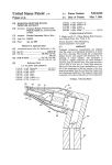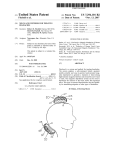
1
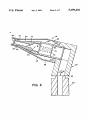
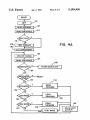
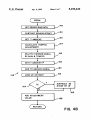
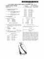
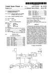
llllllllllllllllllllllllllllllllllllllllllllllllllllllllllllllilllllllllll
US005199436A
United States Patent [191
[11]
[45]
Pompei et a1.
[54] RADIATION DETECTOR HAVING
IMPROVED ACCURACY
[75] Inventors: Francesco Pompei, Wellesley Hills;
Philip R. Gaudet, Jr., Concord, both
[73] Assignee: Exergen Corporation, Newton, Mass.
l/1989
4,831,258
5/ 1989 Paulk et a1. .
4,895,164
5,018,872
l/l990 Wood .
5/ 1991 Suszynski et a1. ................ .. 374/133
0092535 10/1983 Sweden_.
1226540 12/ 1967 United Kingdom .
1425765 3/1973 United Kingdom .
OTHER PUBLICATIONS
Jan. 28, 1991
Houdas et al., Human Body Temperature (Plenum Press:
NY), 83.
Division of Ser. No. 338,968, Apr. 14, 1989, Pat. No.
5,012,813, which is a continuation-in-part of Ser. No.
280,546, Dec. 6, 1988, Pat. No. 4,993,419.
[51]
[52]
[58]
[56]
Int. Cl.5 ....................................... .. A61B 6/00
U.S. Cl. ............................ .. 128/664; 128/736
Field of Search .............. .. 128/664, 736; 374/123,
374/127, 129, 132-133, 135
References (Hted
U.S. PATENT DOCUMENTS
2,658,390 1l/l953
Machler .
3,273,395
Schwartz ............................ .. 73/355
9/1966
3,282,106 11/1966 Barnes .
3,491,596 1/1970 Dean .
3,581,570 6/1971 Wortz .
3,777,568 12/1973 Risgin et al. ........................ .. 73/355
3,878,836
4/1975
Twentier .
-
3,933,045 1/1976 Fox et al. ............................ .. 73/359
3,949,740 4/1976 Twentier .
4,005,605 2/1977 Michael .
4,062,239 12/1977 Fowler etal. .
4,456,390 6/1984 Junkert et a1. .
4,566,808
4,602,642
l/ 1986 Pompei et a1. .
7/ 1986 O’Hara et a1. .
4,614,442 9/1986 Poncy.
4,626,686 12/1986 Pompei et a1. .................... .. 374/128
4,634,294 l/l987 Christol et a1. .
4,636,091 1/1987 Pompei et a1.
4,662,360 5/1987 O’Hara et a1.
4,684,018 8/1987 Jarund .
4,722,612 2/1988 Junkert et a1.
4,784,149 11/1988 Berman et a1.
4,790,324 12/1988 O'Hara et a1.
Fraden .............................. .. 128/736 '
0201790 11/1986 European Pat. Off. .
1914468 11/1970 Fed. Rep. of Germany .
The portion of the term of this patent
subsequent to Feb. 19, 2008 has been
disclaimed.
Related U.S. Application Data
[60]
‘ Apr. 6, 1993
4,797,840
[21] Appl. No.: 646,855
[22] Filed:
5,199,436
FOREIGN PATENT DOCUMENTS
of Mass.
[ 5 ] Notice:
Patent Number:
Date of Patent:
.
.
.
.
.
Det Tronics advertisement, In Tech, Oct. 1987, p. 48.
Dexter Research Center product description for the
Model 1M Thermopile Detector, Oct. 1980.
Proceedings of the Eighth Annual Conference of the
IEEE/ Engineering in Medicine and Biology Society,
Nov. 7-10, 1986, vol. 3 of 3, pp. 1606—l608.
Fraden, Jacob, “Application of Piezo/Pyroelectric
Films in Medical Transducer” Journal of Clinical Engi
neering, Mar/Apr. 1988, pp. 133-138.
Looney, Joseph M. Jr. and Pompei, Francisco, Ear
Thermometry, Reprinted from Medical Electronics,
Jun. 1989.
Primary Examiner-Kyle L. Howell
Assistant Examiner-—John P. Lacyk
Attorney, Agent, or Finn-Hamilton, Brook, Smith &
Reynolds
[57]
7
ABSTRACT
Tympanic temperature measurements are obtained
from the output of a thermopile mounted in an exten
sion from a housing. The housing has a temperature
display thereon and supports the electronics for re
sponding to sensed radiation. The thermopile is
mounted in a highly conductive can which includes a
radiation guide and thermal mass. The guide provides a
narrow ?eld of view due to a fairly high emissivity.
Electronics determine the target temperature as a func
tion of the temperature of the hot junction of the ther
mopile determined from the cold junction temperature
and a thermopile coefficient. The tympanic temperature
is adjusted to provide an indication of core temperature.
5 Claims, 7 Drawing Sheets
U.S. Patent
Apr. 6, 1993
+>
hm: .
uwz
.2
cm
Sheet 3 of 7
5,199,436
US. Patent
Apr. 6, 1993
Sheet 4 of 7
5,199,436
@
INIT
l
n2
READ EEPROM
n4
READ SWITCHES
H6
N
IIB
TEST DISPLAY -
‘2O
.
\—E A/D CONVERSION
,,
I22
I
UPDATE TIMERS
l
I24
READ SWITCHES
/|2e
WEROFF?
Y
POWER DOWNLOOP
I26
N
SWI
CHANGE
Y
RESET
I30
:34
/
N
SCAN
PROCESS
SCAN MODE
I32
N
LOCK
LOCK MODE
I36
N
-\
,
N
PEAK MODE
I40
PROCESS
I38
PEAK
Y
PROCESS
'
TEST MODE
CALCULATE
OUTPUT
I
'42
'44
14s
/
US. Patent
Apr. 6, 1993
Sheet 5 of 7
GET SENSOR RAW DATA
5,199,436
:48
/
SUBTRACT SENSOR OFFSET -/'5o
1
GET T AMBIENT
1'
CALCULATE TEMPCO
ADJUSTMENT
I52
/
_/
MULTIPLY SENSOR S|GNAL
-'56
BY GAIN a TEMPCO
/
GENT AMBIENT)‘
/'58
1
I46
|54
I60
ADD To SENSOR SIGNAL
/
LOOK up 4m ROOT
/'62
I64
SUBTRACT 32
DIVIDE BY L8
J
@
I56
ADD ADJUSTMENT
VALUE
_/|68
FIG. 4B
US. Patent
Apr. 6, 1993
Sheet 6 of 7
5,199,436
UPOATETIMER
COUNTERS
I84
/
SENSOR
CONVERSION
A/D CONVERSION ?
N
I86
THERMISTOR
/
CONVERSION
/
ADJUSTMENT
POT CONV
BATTERY VOLTAGE
CONVERSION
'92
/
SET
I76
IOOMS FLAG /
RESET
UPDATE DISPLAY
_
US. Patent
<
Apr. 6, 1993
BEGIN
Sheet 7 of 7
5,199,436
)
'
I82
TEST BEEPER
‘l
./
TEST DISPLAY
/
'
F‘ 6 40
I84
SEGMENTS
1'
I86
TEST DISPLAY DIGITS
/
READ PUSH BuTToN
_/'88
/
I90
INCREMENT
\
DISPLAY COUNTER
/l92
DISPLAY ADJUSTMENT
4
DoT vALuE
/‘l94
DISPLAY RAW
>__.
SENSOR DATA
/l96
DISPLAY AMBIENT
TEMP
‘
'
/|98
DISPLAY RAW
AMBIENT
DISPLAY BATTERY
voLTS
‘__’
1
5,199,436
2
the unitary thermal mass and which is in close thermal
RADIATION DETECTOR HAVING IIVIPROVED
ACCURACY
contact with the can structure.
It has been found that a narrow ?eld of view radiation
RELATED APPLICATION
This application is a division of application Ser. No.
07/338,968, ?led Apr. 14, 1989, now U.S. Pat. No.
5,012,813, which is a continuation-in-part of application
Ser. No. 07/280,596, ?led Dec. 6, 1988, now US. Pat. 10
No. 4,993,419.
BACKGROUND
Radiation detectors which utilize thermopiles to de
detector provides a more accurate reading of tympanic
temperature. In the detector of the present invention,
that ?eld of view is obtained by controlling the re?ec
tance of the surface of the radiation guide, the length of
the guide and the position of the thermopile behind the
guide. A ?eld of view of less than about sixty degrees
allows for viewing of only a portion of the ear canal
within about 1.5 centimeters of the tympanic mem
brane.
Accuracy of the detector may be improved electroni
tect the heat flux from target surfaces have been used in 15 cally as well. Accordingly, an electronic circuit is cou
pled to a thermopile, having a cold junction and a hot
various applications. An indication of the temperature
junction mounted to view a target, and to a temperature
of a target surface may be provided as a function of the
sensor for sensing the temperature of the cold junction.
The electronic circuit is responsive to the voltage
measured heat ?ux. One such application is the testing
of electrical equipment. Another application has been in
the scanning of cutaneous tissue to locate injured subcu 20 across the thermopile and a temperature sensed by the
temperature sensor to determine the temperature of the
taneous regions. An injury results in increased blood
target. The electronic circuit determines the tempera
flow which in turn results in a higher surface tempera
ture of the target as a function of the temperature of the
ture. Yet another application is that of tympanic tem
hot junction of the thermopile determined from the cold
perature measurement. A tympanic device relies on a
measurement of the temperature of the tympanic mem 25 junction temperature and a known thermopile coeffici
ent. A display provides an indication of the target tem
brane area in the ear of an animal or human by detection
perature determined by the electronic circuit.
As in prior systems, the electronic circuit determines
target
temperature
from
the
relationship
T74=(KH)+T4, where Tris the target temperature, K
of infrared radiation as an alternative to traditional sub
linqual thermometers.
SUMMARY OF THE INVENTION
is a gain factor, H is a sensed voltage from the thermo
An improved tympanic temperature measurement
device is presented in parent US. patent application No.
07/280,546 That device provides for accuracy within
pile and T is a junction temperature of the thermopile.
In accordance with the present invention in a preferred
embodiment, the junction temperature is the tempera
one-tenth of a degree over limited ranges of ambient
temperature and accuracy to within one degree over a 35 ture of the hot junction. The hot junction temperature
T}; is determined from the sensed thermopile voltage
wide range of ambient temperatures. An object of the
and cold junction temperature and a thermopile coef?
present invention is to provide a tympanic temperature
cient. The thermopile coefficient is speci?ed at a prede
measurement device which would provide accuracy to
termined temperature and is temperature compensated
within one-tenth degree over a wide range of ambient
temperatures. In obtaining that accuracy, an object of 40 by the electronic circuit as a function of a temperature
between the hot and cold junctions, speci?cally the
the invention was to continue to avoid any requirement
average temperature. Further, the electronic circuit
for a reference target or for control of the temperature
determines the gain factor K as a function of the differ
of the thermopile as such requirements had resulted in
complexity and difficulties in prior tympanic tempera
ture measurement devices.
ence between a calibration temperature and a tempera
45
A radiation detector comprises a thermopile and a
can enclosing the thermopile. The can structure in
cludes an elongated radiation guide of a ?rst internal
diameter. The radiation guide extends from a viewing
window to a rear volume of larger internal diameter in 50
which the thermopile is mounted. The guide may be
gold plated.
In accordance with one feature of the present inven
tion, the portions of the can forming the radiation guide
and rear volume are formed in a unitary structure of 55
high thermal conductivity material. The can structure
has an outer surface with an outer diameter at its end
adjacent to the window which is less than an outer
diameter about the rear volume. The outer surface is
ture between the hot and cold junction temperatures.
When used to measure a biological temperature, the
radiation detector is further improved by providing an
indication of an internal temperature within biological
tissue. The electronic circuit determines the internal
temperature by adjusting a measured temperature of
surface tissue for ambient temperature. In particular, the
biological surface tissue may be tympanic membrane or
the ear canal adjacent to the membrane, and the display
may provide an indication of core temperature.
BRIEF DESCRIPTION OF THE DRAMNGS
The foregoing and other objects, features and advan
tages of the invention will be apparent from the follow
ing more particular description of preferred embodi
tapered about the radiation guide such that a unitary 60 ments of the invention, as illustrated in the accompany
ing drawings in which like reference characters refer to
thermal mass of increasing outer diameter is provided
the same parts throughout the different views. The
about the end of the radiation guide-adajacent to the
drawings are not necessarily to scale, emphasis instead
rear volume. The unitary can structure maximizes con
being placed upon illustrating the principles of the in
ductance and thermal mass within a limited diameter.
To avoid changes in ?xtures used in mounting the ther 65 vention.
mopile within the can, the unitary can of limited diame
ter may be supplemented with an additional thermal
FIG. 1 illustrates a radiation detector for tympanic
temperature measurements in accordance with the pres
mass which surrounds the rear volume and a portion of
ent invention.
3
5,199,436
FIG. 2 is a cross-sectional view of the extension of the
detector of FIG. 1 in which the thermopile radiation
sensor is positioned.
FIG. 3 is a block diagram of the electronic circuit of
the detector of FIG. 1.
FIGS. 4A-4D are ?ow charts of the system ?rm
ware.
4
expense, the window is square with each side slightly
longer than the diameter of the radiation guide 32. The
window is cemented with epoxy within a counterbore
in a ?ange 37 at the end of the radiation guide. The
epoxy serves as a gas seal and mechanical support for
the somewhat brittle germanium window. The ?ange
serves to protect the germanium window should the
detector be dropped. The diagonal of the window is less
than the diameter of the counterbore, and its thickness is
DESCRIPTION OF A PREFERRED
EMBODIMENT
10 less than the depth of the counterbore. Therefore, if the
detector is dropped, any force which presses the plastic
The radiation detector 12 of FIG. 1 includes a ?at
housing toward the window is absorbed by the ?ange.
housing 14 with a digital display 16 for displaying a
tympanic temperature measurement. Although the dis
play may be located anywhere on the housing, it is
The germanium need only withstand the forces due to
preferred that it be positioned on the end so the user is
not inclined to watch it during a measurement. The
Whereas the detector disclosed in the parent applica
tion had a wide ?eld of view of about 120°, it has been
determined that a signi?cantly narrower ?eld of view of
instrument makes an accurate measurement when ro
tated to scan the ear canal, and the user should concen
trate on only the scanning motion. ‘Then the display can
be read A thermopile radiation sensor is supported
within a probe 18 at the opposite end of the housing 14.
The extension 18 extends orthogonally from an interme
diate extension 20 which extends at an angle of about 15
its own inertia.
about sixty degrees or less provides a more accurate
indication of tympanic temperature. With a narrower
?eld of view, the thermopile ?ake, when directly view
ing the tympanic membrane, also views no more than
about 1.5 centimeters along the ear canal and preferably
less than one centimeter. A better view of the tympanic
membrane also results from the cylindrical extension 43
degrees from the housing 14. As such, the head of the
detector including the extension 18 and 20, has the ap 25 beyond the conical portion of the extension 18. With the
ear canal straightened by the probe, the extension 43
pearance of a conventional otoscope. An on/off switch
can extend well into the ear canal beyond any hair at the
22 is positioned on the housing.
canal opening.
A cross-sectional view of the extension of the detec
The tympanic membrane is about 2.5 centimeters
tor is illustrated in FIG. 2. A base portion 22 is posi
from the opening of the ear canal. The conical portion
tioned within the housing 14, and the housing clamps
of the extension 18 prevents the tip of the extension
about a groove 24. As noted, the portion 20 extends at
from extending more than about eight millimeters into
about a 15 degree angle from the housing and thus from
the ear canal. Beyond that depth, the patient suffers
the base portion 22. The extension 18 is tapered toward
noticeable discomfort. With a ?eld of view of about
its distal end at 26 so that it may be comfortably posi
toned in the ear to view the tympanic membrane and/or 35 sixty degrees, the ear canal which is about eight milli
meters wide is viewed about eight millimeters from the
ear canal.
tip of the extension 18. Thus, only the ear canal within
A preferred disposable element to be used over the
about 1.5 centimeters of the tympanic membrane is
extension 18 is presented in parent US. patent applica
viewed as the radiation guide is directed toward the
tion No. 07/280546 and will not be discussed here.
The edge at the end of the probe is rounded so that 40 membrane. The result is a more accurate reading of the
tympanic temperature which is closer to core tempera
when the probe is inserted into the ear it can be rotated
ture.
somewhat without discomfort to the patient. The probe
With the present instrument, the narrow ?eld of view
is also curved like an otoscope to avoid interference
is obtained by two changes to the ,prior radiation guide.
with the ear. By thus rotating the probe, the ear canal is
scanned and, at some orientation of the probe during 45 The re?ectivity within the guide is reduced. Radiation
entering the tube at greater angles must be re?ected a
that scan, one can be assured that the maximum temper
greater number of times from the radiation guide before
ature is viewed. Since the ear canal cavity leading to the
reaching the thermopile ?ake. With the higher emissiv
tympanic area is the area of highest temperature, the
ity, such radiation is less likely to reach the ?ake to be
instrument is set in a peak detection mode, and the peak
detected during the scan is taken as the tympanic tem 50 detected. The ?eld of view is further decreased by ex
tending the enlarged rear volume between the ?ake and
perature.
the radiation guide. Radiation which enters the radia
An improved assembly within the extension 18 is
illustrated in FIG. 2. A thermopile 28 is positioned
within a can 30 of high conductivity material such as
copper. The conductivity should be greater than two
watts per centimeter per degree Kelvin. The can is
?lled with a gas of low thermal conductivity such as
Xenon. The thermopile 28 is positioned within a rear
volume. 31 It is mounted to an assembly which includes
tion guide at greater angles, yet travels through the
radiation guide, leaves the guide at greater angles and is
thus unlikely to be viewed by the ?ake. The length of
the radiation guide is another parameter which sheets
the ?eld of view. By using a planoconvex lens as the
window 35, the ?eld of view can be further
Both of the above approaches to decreasing the ?eld
a ?ange 33. The volume is sealed by cold welding of the 60 of view increase the amount of heat which is absorbed
by the can in which the thermopile is mounted. The
?ange 33 to a ?ange 41 extending from the can. Cold
welding is the preferred approach to making the seal
added heat load adds to the importance that the can,
including the radiation ‘guide, have a large thermal mass
and high thermal conductivity as discussed below.
The thermopile views the tympanic membrane area 65 As distinguished from the structure presented in the
parent application, the volume 31 surrounding the ther
through a radiation guide 32. The radiation guide 32 is
mopile and the radiation guide are formed of a single
gold plated to minimize oxidation. It is closed at its
piece of high conductivity copper. This unitary con
forward end by a germanium window 35. To minimize
and, to utilize past welding ?xtures, the outer diameter
of the can is limited.
5
5,199,436
6
struction eliminates any thermal barriers between the
thermopile which is rated to temperatures of 125° C. a
foremost end of the radiation guide and the portion of
low temperature solder of indium-tin alloy which ?ows
the can surrounding the thermopile which serves as the
at 100° C. is allowed to flow into the annular mass 34 to
cold junction of the thermopile. Further, at least a por
provide good thermal coupling between all elements.
tion of added thermal mass which surrounds the radia
The thermal resistance from the outer surface of the -
tion guide is unitary with the can as well. Speci?cally, a
taper 39 results in an enlarged region 41 which serves as
a thermal mass in accordance with the principals of the
parent application. The taper 39 continues along a con
plastic sleeve 38 to the conductive thermal mass is high
to minimize thermal perturbations to the inner thermal
mass. To minimize changes in temperature of the guide
conductive plug 36. Both the mass 34 andplug 36 are of
36 should be large. To minimize thermal gradients
copper and are in close thermal contact with the can 30.
The outer sleeve 38 of the extension 18 and the inter
mediate extension 20 are of plastic material of low ther
where there is some temperature change in the tube
during measurement, the thermal resistance between
32 with any heat transfer to the can which does occur,
ductive thermal mass 34 which surrounds the can and a 10 the thermal mass of the can 30, annular mass 34 and plug
mal conductivity. The sleeve 38 is separated from the
can 30 and thermal mass 34 by an insulating air space 40.
any two points of the thermal mass should be low.
Thus, due to the large time constant of the thermal
barrier, any external thermal disturbances, such as when
the extension contacts skin, only reach the conductive
The taper of the can 30 and thermal mass 34 permits the
thermal mass at extremely low levels during a measure
insulating space to the end of the extension while mini
ment period of a few seconds; due to the large thermal
mizing the thermal resistance from the end of the tube
32 to the thermopile, a parameter discussed in detail 20 mass of the material in contact with the cold junction,
any such heat transfer only causes small changes in
below. The inner surface of the plastic sleeve 38 may be
temperature; and due to the good thermal conductance
coated with a good thermal conductor to distribute
throughout the thermal mass, any changes in tempera
across the entire sleeve any heat received from contact
ture are distributed quickly and are reflected in the cold
with the ear. Twenty mils of copper coating would be
25 junction temperature quickly so that they do not affect
suitable.
temperature readings.
In contrast with the prior design, the portion of the
sleeve 38 at the foremost end of extension 18 has a re
The thermal RC time constant for thermal conduc
tion through the thermal barrier to the thermal mass and
gion 43 of constant outer diameter before a tapered
tube should be at least two orders of magnitude greater
region 45. The region of constant outer diameter re
duces the outer diameter at the distal end and minimizes 30 than the thermal RC time constant for the temperature
response of the cold junction to heat transferred to the
interference when rotating the extension in the ear to
tube and thermal mass. The RC time constant for con
view the tympanic membrane area. The tapered region
duction through the thermal barrier is made large by the
is spaced six millimeters from the end of the extension to
large thermal resistance through the thermal barrier and
allow penetration of the extension into the ear canal by
35 by the large thermal capacitance of the thermal mass.
no more than about eight millimeters.
The RC time constant for response of the cold junction
One of the design goals of the device was that it
is made low by the low resistance path to the cold junc
always be in proper calibration without requiring a
tion through the highly conductive copper can and
warm-up time. This precluded the use a heated target in
thermal mass, and the low thermal capacitance of the
a chopper unit or heating of the cold junction of the
stack of beryllium oxide rings and pin conductors to the
thermopile as was suggested in the O’Hara et al. US.
Pat. No. 4,602,642. To accomplish this design goal, it is
necessary that the system be able to operate with the
thermopile at any of a wide range of ambient tempera
tures and that the thermopile output have very low
thermopile.
Although the cold junction capacitance is naturally
low, there are size constraints in optimizing the thermal
capacitance of the thermal mass, the thermal resistance
45 through the thermal barrier and the internal thermal
sensitivity to any thermal perturbations.
resistance. Speci?cally, the external thermal resistance
The output of the thermopile is a function of the
can be increased by increased radial dimensions, the
difference in temperature between its warm junction,
capacitance of the thermal mass can be increased by
heated by radiation, and its cold junction which is in
increasing its size, and the thermal resistance through
hot junction respond only to radiation viewed through 50 the longitudinal thermal path through the tube can be
decreased by increasing its size. On the other hand, the
the window 35, it is important that the radiation guide
close thermal contact with the can 30. In order that the
32 be, throughout a measurement, at the same tempera
ture as the cold junction. To that end, changes in tem
perature in the guide 32 must be held to a minimum, and
any such changes should be distributed rapidly to the
cold junction to avoid any thermal gradients. To mini
size must be limited to permit the extension to be readily
positioned and manipulated within the ear.
Besides the transfer of heat from the environment,
another signi?cant heat flow path to the conductive
thermal
mize heatmass
transfer
is through
throughleads
thattopath,
the the
system.
leadsTo
are kept
mize temperature changes, the tube 32 and the can 30
to
small
diameters.
Further,
they
are
embedded
in the
are, of course, well insulated by means of the volume of
plug 36 through bores 70; thus, any heat brought into
air 40. Further, a high conductance thermal path is
provided to the cold junction. This conductance is en 60 the system through those leads is quickly distributed
throughout the thermal mass, and only small changes in
hanced by the unitary construction. Further, the can 30
temperature and small gradients result.
is in close thermal communication with the thermal
Because the temperature of the thermal mass is not
masses 34 and 36, and the high conductivity and thick
controlled, and the response of the thermopile 28 is a
ness of the thermal masses increase the thermal conduc
tance. A high thermal conductivity epoxy, solder or the 65 function of its cold junction temperature, the cold junc
tion temperature must be monitored. To that end, a
like joins the can and thermal masses. The solder or
thermistor is positioned at the end of a central bore 72 in
epoxy provides a signi?cant reduction in thermal resis
the plug 36.
tance. Where solder is used, to avoid damage to the
7
5,199,436
8
With transistor TI on, the switch 22 can be used as an
A schematic illustration of the electronics in the hous
input through diode D2 to the microprocessor to initi
ate any programmed action of the processor.
In addition to the display, the system has a sound
output 90 which is driven through the driver 84 by the
ing 14, for providing a temperature readout on display
16 in response to the signal from the thermopile, is
presented in FIG. 3. The system is based on a micro
processor 73 which processes software routines in
cluded in read only memory within the processor chip
microprocessor.
The processor may be a 6805 processor sold by Motor
ola.
In order to provide an analog output from the detec
tor, a digital-to-analog convertor 92 is provided. When
selected by line 94, the convertor converts serial data on
The voltage generated across the thermopile 28 due
to a temperature differential between the hot and cold
line 96 to an analog output made available to a user.
junctions is ampli?ed in an operational ampli?er 74. The
Both calibration and characterization data required
for processing by the microprocessor may be stored in
an electrically erasable programmable read only mem
ory (EEPROM) 100. The EEPROM may, for example,
be a 93046 sold by International CMOS Technologies.
analog output from the ampli?er 74 is applied as one
input to a multiplexer 76. Another input to the multi
plexer 76 is a voltage taken from a voltage divider R1,
R2 which is indicative of the potential V+ from the
power supply 78. A third input to the multiplexer 76 is
Inc. The data may be stored in the EEPROM by the
the potential across a thermistor RTl mounted in the
bore 72 of block 36. The thermistor RTl is coupled in a
voltage divider circuit with R3 across a reference po
tential VRef. The ?nal input to the multiplexer is a 20
potential taken from a potentiometer R4 which may be
adjusted by a user. The system may be programmed to
respond to that input in any of a number of ways. In
particular, the potentiometer may be used as a gain
control or as a DC offset control.
microprocessor when the EEPROM is selected by line
102. Once stored in the EEPROM. the data is retained
even after power down. Thus, though electrically pro
grammable, once programmed the EEPROM serves as
a virtually nonvolatile memory.
Prior to shipment, the EEPROM may be pro
grammed through the microprocessor to store calibra~
tion data for calibrating the thermistor and thermopile.
25 Further, characterization data which de?nes the per
sonality of the infrared detector may be stored. For
example, the same electronics hardware, including the
microprocessor 73 and its internal program, may be
the select lines 78. The selected analog signal is applied
used for a tympanic temperature detector in which the
to a multiple slope analog system 80 used by the micro
processor in an integrating analog-to~digital conversion 30 output is accurate in the target temperature range of
about 60° F. to a 110° F. or it may be used as an indus
80. The subsystem 80 may be a TSCSOOA sold by Tele
trial detector in which the target temperature range
dyne. It utilizes the reference voltage VRef from a
would be from about 0° F. to 100° F. Further, different
reference source 82. The microprocessor 73 responds to
modes of operation may be programmed into the sys
the output from the convertor 80 to generate a count
35 tem. For example, several different uses of the sound
indicative of the analog input to the convertor.
At any time during the software routine of the micro
processor 73, one of the four inputs may be selected by
The microprocessor.drives four 7-segment LED dis
source 90 are available.
_
Proper calibration of the detector is readily deter
plays 82 in a multiplexed fashion Individual displays are
mined and the EEPROM is readily programmed by
selected sequentially through a column driver 84, and
means of an optical communication link which includes
within each selected display the seven segments are
a transistor T2 associated with the display. A communi
controlled through segment drivers 86.
cation boot may be placed over the end of the detector
When the switch 22 on the housing is pressed, it
during a calibration/characterization procedure. A
closes the circuit from the battery 78 through resistors
photodiode in the boot generates a digitally encoded
R5 and R6 and diode D1 to ground. The capacitor C1
optical signal which is ?ltered and applied to the detec
is quickly charged and ?eld effect transistor T1 is
turned on. Through transistor T1 the V+ potential 45 tor T2 to provide an input to the microprocessor 73. In
a reverse direction, the microprocessor, may communi
from the storage cell 78 is applied to a voltage regulator
cate optically to a detector in the boot by ?ashing spe
86. The regulator 86 provides the regulated +5 volts to
ci?c segments of the digital display 82. Through that
the system. It also provides a reset signal to the micro
communication link, an outside computer 106 can moni
processor. The reset signal is low until the +5 volt
tor the outputs from the thermistor and thermopile and
reference is available and thus holds the microprocessor
perform a calibration of the devices. A unit to be cali
in a reset state. When the +5 volts is available, the reset
brated is pointed at each of two black body radiation
signal goes high, and the microprocessor begins its pro
sources while the microprocessor 73 converts the sig
grammed routine.
nals and sends the values to the external computer. The
When the switch 22 is released, it opens its circuit, but
a charge is maintained on capacitor C1 to keep transis 55 computer is provided with the actual black body tem
peratures and ambient temperature in the controlled
tor TI on. Thus, the system continues to operate. How
environment of the detector, computes calibration vari
ever, the capacitor C1 and transistor T1 provide a very
simple watchdog circuit. Periodically, the microproces
ables and returns those variable to be stored in the de
tector EEPROM. Similarly, data which characterizes a
particular radiation detector may be communicated to
the microprocessor for storage in the EEPROM.
tor T1 on. If the microprocessor should fail to continue
A switch 108 is positioned behind a hole 110 (FIG. 1)
its programmed routine, it fails to charge the capacitor
in the radiation detector so that it may be actuated by a
C1 within a predetermined time during which the
rigid metal wire or pin. Through that switch, the user
charge on C1 leaks to a level at which transistor T1
turns off. Thus, the microprocessor must continue in its 65 may control some speci?c mode of operation such as
converting the detector from degrees Fahrenheit to
programmed routine or the system shuts down. This
degrees centigrade. That mode of operation may be
prevents spurious readings when the processor is not
stored by the microprocessor 73 in the EEPROM so
operating properly.
sor applies a signal through driver 84 to the capacitor
C1 to recharge the capacitor and thus keep the transis
5,199,436
that the detector continues to operate in a specific mode
until a change is indicated by closing the switch 108.
A switch 106 may be provided either internally or
10
perature of the thermopile. The Seebeck coefficient can
be determined from the relationship
through the housing to the user to set a mode of opera
(4)
tion of the detector. By positioning the switch at either
the lock position, the scan position or a neutral position,
any of three modes may be selected. The first mode is
the normal scan mode where the display is updated
continuously. A second mode is a lock mode where the
display locks after a selectable delay and then remains
frozen until power is cycled or, optionally, the power
tion temperature. Again, it can be seen that temperature
compensation is based on the average thermopile tem
on button is pushed. The sound source may be caused to
perature rather than just the cold junction temperature.
sound at the time of lock. The third mode is the peak
mode where the display reads the maximum value
found since power-on until power is cycled or, option
ally, the power-on button is pushed.
The processor determines when the voltage from the
divider R1, R2 drops below each of two thresholds.
where auis the speci?ed Seebeck coefficient at a partic
ular speci?cation temperature and T5 is that specifica
By substituting equation (4) into equation (3) and solv
ing for T3, the hot junction temperature is found to be
T11=[(Tco'7's+l)i (Tm'Ts+1)2-(2'Tc0)8
[(Tea((Tc'T:)-(T /2))+Tc+(Vs/J'a,,)] 51/7“;
(5)
The actual sensor output Vs can be determined from
enables the sound source to indicate that the battery is 20 the digital value available to the processor from the
equation:
'
low and should be replaced but allows continued read
out from the display. Below the lower threshold, the
KAD
(6)
processor determines that any output would be unreli
Below the higher threshold, the processor periodically
able and no longer displays temperature readings. The
Vs= (fl-1105;;
unit would then shut down upon release of the power 25
where KAD is the analog-to-digital conversion factor in
button.
volts/bit and GP); is the gain of the front end ampli?er.
In the present system, the target temperature is com
Reference to the hot junction temperature rather than
puted from the relationship
the cold junction temperature in each term of the rela
tionship for determining the target temperature pro
TI‘=KII(H—HO)+TH‘
(1)
vides for much greater accuracy over a wide range of
where Tris the target temperature, Kh is a gain calibra
tion factor, H is the radiation sensor signal which is
offset by H0 such that (H—-HO)=O when the target is at
ambient temperatures and/or target temperatures.
To provide a temperature readout, the microproces
sor makes the following computations: First the signal
the cold junction temperature of the device to counter 35 from thermistor RTl is converted to temperature using
any electronic offsets in the system, and T}; is the hot
a linear approximation. Temperature is defined by a set
junction temperature. This relationship differs from that
of linear equations
previously used in that Kh is temperature compensated
relative to the average temperature of the thermopile
rather than the cold junction, or ambient, temperature. 40
where x is an input and no is an input end point of a
Further, the hot junction temperature rather than the
straight line approximation. The values of M, x0 and b
cold junction temperature is referenced in the relation
ship.
are stored in the EEPROM after calibration. Thus, to
The gain calibration factor Kh is temperature com
obtain a temperature reading from the thermistor, the
45 microprocessor determines from the values of no the
pensated by the relationship,
line segment in which the temperature falls and then
performs the computation for y based on the variables
M and b stored in the EEPROM.
— Tz
The hot junction temperature is computed A fourth
power representation of the hot junction temperature is
then obtained by a lookup table in the processor ROM.
The sensed radiation may be corrected using the gain
calibration factor Kh, the sensor gain temperature coef
ficient Toe, the average of the hot and cold junction
at which the instrument was calibrated. The use of the
average temperature of the thermopile rather than the 55 temperatures and a calibration temperature T: stored in
the EEPROM. The corrected radiation signal and the
cold junction temperature provides for a much more
fourth power of the hot junction temperature are
accurate response where a target temperature is signi?
summed, and the fourth root is taken. The fourth root
cantly different from the ambient temperature.
calculation is also based on a linear approximation
As noted, the relationship by which the target tem
perature is determined includes the hot junction temper 60 which is selected according to the temperature range of
interest for a particular unit. Again, the break points and
ature as the second term rather than the cold junction
coefficients for each linear approximation are stored in
temperature. Hot junction temperature is computed
where G is an empirically determined gain in the sys
tem. T00 is the temperature coefficient of the Seebeck
coefficient of the thermopile and T2 is the temperature
from the relationship
V:=J um (TH— Tc)
the EEPROM and are selected as required.
An additional factor based on ambient temperature
(3) 65 may also be included as an adjustment. The temperature
where JN is the number of junctions in the thermopile
and am is the Seebeck coefficient at the average tem
of the ear T, which is sensed by the thermopile is not
actually the core temperature T”. There is thermal
resistance between Tc, and '1}. Further, there is thermal
11
5,199,436
Beep at button push in lock mode
none/20/40/ 80 milliseconds long
Beep at lock
none/20/40/ 80 milliseconds long
Beep at power down
est and the ambient temperature. Based on an assumed
constant Kc which is a measure of the thermal resis
tances between T", Te and Ta, core temperature can be
computed as
none/20/40/80 milliseconds long
Beep at lowbattery
none/20/40/ 80 milliseconds long
T, — Ta
interval l/2/3 sec
kc
single/double beep
This computation can account for a difference of from
one-half to one degree between core temperature and
sensed ear temperature, depending on ambient tempera 15
ture.
A similar compensation can be made in other applica
tions. For example, in differential cutaneous tempera
ture scanning, the signi?cance of a given differential
reading may be ambient temperature dependent.
The actual computations performed by the processor
are as follows, where:
H is the digital value of radiation signal presented to
the processor
H0 is the electronic offset
He is corrected H (deg K“)
12
Sound source functions:
resistance between the sensed ear temperature and the
ambient temperature. The result is a sense temperature
Te which is a function of the core temperature of inter
Timeout functions:
Time to power-down
0.5 to 128 sec in 0.5 sec increments
Delay until lock
0.5 to 128 sec in 0.5 sec increments
Other functions:
Power-on button resets lock cycle
Power-on button resets peak detect
Display degrees C / degrees F
EEPROM “Calibrated” pattern to indicate that the
device has been calibrated
EEPROM checksum for a self~check by the pro
cessor
' FIGS. 4A-4D provide a flowchart of the ?rmware
stored in the microprocessor 73. From reset when the
Tc is ambient and cold junction temperature (deg F)
instrument is turned on, the system is initialized at 110
Taf is 4th power of Tamb (deg K“)
and the contents of the EEPROM are read into memory
Tt is target temperature (deg F)
in the microprocessor at 112. At 114 the processor reads
T2 is ambient temp during cal (deg F)
30 the state of power and mode switches in the system. At
Td is the displayed temperature
116, the system determines whether a mode switch 113
Rt is the thermistor signal
has placed the system in a self-test mode. If not all eights
Kh is a radiation sensor gain cal factor
Zt is a thermistor zero cal factor
are displayed on the four-digit display 82 for a brief time
At 120 the system performs all A-to-D conversions to
Th is the hot junction temperature
35 obtain digital representations of the thermopile output
(13515 the Seebeck coefficient of the thermopile at a’ and the potentiometer settings through multiplexor 76.
speci?ed temperature
The system then enters a loop in which outputs dic
I is the number of junctions in the thermopile
tated by the mode switch are maintained. First the tim
Tco is a temperature coefficient for the Seebeck coef
ticient
Ts is the temperature at which a“ is specified
Tcr is core temperature
kc is a constant for computing core temperature
ers are updated at 122 and the switches are again read at
V5 is the sensor output voltage
GFE is the gain of the front end ampli?er
K4}; is the analog-twdigital conversion factor
panic temperature detector, some detectors have a
Vs=(I-I—Ho)KAD/GFE
Tc(deg F)=Thermistor lookup table (Rt)-Zt
TH: [(Tco'Ts+ l)i[(Tco"Ts+ l)2 - (2'Tco)*
[(T¢O((Tc'T-$)—(Tc2/2))+T<=+(Vs/
124. When the power is switched off, from 126 the
system enters a power down loop at 128 until the system
is fully down. At 130, the mode switch is checked and
if changed the system is reset. Although not in the tym
45 mode switch available to the user so that the mode of
operation can be changed within a loop.
At 132, 136 and 140, the system determines its mode
of operation and enters the appropriate scan process
134, lock process 138 or peak process 142. In a scan
50 process, the system updates the output to the current -
reading in each loop. In a lock process, the system up
dates the output but locks onto an output after some
period of time. In the peak process, the system output is
Thf(deg K4)=4th power lookup table (Tc)
Tt(deg F)=(Hc+Thf)1 (Final lookup table)
the highest indication noted during a scan. In each of
55 these processes, the system may respond to the pro
gramming from the EEPROM to perform any number
Tt(deg C)=(5/9) ' (Tf(deg F)—32) optional
of functions as discussed above. In the peak process
The following is a list of the information which may
which is selected for the tympanic temperature mea
be contained in the EEPROM and therefore be pro
surement, the system locks onto a peak measurement
grammable at the time of calibration:
60 after a preset period of time. During assembly, the sys
Radiation sensor offset
tem may be set at a test mode 144 which will be de
Radiation sensor gain
Radiation sensor temperature coefficient
Thermistor offset
Ambient temperature at calibration
scribed with respect to FIG. 4D.
Thermistor lookup table
Final temperature lookup table
Adjustment factor F
-
In any of ‘the above-mentioned modes an output is
calculated at 146. Then the system loops back to step
65 122. The calculation 146 is illustrated in FIG. 4B.
At 148 in FIG. 4B the raw sensor data is obtained
from memory. The sensor offset taken from the BE
PROM is subtracted at 150 and the ambient temperature
13
5,199,436
14
increment, the battery voltage is displayed. After the
previously obtained from the potentiometer RTl is
accessed at 152. The temperature coefficient adjustment
is calculated at 154. At 156, the sensed signal is multi
plied by the gain from EEPROM and by the tempera
test, the assembler sets the mode switch to the proper
operating mode.
While this invention has been particularly shown and
described with references to preferred embodiments
thereof, it will be understood by those skilled in the art
that various changes in form and details may be made
therein without departing from the spirit and scope of
the invention as de?ned by the appended claims.
ture coefficient. At 158, the fourth power of the ambient
temperature is obtained, and at 160 it is added to the
sensor signal. At 162, the fourth root of the sum is ob
tained through a lookup table. Whether the display is in
degrees centigrade or degrees Fahrenheit is determined
at 164. If in degrees centrigrade, a conversion is per
We claim:
1. A temperature detector comprising:
a housing adapted to be held by hand;
an extension from the housing adapted to be inserted
formed at 166. At 168, adjustment values, including that
from the potentiometer R4, are added.
Analog-to-Digital conversion is performed periodi
cally during an interrupt to the loop of FIG. 4A which
into an ear;
a radiation sensor supported within the detector and
occurs every two milliseconds. The interrupt routine is
illustrated in FIG. 4C. Timer counters are updated at
170. A-to-D conversions are made from 172 only every
which receives radiation passing into the extension
from a target area in the ear;
100 milliseconds when a ?ag has been set in the prior
interrupt cycle. During most interrupts, an A/D con
version does not occur. Then, the IOO-milliseoond 20
counter is checked at 174, and if the count has expired,
a ?ag is set at 176 for the next interrupt. The flag is
checked at 178 and, if found, the display is updated at
180. The system then returns to the main loop of FIG.
a temperature display on the housing for displaying
temperature; and
a battery powered electronics in the housing for con
verting radiation sensed by the sensor to tempera
ture displayed by the display, the electronics in
cluding a processor for providing an inner body
temperature displayed on the housing as a function
25
4A.
Where the 100 millisecond ?ag is noted at 172 an
A-to-D conversion is to be performed. The system ?rst
determines at 182 whether a count indicates there
of the received radiation, indicating target temper
ature, compensated by an indication of ambient
temperature to provide an inner body temperature
approximation.
2. A temperature detector as claimed in claim 1
should be a conversion of the thermopile output at 184
or a conversion of the the thermistor output at 186. The 30 wherein the inner body temperature is core tempera
ture.
thermopile sensor conversion is performed nine out of
ten cycles through the conversion loop. At 188, the
3. A radiation detector comprising:
system checks to determine whether a conversion is
a radiation sensor mounted to view a target of biolog
made from the potentiometer R4 or from the battery
voltage divider R1, R2 at 192. These conversions are
a temperature sensor for sensing ambient tempera
ical surface tissue;
made alternately.
ture;
an electronic circuit coupled to the radiation sensor
and temperature sensor and responsive to a signal
from the radiation sensor and the temperature
sensed by the temperature sensor to provide an
FIG. 4D illustrates the self-test sequence which is
called by the mode switch 113 only during assembly.
During the test, the beeper sounds at 182 and all display
segments are displayed at 184. Then the system steps
each character of the display from zero through nine at
186. The system then enters a test loop. At 188, the
system senses whether the button 108 has been pressed.
indication of an internal temperature adjusted for
the-ambient temperature to which the surface tissue
is exposed; and
an output for providing an indication of the internal
If so, a display counter is incremented at 190. The dis—
temperature.
play for the unit then depends on the count of the dis 45
4. A radiation detector as claimed in claim 3 wherein
play counter. With the zero count, the adjustment po
the output is a display.
tentiometer value is displayed at 192. Thereafter, if the
5. A radiation detector as claimed in claim 3 wherein
display counter is incremented by'pressing the button
the biological surface tissue includes a tympanic mem
108, the raw sensor data is displayed. With the next
increment, ambient temperature is displayed at 196, and 50 brane and the display provides an indication of core
temperature.
with the next increment, the raw output from the ambi
ent temperature sensor RTl is displayed. With the next
55
65
US005 1 9943 6C1
(12) EX PARTE REEXAMINATION CERTIFICATE (586lst)
United States Patent
(10) Number:
US 5,199,436 C1
Pompei et a1.
(54)
(45) Certi?cate Issued:
RADIATION DETECTOR HAVING
IMPROVED ACCURACY
(75) Inventors: Francesco Pompei, Wellesley Hills,
MA (US); Philip R. Gaudet, Jr.,
.
.
.
.
(73) Asslgnee: PNC Bank, National Association,
Pmsburgh, PAWS)
_
_
ReeX3IIllIl3tl0Il Request:
4,907,895 A
4,993,419 A
5,012,813 A
3/1990 Everest
2/1991 Suszynski
5/1991 Pompei et al.
5,199,436 A
4/1993 pqmpel et al'
i
Concord’ MA (Us)
Aug. 21, 2007
30512:“ a1~
5,381,796 A
1/1995 Pompei
5,445,158 A
8/1995
5,653,238 A
8/1997 Pompei
6,047,205 A
4/2000 Pompei
6,292,685 B1
9/2001
2002/0026119 A1
Pompei
Pompei
8/2001 Pompei
NO. 90/007,951, Feb. 24, 2006
FOREIGN PATENT DOCUMENTS
Reexamination Certi?cate for:
Patent No.:
5,199,436
Issued:
Appl. No.:
Apr. 6, 1993
07/646,855
Filed:
Jan. 28, 1991
Related US. Application Data
(60)
EP
EP
JP
JP
JP
W0
W0
W0
Division of application No. 07/338,968, ?led on Apr. 14,
now Pat. No. 4,993,419.
(51)
Int. Cl.
A61B 6/00
A61B 5/00
5/1997
8/2002
1/1980
1/1980
5/1983
6/1990
3/1998
3/2000
OTHER PUBLICATIONS
1989, now Pat. No. 5,012,813, which is a continuation-in
part of application No. 07/280,546, ?led on Dec. 6, 1988,
0 447 455 B1
0 763 349 B1
55-11597
55-011597
58-88627
WO 90/06090
WO 98/08431
WO 00/16051
“A simple but interesting history of Infrared Thermom
eters,” Version 017, WWW.ZyTemp.com.
(2006.01)
(2006.01)
(Continued)
Primary ExamineriBeverly M. Flanagan
(52)
(58)
US. Cl. ...................................... .. 600/474; 600/549
Field of Classi?cation Search ..................... .. None
See application ?le for complete search history.
(56)
References Cited
U.S. PATENT DOCUMENTS
2,710,559
2,984,747
3,374,354
3,781,837
4,302,971
4,317,998
4,854,730
4,895,164
A
A
A
A
A
A
A
A
6/1955
5/1961
3/1968
12/1973
12/1981
3/1982
8/1989
1/1990
Heitmuller et al.
Walker
Hood
Anderson et a1.
Luk
Dore
Fraden
Wood
(57)
ABSTRACT
Tympanic temperature measurements are obtained from the
output of a thermopile mounted in an extension from a
housing. The housing has a temperature display thereon and
supports the electronics for responding to sensed radiation.
The thermopile is mounted in a highly conductive can Which
includes a radiation guide and thermal mass. The guide
provides a narroW ?eld of vieW due to a fairly high emis
sivity. Electronics determine the target temperature as a
function of the temperature of the hot junction of the
thermopile determined from the cold junction temperature
and a thermopile coefficient. The tympanic temperature is
adjusted to provide an indication of core temperature.
US 5,199,436 C1
Page 2
OTHER PUBLICATIONS
“Human Body Temperature: Its Measurement and Regula
tion,” Y. Houdas and BE]. Ring, Penum Press, 1982.
“Infrared Thermocouples,” article appearing at WWW.om
ega.com Website.
Det Tronics advertisement, Intech, p. 48, Oct. 1987.
Exergen Product Speci?cation for “MicroScannerTM E
AutoZero”.
FirstTempTM Intelligent Medical Systems, Operation
“Noncontact Temperature Sensing With Thin Film Thermo
Manual, Model 2000A, pp. li7, Undated.
pile Detectors,” by Condrad Hamel, Sensors, pp. 29*3l
Omega Medical Product Speci?cation for Surface Term
perature Scanner STSilooiF/C & l0l*C, by Omega Medi
cal Product Corporation.
(Jan. 1989).
“Standard Speci?cation for Infrared Thermometers for Inter
mittent Determination of Patient Temperature,” American
Societyfor Testing and Materials, Designation E l965i98,
pp. lil6 (1998).
“The Encyclopedia of Electronics,” Second Printing, edited
Principles and Methods of Termperature Measurement, Tho
mas D. McGee, John Wiley & Sons, Inc., Publishers, pp.
by Charles Susskind, Reinhold Publishing Corporation,
237*239, 25li252, 257*258, 265*266, 296*298, 302,
334i336,373i374,393i395 (1988).
New York, pp. 260, 856*857, 864 (1967).
“The Equine Infrared Thermographic Scanner: Assuring
Corp. and distributed by Dermathorm Corp.
Sketch of Radiation Detector manufactured by IR*ONICS
Performance of the Equine Athlete . . . at the Speed of
Light,” Equine Infrared, by Marybeth Ryan.
“Thermal Sensors Based on the Seebeck Effect,” A. W.
“Thermometry,” James F. Schooley, Ph. D, CRC Press, Boca
Raton, Florida, pp. l48il 5 l, l72il 83.
HerWaarden and PM. Sarro, Sensors and Actuators,
10(1986) pp. 32li346.
“Thermography as an Indicator of Blood Perfusion,” by Tom
I. Love, Annals, NY Academy of Sciences, pp. 429*437
User
(1980).
EHS Infrared Scanner”.
Manual
for
“Surface
Temperature
Scanner
STS*l0(%F/C & 101*c”, Omega Medical Corporation.
Exergen Corporation Product Advertisement for “Exergen
US 5,199,436 C1
1
2
EX PARTE
AS A RESULT OF REEXAMINATION, IT HAS BEEN
REEXAMINATION CERTIFICATE
ISSUED UNDER 35 U.S.C. 307
DETERMINED THATI
The patentability of claims 1*5 is con?rmed.
NO AMENDMENTS HAVE BEEN MADE TO
THE PATENT
*
*
*
*
*