1
H-25C
INDUSTRIAL HALOGEN LEAK DETECTOR
Instruction 3015-0216
Operation & Maintenance
Rev.0
Product Leadership z Training z Service z Reliability
H-25C Instruction Manual
Table of Contents
Introduction ..................................................................................................................................4-9
1.
2.
3.
4.
5.
6.
7.
H-25C Leak Detector Applications....................................................................................................................4
Unpacking and Initial Checks............................................................................................................................4
Warranty............................................................................................................................................................4-5
Procuring and Storing Frequently Replaced Maintenance Items .....................................................................5
Operating Precautions ......................................................................................................................................5-6
Preparing for Use ..............................................................................................................................................7-8
Special Symbols and Formatting Used in this Manual .....................................................................................9
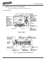
1. Names and Functions of Components..................................................................................10-14
1.1
1.2
1.3
1.4
1.5
1.6
Components Names and Functions .................................................................................................................10-11
Model Codes .....................................................................................................................................................11
Specifications ....................................................................................................................................................12
Probes ...............................................................................................................................................................13
Accessories and Maintenance Tool .................................................................................................................13-14
Internal Flow List ...............................................................................................................................................14
2. Preparing for Use....................................................................................................................15-25
2.1 Installing the Sensor..........................................................................................................................................15
2.2 Setting the Switches..........................................................................................................................................16
2.2.1 Setting the “Supply Voltage” (type of AC voltage used) switch.............................................................16
2.2.2 Setting the “GAS” (Type of Gas) switches ............................................................................................16
2.2.3 Setting the”UNIT” (Unit State Selector) switch ......................................................................................16
2.2.4 Setting the “RELAY” (Relay State Selector) switch...............................................................................17
2.2.5 Setting the “MODE” (Measurement Mode Selector switch ..................................................................18
2.2.6 Setting the Alarm Point ..........................................................................................................................18
2.2.7 Setting the “CAL” (Calibration Mode Selectorl) switch ..........................................................................19
2.2.8 Setting the “CAL INTVL” (Calibration Request Interval) switch.............................................................19
2.2.9 Setting the “GAIN” (Search Mode Sensitivity) .......................................................................................20
2.3 Connecting the Probe .......................................................................................................................................21
2.4 Connecting the Power Cable ............................................................................................................................21
2.5 Applying Power (Turning the Power Switch ON) ..............................................................................................21-22
2.6 Calibration Gas Secondary Pressure Adjustment ............................................................................................23-24
2.7 Calibration .........................................................................................................................................................24
2.8 Adjusting the Speaker Tone Volume ................................................................................................................25
2.9 Allowing Air to Flow at the End of Preparation .................................................................................................25
3. Calibration ...............................................................................................................................26-32
3.1 Auto Calibration.................................................................................................................................................28
3.1.1 Setting the switches...............................................................................................................................28
3.1.2 Operator actions and the calibration operation .....................................................................................28-29
3.1.3 What to do if the “CAL FAIL” indicator appears.....................................................................................30
3.2 Manual Calibration ............................................................................................................................................31
3.2.1 Setting the switches...............................................................................................................................31
3.2.2 Operator actions and calibration operation ...........................................................................................31
3.2.3 What to do if the CAL FAIL appears......................................................................................................31
3.2.4 What to do if the alarm code appears ...................................................................................................32
Instruction 3015-0216
2
H-25C Instruction Manual
4. Measurement Operations .......................................................................................................33-42
4.1 Choosing a Location for the H-25C, and Getting Ready to Start Measurement ..............................................33
4.1.1 Choosing a location ...............................................................................................................................33
4.1.2 Getting ready for measurement.............................................................................................................33-35
4.2 Measurement ....................................................................................................................................................36
4.2.1 Measurement modes .............................................................................................................................36
4.2.2 Searching for the location of a leak in B-type mode..............................................................................36
4.2.3 Searching for the location of a leak in A-type mode.............................................................................36-38
4.2.4 Leak Rate Measurement in B-type mode..............................................................................................39
4.2.5 Leak Rate Measurement in A-type mode..............................................................................................39
4.2.6 How to Check the Measured Value, and Possible Reasons for Abnormal Operation ..........................40-41
4.2.7 Turn the Power Switch OFF ..................................................................................................................41
4.3 R-12 Leak Detection .........................................................................................................................................42
4.3.1 Switch Setting ........................................................................................................................................42
4.3.2 Calibration Procedures ..........................................................................................................................42
5. Maintenance ............................................................................................................................43-48
5.1
5.2
5.3
5.4
5.5
5.6
Replacing the Probe Filter ................................................................................................................................43
Replacing the Activated Charcoal Filter............................................................................................................44-45
Refilling the Tank with Freon ............................................................................................................................46-47
Replacing the Sensor........................................................................................................................................47-48
Replacing the Disc Filter ...................................................................................................................................48
Replacing the Fuse ...........................................................................................................................................48
6. Troubleshooting......................................................................................................................49-52
6.1 Improper Use Leading to Hardware Failure......................................................................................................49
6.1.1 Never connect 240 V power when the supply voltage selector switch is set to a 100 V range ............49
6.1.2 Never allow liquid to be sucked in .........................................................................................................49
6.2 Possible Causes of Malfunctions, and What to do If They Occur.....................................................................50
6.2.1 Does not operate at all ..........................................................................................................................50
6.2.2 Does not detect leaks ............................................................................................................................50
6.2.3 Measured value is too low .....................................................................................................................50-51
6.2.4 Measured value is too high....................................................................................................................51
6.2.5 “AIR FLOW” on steady ..........................................................................................................................51
6.2.6 Frequent calibration requests ................................................................................................................51
6.2.7 Very short sensor life .............................................................................................................................51
6.2.8 “CAL FAIL” on steady ............................................................................................................................51-52
6.2.9 Liquid R134a in tank used up too quickly..............................................................................................52
6.2.10 Will not calibrate to proper value ...........................................................................................................52
[Reference] Facilities for ridding the Atmosphere of Unwanted Gases Where Leakage
Inspections Are Made ..................................................................................................................53-54
Customer Maintenance Parts List ..............................................................................................55-56
Sales / Service Centers ...............................................................................................................57
Notice:
Product improvements and enhancements are continuous; therefore the specifications and information contained in this document may change without
notice. Bacharach, Inc. shall not be liable for errors contained herein or for incidental or consequential damages in connection with the furnishing,
performance, or use of this material. No part of this document may be photocopied, reproduced, or translated to another language without the prior
written consent of Bacharach, Inc.
Copyright © 2000–2002, Bacharach, Inc., all rights reserved. Revision Date 04/04/2003.
®
BACHARACH is a registered trademark of Bacharach, Inc. All other trademarks, trade names, service marks and logos referenced herein belong to
their respective owners.
Instruction 3015-0216
3
H-25C Instruction Manual
INTRODUCTION
1.
2.
3.
4.
5.
6.
7.
1.
H-25C Halogen Leak Detector Applications
Unpacking and Initial Checks
Warranty
Procuring and Storing Frequently Replaced Maintenance Items
Operating Precautions
Preparing for Use
Special Symbols and Formatting Used in this Manual
H-25C Halogen Leak Detector Applications
Coolant leaks adversely affect the performance of refrigeration and air conditioning equipment. Leak detection
is therefore one of the most important items of a quality inspection.
The H-25C Halogen Leak Detector is an instrument that will detect leaks of freon gases such as HFC 134a
and CFC 12, which are used as coolants in electric refrigerators, commercial freezers, and automotive air
conditioners.
This instrument is particularly suited for leak detection in manufacturing inspection processes.
Remarks:
HFC - 134a; Hydrofluorocarbon (R - 134a)
CFC - 12; Chlorofluorocarbon (R - 12)
Note: In this manual these will be hereafter written as R - 134a and R - 12.
2. Unpacking and Initial Checks
Your H-25C Halogen Leak Detector was carefully inspected at the factory before shipment, and
packed so as to be highly resistant to damage while in transport. However, when you receive the
unit, please unpack it promptly and make a visual inspection to make sure that no damage has
occurred during shipment. Please also verify that the specifications of the instrument that you have
received match your order. To check the specifications, examine the model code information on the
nameplate at the rear of the instrument (see page 1 - 4 for the meanings of the codes).
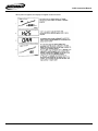
Note that the H-25C Halogen Leak Detector comes with the following accessories.
Please check also that all of these items are present.
Item Name
Power cable
Probe
Spare filter (for S-type probe)
Spare filter and o-ring (for L-type probe)
Spare activated-charcoal pack
Sensor
Power switch ON/OFF key
Spare fuse
Instruction 3015-0216
Quantity
1
1
1 set
Remarks
Length: 3 m, with grounding plug
As per type of probe ordered
1
1
2
1
For activated – charcoal pack
4
Stored inside power cable connector
(see Section 5.6)
H-25C Instruction Manual
3. Warranty
Failures occurring within one year of the purchase date will be repaired free of charge if the problem
is determined to clearly be the responsibility of BACHARACH.
Note this warranty does not apply to the sensor and filters (probe filter, activated charcoal filter).
4.
Procuring and Storing Frequently Replaced Maintenance Items
You will need to procure certain maintenance items (see page 1 - 4) on a regular basis.
We strongly recommend that you keep a stock of sensors and filters on hand at all times.
Note that the sensor will deteriorate even while in storage if exposed to humidity.
Always store the sensor in the sealed condition in which you received it.
5.
Operating Precautions
5.1 Precautions Regarding High-Temperature Parts and High-Voltage Circuits
Parts of the H-25C operate at high temperatures and voltages.
Be very careful not to touch these parts, as burns or electric shock will result.
Always take precautions to discharge static electricity from your body before touching the ROM
or associated circuits.
Exposing the ROM on the printed circuit board to strong static electric charges may cause
malfunction. Be very careful when the air is dry and static electricity is easily generated.
Instruction 3015-0216
5
H-25C Instruction Manual
5.2
Avoiding Problems
•
Please strictly observe the following:
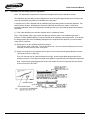
Always power the H-25C from the proper AC line voltage for its specification. Always set the supply
voltage selector switch to the proper position for the voltage in use.
Transformer damage will result if you mistakenly connect a 100 V range instrument to a 200 V range
power source.
•
Do not let the probe absorb liquid or highly concentrated halogen gas. Doing so will shorten the life
of the sensor and the activated charcoal filter, and may cause malfunction.
To keep dust and other foreign matter from being sucked into the instrument, always attach a probe
when operating the instrument.
•
Use the H-25C only indoors or in an equivalent environment.
When storing the H-25C, select a location where it will not be exposed to corrosive gases or high
humidity.
To obtain the best leak detection performance, keep the following in mind:
• Ventilate the work area well so that contaminants cannot accumulate in the air.
• The surface on which you place the H-25C should be nearly horizontal, and should not vibrate.
6. Preparing for Use
Before using the H-25C, you must set various switches according to the detection conditions (gas to be detected,
detection sensitivity, etc.), and make various adjustments (calibration gas secondary pressure, calibration request
interval, etc.) in order to obtain proper operation.
The text that follows shows the basic procedures for preparing to use the H-25C, and the measurement and
calibration procedures. For details, see Sections 2 through 4 of this manual. Note that this manual explains both
how to operate and how to maintain the H 25C. Also, in case of malfunction, this manual explains how to make
those repairs which can be made by a user. You should be sure to read this entire manual once before using the
instrument.
Note: This manual applies to instruments manufactured after September '94.
Instruction 3015-0216
6
H-25C Instruction Manual
The parts in instruments manufactured before September '94 are different.
Instruction 3015-0216
7
H-25C Instruction Manual
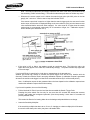
Preparing for Use & Measurement and Calibration
Preparing for Use
Operation
Remarks
1. Install the sensor
2. Set the switches
• Supply voltage selector switch
• Type-of-gas selector switch
• Measuring units selector switch
(1) Measurement unit selection
(2) Contact status selection at alarm output
(3) Measurement mode ( A-type / B-type selection
• Alarm point setting switches
• Cal. Mode (auto / manual) selector switch
• Cal. Request interval setting switch
• Search mode sensitivity switch
3.
Connect the probe
4.
Connect the power cable
5.
Apply power (turn power switch ON)
6.
Adjust cal gas secondary pressure (within 3 minutes after
power-ON)
7.
Calibrate (at least 30 minutes after cal gas secondary
pressure adjustment)
8.
Adjust speaker tone volume
9.
Allow suction of air (Power OFF)
(See Section 2.1)
(See Subsection 2.2.1)
(See Subsection 2.2.2)
(See Subsection 2.2.3)
(See Subsection 2.2.4)
(See Subsection 2.2.5)
(See Subsection 2.2.6)
(See Subsection 2.2.7)
(See Subsection 2.2.8)
(See Subsection 2.2.9)
(See Section 2.3)
(See Section 2.4)
(See Section 2.5)
(See Section 2.6)
Factory setting: R134a
Factory setting: Std. ml/s
Applies if equipped with contact
output
Factory setting: A-type mode (*1)
Factory setting: 4 hours
Factory setting: 5 times
Begin warm-up
(See Chapter 3)
(See Section 2.8)
(See Section 2.9)
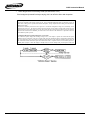
Measurement and Calibration
Operator action
1.
Apply power (turn
power switch ON)
Warm-up (180
seconds)
2.
3.
Data Display
Bar Graph Display
.(Displays all)
.“H25”
.Version No.
.“180” – “0”
(Countdown)
.Pressure
kPa {kgf/cm2}
100% : 100 {1.0}
200% : 200{2.0}
.(% value)
Speaker Tone
.Continuous tone upon detection
Ready for
measurement (search
mode)
Leak detection
Leak location search :
Search mode
(probe switch OFF : not
pressed)
Measured value (lit)
.Measured value (lit)
.Search mode alarm Percent of
point (auto-zero operates at
20% or below)
.Continuous tone upon detection
(10% or higher)
Leak flow measurement
: Pass/fail
Mode (probe switch ON
: depressed)
Calibration (auto)
Insert probe into “CAL
PORT”
.Measured value (flashing)
.Percentage of alarm point
.Intermittent tone upon detection
(100% or higher)
.”CAL” (3 seconds)
.”7” – “0”
(countdown)
.Pressure
Pull probe out when
count reaches 0. (let
suck air)
Wait for sensor output
to stabilize.
Ready for
measurement (search
mode)
.7 to 4 : Continuous tone
3, 2, 1 : Short tone
.”…”
.Sensor sensitivity
.Measured value (lit)
.(% value)
0 : Continuous tone
Note: The above table- shows the basic procedures for preparing to use the H-25C with auto calibration, and the measurement and calibration.
*1 : Check how measurements are made with the measurement mode set to A-type. Note that B-type mode is generally used for detecting leaks.
Instruction 3015-0216
8
H-25C Instruction Manual
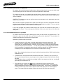
7.
Special Symbols and Formatting Used in This Manual
•
The Display State (Lit or Flashing) is Indicated in Figures as follows:
Instruction 3015-0216
9
H-25C Instruction Manual
1.
NAMES AND FUNCTIONS OF COMPONENTS
(Model codes, specifications, gases measured, calibration gas flow)
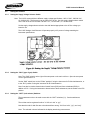
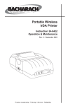
1.1 Setup Area Details
Instruction 3015-0216
10
H-25C Instruction Manual
1.2 Model Codes
MODEL
SUFFIX CODES
DESCRIPTION
H-25C
Auto CAL
function
-N
-1
No (calibrate manually with external gas
source
Yes (both auto and manual calibration
possible)
No Relay
Yes Dry Contact Relay Output
100/115 V, 50/60 Hz
120/240 V, 50/60 Hz
110/220 V, 50/60 Hz
No
Yes 0-1V DC Analog Output
English Language
Japanese Language
6 ft. mini-probe
15 ft. mini-probe
6 ft. probe
15 ft. probe (Standard)
25 ft. probe
Type L, (6 ft.) H25B tip
Type L, (15 ft.) H25B tip
Contact Output
-N
-1
Supply voltage
Analog output
Instruction Manual
Probe
Instruction 3015-0216
-5
-6
-7
-N
-1
-E
-J
-P0
-P1
-P2
-P3
-P4
-P5
-P6
11
H-25C Instruction Manual
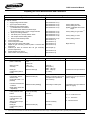
1.3 SPECIFICATIONS
Specifications
Gas Measured:
Sensor:
Measurement Range:
Alarm Point Setting Range:
Measurement Modes:
Measurement Units:
Response Time:
Calibration:
Output Signal:
Contact Output:
Displays:
Audio Speaker:
Supply Voltage;
Power Consumption:
Dimensions:
Weight:
Instruction 3015-0216
R134a or R12 gas
Cationic emission type sensor
-5
-4
9x10 to 9x10 std. ml/s, 1.5 to 150 g/yearly, 0.05 to 5.0 oz/yearly)
Note: One std. ml/s: Flow volume per second, converted to equivalent gas at 0° C 1 atm.
-6
-4
9x10 to 9x10 std. ml/s, 1.4 to 99 g/y, 0.05 to 5.0 oz/y
B-type measurement mode (for detecting leaks in a normal atmosphere
Auto zero mode: (for searching for leaks)
Auto zero hold mode: (for measuring leak flow)
A-type measurement mode (for detecting leaks in a clean atmosphere)
Search mode: (for searching for the location of leaks)
Pass/fail mode: (for measuring leak flow)
-5
Either “x10 std. ml/s” (x10-5 std. ml/s) or “g/y” can be selected
Approx. 1 second
Auto calibration (function supplied as option if specified)
Manual calibration (using “LS20B Leak Standard”)
0 to 1V DC, output resistance 1Ω max. (function supplied as option if specified
One “Alarm” point (output generated when measurement exceeds alarm setting) (function supplied as an option if
specified)
Relay state: Either an energized or de-energized state can be selected when the output is sent out.
Contact States: NO or NC, selectable
Contact rating: 2A (250 V AC, 30V DC)
Data display (3 digit numeric display)
Measured value, warm-up time countdown, cal request, idling operation, ect.
Bar graph indicator (0 to 200% in 20 segments)
Measured value, cal gas pressure – if equipped with auto cal function (indicated during warm-up and during
calibration), sensor sensitivity (at cal completion), etc.
Malfunction alarm display
“AIR FLOW” (measured gas intake flow), “CAL FAIL” (EE Prom failure, calibration gas pressure low, unable to
calibrate)
Type of gas display
Unit
Probe indicator (LED)
Indicates leak detection, cal request, cal operation in progress
Leak detection, cal request, cal operation in progress
100/115V AC, 50/60 Hz, 110/220 V AC, 50/60 Hz, or 120/240 V AC, 50/60 Hz
100VA
148 H x 210 W x 330 D mm, (5-13/16 H x 8¼ W x 13D in)
Approx. 10 kg (22lbs)
12
H-25C Instruction Manual
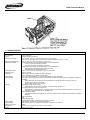
1.4 Probes
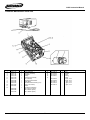
1.5 Accessories and Maintenance Tool List
Item Name
Filter (For S-type probe)
Filter, O-ring (for L-type probe)
Activated – Charcoal pack
Sensor
Fuse (rating: 3.15A 250V
Disc Filter
Freon filler fitting
Instruction 3015-0216
Part Number
3015-1820
3015-1705
3015-2418
3015-0807
3015-1630
3015-2476
3015-1433
Remarks
Unit of purchase : 1 piece
Unit of purchase : 1 set (one piece each)
Unit of purchase : 1 set (five pieces)
Unit of purchase : 1 piece
Unit of purchase : 2 pieces
Unit of purchase : 1 piece
Used when filling tank with liquid freon for use in
calibration
13
H-25C Instruction Manual
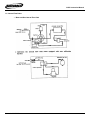
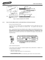
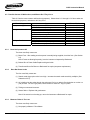
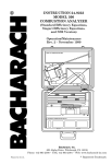
1.6 Internal Flow Paths
• Measured Gas Internal Flow Path
Instruction 3015-0216
14
H-25C Instruction Manual
2.
PREPARING FOR USE
This section explains the switch settings and other procedures that must be done to prepare the instrument for
use. For operating instructions, see Section 4.
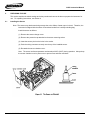
2.1
Installing the Sensor
Note: The sensor may deteriorate during storage due to the effects of water vapor in the air. Therefore, the
instrument is shipped with the sensor removed and sealed in a humidity-excluding bag.
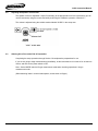
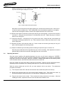
Install the sensor as follows:
(1) Remove the sensor changer cover.
(2) Remove the protective cap attached to the sensor mounting socket.
(3) Insert the sensor pins into the holes in the socket.
(4) Push the tubing connector securely onto the top of the installed sensor.
(5) Re-attach the sensor chamber cover.
Note: The sensor surface temperature reaches about 200°C (392°F) during operation. Always keep
the sensor chamber cover in place so as to prevent fires and other accidents.
Instruction 3015-0216
15
H-25C Instruction Manual
2.2
Setting the Switches
2.2.1
Setting the Supply Voltage Selector Switch
Note: The H-25C comes with three different supply voltage specifications, 100/115 VAC, 100/200 VAC,
Or 120/240 VAC. The frequency can be either 50 or 60 Hz. Use the supply voltage selector switch
on the rear of the H-25C to select 100 and 115 V, 110 and 220 V, or 120 and 240V.
Set the supply voltage selector switch to the side labeled appropriate to the AC line voltage you
intend to use.
The H-25C Halogen Leak Detector will operate properly o AC power of voltage matching the
instrument specifications.
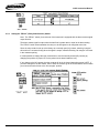
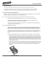
2.2.2
Setting the “GAS” (type of gas) Switch
Note: The “GAS” switch is at the right of the setup area on the main unit front. Open the setup area
cover to gain access to it.
Set the “GAS” switch lever to the “R134a” position if using the instrument for R134a leak detection, or
to the “R12” position if using the instrument for R12 leak detection.
Note: Can also be used to detect leaks of certain freons (R22) and freon substitutes (R502) in
addition to R12. If using the instrument to detect leaks of these substances, set the switch to the R12
position.
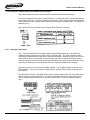
2.2.3
Setting the “UNIT” (unit selector) Switches
The measurement units to be used are set with the “UNIT” switches (1,2). Set the switches as
follows.
The unit that can be registered is either “X 10-5 std. ml/s” or “g/y”.
Note that the units for leak flow are to be selected from among “X10-5 std. ml/s”, “g/y”, and “oz/y”
Note: The selected units are indicated in the display area during measurement.
Instruction 3015-0216
16
H-25C Instruction Manual
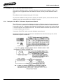
2.2.4
Setting the “RELAY” (Relay State Selector) Switch
Note: The “RELAY” switch (3) must be set if the instrument is equipped with the alarm contact signal
output function.
The alarm contact signal is output when the leak flow is greater than or equal to the alarm setting.
The “RELAY” switch selects whether the relay is to be energized or de-energized at the time.
Since the relay contact is set up at the factory as a normally open (N)) contact, selecting “energize”
will result in the contacts closing when the signal is output, whereas selecting “de-energize” will result
in the contacts opening.
It is also possible to change the relay connections to use the normally closed (NC) contact (by
changing the position of jumper JP1 on the printed circuit board inside the unit).
If you change to the NC contact, then the contacts will be in the closed state when power is OFF. If
you have changed to the NC contact, then to have the contacts go to the closed state at time of alarm
you must set the switch lever to the “de-energize” position.
Instruction 3015-0216
17
H-25C Instruction Manual
2.2.5 Setting the “MODE” (Measurement Mode Selector) Switch
Select the measurement mode using the MODE (measurement mode selector) switch.
There are two measurement modes, A-type and B-type. For detecting leaks in a normal atmosphere,
set the switch to B-type. (The factory setting is A-type mode.) Select A-type mode if the atmosphere
at the measurement site is always clean (extremely small quantity of unwanted gas). For details, see
Subsection 4.2.2
Note: When first using this switch, select A-type mode and check it is working.
2.2.6
Setting the Alarm Point
Note: Alarms (intermittent tone from the speaker, flashing indicator lamp) are output when the
measured value is greater than or equal to 100% on the bar graph. The value at which the alarm
output trips is called the alarm output trips is called the alarm point. Although this point can be freely
set by the user, there are restrictions on the lower limit. Also, when A-type measurement mode is
selected, the search mode sensitivity is restricted depending on the value set (see Subsection 2.2.9).
Generally, set the alarm point used to detect leaks to the highest possible value of leakage.
The alarm point value is set using the “ALARM” switches. The “ALARM” switches consist of three
digital switches. The two on the left set a 2-digit number, and the “EXPNT” switch on the right sets
the exponent.
Note that if the instrument is equipped with the alarm contact output function, then the contact signal
will also be output at alarm output time. The alarm annunciation and contact signal will remain on
until the measurement value drops to 20% below the alarm point. (That is, a hysteresis band of
20%.)
Instruction 3015-0216
18
H-25C Instruction Manual
2.2.7 Setting the “CAL” (Calibration Mode Selector) Switch
There are two calibration modes: automatic calibration mode and manual calibration mode. If the
instrument is not equipped with the auto calibration function, then only manual calibration mode is
valid.
The calibration mode is selected using the “CAL” switch.
To select auto calibration mode you set the switch to the “AUTO” position, and to select the manual
calibration mode you set the switch to the “MANUAL” position.
2.2.8
Setting the “CAL INTVL” (Calibration Request Interval) Switch
The H-25C can issue requests for calibration operations at fixed intervals when A-type measurement
mode is selected. At the time of the calibration request, the speaker sounds an intermittent tone for
five seconds, and “CAL” is displayed with flashing in the display area (a maximum of ten times during
a 15-second period in the measurement mode. The interval between calibration requests can be set
in 1-hour increments up to 10 hours.
You use the “CAL INTVL” switch to set the calibration request interval.
Note that the calibration request interval timer is activated at the end of the warm-up time, and is
reset whenever power is turned OFF.
Instruction 3015-0216
19
H-25C Instruction Manual
2.2.9
Setting the “GAIN” (Search Mode Sensitivity) Switch
The setting results here are valid only for the search mode I A-type measurement mode.
Raising the sensitivity in order to detect lower values makes it easier to locate leaks.
The sensitivity can be raised in search mode in A-type measurement mode, making it possible to find
leaks with up to ten times (integer factor) the sensitivity of pass/fail mode used to measure leak flows.
However, the sensitivity multiplication factor is restricted by the alarm contact setpoint.
Caution: In search mode, the 20% point on the bar graph is called the search mode trigger
point. Sensor outputs less than the search mode trigger point are assumed to be
background potentials, and are displayed as 0% by the auto-zero function..
This means that in search mode you cannot detect leakage levels lower than the search mode
trigger. Note: this does not apply in special measurement mode. B-type measurement mode is
excluded.
Instruction 3015-0216
20
H-25C Instruction Manual
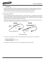
2.3
Connecting the Probe
Connect the accessory probe to the “PROBE” connection socket on the instrument front panel and secure it
with the lock ring.
Note that the probe connection socket gas intake port is covered with a protective cap, which you must
remove before connecting the probe.
Note: The Model H-25C detector can be fitted with a probe to satisfy all needs.
2.4
Connecting the Power Cable
The power cable supplied with the instrument (length, 3 m) has a plug with a grounding pole. First, make
sure that an AC power receptacle (socket) compatible with this plug is available nearby. The power
consumption of this instrument is about 100 VA.
After making sure that you can obtain the line power for which the supply voltage selector switch is set,
connect the power cable to the connector on the rear of the instrument. Then connect the plug on the other
end to the AC power receptacle.
2.5
Applying Power (Turning the Power Switch ON)
Note When using this instrument, always keep in mind that it contains parts that operate at high
temperatures (the sensor), and circuits where high voltages are present, and take care to avoid burns and
electric shock. Also, be careful where you place the probe, so that you never allow it to such in any liquid.
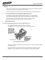
When you first use the H-25C Halogen Leak Detector, you must adjust the calibration gas secondary
pressure within three minutes of the time that you apply power (if it has the auto calibration function). So,
before turning ON the power switch, remove the cover from the main unit.
Remove the cushioning material (sponge) inserted between the pump and the printed circuit.
The instrument will begin operating as soon as you turn the power switch ON. The power switch is turned
ON and OFF with a key. Insert the key supplied in the accessories into the power switch keyhole and turn
to the right (power switch ON).
When you apply power, the instrument will go immediately into warm-up mode. Per form the secondary
gas pressure adjustment at once (see Section 2.6).
Instruction 3015-0216
21
H-25C Instruction Manual
When power is applied, the display will appear as shown below.
Instruction 3015-0216
22
H-25C Instruction Manual
2.6
Calibration Gas Secondary Pressure Adjustment
Note: This adjustment is required in the instrument equipped with the auto calibration function.
The calibration gas secondary pressure adjustment is done during the approximately three minutes of the
warm-up period when the pressure is indicated on the bar graph.
In principle, the H-25C is shipped with the calibration gas secondary pressure temporarily adjusted. This
section shows, however, the adjustment should be made with the tank valve closed. If it has been
temporarily adjusted, make the re-adjustment according to step (3) of the following adjustment procedure
give below.
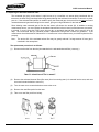
(1) First, make absolutely sure that the regulator valve is completely closed.
Note: If the regulator valve is open at the time that you open the valve on the calibration gas tank, a
pressure of nearly 600KPa (6kgf/cm2) may be imposed on the calibration gas tubing system. Even though
the tubing system will not be immediately damaged even if subjected to this pressure, you should make
every effort to avoid this.
(2) Always pull up on the regulator knob when turning it.
Fully open the valve on the tank. Turn the handle on top ¾ of a turn counterclockwise until you feel it
hit a stop, at which point the valve is fully open.
(3) Slowly turn the knob on the regulator valve to open it so as to bring the bar graph indication near the
150% point (147kPa {1.5kgf/cm2}).
If you turn the knob too far (raise the pressure too high), loosen the gas bleed plug and wait for the
pressure to drop to a value below the target, then tighten the gas bleed plug and repeat the adjustment
Note: Loosening the gas bleed plug will result in the outflow of much more gas than the amount that
flows out from the “CAL PORT”.
Instruction 3015-0216
23
H-25C Instruction Manual
The above operations complete the calibration gas secondary pressure adjustment. Replace the cover of
the main unit.
When warm up ends, the instrument will go into measurement mode.
The bar graph indication displays the amount of
leakage. When the probe switch is not being
pressed, the instrument is in search mode and the
indicated value is based on the value of the search
mode alarm point value. The data display area
shows the type of gas selected, and the displayed
value and units. Pressing the probe switch to
place the instrument in pass/bail mode causes the
displayed value to begin flashing.
Note that calibration gas is always flowing out from the “CAL PORT”. Therefore, once the calibration gas
secondary pressure has been adjusted, that adjustment need not be done again until the calibration gas
(R134a) is exhausted. However, when the instrument not adjusted even temporarily is first adjusted, the
pressure may vary slightly in the initial period. You should check the pressure indication (displayed during
warm-up and during calibration operations) after one day or more has passed and repeat the adjustment if
the pressure is not in the permissible range.
2.7
Calibration
After the instrument has finished warm-up and gone into measurement mode, you can perform a
calibration. However, since it is preferable to wait until the sensor temperature has reached its final value,
and the instrument as a whole is in a thoroughly stable state, we recommend that you wait at least 30
minutes after the end of warm-up before calibrating.
See Chapter 3 for the calibration procedure.
Instruction 3015-0216
24
H-25C Instruction Manual
2.8
Adjusting the Speaker Tone Volume
The speaker volume is adjustable. Adjust if necessary (to the appropriate level for the area where you will
use the instrument) using the tones heard while performing the calibration operation of Section 2.7.
The volume is adjusted using the variable resistor labeled “AUDIO” in the setup area.
2.9
Allowing Air to Flow at the End of Preparation
Completing the setup operations through Section 2.8 completes the preparations for use.
If you are not going to begin measurements immediately, let the instrument suck in clean air for at least one
minute, and then set the power switch to OFF.
Note: Set the MODE switch to B-type measurement mode when checking operations in A-type
measurement mode.
(When detecting leaks in a normal atmosphere, set the switch to B-type.)
Instruction 3015-0216
25
H-25C Instruction Manual
3. CALIBRATION
The Model H-25C Halogen Leak Detector performs calibration when the detector is first used (including sensor
sensitivity adjustment and sensor replacement) or when " calibration request " appears in A-type measurement
mode. Calibration data are maintained for about three weeks after calibration, then returned to the default
values, after which the instrument must be calibrated again.
The calibration request message appears only in A-type measurement mode; it appears after power-on, then
again after repeated fixed intervals (calibration request interval). The calibration request message will also
appear if the measured value in search mode is at or above the "trigger point"( see Subsection 4.2.1 ) for more
than 20 seconds.
Calibration is performed using a leak standard that provides a freon gas leak of known flow.
There are two calibration alternatives: auto calibration and manual calibration. The auto calibration method
uses a built-in leak standard, and can be used only if the instrument is equipped with the auto calibration
option.
When performing a calibration by the manual method, you must change the "ALARM" (alarm point) setting
value to the leak flow of the leak standard, but this is not necessary in the case of auto calibration.
Instruction 3015-0216
26
H-25C Instruction Manual
BACHARACH
Instruction 3015-0216
27
H-25C Instruction Manual
3.1
Auto Calibration
This auto calibration procedure can be used only if the instrument is equipped with the auto calibration
option. Auto calibration is not possible when the measurement mode is set to B-type; always set the
mode to A-type for auto calibration.
3.1.1
Setting the Switches
Auto calibrations are performed with the " CAL " switch in the setup area set to the AUTO " position.
Re-setting of " GAS " and " UNIT " switches is not necessary.
Note : The calibration gas always flows out from the 'CAL PORT" at a flow rate corresponding to the
secondary pressure.
Note that the calibration gas used in the H-25C's optional built-in leak standard is R 134a. At a
secondary pressure of 170 kPa {1.7 kgf/cm2} this cal gas will flow out from the " CAL PORT " at a rate of
9 X 10⁻⁵ to 11 x 10-5 std. ml/s.
3.1.2
Operator Actions and the Calibration Operation
Inserting the probe tip into the "CAL PORT” causes a switch inside the port to turn on, starting calibration.
________________________________________________________________________________________________
_
CAUTION:
If an S - probe is to be used, remove the tube for introducing gas. Inserting the tube for
introducing gas into the "CAL PORT' may damage the spring switch in the detector. If the tube is removed,
exercise care not to lose the filter that is in the probe.
________________________________________________________________________________________________
_
Instruction 3015-0216
28
H-25C Instruction Manual
Continue to hold the probe in the inserted position until the countdown (starting from 7) on the display
reaches 0. (Leave the instrument in search mode; do not press the pass/fail switch on the probe.)
When the countdown reaches 0, the instrument’s internal circuits store the data required for calibration.
Disconnect the probe from the “CAL PORT”, and let it such in clean air.
Instruction 3015-0216
29
H-25C Instruction Manual
3.1.3
What to Do If the CAL FAIL Indicator Appears
If the CAL FAIL indicator appears during calibration, no calibration is performed. When CAL FAIL
indicator appears, one of the following five fail codes is displayed on the data display area while the
instrument stabilizes.
Take appropriate action for the displayed fail code.
E - 1 (no sensor sensitivity)
E - 2 (sensor sensitivity too low)
E - 3 (sensor sensitivity too high)
E - 4 (calibration gas pressure adjustment failed)
E - 5 (unstable sensor sensitivity)
(1)
E-1 (No Sensor Sensitivity)
This fail code is displayed if the sensor does not detect the calibration gas. The three most likely
possible reasons for this are :
•
Sensor sensitivity is unstable due to poor adjustment, or the sensor has reached the end of its
service life.
[Action] Try repeating the calibration. If " CAL FAIL " appears again, see Subsection 6.2.8 and
take appropriate action.
• The calibration gas is not being sucked in from the probe AM FLOW " is displayed ).
• The capillary is plugged and the calibration gas cannot flow out from the CAL PORT.
(2)
E .2 (Sensor Sensitivity Too Low) or E - 3 (Sensor Sensitivity Too High)
This fail code is displayed if the sensor sensitivity is outside the calibration range.
[ Action] Adjust the sensor sensitivity.
The tolerance range is 60 to 150% on the bar graph (the 150% end of this range is the lower
sensitivity end). Sensitivity outside the tolerance range is indicated as follows:
Use the HEATER variable resistor in the setup area to adjust sensor sensitivity. The HEATER
variable resistor changes the voltage of the sensor heater. If the sensor sensitivity is too low, turn the
knob clockwise. If the sensitivity is too high, turn the knob counterclockwise.
This adjustment cannot be completed simply by watching the sensitivity display while turning the
knob. Repeatedly check the sensitivity by performing calibration after each adjustment (turn the knob
about 30 to 90 degrees each time). Wait at least three minutes after each adjustment before
performing the calibration so that the sensor temperature has time to stabilize. Repeat the
adjustment and calibration procedure until the bar graph reaches 90, 100, or 110%.
Instruction 3015-0216
30
H-25C Instruction Manual
3.2
Manual Calibration
Use the manual calibration method ff the instrument is not equipped with the auto calibration option.
Manual calibration is possible in both A-type and B-type measurement modes.
Note : An LS - 20B Leak Standard is required for manual calibration.
3.2.1 Setting the Switches
Manual calibration is done in manual calibration mode. Set the " CAL " switch in the setup area to the "
MANUAL " position.
Also set the following three switches to match the type of gas, leak flow, and leak flow units of the LS 20B to be used for calibration.
•
•
•
Set the " GAS " switch to the position for the type of gas.
Set the "UNIT" switches for the proper units.
Set the "ALARM' switches to the leak flow value.
3.2.2 Operator Actions and Calibration Operation
Start the calibration procedure as follows:
(1) Insert the probe into the H-25C "CAL PORT" to apply an ON signal through the spring switch.
Note : When an S-probe is used, carry out this operation after removing the tube for introducing gas.
(2) After applying the ON signal, immediately pull the probe away from the "CAL PORT" and, with the
instrument in search mode (probe switch not depressed), let the probe suck in clean air. The
instrument will start its calibration operations after about seven seconds.
When it starts the calibration operation, the instrument will output a tone from the
speaker. At this time, you must perform the following actions:
(3) With the probe switch not pressed, touch the probe tip to the LS - 20B PROBE port. Keep the probe
touching until the reading on the display stabilizes.
(4) When the value stabilizes (wait at least ten seconds), press the probe switch once (for less than 0.5
sec.). The instrument will store the calibration data at that time.
(5) Immediately pull out the probe and allow it to suck in clean air.
After completing the calibration operation, the instrument will go into measurement mode. If you changed
any switch settings, return them to their original condition.
3.2.3 What to Do If CAL FAIL Appears
If CAL FAIL appears during calibration, calibration is not performed. When the CAL FAIL indicator
appears, one of the following three fail codes is displayed on the data display area while the instrument
stabilizes.
E - 1 (no sensor sensitivity)
E - 2 (sensor sensitivity too low)
E - 3 (sensor sensitivity too high)
Refer to Subsection 3.1.3 for details of what to do when the fail code appears.
Instruction 3015-0216
31
H-25C Instruction Manual
3.2.4 What to Do If the Alarm Code Appears
Unlike when the fail code is displayed, calibration is performed when the alarm code is displayed. When
the data for calibration approaches the allowable limit, an error code (A-1 to A-3) is displayed for about
four seconds before completing calibration.
The two alarm codes are as follows; take appropriate action depending on the alarm code displayed.
A - 1 (high background voltage)
A - 2 (short calibration gas suction flow rate)
A - 3 (short calibration gas suction flow rate)
Refer to Subsection 3.1.4 for details of what to do when the alarm code appears.
Instruction 3015-0216
32
H-25C Instruction Manual
4.
Measurement Operations
This chapter explains how the H-25C works, and how to detect leaks with it. Note that before doing any of the
operations described here, you must first complete the operations described in Section 2 (switch setup, etc.) to
prepare the H - 2 5C for use.
4.1
Choosing a Location for the H-25C, and Getting Ready to Start Measurement
4.1.1
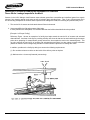
Choosing a Location
The H-25C Halogen Leak Detector should be placed on a flat, horizontal surface such as a bench or
table top when in use.
Since it is fairly heavy at about 10 kg (22 lb), the main unit will not easily slide off the table or bench even
if you pull on the probe. However, consider that risk and make sure that you choose a stable surface on
which to place it; a fall to the floor will probably cause the instrument to fail.
Keep in mind that instrument needs a location where the air is clean and pure, and a surface free of
vibration. Facilitating leakage inspections varies depending on whether or not leakage inspection areas
are clean; the service life of sensor and activated-charcoal filters also vary. for reference, examples of
facilities that rid the atmosphere of unwanted gases where leakage inspections are made are given at the
end of the manual (after chapter 6).
4.1.2
Getting Ready for Measurement
(1) Connecting the Power Cable
Supply the H-25C with AC power of 100 / 115 V or 120 / 240 V, as appropriate to its specifications
and the supply voltage selector switch position.
Connect the plug on one end of the power cable to the power connector (socket) on the main unit,
and then connect the other end to the AC line receptacle.
Use the supply voltage selector switch on the rear of the H-25C to select 100 and 115 V, 110 and
22OV, or 120 and 24O V.
CAUTION:
Never connect power in the 200 V range to an H-25C with the 100/115 V specification, or
to one whose supply voltage selector switch is in the 120 V position; the instrument will be
damaged.
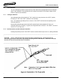
(2) Wiring the Analog Signal Output (if equipped with analog signal output function)
If you wish, you can order the H-25C with a function that outputs the measured value as a 0 to 1 V
DC analog signal. If your instrument has this function, connect the wiring from the instrument to the
recorder or other destination. (See Figure 4.1.)
Note that the output resistance is less than 1Ω. The 0.5 V level of the 0 to 1 V DC output signal
corresponds to the alarm point setting value. This relationship always remains the same, and is
unaffected by sensitivity changes in search mode, etc.
Instruction 3015-0216
33
H-25C Instruction Manual
(3)
Wiring the Alarm Contact Output Terminals (if equipped with contact
output function)
(3) If you wish, you can order the H-25C with a function that outputs a contact signal when the measured
value exceeds the alarm point. If your instrument has this function, connect the wiring from the
instrument to signal destination. (See Figure 4.1.)
Note: See Subsection 2.2.4 regarding the state of the contacts when the alarm contact signal is
output.
The maximum allowable voltage across the contacts is 220 V DC or 250 V AC. The maximum
allowable current is 2 A. Note that if electrical noise is present at the connected load (or generated
by the switching action), you should connect a noise killer, or surge suppression network, across the
terminals, or take other appropriate countermeasures, since such noise may cause improper
operation.
(4) Turn the Power Switch to the ON position to place the H-25C in operation. Insert the key provided
into the keyhole in the power switch, and turn clockwise (to the right). Connect the probe before
doing turning on power, if it is not already connected.
The H-25C will go into measurement mode after about 180 seconds of warm-up. During the warmup time or immediately after transferred to the measurement mode, check the following.
•
Make Sure that the Fan is Running
The fan serves two purposes. One is to bring cooling air into the instrument. The other, if the
instrument has the auto calibration option, is to maintain a consistent atmosphere inside the
instrument. Thus it is vital that the fan be turning properly.
Note: Calibration gas is normally flowing out not only from the ' CAL PORT " probe insertion
opening, but also from the air intake hole (on the inside of the 'CAL PORT" section) as wen. In
auto calibration the probe inserted in the " CAL PORT " takes in air from inside the instrument
through this hole, together with the calibration gas. If the fan steps, calibration gas will
accumulate in the air inside the instrument, and its effects will make accurate calibration
impossible.
•
Instruction 3015-0216
Check the Cal Gas Secondary Pressure Displayed during Warm-up. (If auto calibration option is
installed.)
The calibration gas secondary pressure is normal if the indication is in the 100 to 200% range.
Auto calibration can be performed if this indication is normal or, even if abnormal, is not less than
50% (although the " CAL FAIL " indicator will be flashing when in measurement mode). If it is
below 50%, auto calibration is not possible.
34
H-25C Instruction Manual
•
Is the "AIR FLOW" Indicator On ? (Check in measurement mode)
The " AIR FLOW" indication tells you that the intake air flow is being reduced due to clogging of
the probe air filter, or some other cause.
Under normal conditions, the instrument will suck in a bout 4.5 ml/s of measurement gas from the
probe. If the intake flow remains below about one quarter of this value for about 30 seconds, "
AIR FLOW" will be displayed.
If "AIR FLOW" is displayed, replace the probe filter. If the intake flow does not recover even
though you have replaced the probe filter, then there is some other problem. (See Chapter 6.)
Note that even if “ AIR FLOW" is displayed, you may still be able to measure and calibrate
normally in some cases. However, even in such cases we recommend that you take
maintenance actions to restore intake flow to its proper value as soon as possible.
Instruction 3015-0216
35
H-25C Instruction Manual
4.2
Measurement
4.2.1
Measurement Modes
The H-25C has two main measurement modes, A-type and B-type. Use the MODE switch
to select the mode to be used (see Subsection 2.2.5).
A-type mode is used if there is very little unwanted gas in the surrounding atmosphere and
its concentration is settled, while B-type mode is used if there is a relatively high proportion
of unwanted gas in the atmosphere and its concentration fluctuates. Generally, use B-type
for detecting leaks since there is usually unwanted gas in the atmosphere in the facility
when measuring leaks.
B-type mode has two sub-modes: auto-zero mode and auto-zero hold mode. Auto-zero
mode operates when the probe switch is off (not depressed ). When the probe switch is on
pressed), the instrument operates in auto-zero hold mode.
4.2.2
Searching for the Location of a Leak in B-type Mode
To find the location of a leak, use auto-zero mode (probe switch off ). To identify the location, bring
the probe tip to within 1 cm of the leak for several seconds. The intake flow of the probe is about 4.5
ml/s, with a response time of about one second.
CAUTION : Be very careful that no liquid is sucked into the probe, since this may damage the
instrument.
In auto-zero mode, if the sensor output is greater than or equal to the alarm point set value, the
speaker sounds an intermittent tone ( frequency : 1000 Hz approx. ), and the probe indicator lamp
lights. The tone and the lamp are switched off when the value is 20% below the alarm point.
If the H-25C is equipped with an alarm contact output, then if the leak rate reaches the alarm point, a
contact signal is output. This contact signal is also switched off when the value falls to 20% below
the alarm point.
In auto-zero mode, the background potential is always updated (delay time: 5 to 10 seconds).
Therefore, the indicated value brings back to 0% over several seconds even when a leak is detected.
In this mode, the detection sensitivity cannot be increased such as in search mode in A-type mode.
Note : When the auto-zero function is in operation, the leak rate cannot be measured correctly. To
measure the leak rate, perform the auto-zero operation in the gas concentration of normal
atmosphere, and then hold the auto-zero value ('auto-zero hold mode").
4.2.3
Searching for the Location of a Leak in A-type Mode
To find the location of a leak, use search mode (probe switch off). The procedure for identifying the
location of a leak is the same as in auto-zero mode in A-type mode.
CAUTION:
may result
1.
Be very careful that no liquid is sucked into the probe; failure of the instrument
2.
If the sensitivity multiplier setting is too low, the instrument may not respond even
if a leak is present. On the other hand, if it is set too high, the instrument may
respond to the ambient gas level, making it difficult to identify the site of the leak.
Freon gas detection is performed by the following actions.
•
Instruction 3015-0216
In search mode, the 100% point on the bar graph indicator becomes the search mode alarm
point.
36
H-25C Instruction Manual
Note : The search mode alarm point simply represents the value of the 100% point determined by
the sensitivity ("GAIN" switch setting). The search mode alarm point does not initiate any action.
•
Whenever the sensor output level is below the search trigger point (the 20% point on the bar
graph), the " auto-zero " function acts to keep the indication at 0%.
If the sensor output level is equal to or higher than the search trigger point, the auto-zero function
action stops, and the value is displayed taking as the zero reference (0%) point the last auto-zero
value measured before auto-zero action stopped. If a value equal to or higher than the search
mode trigger is encountered continuously for 20 seconds or longer, the " calibration request "
action will start (see Subsection 4.2.3).
•
If the value is 10% or higher, the speaker sounds an continuous tone. The higher the value, the
higher the tones (approx. 10 to 2000 Hz, hierarchically change). The probe indicator lamp lights with
the tone change.
If you have difficulty in searching for a leak due to unwanted gas in the atmosphere I
Ambient gas levels high enough to exceed the search trigger level will not only interfere with the
discovery of leaks, but will also result in annoying calibration requests. (A calibration request is generated
whenever the search mode trigger level has been exceeded continuously for a 20-second period.)
Note : A calibration request is also generated when the time elapsed on the calibration request timer
reaches the calibration request interval time setting.
If you have this problem, do one of the following:
•
Pull the Nominal 0% Point Up to the Level that has exceeded the Search Trigger Point:
Pressing the probe switch one time only for not more than 0.5 seconds will actuate the autozero
function, and update the background potential. (Note that pressing it more than 0.5 seconds will
provide pass/fail mode.)
This method is effective for locating leaks when the background potential does not change.
•
Lower the Sensitivity Multiplier:
If the sensitivity multiplier has been set to 10 or to 5, changing to a lower multiple (this will increase
the search mode alarm point value) may have a favorable effect.
Instruction 3015-0216
37
H-25C Instruction Manual
•
Select B-type Mode for Detecting Leaks (see Subsection 4.2.3)
If the background potential is always varying, this is an effective aid to leak inspection.
[Auto-zero]
The sensor will output some voltage even for pure air. This is called the background voltage (or potential, or level). If
freon and I or other gases are present in the ambient atmosphere, voltage components due to those gases will add to the
background voltage.
The auto-zero function processes the sensor signal so as to make the background voltage serve, electrically, as the
nominal zero point level. The auto-zero function operates when the sensor output in search mode is below the level
equivalent to the search mode trigger point. This also means that any leak in the range where the auto-zero function
operates will not be detected. Therefore, you must exercise care in the use of this feature if it is important to know for
sure whether any leak is present.
[“Calibration Request Operation] (functions in A-type mode)
A “calibration request" displays the flashing message “CAL", and outputs a speaker tone and flashes the probe
indicator lamp in synchronism. After five seconds of this action, the instrument returns to measurement mode display
for 15 seconds, but if you do not perform a calibration within that time, it will output the calibration request again. If
this alternation between calibration request and measurement mode is repeated ten times, the instrument goes into a
standby mode. (Chapter 3 shows the display in standby mode.) To cancel standby mode, press the probe switch once
Instruction 3015-0216
38
H-25C Instruction Manual
4.2.4
Leak Rate Measurement in B -type Mode
To measure how much freon gas is leaking from a leak you have found, use auto-zero hold mode.
The instrument goes into this mode when you hold the probe switch depressed.
To measure the leak rate, you basically just hold the probe tip near the site of the leak (within 1 to 5
mm). Note, however, that in practice some differences in technique may be required, depending on
various conditions.
CAUTION : To measure the leak rate, perform the auto-zero operation in the atmospheric gas, then
hold the auto-zero value.
When the sensor output is greater than or equal to the alarm point set value, the speaker sounds an
intermittent tone (frequency: 1000 Hz approx.), and the probe indicator lamp lights. The tone and the
lamp are switched off when the value is below the alarm point.
If the H-25C equipped with an alarm contact output, then if the leak rate reaches the alarm point, a
contact signal is output. This contact signal is switched off when the value falls to 20% below the
alarm point.
4.2.5 Leak Rate Measurement in A -type Mode
To measure how much freon gas is leaking from a leak you have found, use pass/fail mode. The
instrument goes into this mode when you hold the probe switch depressed. The procedure for
measuring the leak rate is the same as in B-type mode.
Operation in pass/fail mode is as follows:
•
In pass/ fail mode, the 100% point on the bar graph display becomes the alarm point. The
measured value in the display area is displayed with flashing. The alarm point is the value
selected with the "ALARM" switches. Normally, you will set them to select the highest allowable
value that will pass the leak inspection. You can change the alarm point setting value while the
H-25C is operating. Changing the alarm point will cause the status of the "ALARM' switches to
be displayed in the data display area for about three seconds after the change.
Note : When changing the alarm point, keep in mind its interactions with the "GAIN" switch setting
(Subsection 2.2.9).
•
In pass/fail mode, the instrument holds the last auto-zero value. Therefore, once you have put
the instrument in pass/ fail mode, any changes in the background potential will be treated as leak
rate data.
If the atmosphere does not stabilize thus making it difficult to measure the leak rate, try using Btype mode (see Subsection 4.2.4).
•
If the leak rate is at or above the alarm point, the speaker will emit an intermittent tone
(frequency: approx. 1000 Hz), and the indicator lamp on the probe will light. The tone and the
lamp are switched off when the value falls below the alarm point. If the H-25C is equipped with
an alarm contact output, then when the leak rate reaches the alarm point, a contact signal is
output. This contact signal is switched off when the value is 20% below the alarm point.
Instruction 3015-0216
39
H-25C Instruction Manual
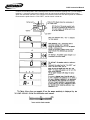
4.2.6
How to Check the Measured Value, and Possible Reasons for Abnormal Operation
[How to Check the Measured Value]
To check for error in the measured value, set a leak standard for a known constant leak rate, let the
probe suck in the gas, and examine the indicated value. Use pass/fail mode during this
measurement.
Note: If the instrument has the auto calibration option to display current calibration-gas flow rate in
the data display section, set the ' UNIT " switch as shown in the figure below. Note that the displayed
value is the result of computation based on the secondary pressure of the calibration gas. The
displayed value may differ from actual value if dirt is attached in the capillary or the gas leaks from
the gas bleed plug.
[Cause of Abnormal Symptoms]
If the instrument shows symptoms of abnormal operation during measurement or calibration, the
most likely reasons are as follows:
•
"AIR FLOW" indicator is ON.
Probe filter is clogged. (See Section 5.1 for corrective action.)
•
Leak rate displayed is too high.
Activated charcoal filter performance is deteriorating. (See Section 5.2 for corrective action.)
Instruction 3015-0216
40
H-25C Instruction Manual
4.2.7
•
" Calibration requests " are being issued too frequently. Activated charcoal filter performance is
deteriorating.
•
" CAL FAIL " indicator is displayed (flashing).
Calibration gas freon in the tank has been used up. (See Section 5.3 for corrective action.)
•
Unable to calibrate ("CAL FAIL" displayed).
Sensor performance has deteriorated. (See Section 5.4 for corrective action.)
Turning the Power Switch OFF
The usable life of the sensor and the activated charcoal filter are highly dependent on the time that
power is ON (the time that gases to which the instrument is sensitive are being drawn in). We
therefore recommend that you turn the instrument power switch OFF if you do not intend to make any
measurements for a period of several hours.
Note that before turning the power switch OFF, you should always let the instrument draw in clean air
for at least one minute.
Instruction 3015-0216
41
H-25C Instruction Manual
4.3
R-12 Leak Detection
The leak detector sensor for measuring R-134a requires a much greater sensitivity than for
measuring R-12. Since the H-25C has a very sensitive sensor, it generates a very large output for R12. This causes any unwanted gas in the atmosphere to have large effects, resulting in disturbances,
and this also affects the service life of the sensor. If the H-25C is used for detecting R-12 leaks then
perform the following calibration procedures.
Note that the LS-20B Leak Standard is required for calibration.
4.3.1 Switch Setting
Perform calibration in manual calibration mode. Set the switches in the setup area as follows :
GAS switch: set to R134a
CAL switch: set to MANUAL
UNIT switches: set to ml/s
ALARM switches: set the leak rate set in the LS-20B
4.3.2 Calibration Procedures
Perform calibration as follows :
(1) Insert the probe into the CAL PORT and provide ON signal for the spring switch. In case of the
S-type probe, the tube for introducing gas must be removed to perform this operation.
(2) After providing ON signal, immediately remove the probe from the CAL PORT and suck in clean
air without pressing any switch. The speaker sounds a tone about seven seconds later, then
calibration starts.
(3) While in search mode, bring the probe tip near the LS-20B PROBE and keep it close until the
value on the display stabilizes.
(4) When the display stabilizes (after about 1 0 seconds ), press the probe switch once (for less than
0.5 sec.). Immediately pull out the probe from PROBE and suck in clean air. Use the reading at
this time for the calibration data.
(5) Verify that the sensor sensitivity displayed on the bar graph area is between 60 and 100%. If it
exceeds 100%, turn the HEATER variable resistor clockwise, and repeat the procedures from (1)
until it lies within the range. If it does not reach 60% (Note), turn the HEATER variable resistor
counterclockwise( generally, turn the knob three or four times more than the factory setting), and
repeat the procedures from (1) until it lies within the range.
Note - CAL FAIL lamp lights when 50% or less
Instruction 3015-0216
42
H-25C Instruction Manual
5.
MAINTENANCE
Regular maintenance of your H-25C is required to maintain its performance. This chapter explains how to perform
scheduled periodic replacements of consumable items and those parts that are known to deteriorate over time. For
guidance on what to do in the unlikely event trouble occurs due to other causes, see Chapter 6.
Note that you should always turn the power switch OFF before starting any maintenance work.
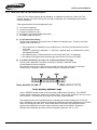
5.1 Replacing the Probe Filter
Air (and measured gas) is drawn in through the probe at a rate of about 4.5 ml/s. Any dust drawn in by the air is
removed by the probe filter. When the material removed begins to clog the filter sufficiently that a condition in which
the flow drops to around 1/4 that rate continues longer than 30 seconds, " AIR FLOW " will appear on the display.
(Note that " AIR FLOW " may also be displayed for other reasons.)
If "AIR FLOW" is displayed, first make a visual check of the probe filter. If it is dirty, replace it the filter has directivity.
Attach it with its smooth surface on the side of the tube for introducing gas.
If "AIR FLOW" is still displayed even after you have replaced the filter, the cause may be one of the following.
•
•
•
Suction pump malfunction
Problem in the instrument internal tubing
Flow sensor malfunction
See Chapter 6 for instructions on how to check for these problems, and what action to take.
Instruction 3015-0216
43
H-25C Instruction Manual
5.2 Replacing the Activated Charcoal Filter
The measured gas going to the sensor is split into two a by a manifold, one stream being introduced with no
treatment, the other being introduced after being passed through the activated charcoal filter to convert it to clean,
pure air. If the activated charcoal filter is unable to purify the measured gas, the result will be the same as if extra
untreated measured gas were flowing into the sensor, giving a too-high indication for the leak rate.
Since allowing extra untreated gas to flow into the sensor will shorten the sensor life, in addition to causing
measurement errors, you must replace the activated charcoal filter before it loses its effectiveness at conversion.
In general, if you are using the H-25C seven hours a day, an activated charcoal filter can be used for 30 to 60
days. We recommend that you schedule periodic replacements using these numbers as guidelines. If the
measurement check described in Subsection 4.2.6 reveals error in the measurement, you should replace the filter
promptly.
Note : The service life of the activated carbon filter may be greatly reduced if a large amount of freon gas is
contained in the atmosphere.
The replacement procedure is as follows:
(1)
Disconnect the tube from the tube joint attached to the activated-charcoal filter ( case cap ).
(2)
Remove the activated-charcoal filter (filter case) from its mounting seat. (It is screwed into the seat, and must
be turned counterclockwise to remove it.)
(3)
Turn the case cover counterclockwise to remove the cover.
(4)
Remove the used filter pack from the case.
(5)
Take out a new filter pack from its bag.
Instruction 3015-0216
44
H-25C Instruction Manual
(6)
Install the filter in the case as follows:
(a) First, squeeze the filter to fit it into the circular case. (see figure 5.3)
(b) Insert the filter into the case. Holding the seam 1) of the filter, fold both sides 2) and C3 into the case,
then push them down into the case. (see figure 5.4)
(c) Push down the whole filter until it is lower than the top edge of the case.
(d) Replace the cover so the open end of the tube (beneath the cover) touches the
center-portion, but must not touch seam or penetrate the filter bag. (see figure 5.5)
(e) Tighten the cover to complete the filter replacement.
(7)
Screw the activated-charcoal filter (filter case) to its mounting seat.
(8)
Insert the tube into the tube joint attached to the case cap.
Instruction 3015-0216
45
H-25C Instruction Manual
5.3
Refilling the Tank With Freon
This maintenance operation is applicable only if the instrument has the auto calibration option. The R134a
held in the tank for calibration use is consumed at a rate of 10 x 10-5 std. ml/s. When the calibration gas
secondary pressure indication on the bar graph drops to the 1 00% point ( 98 kPa I 1.0 kgf/CM2 1), refill the
tank with R - 134a by the following procedure. For filling, a dedicated liquid-freon-filling jig (part number :
E708OFZ ) is necessary.
Note: Part number : The item with part number E70BOFZ is an accessory attached to the LS - 20B leak
standard, which contains auxiliaries other than the freon filling jig.
(1)
Remove the instrument cover.
(2)
Fully close the valve on the tank. Turn the handle on the tank top fully clockwise close.
(3)
Close the regulator valve by pulling up on the knob and turning counterclockwise.
(4)
Loosen the two tank mounting screws, and remove the tank, being very careful not to lose the 0-ring at
the tank's gas outlet port.
In the next step, you will begin the filling task. Since a large amount of freon gas will leak out during
this process, you should do the work in a location well removed from the leak inspection area.
(5)
Open the tank valve (turning the handle) to discharge the remaining R - 134a (gas).
(6)
Weigh the tank before filling, so that you will be able to find out how much it has been filled.
(7)
Mount the freon filler fitting on a service cylinder containing R - 134a. Before you do this, first make
sure that the filler-fitting valve is closed. Then set the fitting on the cylinder and make sure that the
three hooks on the clamp securely engage the cylinder top cover. Next, turn the valve body clockwise
to pierce through into the cylinder.
(8)
Connect the service cylinder and tank using the coupler on the filler fitting. To do this, first remove the
plug from the tank, and attach the coupler in its place. Screw the coupler on and tighten lightly with a
wrench. Next, Connect the valve that you mounted on the service cylinder to the coupler. Screw them
together by hand.
(9)
Turn the service cylinder upside down, and allow the tank to fill with liquid R - 134a. First, fully open the
valve attached to the service cylinder. Next, very slightly open the valve on the tank (turning the
Instruction 3015-0216
46
H-25C Instruction Manual
handle), allowing the air to be expelled as the liquid R - 134a enters. After a short while some misty
liquid R 134a will begin to spray out in a mist.
Wait about 10 seconds after the mist begins spraying out, and then close the tank valve. Also be sure
to close the service cylinder valve. Then, waiting about one minute between repetitions, very slightly
open the tank valve again for about 5.seconds, and repeat this action two or three times.
(10) Remove the coupler from the tank, and remount the plug as it was originally. As soon as the coupler is
removed, R - 134a gas in the tank blows off. Quickly perform the work. Tighten the plug to a torque of
about 3 N-m f 30 kgf-cm 1.
(11) Verify that enough R - 134a liquid (25 to 30 g) went into the tank. Weigh the tank, and compare the
new weight to the weight measured in " (6) ". Also examine the tank to make sure that there is no leak
from the plug area.
(12) Remount the tank in the instrument main unit. Check to make sure that the gas outlet port 0-ring is in
place, and firmly tighten two mounting screws.
(13) Adjust the calibration gas secondary pressure following the procedure given in Section 2.6.
Note that proper calibration will be impossible if any air is left in the tubing. After adjustment, loosen the
gas bleed plug for about three seconds; repeat @s action two or three time.
5.4
Replacing the Sensor
Since the sensor sensitivity will gradually deteriorate over time, you will need to adjust the " HEATER "
variable resistor whenever the sensor sensitivity displayed during calibration goes outside the permissible
range (60 to 150% on the bar graph). When the " HEATER " variable resistor shaft will not rotate any farther
in the clockwise direction, the sensor has reached the end of its useful life.
Note: Our guideline for sensor life is 900 to 1000 hours of operation. However, the life is sometimes shorter,
depending on the concentration of the reacting gases (freon, etc.) and how long they are drawn in.
When the sensor reaches the end of its life, you must replace it with a new sensor. The replacement
procedure is as follows:
(1)
Turn the power switch OFF, and wait until the sensor has cooled down (about ten minutes).
(2)
Remove the instrument main unit cover and the sensor chamber cover. Then remove the sensor, by
first disconnecting the tubing connector on its top and then unplugging it from its socket.
(3)
Plug the new sensor into the socket. Then reconnect the tubing connector to the sensor. After thus
installing the sensor, replace the main unit cover and the sensor chamber cover.
Instruction 3015-0216
47
H-25C Instruction Manual
(4)
Return the " HEATER " variable resistor adjustment shaft to its starting position. First, turn it
counterclockwise until you reach the limit of rotation, then turn it back clockwise 12 full turns.
(5) Adjust the sensor sensitivity so that the bar graph indicates a value between 80 and 110% (see
Subsection 3.1.3).
5.5
Replacing the Disc Filter
If liquid is sucked in by mistake or the gas suction too weak even after replacing the
probe filter, check the disc filter in the instrument ( see page 6 - 2 , tiger 6.1 any liquid or contamination,
replace the disc filter.
Note:
If any liquid is sucked in, dry the inner tube before replacing the filter.
Note the following when replacing the filter:
• Turn the power switch off.
• Since the disc filter distinguishes the inflow direction from the outflow direction, mount it correctly. The
shape of the filter case on the gas-inflow side is simpler than on the gas-outflow side.
5.6
Replacing the Fuse
If the instrument will not operate at all when you apply power, check the fuse. The fuse is mounted inside
the power cable connector on the main unit rear. You will also find a spare fuse stored in the connector.
These fuses are attached to a cover, which also serves as the fuse holder; use a flat-blade screwdriver to
open this cover.
If the fuse connected in the circuit is open, replace it with the spare fuse.
[Fuse Ratings] - 3.15A, 250V, fast-blow, miniature type (Bacharach part number: K9346JD)
Instruction 3015-0216
48
H-25C Instruction Manual
6. TROUBLESHOOTING
This chapter explains how to identify and take corrective action for certain types of malfunctions.
If you find that the malfunction is due to actual failure of the instrument hardware, contact your Bacharach
representative for service. Such repairs can be made only by an authorized Bacharach service center.
6.1 Improper Use Leading to Hardware Failure
Improper use that can cause hardware failures must be absolutely avoided. Subsections 6.1.1 and 6.1.2 describe
two types of improper use against which you must take particular care.
6.1.1
Never connect 240 V power when the supply voltage selector switch is set to a 100 V range
Note: The H-25C is offered in three versions : 100 / 115 V, 110 / 220 V, 120 / 240 V power.
Connecting 240 V power to an H-25C set up for a voltage in the 100 V range will burn out the
transformer. (In some cases, only a blown fuse may result.)
If you accidentally make this mistake, check the fuse first. If the instrument does not operate after you
replace the fuse, repair will be required.
6.1.2
Never allow liquid to be sucked in
The tubing system inside the instrument includes a manifold designed to precisely divide the measured
gas flow. If you allow liquid to be sucked into the instrument, contaminants will be deposited on the
manifold surfaces, changing the division ratio so that accurate measurement will become impossible.
If there are any liquids in use in the area where the instrument is placed, or it is possible that there may
be condensation on the equipment being inspected, you must take great care in the handling of the
probe.
If any liquid is accidentally sucked in, turn the power switch OFF immediately. Then do the following:
•
If liquid did not get into the instrument's internal tubing. If the amount drawn in was small, and you
noticed it immediately, then the liquid may not have gone past the probe filter. Check the probe filter.
If the gas outlet side of the probe is somewhat wet, replace the filter after drying the tip of the probe
(the tube for introducing gas for the S-type probe and the flexible probe for the L-type probe ). If the
liquid penetrated to the cable section, remove the filter and flow air through from the connector end to
dry the inside of the tubing.
•
If liquid did get into the instrument's internal tubing In most cases where liquid has been continuously
drawn in for some time, the liquid will have entered the instrument's internal tubing system. Inspect
the disc filter in the instrument, and if there is any leakage, the instrument must be repaired by
Bacharach.
Instruction 3015-0216
49
H-25C Instruction Manual
6.2 Possible Causes of Malfunctions, and What to Do If They Occur
Table 6.1 lists the most common malfunctions (symptoms). Subsections 6.2.1 through 6.2.10 show what can
cause these symptoms, and what to do if they occur.
When it Happened
When power applied
During measurement
During calibration
6.2.1
Symptom
Doesn’t operate at all
“CAL FAIL” on steady during countdown
Does not detect leaks
Measured value is too low
Measured value is too high
“AIR FLOW’ on steady
Frequent calibration requests
Very short sensor life
“CAL FAIL” on steady
Cal gas in tank used up to quickly
Won’t calibrate to proper value
What to Read
See Subsection 6.2.1
See Subsection 6.2.8
See Subsection 6.2.2
See Subsection 6.2.3
See Subsection 6.2.4
See Subsection 6.2.5
See Subsection 6.2.6
See Subsection 6.2.7
See Subsection 6.2.8
See Subsection 6.2.9
See Subsection 6.2.10
Does Not Operate at All
The three most likely causes are
(1) Blown Fuse - After making sure that power is actually being supplied, check the fuse. (See Section
5.6)
Note: If fuses are blowing frequently, have the instrument inspected by Bacharach.
(2) Broken Wire in Power Cable Replace with good cable.
(3) Transformer Burnt Out Return to Bacharach for repair (component replacement).
6.2.2
Does Not Detect Leaks
The four most likely causes are:
(1) Search mode trigger point value is too high. Increase the search mode sensitivity multiplier. (See
Subsection 2.2.9)
(2) Air is leaking into the probe through the probe seal (O-ring or gasket) Check whether or not the nut
(rod) is loose. For the L-type probe, check whether or not the 0 - ring is in place.
(3) Tubing not connected to sensor.
(2) Sensor failure. Replace with good sensor.
Note: If the sensor is not heating up, return the instrument to Bacharach for repair.
6.2.3
Measured Value is Too Low
The three most likely causes are:
(1) Not properly calibrated. Re-calibrate.
Instruction 3015-0216
50
H-25C Instruction Manual
(2) Air is leaking into the probe through the probe seal ( 0 -ring or gasket Check whether or not the nut
(rod) is loose. For the L-type probe, check whether or not the 0 -ring is in place.
(3) Contamination deposited on manifold internal flow path surfaces. Return to Bacharach for repair
(component replacement).
6.2.4
Measured Value is Too High
The three most likely causes are:
(1) Not properly calibrated. Re-calibrate.
(2) Activated charcoal filter has reached end of life. Replace with new activated charcoal filter.
(3) Tubing not connected to activated charcoal filter.
6.2.5
“AIR FLOW" on Steady
The most likely five causes are
(1) Probe filter clogged. Replace with new filter.
(2) Clogged disk filter. Replace with new filter.
(3) Pump not working, or performing poorly. Replace with good pump.
Note - No adjustment required after replacement.
(4) Manifold internal flow path clogged. Return to Bacharach for repair (component replacement).
(5) Flow sensor failure Return to Bacharach for repair (component replacement).
6.2.6
Frequent Calibration Requests
The most likely two causes are:
(1) Instrument is reacting to some gas in the surrounding air. Improve the operating environment.
Decrease the search mode sensitivity (sensitivity multiplier). (See Subsection 2.2.9)
(2) Calibration request interval time setting is too short. Set longer interval. (See Subsection 2.2.8)
6.2.7
Very Short Sensor Life
The most likely three causes are:
(1) Sensor sensitivity set too high. Lower sensor sensitivity. (See Subsection 3.1.3)
(2) Activated charcoal filter not drawing in gas. Replace with new activated charcoal filter. (activatedcharcoal pack)
(3) Liquid has been sucked into the instrument.
6.2.8
"CAL FAIL" on Steady
The most likely five causes are:
Instruction 3015-0216
51
H-25C Instruction Manual
[If occurring during countdown at power-on:]
Note: Verify that the steady-on or flashing condition recurs.
(1) EEPROM failure. Return to Bacharach for repair (component replacement, adjustment).
[If occurring during calibration]
(2) Sensor sensitivity outside of permissible range. Adjust sensor sensitivity (See Subsection 3.1.3)
(3) Sensor has reached end of life. Replace with new sensor. (See Section 5-4)
(4) Calibration gas (liquid) in tank completely used up. Refill tank with liquid R - 134a. (See Section 5.3)
(5) Capillary clogged. Return to Bacharach for repair (component replacement, adjustment).
6.2.9
Liquid R134a in Tank Used Up Too Quickly
The most likely two causes are:
(1) Leakage from gas bleed plug (at capillary receiver section). Check first whether plug is loose. If not,
replace 0-ring.
(2) Leakage from tank seal (gas outlet port 0-ring, or plug area). Replace bad component. (Replace
according to procedures in Section 5.3).
6.2.10 Won't Calibrate to Proper Value
The most likely four causes are: [If during auto calibration]
(1) Fan not working. Replace fan.
(2) Contamination deposited inside capillary, preventing calibration gas from flowing at specified rate.
Return to Bacharach for repair (component replacement, adjustment).
(3) Air left inside tubing (immediately after refilling tank with R - 134a). Loosen gas bleed plug and let air
escape.
[If during manual calibration]
(4) Value entered in calibration differed from leak standard leak rate. Repeat calibration, entering the
correct value.
Instruction 3015-0216
52
H-25C Instruction Manual
[Reference] Facilities for Ridding the Atmosphere of Unwanted
Gases Where Leakage Inspections Are Made
Sensors in the H-25C Halogen Leak Detector sense exhaust gases from automobiles and volatilized gases from organic
solvents, floor cleaning agents, and -paint as well as halogen gases including freon. Thus, if any of these gases are in
the surrounding atmosphere of locations when inspections for leakage are made, the following two problems may occur.
1. The service life of sensors and activated charcoal filters is shortened.
2. It becomes difficult to find and measure slight leaks.
If these problems are anticipated, it is recommended that the facilities described below be provided.
[Example 1 of Proper Facility]
Reference Figure 1 shows an example of a facility that helps extend the service life of sensors and activated
charcoal filters. As shown in the figure, providing a facility with clean air that can be auctioned through the sensor
probe when preparing for measurement greatly reduces the time needed to suction the unwanted gases. This
not only prolongs the service life of sensors and activated-charcoal filters, but also makes accurate calibration
(based on clean air as the background) possible in locations where inspections for leakage are made.
In addition, provide such a facility by taking into account the following requirements:
(1) Do not allow moisture to collect on the inside of the delivery tube as droplets.
(2) Make sure the e is securely fastened (cannot drop).
Instruction 3015-0216
53
H-25C Instruction Manual
[Example of Facility 2]
Reference Figure 2 shows an example of facility for efficiently implementing leakage inspection.
This facility is also provided with countermeasures to prolong the service life of sensors and activated charcoal
filters.
If the facility to be provided is similar to that shown in Reference Figure 2, take the following requirements into
consideration.
(1)
The air flow inside the facility cannot cause negative pressure.
(2)
Air is fed to the inspection area in an evened-out flow.
(3)
The inspection area cannot be so seriously affected by the temperature and humidity of the outside air.
Instruction 3015-0216
54
H-25C Instruction Manual
Customer Maintenance Parts List
Item
1
2
3
4
5
6
7
8
9
10
11
12
Part No.
3015-1113
3015-4181
3015-1134
3015-2753
3015-1209
3015-1310
3015-2363
3015-2398
3015-2418
3015-1630
3015-0807
3015-2552
3015-2556
3015-2560
Instruction 3015-0216
Qty.
1
1
1
2
1
1
1
1
1
1
1
1
Description
Pump Assembly
Regulator Assembly
Regulator
O-Ring
Flow Sensor Assembly
Fun Assembly
Activated-charcoal Filter
Sheet (filter)
Activated-charcoal Pack (5 pcs)
Fuse (3.15 A 250V)
Sensor
Transformer Assembly
(for 100/115 V power)
(for 120/240V power)
(for 110/220V power)
Item
13
14
15
16
17
55
Part No.
3015-2476
3015-1092
3015-1182
3015-2757
3015-1855
3015-1860
3015-2213
3015-2150
3015-2218
Qty.
1
1
1
1
Description
Filter
Speaker
Screw
O-Ring
Probe
S-type, 1.8 m
S-type, 4.5 m
L-type, 1.8 m
L-type, 4.5 m
L-type, 7.5 m
H-25C Instruction Manual
Item
1
2
3
4
5
6
7
8
Instruction 3015-0216
Part No.
3015-1200
3015-2668
3015-2672
3015-2676
3015-0947
3015-1545
3015-2096
3015-2102
3015-2108
3015-2114
3015-1194
Qty.
1
1
1
1
1
1
1
1
Description
Tank Assembly w/freon
O-Ring
O-Ring
O-Ring
O-Ring
Printed-circuit Assembly
Printed-circuit Assembly
(For 100/115V power)
(For 100/115V power. With output
signal)
(For 120/240V or 110/220 V power)
(For 120/240V or 110/220V power.
With output signal)
Pressure Sensor
56
H-25C Instruction Manual
Sales / Service Centers
U.S.A.
Bacharach Sales/Service Center - California
7281 Garden Grove Blvd., Suite H
Garden Grove, CA 92841
Tel.: 714-895-0050
Fax: 714-895-7950
E-mail: [email protected]
CANADA
Bacharach of Canada Sales/Service Center
250 Shields Court, Unit #3
Markham, Ontario L3R 9W7 CANADA
Tel.: 905-470-8985
Fax: 905-470-8963
Toll Free in Canada: 800-328-5217
E-mail: [email protected]
Bacharach Sales/Service Center - Georgia
2 Dart Road
Newnan, GA 30265-1094
Tel.: 678-423-2481
Fax: 678-423-2479
E-mail: [email protected]
MEXICO
Bacharach de México S.de R. L. de C.V.
Sales/Service Center
Playa Regatas No. 473 Tercer Piso
Col. Militar Marte
Delegación Iztacalco, 08830
México D.F. México
Tels.: +52-55-56-34-77-40 / 41
Fax:
+52-55-56-34-77-38
E-mail: [email protected]
Bacharach Sales/Service Center - Indiana
8618 Louisiana Place
Merrillville, IN 46410
Tel.: 219-736-6178
Fax: 219-736-6269
E-mail: [email protected]
BRAZIL
Bacharach International
Rua das Laranjeiras, 498/602
Rio de Janeiro, RJ 22.240-002, Brazil
Phone : +55-21-2556-1156
Fax : +55-21-2557-9937
Cell. : +55-21-9976-5088
E-mail : [email protected]
Bacharach Sales/Service Center – New Jersey
7300 Industrial Park
Rte. 130, Bldg. 22
Pennsauken, NJ 08110
Tel.: 856-665-6176
Fax: 856-665-6661
E-mail: [email protected]
Bacharach Sales/Service Center - Pennsylvania
621 Hunt Valley Circle
New Kensington, PA 15068-7074
Tel.: 724-334-5051
Fax: 724-334-5723
E-mail: [email protected]
EUROPE
Bacharach Instruments – European Headquarters
Sovereign House
Queensway, Leamington Spa
Warwickshire, England CV31 3JR
Tel.: +44 (0) 1926 338111
Fax: +44 (0) 1926 338110
E-mail: [email protected]
Website: www.bacharach-europe.com
Bacharach Sales/Service Center - Texas
5151 Mitchelldale, B-4
Houston, TX 77092
Tel.: 713-683-8141
Fax: 713-683-9437
E-mail: [email protected]
Bacharach Instruments Sales/Service Center Denmark
P.O. Box 44
39 Lindegade
DK 6070 Christiansfeld, Denmark
Tel.: (+45) 74 56 31 71
Fax: (+45) 74 56 31 78
E-mail: [email protected]
Instruction 3015-0216
57
H-25C Instruction Manual
Notes:
Instruction 3015-0216
58
World Headquarters
621 Hunt Valley Circle, New Kensington, PA 15068
Ph: 724-334-5000 • Fax: 724-334-5001 • Toll Free: 1-800-736-4666
Website: www.bacharach-inc.com • E-mail: [email protected]
Printed in U.S.A.