1
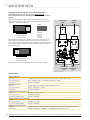
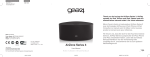
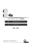
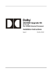
AES3 – S/P-DIF DIGITAL AUDIO FORMAT
AND SAMPLING RATE CONVERTER
SAFETY INSTRUCTIONS
General instructions
To reduce the risk of fire or electrical shock, do not expose this appliance to rain or moisture, direct
sunlight or excessive heat from sources such as radiators or spotlights. No user serviceable parts are inside. Repair and maintenance must be carried out by qualified personnel authorized by MUTEC GmbH!
The unit has been designed for operation in a standard domestic environment. Do NOT expose the unit
and its accessories to rain, moisture, direct sunlight or excessive heat produced by such heat sources as
radiators or spotlights! The free flow of air inside and around the unit must always be ensured.
Initial operation
Prior to the initial operation of the unit, the appliance, its accessories and packaging must be
inspected for any signs of physical damage that may have occurred during transit. If the unit has
been damaged mechanically or if liquids have been spilled inside the enclosure, the appliance may
not be connected to the mains or must be disconnected from the mains immediately! If the unit is
damaged, please do NOT return it to MUTEC GmbH, but notify your dealer and the shipping company immediately, otherwise claims for damage or replacement may not be granted.
If the device is left in a low-temperature environment for a long time and then is moved to a roomtemperature environment, condensation may occur on the inside and the exterior. To avoid shortcircuits and flashovers, be sure to wait one or two hours before putting the device into operation.
Power supply
The device contains a self-adapting wide-range power supply supporting the majority of global standard line voltages within a range of 90…250 V, with no need for making adjustments. Make sure that
your line-voltage source provides a supply voltage within the specified range. In addition, make sure
that the device is properly grounded via the local electric installation.
Please use the enclosed power cord (see packaging) to connect the unit to the mains. Switch the
unit off before you attempt to connect it to the mains. Connect the power cord to the unit, then
to a standard 3-pin mains outlet. To draw the power cord, never pull on the cable but on the mains
plug!
C A U T I O N
R I S K
O F
ELECTRICAL SHOCK!
!
This symbol, a flash of lightning inside a triangle, alerts
you to the presence of uninsulated dangerous voltage
inside the enclosure - voltage that may be sufficient to
constitute a risk of shock.
!
This symbol, an exclamation mark inside a triangle,
alerts you to important operating or safety instructions
in this manual.
Declaration of Conformity
We herewith confirm that the product complies with the European
Commission’s standards on electromagnetic compatibility.
Interference emission:
Resistance to interference:
EN 50081-1, 1992
EN 50082-1, 1992
Presupposed as operation condition is that all clock outputs are connected with high-quality and good shielded BNC 75 ohms cable.
The unit must be grounded during operation!
For information on the power-inlet wiring, refer to the »Wiring of connectors« section in the
appendix. Disconnect the device from the mains when not using it for an extended period!
WARRANTY REGULATIONS
§1 Warranty
MUTEC GmbH warrants the flawless performance of this product to the original buyer for a period of two (2) years from the date of purchase. If any failure occurs within
the specified warranty period that is caused by defects in material and/or workmanship, MUTEC GmbH shall either repair or replace the product free of charge within 90
days. The purchaser is not entitled to claim an inspection of the device free of charge during the warranty period. If the warranty claim proves to be justified, the product
will be returned freight prepaid by MUTEC GmbH within Germany. Outside Germany, the product will be returned with the additional international freight charges payable
by the customer. Warranty claims other than those indicated above are expressly excluded.
§2 Warranty transferability
This warranty is extended exclusively to the original buyer who bought the product from a MUTEC GmbH specialized dealer or distributor, and is not transferable to anyone
who may subsequently purchase this product. No other person (retail dealer, distributor, etc.) shall be entitled to give any warranty promise on behalf of MUTEC GmbH.
§3 Waranty regulations
The return of the completed registration card, or online registration on one of the websites specified below, is a condition of warranty. Failing to register the device before
returning it for repair will void the extended warranty.
The serial number on the returned device must match the one stated on the registration card or entered during online registration. Otherwise, the device will be
returned to the sender at the sender’s expense.
Any returned device must be accompanied by a detailed error description and a copy of the original sales receipt issued by a MUTEC dealer or distributor.
The device must be returned free of shipping expenses and in the original package, if possible; otherwise, the sender has to provide comparably protective packaging.
The sender is fully responsible for any damage or loss of the product when shipping it to MUTEC GmbH.
§4 Limitation of warranty
Damages caused by the following conditions are not covered by this warranty:
Damages caused by every kind of normal wear and tear (e.g. displays, LEDs, potentiometers, faders, switches, buttons, connecting elements, printed labels, cover
glasses, cover prints, and similar parts).
Functional failure of the product caused by improper installation (please observe CMOS components handling instructions!), neglect or misuse of
the product, e.g. failure to operate the unit in compliance with the instructions given in the user or service manuals.
Damage caused by any form of external mechanical impact or modification.
Damage caused by the user’s failure to connect and operate the unit in compliance with local safety regulations.
Damage caused by force majeure (fire, explosion, flood, lightning, war, vandalism, etc.).
Consequential damages or defects in products from other manufacturers as well as any costs resulting from a loss of production.
Repairs carried out by personnel which is not authorized from MUTEC GmbH will void the warranty. Adaptations and modifications to the device made with regard to
national, technical, or safety regulations in a country or of the customer do not constitute a warranty claim and should be set with MUTEC GmbH in advance.
§5 Repairs
To obtain warranty service, the buyer must call or write to MUTEC GmbH before returning the unit. All inquiries must be accompanied by a description of the problem and
the original buyer’s invoice. Devices shipped to MUTEC GmbH for repair without prior notice will be returned to the sender at the sender’s expense. In case of a functional
failure please contact:
MUTEC Gesellschaft fuer Systementwicklung und Komponentenvertrieb mbH
Siekeweg 6/8 • 12309 Berlin • Germany • Fon 030-746880-0 • Fax 030-746880-99 • [email protected] • www.MUTEC-net.de
JET and Jitter Elimination Technology are trademarks of TC Applied Technologies Ltd. The JET technology is used under sublicense from TC Applied Technologies Ltd., and is the intellectual property of
Sonopsis Ltd. Applicable patents include WO2004088845.
MUTEC GmbH assumes no liability for any incorrect information given in this manual. Please note that
all software/hardware product names are registered trademarks of their respective owners. No part of
this manual may be reproduced, copied or converted to a machine-readable form or electronical media
without a written permission of MUTEC GmbH. We reserve the right to change or improve our products
without prior notice. © MUTEC GmbH 2010
CONTENT
INTRODUCTION
General Function Description . . . . . . . . . . . . . . . . . 7
MC-6 Features . . . . . . . . . . . . . . . . . . . . . . . . . 7
MC-6 Applications . . . . . . . . . . . . . . . . . . . . . . . 7
Peripheral MUTEC Products . . . . . . . . . . . . . . . . . . 8
CONTROL ELEMENTS AND TERMINALS
MC-6 Front Panel . . . . . . . . . . . . . . . . . . . . . . . . 9
MC-6 Rear Panel . . . . . . . . . . . . . . . . . . . . . . . . 9
INSTALLATION
Content of the Box . . . . . . . . . . . . . . . . . . . . . . . 11
Placing the device . . . . . . . . . . . . . . . . . . . . . . . 11
Wiring the AES/EBU, AES/EBUid and S/P-DIF Interfaces . . . 11
Wiring the Word Clock Interfaces . . . . . . . . . . . . . . . 11
GENERAL OPERATION
Selecting Function Menus and setting Functions . . . . . . 13
Steps of Operation . . . . . . . . . . . . . . . . . . . . . . . 13
OPERATING THE MC-6
MODE / AUDIO IN + REFERENCE Menus . . . . . . . . . . . . 15
General Operation Procedure . . . . . . . . . . . . . . . . . 15
Unidirectional Format Conversion from:
AES3 to AES3id, S/P-DIF optical + coaxial, AES3 . . . . . . . 16
Unidirectional Format Conversion from:
AES3id to AES3, S/P-DIF optical + coaxial, AES3id . . . . . . 16
Unidirectional Format Conversion from:
S/P-DIF optical to AES3, AES3id, S/P-DIF coaxial + optical . . 16
Unidirectional Format Conversion from:
S/P-DIF coaxial to AES3, AES3id, S/P-DIF optical + coaxial . . 17
Unidirectional Format with Sampling Rate Conversion from:
AES3 to AES3id, S/P-DIF optical + coaxial, AES3 . . . . . . . 17
Unidirectional Format with Sampling Rate Conversion from:
AES3id to AES3, S/P-DIF optical + coaxial, AES3id . . . . . . 18
Unidirectional Format with Sampling Rate Conversion from:
S/P-DIF optical to AES3, AES3id, S/P-DIF coaxial + optical . . 18
Unidirectional Format with Sampling Rate Conversion from:
S/P-DIF coaxial to AES3, AES3id, S/P-DIF optical + coaxial . . 18
Bidirectional Format Conversion between
AES3 and AES3id . . . . . . . . . . . . . . . . . . . . . . . . 19
Bidirectional Format Conversion between
AES3 and S/P-DIF optical . . . . . . . . . . . . . . . . . . . . 19
Bidirectional Format Conversion between
AES3 and S/P-DIF coaxial . . . . . . . . . . . . . . . . . . . . 19
Bidirectional Format Conversion between
AES3id and S/P-DIF optical . . . . . . . . . . . . . . . . . . . 20
Bidirectional Format Conversion between
AES3id and S/P-DIF coaxial . . . . . . . . . . . . . . . . . . 20
Bidirectional Format Conversion between
S/P-DIF optical and S/P-DIF optical . . . . . . . . . . . . . . 20
Bidirectional Format and Sampling Rate Conversion between
AES3 and AES3id . . . . . . . . . . . . . . . . . . . . . . . . 20
Bidirectional Format and Sampling Rate Conversion between
AES3 and S/P-DIF optical . . . . . . . . . . . . . . . . . . . . 21
Bidirectional Format and Sampling Rate Conversion between
AES3 and S/P-DIF coaxial . . . . . . . . . . . . . . . . . . . . 21
Bidirectional Format and Sampling Rate Conversion between
AES3id and S/P-DIF optical . . . . . . . . . . . . . . . . . . . 21
Bidirectional Format and Sampling Rate Conversion between
AES3id and S/P-DIF coaxial . . . . . . . . . . . . . . . . . . 22
Bidirectional Format and Sampling Rate Conversion between
S/P-DIF optical and S/P-DIF coaxial . . . . . . . . . . . . . . 22
X-SRC Mode between
AES3 and AES3id . . . . . . . . . . . . . . . . . . . . . . . . 22
X-SRC Mode between
AES3 and S/P-DIF optical . . . . . . . . . . . . . . . . . . . . 23
X-SRC Mode between
AES3 and S/P-DIF coaxial . . . . . . . . . . . . . . . . . . . . 23
X-SRC Mode between
AES3id and S/P-DIF optical . . . . . . . . . . . . . . . . . . . 24
X-SRC Mode between
AES3id and S/P-DIF coaxial . . . . . . . . . . . . . . . . . . 24
X-SRC Mode between
S/P-DIF optical and S/P-DIF coaxial . . . . . . . . . . . . . . 24
STATUS . . . . . . . . . . . . . . . . . . . . . . . . . . . . . 25
REF CLOCK IN . . . . . . . . . . . . . . . . . . . . . . . . . . 25
APPENDIX
Pin Assignment of the Connectors . . . . . . . . . . . . . . 27
Switching-off the Termination of the Word Clock Input . . . 28
Technical Data . . . . . . . . . . . . . . . . . . . . . . . . . 28
! INTRODUCTION
Thank you very much for purchasing MC-6, Digital Audio Format and Sampling Rate Converter, from MUTEC!
General Function Description
The MC-6 is an extremely flexible, high-performance digital audio format
and sampling rate converter for AES3, AES3id and S/P-DIF. All digital audio
signals can be processed with sampling rates up to 192.0kHz, whereas
unidirectional and bidirectional conversion modes are available. Based on
latest FPGA designs, the MC-6 achieves levels of performance regarding
its signal quality, unique flexibility, clocking features and the 4 channel
sampling rate conversion engine (SRC), which are outstanding in today’s
industry!
Various operation modes enable the use of the MC-6 in many studio setups. Generally, incoming digital audio signals are converted to all three
audio formats simultaneously, with or without SRC functionality. The SRC
engine can be locked to Word Clock, AES11 and any digital audio input in
both, unidirectional and bidirectional operation modes.
Furthermore, the MC-6 offers an internal, Ultra low-jitter clock base with
outstanding accuracy to which the SRCs can be locked to, if no external
reference is available. This enables to run the MC-6 in set-ups where no
separate master clock system is available. Furthermore, in this operation
mode the MC-6‘s Word Clock output supplies an Ultra low-jitter reference
clock signal which is of same high accuracy as the internal clock basis. This
can be used e.g. as master clock reference for the whole studio.
The grey boxes contain supplementary
informationen for the corresponding
sections in the text columns. The content of
the individual box refers to the description
in the text column beside the box.
Boxes which contain a triangle with
an exclamation mark inside should
be read carefully! These include
additional information which are of major
importance for the functional descriptions
in the text column.
!
This all makes MC-6 for sure a unique and the most flexible digital audio
format converter in a 9.5“ case currently available in the market!
MC-6 Features
AES/EBU, AES/EBUid and S/P-DIF interfaces in one box.
Bidirectional format and sampling rate conversions
from 32.0 kHz to 192.0 kHz.
Converts standalone and bidirectionally with different sampling rates: X-SRC
Signal improvement through low-jitter clock recovery.
AES11, Grade 1, internal reference clock (0.5ppm).
Word Clock output can be used as master clock reference.
Runs standalone without needing an external clock source.
4 channel SRC engine for bidirectional conversions.
Extremely flexible synchronization options.
Continuous signal supply in absence of the reference audio or clock signal.
Separate AES11 reference clock input.
Simultaneous conversions to all output formats.
Easy configurable.
User‘s settings will be stored after switching-off.
Rack space saving 1/2 19“ housing allowing for mounting two devices
in one rack unit.
Built-in international power supply.
MC-6 Applications
Interconnection of consumer and professional digital audio devices.
AES3, AES3id and S/P-DIF format and sampling rate conversions.
Integration of non-synchronizable devices into digital studio
environments.
Clock recovery and digital audio signal regeneration.
Realtime bidirectional signal transfer between send/returns of digital
mixing consoles and effect processors.
Unidirectional or bidirectional interconnection of computer-based sound
cards with professional digital audio equipment.
Usable within small studio set-ups up to broadcast installations.
7
!"!
Peripheral MUTEC Products
Reference Clocks and Master Clocks for Synchronization:
iCLOCK + iCLOCKdp
iCLOCK and iCLOCKdp are synchronizable, high-precision clock
generators which are designed to be the reference in digital audio and
video studios as well as broadcast and television stations. For further
details please visit:
www.iCLOCK-NET.de
MC-3
The MC-3 SMART CLOCK is an universal digital audio master clock
generator. The unit provides different high-stable and Ultra low-jitter
clock signals for synchronization of various digital audio devices.
MC-3.1
The MC-3.1 SMART CLOCK SD is an universal digital audio and SD video
sync master clock generator. The unit provides different high-stable
clock signals for simultaneous synchronization of digital audio and SD
video devices.
MC-3.2
The MC-3.2 SMART CLOCK HD is an universal digital audio and SD/HD
video sync master clock generator. The unit provides different highstable clock signals for simultaneous synchronization of digital audio
and SD/HD video devices.
MC-2
The MC-2 is a high-performance digital audio and reference clock signal
distribution amplifier and format converter for AES3/11 and AES3/11id
signals.
MC-7
The MC-7 is a flexible, high-performance 8-channel Word Clock distribution amplifier and audio clock converter.
Cables for Digital Audio:
Optical cables in different lenghts from 0.5 m to 20 m for S/P-DIF and
ADATTM transfers.
For all peripheral products please have a look on our website:
www.MUTEC-NET.de !
8 ! CONTROL ELEMENTS AND TERMINALS
MC-6 Front Panel
1
2
3
4
4
5
6
7
1 POWER
This red LED lights up when the unit is switched on with the rear panel
POWER switch.
2 MENU
The push-button selects one of the available function menus.
Refer to the OPERATIONS chapter for more
information.
3 SELECT
Use this push-button to select a function within a specific function menu.
4 MODE + AUDIO IN
This function menu allows to adjust all available conversion modes (LED
line »MODE«) in combination with the corresponding digital audio formats
(LED line »AUDIO IN«) .
5 REFERENCE
This function menu allows to select the master clock reference for synchronization of the format conversion section as well as the SRCs.
6 STATUS
This menu indicates various signal statuses of the incoming master clock
reference signal and the digital audio signal. For details see page 25.
7 REF CLOCK IN
This menu indicates the clock rates of the incoming digital audio signal or
of the master clock reference signal. For details see page 25.
MC-6 Rear Panel
1
2
3
4
5
6
7
8
1 AES3id OUT + WCLK OUT
The first output above transmits an AES3id digital audio stereo signal in
compliance with the AES3id–2001 standard. The second output below
transmits a low-jitter Word Clock signal based on the selected external reference clock or the internal clock basis. The impedances of both connectors
are 75 Ω (BNC connectors, female).
For detailed specifications on all terminals,
refer to the »Pin Assignment of the
Connectors« and »Technical Data« in the
chapter »APPENDIX«.
2 S/P-DIF OUT
These two S/P-DIF outputs, available as optical (»OP«) and coaxial (»CO«)
interfaces, transmit an optical S/P-DIF and an unbalanced electrical S/P-DIF
digital audio or blank frame signal in compliance with the IEC 60958 standard. The coaxial interface impedance is 75 Ω. (cinch connector), the optical
interface offers a Toshiba ToslinkTM connector, EIAJ standard.
3 AES3 OUT
This AES/EBU output transmits a transformer-balanced electrical AES3 or
AES11 signal in compliance with AES3 –1992 (R1997) standard. The output
impedance is 110 Ω (XLR connector, male).
9
! !
4 AES3 IN
This AES/EBU input can receive a balanced digital AES3 or AES11 signal in
compliance with AES3 –1992 (R1997) or AES11–1997/2003. The input impedance is 110 Ω (XLR connector, female).
5 S/P-DIF IN
These two S/P-DIF inputs, available as optical (»OP«) and coaxial (»CO«)
interfaces, can receive an optical S/P-DIF and an unbalanced electrical S/P-DIF
digital audio or blank frame signal in compliance with the IEC 60958 standard. The coaxial interface impedance is 75 Ω. (cinch connector), the optical
interface offers a Toshiba ToslinkTM connector, EIAJ standard.
6 AES3id IN + WCLK IN
The first input above can receive an AES3id digital audio stereo signal in
compliance with the AES3id–2001 standard. The second input below can
receive a Word Clock so-called »Super Clock« (Word Clock x 256) signal. The
impedances of both connectors are 75 Ω (BNC connectors, female).
The termination of the WCLK input can be switched off. See page 28 for
details.
7 AES11 REF IN
This input receives a balanced digital AES11 blank frame signal in compliance with AES11–1997/2003 as master clock reference for the SRCs.
Alternatively, an AES3 digital audio signal in compliance with AES3 –1992
(R1997) or a S/PDIF digital audio signal aligned to IEC60958 can be input as
well. The input impedance is 110 Ω (XLR connector, female).
8 MAINS IN, Power Switch + Power Inlet
This is the main switch for switching the device on and off. Be sure to
make all connections (especially the supplied power cable) properly before
turning on the switch. Heed the SAFETY INSTRUCTIONS at the beginning of
this manual.
Connect the supplied power cable here. Make sure that the power switch
is turned off before connecting the power cable to this inlet and to the
power outlet. Line voltages within the range of 90…260V with a frequencies between 47...440Hz can be applied. The internal power supply will
automatically make all necessary adjustments.
10 ! INSTALLATION
Content of the Box
The unit was packed carefully. Nevertheless we recommend to check the
content directly after opening the package:
!
Before Powering Up
1 x MC-6
1 x Power cable
4 x Rubber feet
1 x Manual
1 x Registration card
The condition of the packaging
material and the device should
be checked carefully additionally. If there
are any damages please refer to SAFETY
INSTRUCTIONS, Initial Operation, and
WARRANTY REGULATIONS.
Placing the Device
Before installing the unit the section SAFETY
INSTRUCTIONS located at the beginning of
this manual should be read carefully.
The unit should be set up as closely as possible to the devices to which it
will be connected, so as to avoid excessive cable lengths. Use the 4 rubber
feets enclosed with the appliance and stick them symmetrically on the
bottom side of the unit to protect the enclosure and supporting surface
from being damaged.
The device can be mounted into a standard 19“ rack and will require 1 unit.
In this case, the rubber feet cannot be attached. Install the device so that
one unit of rack space is left free both above and below the device to allow
for sufficient ventilation! The mounting depth including the terminals is
160 mm/6.7“. Another 60 mm/2.4“ should be added for the required cables.
Never expose the device and accessories to
rain, moisture, direct sunlight, or excessive
heat produced by radiators, heaters, or
spot lights! Sufficient air circulation in the
environment of the device must be ensured!
Additional slide-in rails on the rack inside are recommended for safe installation. This will also avoid long-term mechanical deformation of the housing.
Wiring the AES/EBU, AES/EBUid and S/P-DIF interfaces
AES/EBU
Connect the AES/EBU interfaces with the help of balanced electrical
cables equipped with XLR connectors on both ends. The specifications
stipulate a specific cable resistance of 110Ω (ask your retailer for a confirmation of this value when purchasing the cables).
AES/EBUid
Connect the AES/EBUid interfaces with the help of unbalanced electrical
BNC cables equipped with BNC connectors on both ends (same as used for
Word Clock). The specifications stipulate a specific cable resistance of 75Ω
(ask your retailer for a confirmation of this value when purchasing the
cables). Typically, such cables are marked »RG-59U, RG59B/U«.
S/P-DIF
Connect the coaxial S/P-DIF interfaces with help of unbalanced electrical
cables equipped with cinch connectors on both ends. The specifications
stipulate a specific cable resistance of 75 Ω. Ask your retailer for a confirmation of this value when purchasing the cables.
Connect the optical S/P-DIF interface with the help of Toshiba TOSLINK™
compliant optical fiber cables. Here, you can use both plastic and glass
fiber-based cables. When using plastic fiber cables, lengths of 10 meters
should not be exceeded, so as to ensure the reliable transmission of signals.
Glass fiber cables can transfer data reliably even over greater distances.
Wiring the Word Clock Interfaces
Connect the Word Clock interfaces with the help of unbalanced electrical
BNC cables equipped with BNC connectors on both ends. The specifications stipulate a specific cable resistance of 75Ω (ask your retailer for a
confirmation of this value when purchasing the cables). Typically, such
cables are marked »RG-59U, RG59B/U«.
To allow for the synchronization of signals, the interfaces of all devices
involved must be properly connected to each other, so as to ensure a logical
signal flow. Always be sure to connect the Word Clock output of the MC-6
to the corresponding input of the device you wish to synchronize. Cable
lengths should be kept as short as possible to minimize signal losses and/or
interferences!
!
Cables for High Clock Rates
Especially when working with high
AES3/-11 or S/P-DIF clock rates well
shielded electrical clock lines are imperative
to avoid increased radiation! Standard cables
are nor-mally useable for clock rates up to
50.0kHz. Special shielded cable material
should be used for transfer of higher clock
rates.
MUTEC offers optical cables of various
lengths that have been specifically tested for
the transmission of S/P-DIF signals. Ask your
local dealer for those cables!
!
Cables for Word Clock
If a cable with a different resistance than 75 Ω is used, a dramatic
deterioration of the signal quality can be
the result! In this case, the perfect synchronization of all devices involved could be
impaired.
It is imperative that the lengths of all cables
connected are largely the same, as this is
the only way to ensure that all devices will
be synchronized in phase (exception: cable
tolerances).
We recommend using high-grade cables with
a good shielding. A length of max. 10 meters
(approx. 30 feets) should not be exceeded!
11
!! Additionally, you should make sure that the Word Clock input to be connected to the MC-6’s output have a 75 Ω terminating resistor! Most Word
Clock inputs allow for enabling/disabling the termination with a so-called
»termination-switch«, which may be located on the outside or inside of the
device.
For devices which have no termination of the Word Clock input, e.g. RME
Hammerfall with Word Clock i/o, Alesis BRC or M-Audio ProFire Lightbridge, you can use an additional BNC-T piece to terminate the input. Plug
the T piece with its center connector into the input of the receiving device.
Then, connect the cable coming from the MC-6’s Word Clock output to one
of the lateral connectors, and the other connector of the BNC-T piece to a
75 Ω resistor forming the BNC termination.
Basically, you should avoid »looping through« Word Clock leads by means
of passive BNC-T pieces to preserve the signal quality, as level drops will be
the result. If there is no other way to wire your set-up, please make sure
that all Word Clock inputs (except for the last device in the chain) have
their terminations disabled! In a serial Word Clock chain only the last clock
input should have a termination! Never connect more than three devices in
series to one output!
12 ! GENERAL OPERATION
Selecting Function Menus and setting Functions
The device is fully operated using the two toggle switches at the front
panel.
1 Switching the MENU key toggles between different basic function menus.
2 Switching the SELECT key activtes individual functions within one
function menu.
!
Safety Instructions
For safety reasons, be sure to
read the SAFETY INSTRUCTIONS
and INSTALLATION chapters before first
powering-up!
We also recommend reading the CONTROL
ELEMENTS AND TERMINALS chapter for
information on how to connect MC-6!
2. SELECT
selects individual
functions within
one function area.
1. MENU
selects individual
function menus.
MENU + SELECT operation
Functions
Menus
Function Areas + Functions
Steps of Operation
1 First press on MENU or SELECT key enables the last selected function
within the last selected function menu. The corresponding LED is
beginning to flash.
2 Every press on SELECT key will select a new function within a menu. The
LED of every selected function will flash accordingly and the
corresponding function is vailable at once.
3 When the needed function is selected, do not press the switches again!
After a period of approx. 4 seconds the LED in front of the selected
function will stop flashing.
!
All user-specific function settings
are available furthermore when
power is restored.
The STATUS area is not accessible by using the MENU and SELECT switches,
because it only informs about different conditions of incoming signals.
13
! OPERATING THE MC-6
MODE / AUDIO IN + REFERENCE Menus
These both menus are offering access to the whole functionality of the
MC-6.
The »MODE« menu in combination with the »AUDIO IN« menu are offering
generally all available conversion modes together with the corresponding
digital audio formats. The system makes sure that only useful combinations
of conversion modes and proper audio formats are accessable. Therefore
both menus act together in different combinations.
The REFERENCE menu supplies all necessary synchronization options for the
corresponding conversions modes and the use of the internal sampling rate
converters (SRC). Due to the fact that both menus act together, regardless
if only format conversions or format and sampling rate conversions need
to be done, we will have a look on both together for any function which is
being described in the following.
The menus »STATUS« and »REF CLOCK IN« are for control of the MC-6‘s
operation status only. They are not accessable for adjustments.
General Operation Procedure
The MC-6 menu is strictly organized aligned to generally usual handling
procedures when inserting such a box into your studio‘s data stream. So,
you can split up all of the necessary adjustments in three steps, which leads
to the following three questions for the basic operation of your MC-4:
1) What kind of conversion should be executed → MODE?
UNI-DIR = unidirectional conversion, from one format to all others
!
Continuous Clock Supply
When setting up your MC-6 for the
first time, you will recognize that
within the »REF CLOCK IN« menu the LED at
»44.1«, under »1« lights constantly. This is
due to the MC-6‘s continuous clock supply
function.
BI-DIR
= bidirectional conversion, between two formats only
SRC
= above mentioned conversions with SRC
32.0
X-SRC
= crosswise conversion between two formats and clock rates
44.1
1
2
96.0
176.4
48.0
MODE
192.0
88.2
2) Which digital audio format(s) should be involved as source(s) → AUDIO IN?
AES3
= AES3 between 25.0kHz and 200.0kHz
AES3id
= AES3id between 25.0kHz and 200.0kHz
S/P-DIF op
= S/P-DIF optical between 25.0kHz and 200.0kHz
S/P-DIF co
= S/P-DIF coaxial between 25.0kHz and 200.0kHz
AUDIO IN
3) Which clock source do I need for my prefered operation → REFERENCE?
WCLK
AES3
32.0
AES11
AES3id
44.1
S/P-DIF op
48.0
S/P-DIF co
88.2
96.0
176.4
REF CLOCK
IN
When no input signal is available, the MC-6
supplies at all digital audio outputs blank
frame signals, the Word Clock output carries
a corresponding Word Clock reference
signal. Thus, connected devices receive
immediately valid clock signals at their appropriate inputs after starting up the whole
studio set-up. The initial clock rate of all
outputs is 44.1kHz.
When loosing the external clock reference
signal during operation, the MC-6‘s PLL
synthesizer lock the internal reference clock
oscillator on the clock rate which is nearest
to the lost one to provide stable reference
signals to the connected devices.
192.0
REFERENCE
After these general decisions are made, your MC-6 is configured for optimal
operation in your set-up! Due to the fact that the system monitors for
useful function combinations, maloperation is not possible.
So, let‘s have a look to the individual functions on the next pages.
15
! Unidirectional Format Conversion from:
AES3 to AES3id, S/P-DIF optical + coaxial, AES3
UNI-DIR
AES3
WCLK
AES3
32.0
BI-DIR
AES3id
AES11
AES3id
44.1
96.0
176.4
SRC
S/P-DIF op
S/P-DIF op
48.0
X-SRC
S/P-DIF co
S/P-DIF co
88.2
192.0
MODE
!
Why a Clock Reference for
unidirectional Conversion
without SRC?
To allow for e.g. the AES3 format conversion without SRC into AES3id and S/P-DIF,
the MC-6 needs to derive a valid clock signal
from the incoming audio source. Therefore,
the corresponding reference option is activated in the »REFERENCE« menu automatically. This selection can not be changed.
AUDIO IN
REFERENCE
This setting allows to convert an AES3 source signal (see under »AUDIO IN«,
»AES3«) unidirectionally (see under »MODE«, »UNI-DIR«) into AES3id,
S/P-DIF optical + coaxial and AES3 simultaneously. The sampling rate will be
displayed in the »REF CLOCK IN« menu. The incoming AES3 signal will be reclocked and transfered to the format-same AES3 output. Thus, the original
input signal is not lost and available for further use!
Under »REFERENCE« the »AES3« option is selected automatically. Please see
the grey box on the left hand side for more information.
Unidirectional Format Conversion from:
AES3id to AES3, S/P-DIF optical + coaxial, AES3id
UNI-DIR
AES3
WCLK
AES3
32.0
BI-DIR
AES3id
AES11
AES3id
44.1
96.0
176.4
SRC
S/P-DIF op
S/P-DIF op
48.0
X-SRC
S/P-DIF co
S/P-DIF co
88.2
192.0
MODE
AUDIO IN
REFERENCE
This setting allows to convert an AES3id source signal (see under »AUDIO IN«,
»AES3id«) unidirectionally (see under »MODE«, »UNI-DIR«) into AES3,
S/P-DIF optical + coaxial and AES3id simultaneously. The sampling rate will
be displayed in the »REF CLOCK IN« menu. The incoming AES3id signal will
be re-clocked and transfered to the format-same AES3id output. Thus, the
original input signal is not lost and available for further use!
Under »REFERENCE« the »AES3id« option is selected automatically. Please
see the grey box on the left hand side for more information.
Unidirectional Format Conversion from:
S/P-DIF optical to AES3, AES3id, S/P-DIF coaxial + optical
UNI-DIR
AES3
WCLK
AES3
32.0
BI-DIR
AES3id
AES11
AES3id
44.1
96.0
176.4
SRC
S/P-DIF op
S/P-DIF op
48.0
X-SRC
S/P-DIF co
S/P-DIF co
88.2
192.0
MODE
AUDIO IN
REFERENCE
This setting allows to convert an S/P-DIF optical source signal (see under
»AUDIO IN«, »S/P-DIF op«) unidirectionally (see under »MODE«, »UNI-DIR«)
into AES3, AES3id, S/P-DIF coaxial and S/P-DIF optical simultaneously. The
sampling rate will be displayed in the »REF CLOCK IN« menu. The incoming
S/P-DIF optical signal will be re-clocked and transfered to the format-same
S/P-DIF optical output. Thus, the original input signal is not lost and available for further use!
Under »REFERENCE« the »S/P-DIF op« option is selected automatically. Please see the grey box on the left hand side for more information.
16 ! Unidirectional Format Conversion from:
S/P-DIF coaxial to AES3, AES3id, S/P-DIF optical + coaxial
UNI-DIR
AES3
WCLK
AES3
32.0
BI-DIR
AES3id
AES11
AES3id
44.1
96.0
176.4
SRC
S/P-DIF op
S/P-DIF op
48.0
X-SRC
S/P-DIF co
S/P-DIF co
88.2
192.0
MODE
AUDIO IN
REFERENCE
This setting allows to convert an S/P-DIF coaxial source signal (see under
»AUDIO IN«, »S/P-DIF co«) unidirectionally (see under »MODE«, »UNI-DIR«)
into AES3, AES3id, S/P-DIF optical and S/P-DIF coaxial simultaneously. The
sampling rate will be displayed in the »REF CLOCK IN« menu. The incoming
S/P-DIF coaxial signal will be re-clocked and transfered to the format-same
S/P-DIF coaxial output. Thus, the original input signal is not lost and available
for further use!
Under »REFERENCE« the »S/P-DIF co« option is selected automatically. Please see the grey box on page 16 for more information.
Unidirectional Format with Sampling Rate Conversion from:
AES3 to AES3id, S/P-DIF optical + coaxial, AES3
UNI-DIR
AES3
WCLK
AES3
32.0
BI-DIR
AES3id
AES11
AES3id
44.1
96.0
176.4
SRC
S/P-DIF op
S/P-DIF op
48.0
X-SRC
S/P-DIF co
S/P-DIF co
88.2
192.0
MODE
AUDIO IN
REFERENCE
External Clock
References
Internal
Clock
Reference
This setting allows to convert an AES3 source signal (see under »AUDIO IN«,
»AES3«) unidirectionally (see under »MODE«, »UNI-DIR«) into AES3id,
S/P-DIF optical + coaxial and AES3 simultaneously, as in the previous section
described. Additionally to the format conversion a SRC process is added.
The sampling rate of all outputs now depends on the clock rate of the reference clock signal, which is selected in the »REFERENCE« menu. The above
example shows Word Clock (»WCLK«) selected as clock reference, which is
the default setting.
In this mode, the following clock references are available for synchronization of the internal SRCs:
WCLK, 25.0kHz – 200.0kHz, SCLK 11.2896MHz + 12.288MHz
AES11, 25.0kHz – 200.0kHz (through separate input at the rear)
Inputs of AES3, AES3id, S/P-DIF op, S/P-DIF co, each 25.0kHz – 200.0kHz
32.0kHz –192.0kHz, internal clock oscillator
To activate a clock source enter the »REFERENCE« menu and press the »SELECT« button repeatedly. When the external reference clock signal can be
locked by the internal PLL circuit, the first blue LED »LOCK« in the
»STATUS« menu will light constantly. The clock rate of the selected clock
source is then displayed in the »REF CLOCK IN« menu with help of the first
LED row, marked with »1«.
Locking so-called
»Super Clocks«
!
Your MC-6 is able to lock to socalled »Super Clock« (SCLK) reference
signals. These clock signals are used
preferably for older digidesign ProTools™
MX systems. Specified are only two clock
rates, 11.2896MHz + 12.288MHz which are
the x256 multiple of the Word Clock rates
44.1kHz and 48.0kHz.
When locking to one of these Super Clocks,
the rate will be inverted displayed in the
»REF CLOCK IN« menu. Due to this, the LED
in front of the corresponding base clock
rate, that means Word Clock rate, does not
light while all other LEDs light (see examples below).
1
1
2
2
32.0
32.0
96.0
96.0
44.1
44.1
176.4
48.0
88.2
REF CLOCK
176.4
48.0
192.0
192.0
88.2
IN
Super Clock of
44.1kHz Word
Clock
REF CLOCK
IN
Super Clock of
48.0kHz Word
Clock
17
Unidirectional Format with Sampling Rate Conversion from:
AES3id to AES3, S/P-DIF optical + coaxial, AES3id
UNI-DIR
AES3
WCLK
AES3
32.0
BI-DIR
AES3id
AES11
AES3id
44.1
96.0
176.4
SRC
S/P-DIF op
S/P-DIF op
48.0
X-SRC
S/P-DIF co
S/P-DIF co
88.2
192.0
MODE
AUDIO IN
REFERENCE
This setting allows to convert an AES3id source signal (see under »AUDIO IN«,
»AES3id«) unidirectionally (see under »MODE«, »UNI-DIR«) into AES3,
S/P-DIF optical + coaxial and AES3id simultaneously. Its clock rate is changed
at the same time to this one of the reference signal‘s clock rate. The selection of the reference clock signal is the same as described on page 17.
Unidirectional Format with Sampling Rate Conversion from:
S/P-DIF optical to AES3, AES3id, S/P-DIF coaxial + optical
UNI-DIR
AES3
WCLK
AES3
32.0
BI-DIR
AES3id
AES11
AES3id
44.1
SRC
S/P-DIF op
S/P-DIF op
48.0
X-SRC
S/P-DIF co
S/P-DIF co
88.2
96.0
176.4
192.0
MODE
AUDIO IN
REFERENCE
This setting allows to convert an S/P-DIF optical source signal (see under
»AUDIO IN«, »S/P-DIF op«) unidirectionally (see under »MODE«, »UNI-DIR«)
into AES3, AES3id, S/P-DIF coaxial and S/P-DIF optical simultaneously. Its
clock rate is changed at the same time to this one of the reference signal‘s
clock rate. The selection of the reference clock signal is the same as described on page 17.
Unidirectional Format with Sampling Rate Conversion from:
S/P-DIF coaxial to AES3, AES3id, S/P-DIF optical + coaxial
UNI-DIR
AES3
WCLK
AES3
32.0
BI-DIR
AES3id
AES11
AES3id
44.1
96.0
176.4
SRC
S/P-DIF op
S/P-DIF op
48.0
X-SRC
S/P-DIF co
S/P-DIF co
88.2
192.0
MODE
AUDIO IN
REFERENCE
This setting allows to convert an S/P-DIF coaxial source signal (see under
»AUDIO IN«, »S/P-DIF co«) unidirectionally (see under »MODE«, »UNI-DIR«)
into AES3, AES3id, S/P-DIF optical and S/P-DIF coaxial simultaneously. Its
clock rate is changed at the same time to this one of the reference signal‘s
clock rate. The selection of the reference clock signal is the same as described on page 17.
18 Bidirectional Format Conversion between
AES3 and AES3id
UNI-DIR
AES3
WCLK
AES3
32.0
BI-DIR
AES3id
AES11
AES3id
44.1
SRC
S/P-DIF op
S/P-DIF op
48.0
X-SRC
S/P-DIF co
S/P-DIF co
88.2
96.0
176.4
192.0
MODE
AUDIO IN
REFERENCE
This setting is a special function of your MC-6! It allows to receive an AES3
signal and an AES3id signal simultaneously. The AES3 input signal is converted to AES3id and the AES3id input signal is converted to AES3. The other
digital audio outputs are shut down.
!
In this mode, the MC-6 is able to work simultaneously with two different
sampling rates. Therefore, the system uses two PLL synthesizers to lock the
incoming AES3 and AES3id signals with their individual clock rates. The
status of the PLLs is displayed in the »STATUS« and »REF CLOCK IN« menus.
To distinguish between the two PLL states, you can see that generally the
»LOCK« and »AUDIO« conditions of the first audio input format, seen from
above of the LED row »AUDIO IN«, are displayed using the first »LOCK« and
first »AUDIO« LED of the »STATUS« LED row. The status of the second audio
input format is displayed accordingly with the second LEDs of this menu.
Why a Clock Reference for
bidirectional Conversion
without SRC?
To allow for the bidirectional format conversion between AES3 and AES3id without
SRC, the MC-6 needs to derive valid clock
signals from the incoming audio sources.
Therefore, the corresponding reference
option is activated in the »REFERENCE«
menu automatically. This selection can not
be changed.
To make this more clear, the MC-6 front view below shows the assignment
of the LEDs in »STATUS« and »REF COCK IN« with their numbering aligned
their affiliation to the selected two digital audio formats, »AES3« (marked
as »1«) and »AES3id« (marked as »2«).
1
2
AES3
WCLK
AES3
32.0
AES3id
AES11
AES3id
44.1
S/P-DIF op
48.0
1
LOCK
1
2
32.0
2
LOCK
1
2
44.1
1
AUDIO
1
2
48.0
2
AUDIO
1
2
88.2
96.0
96.0
176.4
S/P-DIF op
176.4
192.0
S/P-DIF co
AUDIO IN
S/P-DIF co
88.2
192.0
STATUS
REFERENCE
REF CLOCK
IN
Bidirectional Format Conversion between
AES3 and S/P-DIF optical
UNI-DIR
AES3
WCLK
AES3
32.0
BI-DIR
AES3id
AES11
AES3id
44.1
SRC
S/P-DIF op
S/P-DIF op
48.0
X-SRC
S/P-DIF co
S/P-DIF co
88.2
96.0
176.4
192.0
MODE
AUDIO IN
REFERENCE
This setting allows to receive an AES3 signal and a S/P-DIF optical signal
simultaneously for bidirectional format conversion. The procedure is the
same as described above. The sampling rates of the incoming audio signals
are displayed in the »REF CLOCK IN« menus.
Bidirectional Format Conversion between
AES3 and S/P-DIF coaxial
UNI-DIR
AES3
WCLK
AES3
32.0
BI-DIR
AES3id
AES11
AES3id
44.1
SRC
S/P-DIF op
S/P-DIF op
48.0
X-SRC
S/P-DIF co
S/P-DIF co
88.2
96.0
176.4
192.0
MODE
AUDIO IN
REFERENCE
This setting allows to receive an AES3 signal and a S/P-DIF coaxial signal
simultaneously for bidirectional format conversion. The procedure is the
same as described above. The sampling rates of the incoming audio signals
are displayed in the »REF CLOCK IN« menus.
19
Bidirectional Format Conversion between
AES3id and S/P-DIF optical
UNI-DIR
AES3
WCLK
AES3
32.0
BI-DIR
AES3id
AES11
AES3id
44.1
96.0
176.4
SRC
S/P-DIF op
S/P-DIF op
48.0
X-SRC
S/P-DIF co
S/P-DIF co
88.2
192.0
MODE
AUDIO IN
REFERENCE
This setting allows to receive an AES3id signal and a S/P-DIF optical signal
simultaneously for bidirectional format conversion. The procedure is the
same as described above. The sampling rates of the incoming audio signals
are displayed in the »REF CLOCK IN« menus.
Bidirectional Format Conversion between
AES3id and S/P-DIF coaxial
UNI-DIR
AES3
WCLK
AES3
32.0
BI-DIR
AES3id
AES11
AES3id
44.1
SRC
S/P-DIF op
S/P-DIF op
48.0
X-SRC
S/P-DIF co
S/P-DIF co
88.2
96.0
176.4
192.0
MODE
AUDIO IN
REFERENCE
This setting allows to receive an AES3id signal and a S/P-DIF coaxial signal
simultaneously for bidirectional format conversion. The procedure is the
same as described above. The sampling rates of the incoming audio signals
are displayed in the »REF CLOCK IN« menus.
Bidirectional Format Conversion between
S/P-DIF optical and S/P-DIF coaxial
UNI-DIR
AES3
WCLK
AES3
32.0
BI-DIR
AES3id
AES11
AES3id
44.1
96.0
176.4
SRC
S/P-DIF op
S/P-DIF op
48.0
X-SRC
S/P-DIF co
S/P-DIF co
88.2
192.0
MODE
AUDIO IN
REFERENCE
This setting allows to receive an S/P-DIF optical and a S/P-DIF coaxial signal
simultaneously for bidirectional format conversion. The procedure is the
same as described above. The sampling rates of the incoming audio signals
are displayed in the »REF CLOCK IN« menus.
Bidirectional Format and Sampling Rate Conversion between
AES3 and AES3id
UNI-DIR
AES3
WCLK
AES3
32.0
BI-DIR
AES3id
AES11
AES3id
44.1
SRC
S/P-DIF op
S/P-DIF op
48.0
X-SRC
S/P-DIF co
S/P-DIF co
88.2
96.0
176.4
192.0
MODE
AUDIO IN
REFERENCE
This setting allows to receive an AES3 signal and an AES3id signal simultaneously. The bidirectional format conversion procedure is the same as described above, but the clock rate displayed under »REF CLOCK IN« is related
to this one of the selected reference clock signal.
The AES3 and AES3id input signal can consist of complete different sampling
rates, but their corresponding outputs are of same sampling rate. This is possible by adding a SRC process on the input channels to the standard format
20 conversion. The sampling rate of the outputs now depends on the clock rate
of the reference clock signal, which is selected in the »REFERENCE« menu. The
example on page 20 shows Word Clock (WCLK) selected as clock reference.
In this mode, the following clock references are available for synchronization
of the internal SRCs:
WCLK, 25.0kHz – 200.0kHz, SCLK 11.2896MHz + 12.288MHz
AES11, 25.0kHz – 200.0kHz (through separate input at the rear)
Inputs of AES3, AES3id, S/P-DIF op, S/P-DIF co, each 25.0kHz – 200.0kHz
32.0kHz –192.0kHz, internal clock oscillator
To activate a clock source enter the »REFERENCE« menu and press the »SELECT«
button repeatedly. When the external clock reference signal can be locked by
the internal PLL circuit, the blue LED »LOCK1« in the STATUS menu will light
constantly. The clock rate of the selected clock source is displayed in the »REF
CLOCK IN« menu under »1«.
Bidirectional Format and Sampling Rate Conversion between
AES3 and S/P-DIF optical
UNI-DIR
AES3
WCLK
AES3
32.0
BI-DIR
AES3id
AES11
AES3id
44.1
SRC
S/P-DIF op
S/P-DIF op
48.0
X-SRC
S/P-DIF co
S/P-DIF co
88.2
96.0
176.4
192.0
MODE
AUDIO IN
REFERENCE
This setting allows to receive an AES3 signal and a S/P-DIF optical signal
simultaneously for bidirectional fomat and sampling rate conversion. The
procedure is the same as described above. The clock rate of the selected
clock reference signal is displayed in the »REF CLOCK IN« menu under »1«.
Bidirectional Format and Sampling Rate Conversion between
AES3 and S/P-DIF coaxial
UNI-DIR
AES3
WCLK
AES3
32.0
BI-DIR
AES3id
AES11
AES3id
44.1
SRC
S/P-DIF op
S/P-DIF op
48.0
X-SRC
S/P-DIF co
S/P-DIF co
88.2
96.0
176.4
192.0
MODE
AUDIO IN
REFERENCE
This setting allows to receive an AES3 signal and a S/P-DIF coaxial signal
simultaneously for bidirectional fomat and sampling rate conversion. The
procedure is the same as described above. The clock rate of the selected
clock reference signal is displayed in the »REF CLOCK IN« menu under »1«.
Bidirectional Format and Sampling Rate Conversion between
AES3id and S/P-DIF optical
UNI-DIR
AES3
WCLK
AES3
32.0
BI-DIR
AES3id
AES11
AES3id
44.1
96.0
176.4
SRC
S/P-DIF op
S/P-DIF op
48.0
X-SRC
S/P-DIF co
S/P-DIF co
88.2
192.0
MODE
AUDIO IN
REFERENCE
This setting allows to receive an AES3id signal and a S/P-DIF optical signal
simultaneously for bidirectional fomat and sampling rate conversion. The
procedure is the same as described above. The clock rate of the selected
clock reference signal is displayed in the »REF CLOCK IN« menu under »1«.
21
Bi-directional Format and Sampling Rate Conversion between
AES3id and S/P-DIF coaxial
UNI-DIR
AES3
WCLK
AES3
32.0
BI-DIR
AES3id
AES11
AES3id
44.1
96.0
176.4
SRC
S/P-DIF op
S/P-DIF op
48.0
X-SRC
S/P-DIF co
S/P-DIF co
88.2
192.0
MODE
AUDIO IN
REFERENCE
This setting allows to receive an AES3id signal and a S/P-DIF coaxial signal
simultaneously for bidirectional fomat and sampling rate conversion. The
procedure is the same as described above. The clock rate of the selected
clock reference signal is displayed in the »REF CLOCK IN« menu under »1«.
Bi-directional Format and Sampling Rate Conversion between
S/P-DIF optical and S/P-DIF coaxial
UNI-DIR
AES3
WCLK
AES3
32.0
BI-DIR
AES3id
AES11
AES3id
44.1
SRC
S/P-DIF op
S/P-DIF op
48.0
X-SRC
S/P-DIF co
S/P-DIF co
88.2
96.0
176.4
192.0
MODE
AUDIO IN
REFERENCE
This setting allows to receive an S/P-DIF optical and a S/P-DIF coaxial signal
simultaneously for bidirectional fomat and sampling rate conversion. The
procedure is the same as described above. The clock rate of the selected
clock reference signal is displayed in the »REF CLOCK IN« menu under »1«.
X-SRC Mode between
AES3 and AES3id
UNI-DIR
AES3
WCLK
AES3
32.0
BI-DIR
AES3id
AES11
AES3id
44.1
96.0
176.4
SRC
S/P-DIF op
S/P-DIF op
48.0
X-SRC
S/P-DIF co
S/P-DIF co
88.2
192.0
MODE
AUDIO IN
REFERENCE
This setting is a very special and of course unique function of your MC-6!
The function allows to convert two digital audio signals at the same time,
whereas both conversion streams may consist of different sampling rates.
On this occasion, the MC-6 extracts the clock out of the two incoming digital
audio signals and uses these as clock references to synchronize the SRCs in
front of each of the format-same outputs. This is especially useful when
interconnecting two unsynchronized digital audio devices, each running on
its own internal clock base.
A standard application is the interconnection of a digital mixing desk and a
digital multichannel effects processor. Please see the sketch on the following
page 23 to get an overview.
22 Effects Processor
44.1kHz
Input:
AES3id
44.1kHz
1. PLL:
Clock Extraction
44.1kHz
1. SRC:
Clock Conversion
44.1kHz m 48.0kHz
Clock
44.1kHz
Output:
AES3id
44.1kHz
Output:
AES3
48.0kHz
Clock
48.0kHz
2. SRC:
Clock Conversion
44.1kHz k 48.0kHz
2. PLL:
Clock Extraction
48.0kHz
This setting allows to receive an AES3 signal and an AES3id simultaneously.
The AES3 input signal is converted to AES3id and the AES3id signal is converted to the AES3. The clock rate of the incoming AES3 signal is extracted
by the second PLL synthesizer and supplied as clock reference to the first
SRC, which feeds the AES3 output. The clock rate of the incoming AES3id signal is extracted by the first PLL synthesizer and supplied as clock reference
to the second SRC, which feeds the AES3id output.
That means, the AES3 input is predefined as clock source for the first SRC,
the AES3 output. The AES3id input is predefined as clock source for the
second SRC, the AES3id output. There are no other adjustments for clock
sources possible within the X-SRC mode.
!
Input:
AES3
48.0kHz
Digital Mixing Desk
48.0kHz
MC-6: X-SRC Mode
Clock References for the
X-SRC Modes
Using the X-SRC mode, the MC-6 extracts
the needed clock rates out of the incoming
digital audio signals. Thereby, the system
does not need and does not accept any
additional external applied clock reference
signals.
When the incoming digital audio signals can be locked as clock references
by the PLLs, the blue LEDs »LOCK« in the STATUS menu will light constantly. The clock rate of the clock sources are displayed in the »REF CLOCK IN«
menu under »1« and »2«. The identifier »1« generally indicates the sampling rate of the first digital audio format selected in the »AUDIO IN« menu,
seen from above of the LED row. The identifier »2« generally indicates the
sampling rate of the second digital audio format, displayed below the first
one.
X-SRC Mode between
AES3 and S/P-DIF optical
UNI-DIR
AES3
WCLK
AES3
32.0
BI-DIR
AES3id
AES11
AES3id
44.1
96.0
176.4
SRC
S/P-DIF op
S/P-DIF op
48.0
X-SRC
S/P-DIF co
S/P-DIF co
88.2
192.0
MODE
AUDIO IN
REFERENCE
This setting allows to receive an AES3 and S/P-DIF optical signal simultaneously for bidirectional fomat and sampling rate conversion using the X-SRC
mode. The procedure is the same as described above.
X-SRC Mode between
AES3 and S/P-DIF coaxial
UNI-DIR
AES3
WCLK
AES3
32.0
BI-DIR
AES3id
AES11
AES3id
44.1
SRC
S/P-DIF op
S/P-DIF op
48.0
X-SRC
S/P-DIF co
S/P-DIF co
88.2
96.0
176.4
192.0
MODE
AUDIO IN
REFERENCE
This setting allows to receive an AES3 and S/P-DIF coaxial signal simultaneously for bidirectional fomat and sampling rate conversion using the X-SRC
mode. The procedure is the same as described above.
23
X-SRC Mode between
AES3id and S/P-DIF optical
UNI-DIR
AES3
WCLK
AES3
32.0
BI-DIR
AES3id
AES11
AES3id
44.1
96.0
176.4
SRC
S/P-DIF op
S/P-DIF op
48.0
X-SRC
S/P-DIF co
S/P-DIF co
88.2
192.0
MODE
AUDIO IN
REFERENCE
This setting allows to receive an AES3id and S/P-DIF optical signal simultaneously for bidirectional fomat and sampling rate conversion using the X-SRC
mode. The procedure is the same as described above.
X-SRC Mode between
AES3id and S/P-DIF coaxial
UNI-DIR
AES3
WCLK
AES3
32.0
BI-DIR
AES3id
AES11
AES3id
44.1
96.0
176.4
SRC
S/P-DIF op
S/P-DIF op
48.0
X-SRC
S/P-DIF co
S/P-DIF co
88.2
192.0
MODE
AUDIO IN
REFERENCE
This setting allows to receive an AES3id and S/P-DIF coaxial signal simultaneously for bidirectional fomat and sampling rate conversion using the
X-SRC mode. The procedure is the same as described above.
X-SRC Mode between
S/P-DIF optical and S/P-DIF coaxial
UNI-DIR
AES3
WCLK
AES3
32.0
BI-DIR
AES3id
AES11
AES3id
44.1
SRC
S/P-DIF op
S/P-DIF op
48.0
X-SRC
S/P-DIF co
S/P-DIF co
88.2
96.0
176.4
192.0
MODE
AUDIO IN
REFERENCE
This setting allows to receive an S/P-DIF optical and S/P-DIF coaxial signal
simultaneously for bidirectional fomat and sampling rate conversion using
the X-SRC mode. The procedure is the same as described above.
24 STATUS
This area displays different system conditions of your MC-6. There is no
access for changing settings.
»LOCK« (2x)
Doing unidirectional format conversions or bidirectional format conversions
with SRC, the first »LOCK« LED above lights when the internal PLL circuit
has detected the incoming digital audio signal or clock reference signal
as valid. During bidirectional format conversions or the different X-SRC
modes, both »LOCK« LEDs light, when the incoming digital audio signals
are valid. There, the first LED above in the LED row indicates the lock status
of the first selected digital audio format, the second lock LED the status of
the secondly selected digital audio format.
If the digital audio signal or reference clock signal is unstable, the »LOCK«
LEDs do not light, the whole audio conversion process will be stopped and
the digital audio outputs do not transmit any signals.
STATUS
If the internal oscillator is selected as reference clock for the SRCs, the first
»LOCK« LED will light correspondingly.
»AUDIO« (2x)
These two LEDs indictae if the ncoming digital audio signal is valid aligned
to the processable digital audio standards (see APPENDIX). Using one of the
unidirectional conversion modes, the first »AUDIO« LED, seen from above
of the LED row, indicates the audio status of the digital audio reference
signal. Using bidirectional modes or one of the X-SRC modes, assigned to
the corresponding digital audio formats, selected within the »AUDIO IN«
mode.
REF CLOCK IN
»1« + »2«
This area displays the incoming sampling and reference clock rates for the
different operation modes of your MC-6.
Undirectional Format Conversion:
The sampling rate of the digital audio signal, which is selected as reference,
will be displayed under LED row »1«. The LEDs of row »2« do not light.
Undirectional Format and Sampling Rate Conversion:
The clock rate of the selected reference clock signal will be displayed under
LED row »1«. The LEDs of row »2« do not light.
REF CLOCK IN
Bidirectional Format Conversion:
The sampling rate of the digital audio format, selected as first in the
»AUDIO IN« menu, will be displayed with LED row »1«. The sampling rate of
the secondly selected digital audio format is displayed with LED row »2«.
Bidirectional Format and Sampling Rate Conversion:
The clock rate of the selected reference clock signal will be displayed under
LED row »1«. The LEDs of row »2« do not light.
X-SRC Mode:
The sampling rate of the digital audio format, selected as first in the
»AUDIO IN« menu, will be displayed with LED row »1«. The sampling rate of
the second digital audio format is displayed with LED row »2«.
If the internal reference clock oscillator is selected as clock reference,
regardless of the operation mode, the clock rate selected in the
»REFERENCE« menu will be displayed under LED row »1«. The LEDs of row
»2« do not light.
The following basis reference clock rates are supported and will be
analyzed:
25
The following basis reference clock rates are supported and will be
analyzed:
These indications are only available if
the internal PLL circuit is locked stably
to the external reference signal and the
corresponding blue LOCK LED lights
permanently.
Word Clock Rates
32.0kHz
44.1kHz
176.4kHz
192.0kHz
48.0kHz
88.2kHz
96.0kHz
Super Clock Rates
11.2896MHz
12.288MHz
26 ! APPENDIX
Pin Assignment of the Connectors
Mains
3
2
1
1
2
3
Neutral (blue; USA: white)
Protective earth (green/yellow; USA: green)
Live, phase (brown; USA: black)
AES/EBU, XLR, Input
2
AES/EBU XLR Output
1
1
3
1
2
3
2
3
Audio ground
a conductor (hot / +)
b conductor (cold / -)
BNC In-/Output for Word
Clock, Super Clock, AES3id
1
2
3
Ground
a conductor (hot / +)
b conductor (cold / -)
S/PDIF, Optical, Input / Output
TOSLINK Standard
1
1
2
1
2
1
Optical signal
Signal
Ground
S/PDIF, Cinch, Input / Output
1
2
1
2
Audio signal
Audio ground
27
%
Switching-off the Termination of the Word Clock Input
CAUTION! Disconnect the unit from the mains before opening!
Remount the aluminium cover thoroughly before you attempt to operate
the unit!
When MC-6 is shipped, the BNC-based Word Clock input connector is
terminated internally with 75 Ω. Therefore, one jumper is put on two pins
- Position 1 - of the 3-pin socket JP1.
Word Clock
Input
S/P-DIF
Inputs
JP2
Jumper:
Free Pin:
1
2
Jumper Position 1
= Termination
JP2
When moving the jumper from position 1 to position 2, the input termination will be switched-off. Therefore, the MC-6 must be connected in a
chain, in which a device with terminated input follows. Otherwise you need
to use a BNC-T piece in combination with a 75 Ω BNC resistor for terminating the MC-6’s input.
1
2
Jumper Position 2
= no Terminaltion
For additional information regarding this issue, please refer to page 11.
Termination
3-pin socket
JP2
MC-6
Mainboard
PCB
Word Clock Termination
Technical Data
AES3 AUDIO INPUT
Interface
1 x XLR female, transformer balanced, input impedance 110 Ω, 200 mV – 7.0 V
Format, Resolution
AES3 – 1992/2003, AES11 – 1997/2003, IEC 60958, 16 – 24 bits
Lock Range
25.0kHz to 200.0kHz
AES3id AUDIO INPUT
Interface
1 x BNC, 200 mV-7 V, unbalanced, input impedance 75 Ω
Format, Resolution
AES3id – 1995/2001, 16 – 24 bits
Lock Range
25.0kHz to 200.0kHz
S/P-DIF OPTICAL AUDIO INPUT (OP)
Interface
1 x ToslinkTM, EIAJ RC-5720
Format, Resolution
IEC 60958, 16 – 24 bits
Supported Sampling Rates
25.0kHz to 200.0kHz
S/P-DIF COAXIAL AUDIO INPUT (CO)
Interface
1 x Coaxial (Cinch/RCA female), unbalanced, 0.5 –1.0Vpp @ 75 Ω, output impedance 75 Ω
Format, Resolution
IEC 60958, 16 – 24 bits
Supported Sampling Rates
25.0kHz to 200.0kHz
WORD CLOCK INPUT (WCLK)
Interface
1 x BNC, 200 mV-7 V, unbalanced, input impedance 75 Ω (can be switched off, see above)
Lock Range
25.0kHz to 200.0 kHz, 11.2896MHz + 12.288MHz (so-called Super Clocks)
28 AES11 REFERENCE INPUT
Interface
1 x XLR female, transformer balanced, input impedance 110 Ω, 200 mV – 7.0 V
Format, Resolution
AES11 – 1997/2003, AES3 – 1992/2003, 16 – 24 bits
Lock Range
25.0kHz to 200.0kHz
AES3 AUDIO OUTPUT
Interface
1 x XLR male, transformer balanced, 3.5Vpp @ 110Ω, output impedance 110Ω, buffered
Format, Resolution
AES3 – 1992/2003, AES11 – 1997/2003, 24 bits
Transmitted Clock Rates
25.0kHz to 200.0kHz
AES3id AUDIO OUTPUT
Interface
1 x BNC, 1.0 V, unbalanced, input impedance 75 Ω
Format, Resolution
AES3id – 1995/2001, 24 bits
Transmitted Clock Rates
25.0kHz to 200.0kHz
S/P-DIF OPTICAL OUTPUT (OP)
Interface
1 x Toshiba ToslinkTM, EIAJ RC-5720
Format, Resolution
IEC 60958, 24 bits
Transmitted Clock Rates
25.0kHz to 200.0kHz
S/P-DIF COAXIAL OUTPUT (CO)
Interface
1 x BNC, 0.5V, unbalanced, input impedance 75 Ω, buffered
Format, Resolution
IEC 60958, 24 bits
Transmitted Clock Rates
25.0kHz to 200.0 kHz
WORD CLOCK OUTPUT (WCLK)
Interface
1 x BNC, 3,5 V @ 22 Ω, unbalanced, buffered
Transmitted Clock Rates
25.0kHz to 200.0kHz
SIGNAL PROCESSING
Digital Audio Format
Conversion
AES3, AES3id, S/P-DIF (optical + coaxial) in every combination and direction
Sampling Rate Conversion
Lock range: 25.0kHz to 200.0kHz
Dynamic range: 144dB (A-weighted)
Resolution: 24Bits
THD+N: -140dB
Input/Output sampling ratio: 1:16 (upsampling), 16:1 (downsampling)
INTERNAL REFERENCE CLOCK SPECIFICATIONS
Oscillator Type
TCXO, temperature compensated crystal oscillator
Clock Accuracy (shipped)
< ± 0.5ppm
Clock Stability vs. Temperature
< ± 0.5ppm within -10°C to + 60°C
Operating Temperature
-10°C to + 60°C
Clock Jitter
< 10ps (RMS)
POWER SUPPLY
Type
Internal, switching power supply
Input Voltage
85V – 264V (automatic adjustment), 47Hz – 440Hz
Power Consumption
max. 10W
SYSTEM UNIT COVER
Cover Size / Material / Color
196 x 42 x 156mm without connectors (W x H x D), aluminium sheet 1mm, black
Front Panel Size / Material
198 x 44 x 2mm (W x H x D), aluminium
Weight
~ 670g
!$$"! !! ! !#$ $ #!!!!! $!"!! *"! '& (
$$$"!!
%