1
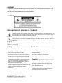
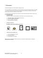
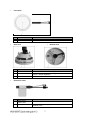
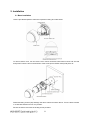
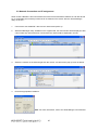
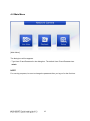
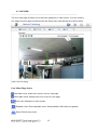
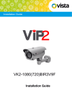
VK2-1080VFD
Installation Guide
2
WARNING
TO REDUCE THE RISK OF FIRE OR ELECTRIC SHOCK, DO NOT EXPOSE THIS PROCUCT TO
RAIN OR MOISTURE. DO NOT INSERT ANY METALLIC OBJECT THROUGH THE VENTILATION
GRILLS OR OTHER OPENNINGS ON THE EQUIPMENT.
CAUTION
EXPLANATION OF GRAPHICAL SYMBOLS
The lightning flash with arrowhead symbol, within an equilateral triangle, is intended to alert the user
to the presence of un-insulated "dangerous voltage" within the product’s enclosure that may be of
sufficient magnitude to constitute a risk of electric shock.
The exclamation point within an equilateral triangle is intended to alert the user to the presence of
important operating and maintenance (servicing) instructions in the literature accompanying the
appliance.
PRECAUTIONS
Safety -------------------------------------- Installation ------------------------------Should any liquid or solid object fall into the cabinet,
unplug the unit and have it checked by the qualified
personnel before operating it any further.
Do not install the unit in an extremely hot or humid
place or in a place subject to excessive dust,
mechanical vibration.
Unplug the unit from the wall outlet if it is not going to
be used for several days or more. To disconnect the
cord, pull it out by the plug. Never pull the cord itself.
The unit is not designed to be waterproof.
Exposure to rain or water may damage the unit.
Allow adequate air circulation to prevent internal heat
build-up. Do not place the unit on surfaces (rugs,
blankets, etc.) or near materials(curtains, draperies)
that may block the ventilation holes.
Cleaning --------------------------------Clean the unit with a slightly damp soft cloth.
Use a mild household detergent. Never use strong
solvents such as thinner or benzene as they might
damage the finish of the unit.
Height and vertical linearity controls located at the rear
panel are for special adjustments by qualified
personnel only.
Retain the original carton and packing materials for
safe transport of this unit in the future.
3
CAUTION:
CHANGES OR MODIFICATIONS NOT EXPRESSLY APPROVED BY THE PARTY
RESPONSIBLE FOR COMPLIANCE COULD VOID THE USER'S AUTHORITY TO OPERATE THE
EQUIPMENT.
CE COMPLIANCE STATEMENT
WARNING: This is a Class A product. In a domestic environment this product may cause radio
interference in which case the user may be required to take adequate measures.
4
Contents
1. Description ................................................................................................. 6
2. Installation .................................................................................................. 8
2.1 Base installation .......................................................................................................8
2.2 Connection ...............................................................................................................9
2.2 Network Connection and IP assignment ................................................................10
3. Operation...................................................................................................11
3.1 Minimum conditions for using web browser ...........................................................11
3.2 Accessing the IP camera ........................................................................................11
4.0 Main Menu ...............................................................................................12
4.1 LIVE VIEW ..............................................................................................................13
4.2 Upgrading the Firmware .........................................................................................14
4.3 General Troubleshooting ........................................................................................15
5
1. Description
This manual applies to the VK2-1080VFD network camera.
The VK2-1080VFD is fully featured for security surveillance and remote monitoring needs. It is based
on the DSP compression chip, and makes it available on the network as real-time, full frame rate
Motion JPEG and H.264 (or MPEG-4) video streams.
The alarm input and alarm output can be used to connect various third party devices, such as, door
sensors and alarm bells.
•
Installation Steps
Follow these steps to install the Network Transmitter on your local network (LAN):
1.
2.
3.
4.
•
Check the package contents against the list below.
Connect the Camera. See page 5.
Set an IP address. See page 7.
Set the password. See page 9.
Package Component
Camera unit
•
Installation CD
Installation Guide
Template Sheet
Accessory Kit
Contents in the installation CD
1. The VK2-1080VFD Full manual
2. VIP2 client software
3. SmartManager set up Utility
Note: Check your package to make sure that you received the complete system, including all
components shown above.
6
•
Front View
NO
1
2
•
Cable
Description
3-9mm varifocal IR corrected lens
IP and Power connection cable
•
Side View
NO
1
•
Name
Lens
Connection
Name
Micro SD Slot
2
Status LED
3
Alarm IO Terminal
Bottom View
Description
Micro SD slot for local recording
Amber : On while System Booting
Green : Normal Operation
AI: Alarm Input, G: Ground, AO: Alarm Output
Extension Cable
NO
Wire Colour
Description
1
Red: DC12V
White: GND
Main Power, 2pin terminal, DC12V 330mA(4.0W)
2
Black
Ethernet, RJ-45 port compatible with 10/100Mbps PoE.
Modular Jack
7
2. Installation
2.1 Base installation
Use the provided template to mark the required mounting and cable holes.
To remove dome cover, turn the dome cover counter clockwise until locators reach end of travel
and pull off. Push the liner in the direction of the arrow (three ‘OPEN’ marks) and pull it off.
Fasten Mounting screws (2X) and align the dome camera as shown above. Turn the dome camera
in a clockwise direction to lock it in position.
Secure the dome cover with the locking screw provided.
8
2.2 Connection
•
Connecting to the RJ-45
Connect a standard RJ-45 cable to the network port of the network camera. Generally a
cross-over cable is used for directly connection to PC, while a direct cable is used for connection
to a switch or hub.
•
Connecting Alarms
AI(Alarm In) :
You can use external devices to signal the VK2-1080VFD to react on events. Mechanical or
electrical switches can be wired to the AI (Alarm In) and G (Ground) connectors in the bottom.
G(Ground) :
Connect the ground side of the alarm input and/or alarm output to the G (Ground) connector.
Alarm Out :
The VK2-1080VFD can activate external devices such as buzzers or lights. Connect the device
to the AO (Alarm Out) and G (Ground) connectors.
•
Connecting Video Output for set up only
Video Output is used for an easy zoom and focus
control when commissioning the camera. Set Video
Switch (SW2 on the board) to On position to output
the video signal. Video Output is restricted to
VGA(640x480) resolution.
Connect your Video cable unit to J5 on the board, as
shown on the adjacent illustration.
Caution: After the camera has been focused, you must set Video Switch SW2 to the OFF
position to provide the best performance of the Network Camera.
•
Connecting the Power (If not using PoE)
Connect the power of 12VDC 330mA for the camera. Connect the positive (+) pole to the ‘+’
position and the negative (-) pole to the ‘-‘position.
9
2.2 Network Connection and IP assignment
When a VK2-1080VFD is first connected to the network it has a default IP address of 192.168.30.220
So, it will probably be necessary to allocate an IP address to the device with the “Smart Manager”
utility on the CD.
1.
Connect the VK2-1080VFD / device to the network and power up.
2.
Start SmartManager utility, available on the supplied CD, the main window will be displayed, after
a short while any network devices connected to the network will be displayed in the list.
3.
Select the camera on the list and right click the mouse. You will see the pop-up menu as below.
4.
Enter the appropriate IP address.
Note: For more information, refer to the Smart Manger User’s Manual.
10
3. Operation
Before powering the camera, installation must be complete. The camera completes a
configuration sequence taking approximately 40 seconds from powering up. Once completed
the LED will be a constant Green.
NOTES
- If the DHCP is enabled but the camera is not connected to a DHCP server, the camera will
be set to a default IP address of192.168.30.220 and will try to obtain an IP address from a
DHCP server every two seconds.
- Network and processor bandwidth limitations might cause the video stream to pause or
appear pixelated when an increased number of Web-interface users connect to the camera.
Decrease the images per second, resolution, compression, or bit rate settings of the Webinterface video streams to compensate for network or processor limitations.
3.1 Minimum conditions for using web browser
The minimum system requirements to use a Web browser with this IP camera are as follows:
- CPU: Pentium® 4 microprocessor, 2.0GHz
- Operational System: Windows XP® or Windows Vista® or Windows7®
- System Memory: RAM 512 Mbyte
- Ethernet: 100 Mbit
- Video Resolution: 1024(Horizontal) x 768(Vertical) pixels or higher
- Internet Explorer® 7 or later
- ActiveX® 1.0.0.13 or later
3.2 Accessing the IP camera
1. Open Web browser
2. Type IP address: - The default IP address is 192.168.30.220
NOTE
- If you do not know the camera’s IP address, install the SmartManager® utility software
available on the CD supplied with the product. The utility software will locate the assigned
Model name, Host name, MAC address, IP address, Version and others.
- Refer to the SmartManager® utility software manual for more detail.
3. Log On to the camera
Default User = admin, default password = admin
- Click the Live View icon for default live image view or the Setup icon to change the
configuration values.
11
4.0 Main Menu
[Main Menu]
The dialog box will be appears.
- Type User ID and Password in the dialog box. The default User ID and Password are
admin.
NOTE
For security purposes, be sure to change the password after you log on for the first time.
12
4.1 LIVE VIEW
-------------------------------------------------------------------------------------------------------------------------
The Live View page provides you to select the properties of video source. You can view the
live image from this page and also access the Setup menu and operate the main functions.
[ Main Live View Page]
Live Video Page Icons
Hide Main Icons: Hides main icons in the live view page.
Show Main Icons: Shows main icons in the live view page.
Live view: Displays live video stream.
Playback View: Enters playback menu. Required Micro SD card (not supplied)
Setup: Enters setup menu.
13
Help: Shows helpful information.
Source: Specify the viewable video stream source to display in live view page.
View Size: Specify the viewable video size to display in live view page.
Stream Type: Specify the internet protocol to display in live view page.
ROI View: Specify the specially selected area to transfer using different stream feature
in the primary video image. ROI is an abbreviation for “Region of Interest”.
Preset: Specify the Preset. This icon is inactivated if the PTZ settings are not set.
Pause: Pause the live video stream.
Snapshot: Take a picture of the video image currently on display. Supports the origin
image size view, Print, and Save feature.
Digital Zoom: Supports a digital zoom in live video image.
Full Screen: Expands video image to the entire screen area.
Manual Trigger: Activates the Alarm Out signalling manually.
Speaker: Adjusts the volume of Speaker and switch the sound on / off.
Microphone: Adjusts the volume of Microphone and switch the sound on / off.
If you suspect a problem is being caused by incorrect configuration or some other minor
problem, consult the troubleshooting guide below.
4.2 Upgrading the Firmware
Firmware is software that determines the functionality of the network camera. One of your
first actions when troubleshooting a problem should be to check the current firmware. The
latest version may contain a correction that fixes your particular problem. The current
14
firmware version in your camera is displayed on the Basic Configuration or About. For the
latest firmware of the camera, please contact with your product administrator.
Detailed instructions on how to perform the upgrade process are provided with each new
release. See also the Maintenance/ Upgrade for more information.
4.3 General Troubleshooting
The following list covers some of the problems that may be encountered and suggests how
to remedy them:
1. The camera cannot be accessed by some clients.
→ If using a proxy server, try disabling the proxy setting in your browser. Check all cabling
and connectors.
2. The camera works locally, but not externally.
→ Check if there are firewall settings that need to be adjusted. Check if there are router
settings that need to be configured.
3. Poor or intermittent network connection.
→ If using a network switch, check that the port on that device uses the same setting for the
network connection type (speed/duplex).
4. The camera cannot be accessed via a host name.
→ Check that the host name and DNS server settings are correct.
5. Not possible to log in.
→ When HTTPS is enabled, ensure that the correct protocol (HTTP or HTTPS) is used.
When attempting to log in, you may need to manually type in http or https in the browser's
address bar.
6. No image using Refresh and/or slow updating of images.
→ If images are very complex, try limiting the number of clients accessing the camera.
7. Images only shown in black & white.
→ Check the Video & Image setting.
8. Blurred images.
→ Refocus the camera.
15
9. Poor image quality.
→ Increased lighting can often improve image quality. Check that there is sufficient lighting at
the monitored location. Check all image and lighting settings.
10. Rolling dark bands or flickering in image.
→ Try adjusting the Exposure Control setting under AE and AWB part.
11. H.264 not displayed in the client.
→ Check that the correct network interface is selected in the Video & Image/Stream.
12. Multicast H.264 not displayed in the client.
→ Check with your network administrator that the multicast addresses used by the camera
are valid for your network. Check that the Enable multicast checkbox are enabled in the
System/Network/RTP tab. Checks with your network administrator to see if there is a firewall
preventing viewing.
13. Multicast H.264 only accessible by local clients.
→ Check if your router supports multicasting, or if the router settings between the client and
the server need to be configured. The TTL value may need to be increased.
14. Colour saturation is different in H.264 and Motion JPEG.
→ Modify the settings for your graphics adapter. Please see the adapter's documentation for
more information.
15. Poor audio quality.
→ Too many users/clients connected to the camera may affect the sound quality adversely.
Try limiting the number of clients allowed to connect.
16. Distorted audio.
→ Check that the correct Audio Input source is selected. Select Microphone for a connected
external microphone. Select Line for a connected line in source.
NOTE
If you cannot find the help you require, please see the User's Manual, or contact with your
network administrator.
16